KR101408557B1 - Venturi drain for self-pumping bearing rolling mills - Google Patents
Venturi drain for self-pumping bearing rolling mills Download PDFInfo
- Publication number
- KR101408557B1 KR101408557B1 KR1020127032082A KR20127032082A KR101408557B1 KR 101408557 B1 KR101408557 B1 KR 101408557B1 KR 1020127032082 A KR1020127032082 A KR 1020127032082A KR 20127032082 A KR20127032082 A KR 20127032082A KR 101408557 B1 KR101408557 B1 KR 101408557B1
- Authority
- KR
- South Korea
- Prior art keywords
- oil
- sleeve
- annular chamber
- discharge
- chamber
- Prior art date
- Legal status (The legal status is an assumption and is not a legal conclusion. Google has not performed a legal analysis and makes no representation as to the accuracy of the status listed.)
- Expired - Fee Related
Links
Images


Classifications
-
- B—PERFORMING OPERATIONS; TRANSPORTING
- B21—MECHANICAL METAL-WORKING WITHOUT ESSENTIALLY REMOVING MATERIAL; PUNCHING METAL
- B21B—ROLLING OF METAL
- B21B31/00—Rolling stand structures; Mounting, adjusting, or interchanging rolls, roll mountings, or stand frames
- B21B31/07—Adaptation of roll neck bearings
- B21B31/074—Oil film bearings, e.g. "Morgoil" bearings
-
- F—MECHANICAL ENGINEERING; LIGHTING; HEATING; WEAPONS; BLASTING
- F16—ENGINEERING ELEMENTS AND UNITS; GENERAL MEASURES FOR PRODUCING AND MAINTAINING EFFECTIVE FUNCTIONING OF MACHINES OR INSTALLATIONS; THERMAL INSULATION IN GENERAL
- F16C—SHAFTS; FLEXIBLE SHAFTS; ELEMENTS OR CRANKSHAFT MECHANISMS; ROTARY BODIES OTHER THAN GEARING ELEMENTS; BEARINGS
- F16C13/00—Rolls, drums, discs, or the like; Bearings or mountings therefor
- F16C13/02—Bearings
-
- F—MECHANICAL ENGINEERING; LIGHTING; HEATING; WEAPONS; BLASTING
- F16—ENGINEERING ELEMENTS AND UNITS; GENERAL MEASURES FOR PRODUCING AND MAINTAINING EFFECTIVE FUNCTIONING OF MACHINES OR INSTALLATIONS; THERMAL INSULATION IN GENERAL
- F16C—SHAFTS; FLEXIBLE SHAFTS; ELEMENTS OR CRANKSHAFT MECHANISMS; ROTARY BODIES OTHER THAN GEARING ELEMENTS; BEARINGS
- F16C33/00—Parts of bearings; Special methods for making bearings or parts thereof
- F16C33/02—Parts of sliding-contact bearings
- F16C33/04—Brasses; Bushes; Linings
- F16C33/06—Sliding surface mainly made of metal
- F16C33/10—Construction relative to lubrication
- F16C33/1025—Construction relative to lubrication with liquid, e.g. oil, as lubricant
- F16C33/1045—Details of supply of the liquid to the bearing
-
- F—MECHANICAL ENGINEERING; LIGHTING; HEATING; WEAPONS; BLASTING
- F16—ENGINEERING ELEMENTS AND UNITS; GENERAL MEASURES FOR PRODUCING AND MAINTAINING EFFECTIVE FUNCTIONING OF MACHINES OR INSTALLATIONS; THERMAL INSULATION IN GENERAL
- F16C—SHAFTS; FLEXIBLE SHAFTS; ELEMENTS OR CRANKSHAFT MECHANISMS; ROTARY BODIES OTHER THAN GEARING ELEMENTS; BEARINGS
- F16C33/00—Parts of bearings; Special methods for making bearings or parts thereof
- F16C33/72—Sealings
- F16C33/74—Sealings of sliding-contact bearings
-
- F—MECHANICAL ENGINEERING; LIGHTING; HEATING; WEAPONS; BLASTING
- F16—ENGINEERING ELEMENTS AND UNITS; GENERAL MEASURES FOR PRODUCING AND MAINTAINING EFFECTIVE FUNCTIONING OF MACHINES OR INSTALLATIONS; THERMAL INSULATION IN GENERAL
- F16C—SHAFTS; FLEXIBLE SHAFTS; ELEMENTS OR CRANKSHAFT MECHANISMS; ROTARY BODIES OTHER THAN GEARING ELEMENTS; BEARINGS
- F16C2320/00—Apparatus used in separating or mixing
- F16C2320/23—Milling apparatus
-
- F—MECHANICAL ENGINEERING; LIGHTING; HEATING; WEAPONS; BLASTING
- F16—ENGINEERING ELEMENTS AND UNITS; GENERAL MEASURES FOR PRODUCING AND MAINTAINING EFFECTIVE FUNCTIONING OF MACHINES OR INSTALLATIONS; THERMAL INSULATION IN GENERAL
- F16C—SHAFTS; FLEXIBLE SHAFTS; ELEMENTS OR CRANKSHAFT MECHANISMS; ROTARY BODIES OTHER THAN GEARING ELEMENTS; BEARINGS
- F16C2322/00—Apparatus used in shaping articles
- F16C2322/12—Rolling apparatus, e.g. rolling stands, rolls
Landscapes
- Engineering & Computer Science (AREA)
- General Engineering & Computer Science (AREA)
- Mechanical Engineering (AREA)
- Chemical & Material Sciences (AREA)
- Oil, Petroleum & Natural Gas (AREA)
- Rolling Contact Bearings (AREA)
- Sliding-Contact Bearings (AREA)
- Centrifugal Separators (AREA)
- Cleaning In General (AREA)
- Magnetic Bearings And Hydrostatic Bearings (AREA)
Abstract
본 발명에 따르면, 회전 슬리브와 슬리브를 둘러싼 고정 부싱 사이로부터 유출되는 오일을 제거하도록 압연 밀 오일 필름 베어링에서 사용되는 시스템이 개시되어 있다. 이 시스템은 오일의 유출 유동을 수용하도록 배열되는 환형 챔버를 포함한다. 챔버는 베어링의 인접한 강성 구성 요소와 접촉되는 가요성 밀봉부에 의해 한정되는 밀봉 계면을 포함하는 구속 표면에 의해 배출 섬프로부터 격리된다. 임펠러가 챔버 내로 돌출되고, 챔버 주위에서 오일을 회전 추진하도록 슬리브와 함께 슬리브의 속도로 회전 가능하다. 방출 도관이 챔버와 접선 방향으로 연통되고, 챔버 주위에서 회전 추진되는 오일의 가압 유동을 수용하도록 배열된다. 벤투리가 방출 도관 내에 위치된다. 흡인 도관이 배출 섬프에 벤투리를 연결한다. 환형 챔버로부터 밀봉 계면을 지나 배출 섬프 내로 탈출되는 오일이 도관을 통한 제거를 위해 벤투리에 의해 흡입된다.According to the present invention, there is disclosed a system for use in a rolling mill oil film bearing to remove oil flowing out between a rotating sleeve and a stationary bushing surrounding the sleeve. The system includes an annular chamber arranged to receive an outflow flow of oil. The chamber is isolated from the discharge sump by a restraining surface that includes a sealing interface defined by a flexible seal contacting the adjacent rigid component of the bearing. An impeller protrudes into the chamber and is rotatable at the speed of the sleeve with the sleeve to propel the oil around the chamber. The discharge conduit is arranged in tangential communication with the chamber and is arranged to receive the pressurized flow of the rotationally propelled oil around the chamber. Venturi is located in the discharge conduit. The aspiration catheter connects the venturi to the discharge sump. Oil escaping from the annular chamber through the sealing interface into the discharge sump is sucked in by the venturi for removal through the conduit.
Description
본 발명은 회전 슬리브(rotating sleeve)와 슬리브를 둘러싼 고정 부싱(stationary bushing) 사이로부터 접선 방향으로 유출되는 오일의 층류(laminar flow)를 제거하도록 압연 밀 오일 필름 베어링(rolling mill oil film bearing)에서 사용되는 시스템에 관한 것이다.The present invention is used in rolling mill oil film bearings to eliminate the laminar flow of oil flowing tangentially between a rotating sleeve and a stationary bushing surrounding the sleeve ≪ / RTI >
전형적인 압연 밀 오일 필름 베어링에서, 슬리브가 롤 네크(roll neck)를 포위하고, 그와 함께 회전 가능하다. 슬리브는 초크(chock) 내에 수용되는 고정 부싱 내에서의 회전을 위해 저널링된다. 슬리브 및 부싱은 그 사이에 간극을 한정하는 치수를 갖는다. 동작 중에, 오일이 간극 내로 계속적으로 유입되고, 여기에서 오일이 베어링의 하중 영역에서 슬리브와 부싱 사이의 유체 역학적으로 유지되는 필름 내로 회전 가능하게 압박된다. 오일의 층류는 베어링의 각각의 단부로부터 섬프(sump) 내로 접선 방향으로 유출되며, 섬프로부터 오일이 베어링으로 재차 재순환되기 전에 여과 및 냉각을 위해 중력에 의해 제거된다.In a typical rolling mill oil film bearing, the sleeve surrounds the roll neck and is rotatable therewith. The sleeve is journaled for rotation in a stationary bushing received in a chock. The sleeve and bushing have dimensions that define a gap therebetween. During operation, oil continues to flow into the gap, where the oil is pivotally pressed into the hydrodynamic retained film between the sleeve and the bushing in the load region of the bearing. The laminar flow of the oil flows out tangentially from each end of the bearing into the sump and is removed by gravity for filtration and cooling before oil is recirculated back to the bearing from the sump.
이러한 배열의 결점에 따르면, 베어링으로부터 유출되는 오일의 중력 유동을 수용하는 데 큰 직경의 배출 라인(drain line)이 요구된다. 이들 배출 라인은 과도한 크기의 외부 공간을 점유하고, 그에 따라 베어링의 전체 크기에 불리하게 기여한다. 오일이 베어링 섬프에 대해 지지되어 범람하는 것을 방지하도록 설계되는 피치로 배출 라인이 적절하게 설치되는 것을 보증하도록 주의가 또한 취해져야 한다.The disadvantage of this arrangement is that a large diameter drain line is required to accommodate the gravity flow of oil flowing out of the bearing. These discharge lines occupy an excessively large external space and thus contribute to the overall size of the bearing. Care must also be taken to ensure that the discharge line is properly installed at a pitch designed to prevent oil from being flooded and supported against the bearing sump.
본 발명에 따르면, 가요성 밀봉부와 인접한 베어링 구성 요소 사이에 수립되는 밀봉 계면을 포함하는 구속 표면이 베어링 섬프로부터 격리되고 슬리브와 부싱 사이로부터 유출되는 오일의 층류를 수용하도록 배열되는 환형 챔버를 한정한다. 이처럼 수용된 오일은 슬리브의 속도 회전되는 임펠러에 의해 챔버 주위에서 회전 추진된다. 방출 도관이 회전 추진되는 오일을 제거하도록 챔버와 접선 방향으로 연통된다. 방출 도관 내의 벤투리가 섬프에 연결된다. 벤투리는 밀봉 계면을 지나 배출 섬프 내로 누출되는 임의의 오일을 흡입하도록 작용한다.According to the present invention, a restraining surface comprising a sealing interface established between a flexible seal and adjacent bearing components is isolated from the bearing sump and defines an annular chamber arranged to receive laminar flow of oil exiting between the sleeve and the bushing do. The oil thus received is propelled by rotation of the sleeve around the chamber by the rotating impeller. The discharge conduit is in tangential communication with the chamber to remove the oil being pumped. Venturi in the discharge conduit is connected to the sump. Venturi acts to draw any oil that leaks into the discharge sump past the sealing interface.
본 발명의 이들 및 다른 특징 및 장점이 이제부터 첨부 도면을 참조하여 더욱 상세하게 설명될 것이다.These and other features and advantages of the present invention will now be described in more detail with reference to the accompanying drawings.
도1은 본 발명에 따른 시스템을 구체화한 압연 밀 오일 필름 베어링을 통한 단면도이다.
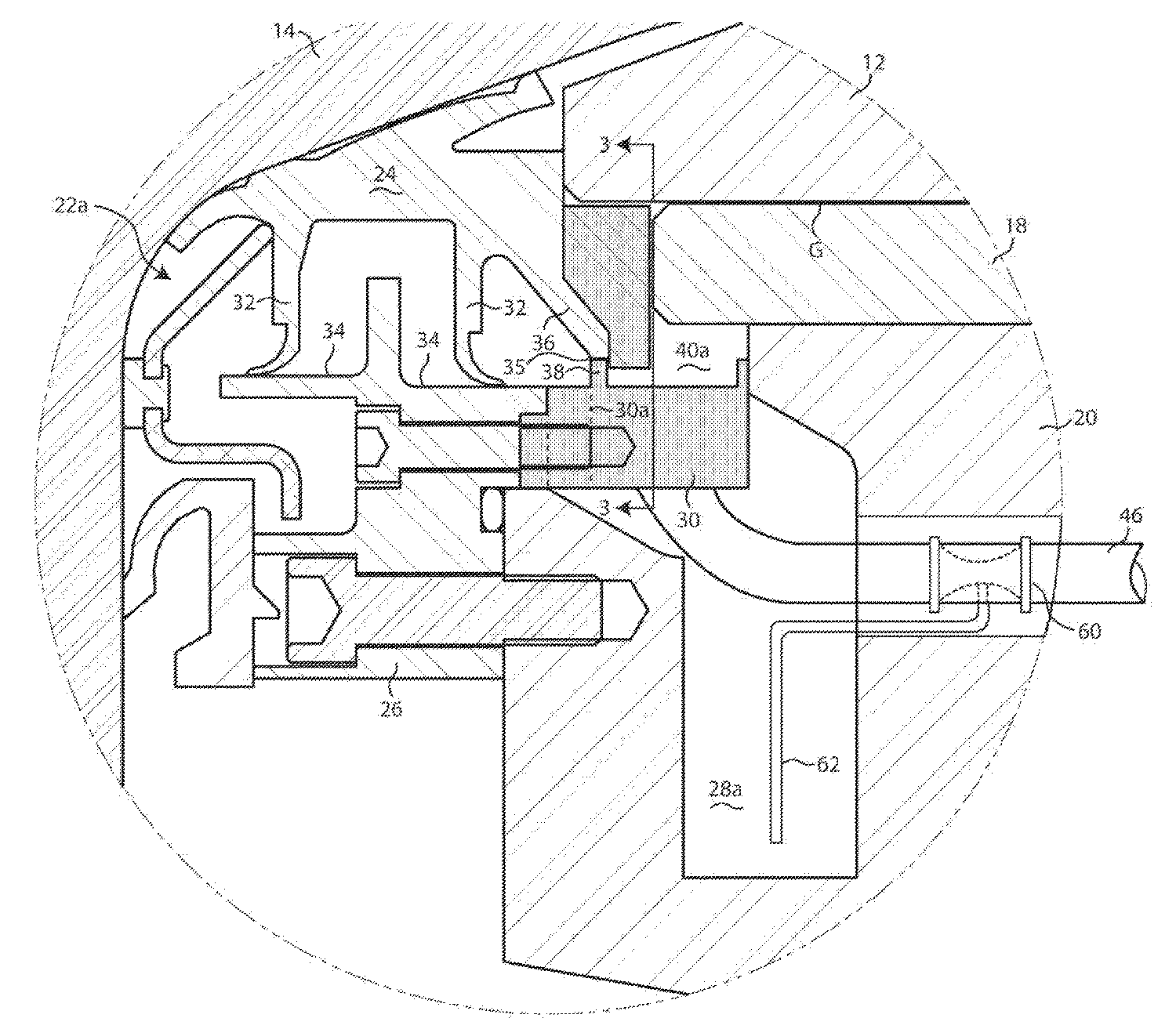
도2는 도1에서 "A"로 표시된 원형 영역의 확대도이다.
도3은 밀봉 단부 판 연장부를 통해 취해진 단면도이다.
도4는 도1에서 "B"로 표시된 원형 영역의 확대도이다.
도5a 및 도5b는 벤투리가 이 시스템 내에 연결될 수 있는 대체예의 방식의 개략도이다.1 is a cross-sectional view through a rolling mill oil film bearing embodying a system according to the present invention;
FIG. 2 is an enlarged view of a circular area indicated by "A" in FIG.
Figure 3 is a cross-sectional view taken through the sealing end plate extension.
4 is an enlarged view of a circular area indicated by "B" in Fig.
5A and 5B are schematic diagrams of alternative ways in which the Venturi can be connected in this system.
우선, 도1을 참조하면, 압연 밀 오일 필름 베어링(10)이 도시되어 있다. 베어링은 롤(16)의 테이퍼형 네크(14)에 고정되는 슬리브(12)를 포함한다. 슬리브는 초크(20) 내에 수용되는 고정 부싱(18) 내에서의 회전을 위해 저널링된다. 슬리브 및 부싱은 그 사이에 간극("G")을 한정하는 치수를 갖는다. 동작 중에, 오일이 간극 내로 계속적으로 유입되고, 여기에서 오일이 베어링의 하중 영역에서 슬리브와 부싱 사이의 유체 역학적으로 유지되는 필름 내로 슬리브에 의해 회전 압박된다. 오일의 층류가 베어링의 양쪽 단부로부터 접선 방향으로 유출된다.Referring first to Figure 1, a rolling mill oil film bearing 10 is shown. The bearing includes a sleeve (12) secured to a tapered neck (14) of the roll (16). The sleeve is journalled for rotation within the
밀봉 조립체(22a, 22b)가 베어링의 내부측 및 외부측 단부에 각각 위치된다. 도2를 추가로 참조하면, 내부측 밀봉 조립체(22a)는 슬리브(12)와 함께 그와의 회전을 위해 테이퍼형 롤 네크 섹션(14) 상에 장착되는 가요성 및 탄성 네크 밀봉부(24)를 포함한다는 것이 관찰될 것이다. 네크 밀봉부는 초크(20)에 고정되는 밀봉 단부 판(26)에 의해 포위된다.The
종래의 베어링에서, 슬리브와 부싱 사이로부터 접선 방향으로 탈출되는 오일의 층류는 섬프(28a) 내에 수용되고, 여기에서 오일이 중력에 의해 배출된다.In a conventional bearing, the laminar flow of oil escaping in a tangential direction between the sleeve and the bushing is received in the
그러나, 본 발명에서, 원형 연장부(30)가 밀봉 단부 판(26)과 초크(20) 사이의 간극에 걸쳐 연장된다. 네크 밀봉부 상의 플랜지(flange)(32)가 밀봉 단부 판 상의 견부(34)와 밀봉 접촉되고, 밀봉 계면(sealing interface)(35)이 연장부(30) 상의 원형 견부(38)와 밀봉 접촉되는 네크 밀봉부 상의 플링거(flinger)(36)에 의해 제공된다. 플링거(36), 연장부(30), 밀봉 계면(35) 및 초크(20)에 의해 제공되는 구속 표면(confinement surface)이 섬프(28a)로부터 격리되고 슬리브와 부싱 사이의 간극(G)으로부터 접선 방향으로 유출되는 오일의 층류를 수용하도록 배열되는 환형 내부측 챔버(40a)를 한정하기 위해 슬리브(12) 및 부싱(18)과 협력한다. 임펠러(42)가 챔버(40a) 내로 돌출된다. 도3을 추가로 참조함으로써 가장 잘 관찰될 수 있는 것과 같이, 임펠러(42)는 네크 밀봉부(24)의 원주부에 의해 보유되고, 그 주위에서 이격된다.However, in the present invention, the
연장부(30)는 밀봉 계면(35)의 내부측 측면 상의 배출 구멍(30a)을 포함한다. 밀봉 계면(35)을 지나 누출되는 임의의 오일이 구멍(30a)을 거쳐 섬프(28a) 내로 배출된다. 도4에 도시된 것과 같이, 연장부(30)는 환형 챔버(40a)와 접선 방향으로 연통되는 출구(44)를 또한 포함한다. 호스(hose)(46)가 출구(44)에 연결되고, (도시되지 않은) 종래의 밀 윤활 시스템으로의 연결을 위해 베어링의 외부로 이어진다.The
출구(44)는 정상 상태 동작 중에 그 챔버가 오일로 충전된 상태로 유지되도록 환형 챔버(40a) 내에 수용되는 오일의 체적과 관련되는 크기를 갖는다. 이전에 언급된 것과 같이, 밀봉부(24) 및 슬리브(12)의 양쪽 모두가 롤 네크(14) 상에 장착되어 그와 함께 회전된다. 이와 같이, 밀봉부(24)에 의해 보유되는 임펠러(42)가 슬리브와 함께 그 속도로 회전된다.The
도4를 참조하면, 유사한 배열이 베어링의 외부측 단부에서 밀봉 조립체(22b)에 의해 제공된다는 것이 관찰될 것이다. 여기에서, 환형 외부측 챔버(40b)가 부싱(18)과 초크(20) 사이에서 연장되는 연장부(48), 슬리브(12)에 고정되는 링(ring)(50), 연장부(48)에 의해 보유되는 립 밀봉부(lip seal)(52) 그리고 립 밀봉부(52)와 링(50) 사이의 밀봉 계면(53) 상의 구속 표면에 의해 한정된다. 임펠러(42)는 슬리브(12)에 고정되고, 슬리브(12)로부터 챔버(40b) 내로 반경 방향으로 돌출된다. 밀봉 계면(53)을 지나 누출되는 임의의 오일이 연장부(48)와 초크(20) 사이의 공간(55)을 거쳐 섬프(28b) 내로 배출된다.Referring to Figure 4, it will be observed that a similar arrangement is provided by the
도시되어 있지 않지만, 연장부(48)가 도4에서의 내부측 출구(44)와 유사한 외부측 출구를 포함한다는 것이 이해되어야 한다. 외부측 출구는 외부측 챔버(40b)와 접선 방향으로 연통되고, 제2 호스(58)에 연결된다.Although not shown, it should be understood that the
도2 및 도5a에 도시된 것과 같이, 벤투리(60)가 방출 도관(46) 내에 배열된다. 흡인 도관(suction conduit)(62)이 섬프(28a)에 벤투리를 연결한다. 도4에 도시된 것과 같이, 방출 도관(58) 내의 제2 벤투리(60')가 흡인 도관(62')에 의해 섬프(28b)에 연결된다.As shown in Figs. 2 and 5A,
대체예에서, 도5b에 도시된 것과 같이, 2개의 섬프(28a, 28b)는 도면 부호 64에서 상호 연결될 수 있고, 2개의 방출 도관(46, 58)은 단일의 도관(66)에 접합될 수 있다. 단일의 벤투리(68)가 도관(66) 내에 위치될 수 있고, 섬프들 중 1개에 단일의 흡인 도관(70)을 거쳐 연결될 수 있다.5b, the two
이와 같이, 임펠러(42)는 환형 챔버(40a, 40b)로부터 오일을 강제로 방출하는 펌핑 작용을 가하도록 선택된 베어링 구성 요소[예컨대, 내부측 단부에서의 네크 밀봉부(24) 그리고 외부측 단부에서의 슬리브(18)]의 회전 운동 에너지를 이용하도록 작용한다는 것이 이해될 것이다. 위에서 언급된 것과 같이, 중력 유동에 의존하기보다는 오일을 강제로 방출함으로써, 더 작은 직경의 방출 도관(46, 48)이 채용될 수 있고, 중력 피치의 유지와 무관하게 전략적으로 위치될 수 있다.As such, the
밀봉 계면(35, 53)을 지나 섬프(28a, 28b) 내로의 오일의 임의의 누출이 방출 도관 내에 전략적으로 위치되는 벤투리에 의해 흡입될 것이고, 그에 의해 모든 오일이 베어링의 정상 상태 동작 중에 효율적으로 재순환되는 것을 보증한다.Any leakage of oil into the
Claims (10)
오일의 유출 유동을 수용하도록 배열되는 환형 챔버로서, 환형 챔버는 베어링의 인접한 강성 구성 요소와 접촉되는 가요성 밀봉부에 의해 한정되는 밀봉 계면을 포함하는 구속 표면에 의해 배출 섬프로부터 격리되는, 환형 챔버와;
환형 챔버 내로 돌출된 임펠러로서, 임펠러는 환형 챔버 주위에서 오일을 회전 추진하도록 슬리브와 함께 슬리브의 속도로 회전 가능한, 임펠러와;
환형 챔버와 접선 방향으로 연통되는 방출 도관으로서, 방출 도관은 환형 챔버 주위에서 회전 추진되는 오일의 가압 유동을 수용하도록 배열되는, 방출 도관과;
방출 도관 내의 벤투리와;
배출 섬프에 벤투리를 연결하는 흡인 도관으로서, 흡인 도관을 통해 환형 챔버로부터 밀봉 계면을 지나 배출 섬프 내로 탈출되는 환형 챔버 내의 오일이 방출 도관을 통한 제거를 위해 흡입되는, 흡인 도관
을 포함하는 시스템.A system for use in a rolling mill oil film bearing to remove oil flowing out between a rotating sleeve and a stationary bushing surrounding the sleeve,
An annular chamber arranged to receive an outflow flow of oil, wherein the annular chamber is separated from the discharge sump by a restraining surface comprising a sealing interface defined by a flexible seal contacting the adjacent rigid component of the bearing, Wow;
An impeller protruding into the annular chamber, the impeller being rotatable at the speed of the sleeve with the sleeve to propel the oil around the annular chamber;
A discharge conduit in tangential communication with the annular chamber, the discharge conduit being arranged to receive a pressurized flow of oil being propelled in rotation about the annular chamber;
Venturi in the discharge conduit;
A suction conduit connecting the venturi to the discharge sump wherein the oil in the annular chamber which escapes from the annular chamber through the suction interface into the discharge sump via the suction conduit is sucked for removal through the discharge conduit,
≪ / RTI >
오일의 유출 유동을 수용하도록 배열되는 환형 챔버로서, 환형 챔버는 밀봉 계면을 포함하는 구속 표면에 의해 배출 섬프로부터 격리되는, 환형 챔버와;
환형 챔버 내로 돌출된 임펠러로서, 임펠러는 환형 챔버 주위에서 오일을 회전 추진하도록 슬리브의 방향으로 그리고 슬리브의 속도로 회전 가능한, 임펠러와;
환형 챔버와 연통되는 방출 도관으로서, 방출 도관은 환형 챔버 주위에서 회전 추진되는 오일의 유동을 수용하도록 배열되는, 방출 도관과;
방출 도관 내의 벤투리와;
배출 섬프에 벤투리를 연결하는 흡인 도관으로서, 흡인 도관을 통해 환형 챔버로부터 밀봉 계면을 지나 배출 섬프 내로 탈출되는 환형 챔버 내의 오일이 방출 도관을 통한 제거를 위해 흡입되는, 흡인 도관
을 포함하는 시스템.A system for use in a rolling mill oil film bearing to remove oil flowing out between a rotating sleeve and a stationary bushing surrounding the sleeve,
An annular chamber arranged to receive an outflow flow of oil, the annular chamber being isolated from the discharge sump by a restraining surface comprising a sealing interface;
An impeller protruding into the annular chamber, the impeller being rotatable in the direction of the sleeve and at the speed of the sleeve to propel the oil around the annular chamber;
A discharge conduit in communication with the annular chamber, the discharge conduit being arranged to receive a flow of rotational propulsion about the annular chamber;
Venturi in the discharge conduit;
A suction conduit connecting the venturi to the discharge sump wherein the oil in the annular chamber which escapes from the annular chamber through the suction interface into the discharge sump via the suction conduit is sucked for removal through the discharge conduit,
≪ / RTI >
상기 슬리브는 롤의 테이퍼형 네크에 고정되고, 밀봉 계면은 롤 네크 상에 장착된 가요성 밀봉부에 의해 한정되고 베어링의 인접한 강성 구성 요소와 접촉하는
시스템.3. The method of claim 2,
The sleeve is fixed to the tapered neck of the roll and the sealing interface is defined by a flexible seal mounted on the roll neck and in contact with adjacent rigid components of the bearing
system.
상기 임펠러는 밀봉부의 원주부에 의해 보유되고 원주부 주위에서 이격되는
시스템. The method of claim 3,
The impeller is held by a circumferential portion of the sealing portion and spaced about the circumferential portion
system.
상기 부싱은 초크 내에 수용되고, 가요성 밀봉부는 초크에 고정되는 밀봉 단부 판에 의해 포위되고, 강성 구성 요소는 밀봉 단부 판의 연장부를 포함하는
시스템.The method of claim 3,
The bushing is received within the choke, the flexible seal is surrounded by a sealing end plate that is secured to the choke, and the rigid component comprises an extension of the sealing end plate
system.
상기 임펠러는 슬리브와 함게 회전하도록 슬리브에 고정되는
시스템.3. The method of claim 2,
The impeller is fixed to the sleeve for rotation with the sleeve
system.
상기 구속 표면은 부싱의 연장부 및 슬리브에 고정된 링에 의해 부분적으로 한정되고, 밀봉 계면은 연장부에 의해 보유되는 립 밀봉부에 의해 한정되고 상기 링과 접촉하는
시스템. The method according to claim 6,
The restraining surface being defined in part by an extension of the bushing and a ring fixed to the sleeve, the sealing interface being defined by a lip seal retained by the extension and being in contact with the ring
system.
상기 방출 도관은 환형 챔버와 접선 방향으로 연통되는
시스템.3. The method of claim 2,
The discharge conduit communicates with the annular chamber in a tangential direction
system.
밀봉 계면을 포함하는 구속 표면에 의해 배출 섬프로부터 격리되는 환형 챔버 내에 오일의 층류를 수용하는 단계와;
회전하는 슬리브의 속도로 환형 챔버 주위에서 오일을 회전 추진하는 단계와;
환형 챔버가 오일로 충전된 상태로 유지되는 속도로 환형 챔버로부터 접선 방향으로 오일을 제거하는 단계와;
동시에, 배출 섬프 내로 밀봉 계면을 지나 탈출되는 임의의 오일을 흡입 및 제거하는 단계
를 포함하는 방법.In a rolling mill oil film bearing, a method for removing laminar flow of oil flowing out in a tangential direction from between a rotating sleeve and a fixed bushing surrounding said sleeve,
Receiving a laminar flow of oil within an annular chamber isolated from the discharge sump by a restraining surface comprising a sealing interface;
Rotating the oil around the annular chamber at a speed of the rotating sleeve;
Removing the oil in a tangential direction from the annular chamber at a rate such that the annular chamber remains filled with oil;
At the same time, the step of sucking and removing any oil escaping past the sealing interface into the discharge sump
≪ / RTI >
각각 상호 연결된 내부측 및 외부측 배출 섬프로부터 격리되고 베어링의 내부측 및 외부측 단부로부터의 오일의 접선 방향으로 유출되는 층류를 수용하도록 배열되는 환형 내부측 및 외부측 챔버를 한정하는 밀봉 계면을 포함하는 구속 표면과;
상기 챔버 내로 돌출된 임펠러로서, 임펠러는 슬리브와 함께 슬리브의 속도로 회전 가능하고 그에 의해 챔버 주위에서 챔버 내에 수용되는 오일을 추진하는, 임펠러와;
상기 챔버와 접선 방향으로 연통되고 임펠러의 회전에 의해 챔버 주위에서 추진되는 오일이 제거되는 공통 방출 도관으로 이어지는 방출 도관과;
공통 방출 출구 내의 벤투리와;
섬프들 중 1개에 벤투리를 연결하는 흡인 도관으로서, 흡인 도관을 통해 밀봉 계면을 지나 배출 섬프 내로 탈출되는 오일이 공통 방출 도관을 통한 제거를 위해 흡입되는, 흡인 도관
을 포함하는 시스템.A system for use in a rolling mill oil film bearing in which oil is introduced between a rotating sleeve and a stationary bushing surrounding the sleeve and the introduced oil flows out in a tangential direction from the inner side and outer side ends of the bearing in laminar flow,
And a sealing interface that defines an annular inner side and an outer side chamber that are arranged to receive laminar flows, each of which is isolated from interconnected inner side and outer side discharge sumps and flows out tangentially to the oil from the inner side and outer side ends of the bearing A restraining surface;
An impeller projecting into the chamber, the impeller being rotatable with the sleeve at the speed of the sleeve, thereby propelling the oil received in the chamber around the chamber;
A discharge conduit communicating in tangential direction with the chamber and leading to a common discharge conduit in which oil propelled around the chamber is removed by rotation of the impeller;
Venturi within the common emission outlet;
A suction conduit connecting the venturi to one of the sumps wherein the oil escaping through the suction conduit into the discharge sump is sucked for removal through the common discharge conduit,
≪ / RTI >
Applications Claiming Priority (3)
| Application Number | Priority Date | Filing Date | Title |
|---|---|---|---|
| US12/796,071 | 2010-06-08 | ||
| US12/796,071 US8342753B2 (en) | 2010-06-08 | 2010-06-08 | Venturi drain for self-pumping bearing rolling mills |
| PCT/US2011/036160 WO2011156079A1 (en) | 2010-06-08 | 2011-05-12 | Venturi drain for self-pumping bearing rolling mills |
Publications (2)
| Publication Number | Publication Date |
|---|---|
| KR20130103339A KR20130103339A (en) | 2013-09-23 |
| KR101408557B1 true KR101408557B1 (en) | 2014-06-17 |
Family
ID=44276274
Family Applications (1)
| Application Number | Title | Priority Date | Filing Date |
|---|---|---|---|
| KR1020127032082A Expired - Fee Related KR101408557B1 (en) | 2010-06-08 | 2011-05-12 | Venturi drain for self-pumping bearing rolling mills |
Country Status (10)
| Country | Link |
|---|---|
| US (1) | US8342753B2 (en) |
| EP (1) | EP2580004B1 (en) |
| JP (1) | JP5683693B2 (en) |
| KR (1) | KR101408557B1 (en) |
| CN (1) | CN102821883B (en) |
| BR (1) | BR112012031332A2 (en) |
| CA (1) | CA2801892C (en) |
| RU (1) | RU2537630C2 (en) |
| TW (1) | TWI471181B (en) |
| WO (1) | WO2011156079A1 (en) |
Families Citing this family (4)
| Publication number | Priority date | Publication date | Assignee | Title |
|---|---|---|---|---|
| US8500332B2 (en) * | 2010-05-05 | 2013-08-06 | Siemens Industry, Inc. | Self pumping oil film bearing |
| DE102012221970A1 (en) | 2012-02-15 | 2013-08-22 | Sms Siemag Ag | Sealing device and roller arrangement |
| CN106151287A (en) * | 2016-07-29 | 2016-11-23 | 如皋市非标轴承有限公司 | A kind of filmatic bearing sealing system based on dummy roll |
| CN112983992A (en) * | 2021-02-07 | 2021-06-18 | 太原重工股份有限公司 | Oil film bearing sealing device and rolling mill oil film bearing |
Citations (4)
| Publication number | Priority date | Publication date | Assignee | Title |
|---|---|---|---|---|
| KR20010006695A (en) * | 1999-02-26 | 2001-01-26 | 게일 엠. 윌콕스 | Seal assembly for rolling mill oil film bearing |
| KR20030035936A (en) * | 2001-10-26 | 2003-05-09 | 스미쓰 앤드 러브리스 인크. | Apparatus and method for extracting particles from a fluid stream |
| KR20030046479A (en) * | 2000-10-02 | 2003-06-12 | 롤스 로이스 아베 | Axially adjustable thrust bearing for jet propulsion units |
| KR20070029598A (en) * | 2005-09-10 | 2007-03-14 | 이에스에이 에핑어 게엠베하 | Lubrication methods and devices for bearing positions in machine tools or parts thereof |
Family Cites Families (25)
| Publication number | Priority date | Publication date | Assignee | Title |
|---|---|---|---|---|
| US2929663A (en) | 1957-05-28 | 1960-03-22 | Gen Motors Corp | Bearing oil scavenger |
| US2848284A (en) | 1957-06-20 | 1958-08-19 | Gen Motors Corp | Bearing oil scavenger |
| US3514167A (en) | 1968-07-03 | 1970-05-26 | Caterpillar Tractor Co | Venturi-type oil seal system for engine crankshafts or the like |
| US3749464A (en) | 1971-09-02 | 1973-07-31 | Johnson Rubber Co | Lubrication system for bearings |
| EP0123991B1 (en) | 1983-04-29 | 1986-11-20 | BBC Brown Boveri AG | Self-priming centrifugal lubrication pump for a turbo charger |
| DE3542316A1 (en) | 1985-09-09 | 1987-03-12 | Kraftwerk Union Ag | DEVICE FOR LEAK OIL-FREE BEARING OIL EXTRACTION ON SLIDING BEARINGS FOR CIRCULAR SHAFTS OF HIGH-TOURED MACHINES |
| US5478090A (en) * | 1993-06-16 | 1995-12-26 | Morgan Construction Company | Interlocked seal and sleeve for rolling mill oil film bearing |
| US5489190A (en) | 1994-07-29 | 1996-02-06 | Alliedsignal Inc. | Dynamic oil scavenge system |
| RU2148737C1 (en) * | 1996-04-26 | 2000-05-10 | Акционерное общество "Электростальский завод тяжелого машиностроения" | Sealing device of liquid friction bearing |
| RU2182269C2 (en) * | 1997-12-26 | 2002-05-10 | Открытое акционерное общество "Электростальский завод тяжелого машиностроения" | Sealing unit of rolling roll bearing assembly |
| US6086255A (en) * | 1998-07-28 | 2000-07-11 | Thompson Industries, Inc. | Hydrostatic bearing and fluid collection system |
| US6851676B2 (en) * | 2002-12-17 | 2005-02-08 | Morgan Construction Company | Inner seal ring for rolling mill oil film bearing |
| US6783131B2 (en) * | 2003-01-31 | 2004-08-31 | Morgan Construction Company | Neck seal |
| US6802511B1 (en) | 2003-02-12 | 2004-10-12 | Morgan Construction Company | Seal end plate |
| DE10316316A1 (en) * | 2003-04-10 | 2004-10-21 | Sms Demag Ag | Device for returning oil in roller bearings |
| US6996968B2 (en) | 2003-12-17 | 2006-02-14 | United Technologies Corporation | Bifurcated oil scavenge system for a gas turbine engine |
| US20050281499A1 (en) * | 2004-06-22 | 2005-12-22 | Wojtkowski Thomas Jr | Oil outlet for rolling mill oil film bearing |
| GB0414619D0 (en) | 2004-06-30 | 2004-08-04 | Rolls Royce Plc | A bearing housing |
| US7334982B2 (en) | 2005-05-06 | 2008-02-26 | General Electric Company | Apparatus for scavenging lubricating oil |
| US7380431B2 (en) * | 2005-07-18 | 2008-06-03 | Morgan Construction Company | Oil film bearing with compact hydraulic mount |
| DE102006016714A1 (en) | 2006-04-08 | 2007-10-11 | Sms Demag Ag | Chock for receiving a roll neck |
| US7857522B2 (en) * | 2007-01-31 | 2010-12-28 | Siemens Industry, Inc. | Rolling mill oil film bearing |
| CN201129455Y (en) * | 2007-12-20 | 2008-10-08 | 宝山钢铁股份有限公司 | A rolling mill oil film bearing sealing device |
| US8500332B2 (en) * | 2010-05-05 | 2013-08-06 | Siemens Industry, Inc. | Self pumping oil film bearing |
| US20110278801A1 (en) * | 2010-05-11 | 2011-11-17 | Morgan Construction Company | Neck seal |
-
2010
- 2010-06-08 US US12/796,071 patent/US8342753B2/en not_active Expired - Fee Related
-
2011
- 2011-05-12 CN CN201180016920.7A patent/CN102821883B/en not_active Expired - Fee Related
- 2011-05-12 JP JP2013514182A patent/JP5683693B2/en not_active Expired - Fee Related
- 2011-05-12 RU RU2012156165/02A patent/RU2537630C2/en not_active IP Right Cessation
- 2011-05-12 CA CA2801892A patent/CA2801892C/en not_active Expired - Fee Related
- 2011-05-12 EP EP11721192.0A patent/EP2580004B1/en active Active
- 2011-05-12 BR BR112012031332A patent/BR112012031332A2/en not_active IP Right Cessation
- 2011-05-12 WO PCT/US2011/036160 patent/WO2011156079A1/en not_active Ceased
- 2011-05-12 KR KR1020127032082A patent/KR101408557B1/en not_active Expired - Fee Related
- 2011-06-01 TW TW100119139A patent/TWI471181B/en not_active IP Right Cessation
Patent Citations (4)
| Publication number | Priority date | Publication date | Assignee | Title |
|---|---|---|---|---|
| KR20010006695A (en) * | 1999-02-26 | 2001-01-26 | 게일 엠. 윌콕스 | Seal assembly for rolling mill oil film bearing |
| KR20030046479A (en) * | 2000-10-02 | 2003-06-12 | 롤스 로이스 아베 | Axially adjustable thrust bearing for jet propulsion units |
| KR20030035936A (en) * | 2001-10-26 | 2003-05-09 | 스미쓰 앤드 러브리스 인크. | Apparatus and method for extracting particles from a fluid stream |
| KR20070029598A (en) * | 2005-09-10 | 2007-03-14 | 이에스에이 에핑어 게엠베하 | Lubrication methods and devices for bearing positions in machine tools or parts thereof |
Also Published As
| Publication number | Publication date |
|---|---|
| CA2801892A1 (en) | 2011-12-15 |
| RU2012156165A (en) | 2014-07-20 |
| RU2537630C2 (en) | 2015-01-10 |
| EP2580004B1 (en) | 2014-12-17 |
| JP2013529547A (en) | 2013-07-22 |
| CN102821883A (en) | 2012-12-12 |
| JP5683693B2 (en) | 2015-03-11 |
| TWI471181B (en) | 2015-02-01 |
| US20110299801A1 (en) | 2011-12-08 |
| US8342753B2 (en) | 2013-01-01 |
| KR20130103339A (en) | 2013-09-23 |
| EP2580004A1 (en) | 2013-04-17 |
| BR112012031332A2 (en) | 2016-10-25 |
| CA2801892C (en) | 2014-09-09 |
| CN102821883B (en) | 2014-12-31 |
| WO2011156079A1 (en) | 2011-12-15 |
| TW201210712A (en) | 2012-03-16 |
Similar Documents
| Publication | Publication Date | Title |
|---|---|---|
| KR101853983B1 (en) | Neck seal for a rolling mill oil film bearing with spaced impellers for propelling oil coming out from the bearing's sleeve and bushing | |
| KR101408557B1 (en) | Venturi drain for self-pumping bearing rolling mills | |
| KR101445015B1 (en) | Self pumping oil film bearing | |
| JP2003529702A (en) | Underwater motor with shaft seal | |
| JP2000509127A (en) | Sealing system for hydraulic machinery | |
| JP2006007324A (en) | Oil outlet for oil film bearing of rolling mill | |
| JP2013529547A5 (en) | System used in rolling mill oil film bearings | |
| JP2017032134A (en) | Bearing device and rotary machine | |
| CN102822529B (en) | Centrifugal Pumps and Seals |
Legal Events
| Date | Code | Title | Description |
|---|---|---|---|
| PA0105 | International application |
St.27 status event code: A-0-1-A10-A15-nap-PA0105 |
|
| PG1501 | Laying open of application |
St.27 status event code: A-1-1-Q10-Q12-nap-PG1501 |
|
| A201 | Request for examination | ||
| A302 | Request for accelerated examination | ||
| P11-X000 | Amendment of application requested |
St.27 status event code: A-2-2-P10-P11-nap-X000 |
|
| P13-X000 | Application amended |
St.27 status event code: A-2-2-P10-P13-nap-X000 |
|
| PA0201 | Request for examination |
St.27 status event code: A-1-2-D10-D11-exm-PA0201 |
|
| PA0302 | Request for accelerated examination |
St.27 status event code: A-1-2-D10-D17-exm-PA0302 St.27 status event code: A-1-2-D10-D16-exm-PA0302 |
|
| E701 | Decision to grant or registration of patent right | ||
| PE0701 | Decision of registration |
St.27 status event code: A-1-2-D10-D22-exm-PE0701 |
|
| GRNT | Written decision to grant | ||
| PR0701 | Registration of establishment |
St.27 status event code: A-2-4-F10-F11-exm-PR0701 |
|
| PR1002 | Payment of registration fee |
St.27 status event code: A-2-2-U10-U12-oth-PR1002 Fee payment year number: 1 |
|
| PG1601 | Publication of registration |
St.27 status event code: A-4-4-Q10-Q13-nap-PG1601 |
|
| PN2301 | Change of applicant |
St.27 status event code: A-5-5-R10-R11-asn-PN2301 |
|
| PN2301 | Change of applicant |
St.27 status event code: A-5-5-R10-R14-asn-PN2301 |
|
| FPAY | Annual fee payment |
Payment date: 20170601 Year of fee payment: 4 |
|
| PR1001 | Payment of annual fee |
St.27 status event code: A-4-4-U10-U11-oth-PR1001 Fee payment year number: 4 |
|
| LAPS | Lapse due to unpaid annual fee | ||
| PC1903 | Unpaid annual fee |
St.27 status event code: A-4-4-U10-U13-oth-PC1903 Not in force date: 20180611 Payment event data comment text: Termination Category : DEFAULT_OF_REGISTRATION_FEE |
|
| PC1903 | Unpaid annual fee |
St.27 status event code: N-4-6-H10-H13-oth-PC1903 Ip right cessation event data comment text: Termination Category : DEFAULT_OF_REGISTRATION_FEE Not in force date: 20180611 |