KR101583473B1 - Glass transfer guide apparatus using magnetic - Google Patents
Glass transfer guide apparatus using magnetic Download PDFInfo
- Publication number
- KR101583473B1 KR101583473B1 KR1020140102314A KR20140102314A KR101583473B1 KR 101583473 B1 KR101583473 B1 KR 101583473B1 KR 1020140102314 A KR1020140102314 A KR 1020140102314A KR 20140102314 A KR20140102314 A KR 20140102314A KR 101583473 B1 KR101583473 B1 KR 101583473B1
- Authority
- KR
- South Korea
- Prior art keywords
- guide
- substrate
- plate
- roller
- magnetic
- Prior art date
- Legal status (The legal status is an assumption and is not a legal conclusion. Google has not performed a legal analysis and makes no representation as to the accuracy of the status listed.)
- Expired - Fee Related
Links
Images


Landscapes
- Rollers For Roller Conveyors For Transfer (AREA)
- Container, Conveyance, Adherence, Positioning, Of Wafer (AREA)
- Framework For Endless Conveyors (AREA)
Abstract
본 발명은 마그네틱을 이용한 기판 이송 안내 장치에 관한것으로, 더욱 상세하게는 이송되는 동일 극성의 마그네틱으로 가이드롤러를 지지하여 기판의 위치가 변경시에 동일극성에 의한 복원력으로 가이드롤러를 회전시켜 기판이 정위치에서 이송될 수 있도록 안내함에 따라 이송 과정 중에 기판 및 가이드롤러의 손상을 방지할 수 있는 마그네틱을 이용한 기판 이송 안내 장치에 관한 것이다. More particularly, the present invention relates to a substrate transfer guide apparatus using magnetic, and more particularly, to an apparatus and a method for supporting a substrate by using a magnet, And more particularly, to a substrate transfer guide apparatus using magnet that can prevent damage to a substrate and a guide roller during a conveying process by guiding the substrate to be conveyed in a predetermined position.
Description
본 발명은 마그네틱을 이용한 기판 이송 안내 장치에 관한것으로, 더욱 상세하게는 이송되는 동일 극성의 마그네틱으로 가이드롤러를 지지하여고, 상기 가이드롤러를 회전가능하도록 고정시켜 기판의 위치가 변경시에 동일극성에 의한 복원력과 가이드롤러의 회전에 의해 기판이 정위치에서 이송될 수 있도록 안내함에 따라 기판 및 가이드롤러의 손상을 방지할 수 있는 마그네틱을 이용한 기판 이송 안내 장치에 관한 것이다. More particularly, the present invention relates to a substrate transfer guide apparatus using magnetic, and more particularly, to a substrate transfer guide apparatus using magnetic, in which a guide roller is supported by a magnet having the same polarity to be transferred, and the guide roller is rotatably fixed, And guide the substrate to be conveyed at a predetermined position by rotation of the guide roller, thereby preventing damage to the substrate and the guide roller.
일반적으로 평판디스플레이는 기판이 이송되면서 여러 공정을 거치는 과정을 통하여 제작된다. 이와 같이 기판이송 안내 장치는 일정한 간격으로 배치되어 구동원에 의하여 회전하는 회전롤러가 구비되고, 상기 회전롤러의 외주에 기판과의 마찰력에 의해 기판을 이송시키는 회전구가 제공된다. In general, a flat panel display is manufactured through a process in which a substrate is transported through various processes. As described above, the substrate transfer guide apparatus is provided with a rotating roller which is arranged at regular intervals and is rotated by a driving source, and a rotary shaft is provided on the outer circumference of the rotating roller for transferring the substrate by frictional force with the substrate.
이때 기판의 양 가장자리에 접촉되는 부분에는 기판의 원활한 이송을 위한 가이드 롤러가 배치된다. 따라서 상기 기판은 상기 가이드 롤러에 의하여 안내되고 회전롤러에 의하여 이송되면서 여러 가지 제조 공정을 거치게 되는 것이다.At this time, a guide roller for smooth conveyance of the substrate is disposed at a portion contacting both edges of the substrate. Accordingly, the substrate is guided by the guide rollers and is transported by the rotating rollers, and is subjected to various manufacturing processes.
이러한 기판 이송 안내 장치는 이미 정해진 규격의 기판이 이송 안내 장치에 의하여 이송되면서 제품을 제조할 수 있는 점에는 별문제가 없으나, 평판디스플레이를 다품종을 생산하는 경우 하나의 이송 라인에서 여러 가지 크기의 기판을 이송할 수 있는 이송 장치가 필요하게 되었다. 특히, 한가지 규격의 기판을 이송할 수 있는 이송 안내 장치가 설치된 경우 크기가 다른 평판디스플레이를 제작할 때 또 다른 이송라인 또는 이송 안내 장치가 필요하여 이송라인 전체를 교체하여야 하기 때문에 고가의 생산설비가 추가로 투입되는 문제점을 갖는다.Although there is no problem in that such a substrate conveying guide apparatus can manufacture a product while a substrate of a predetermined standard is conveyed by a conveying guide apparatus, in case of producing a multi-product of a flat panel display, It is necessary to provide a transferring device capable of transferring the image. In particular, when a conveying guide device capable of transporting one standard substrate is installed, another conveying line or a conveying guide device is required to manufacture a flat panel display of a different size, so that the entire conveying line needs to be replaced. As shown in Fig.
따라서 종래에는 기판을 이송하는 이송 안내 장치에서 여러 가지 크기 폭을 가지는 기판이 이송될 수 있도록 하여 다품종 생산에 적합하여 평판디스플레이의 설비 비용을 줄일 수 있으며, 생산성을 향상시킬 수 있는 기판 이송 안내 장치가 개시되었다. Accordingly, conventionally, a substrate conveying guide device capable of reducing the facility cost of a flat panel display and being able to improve productivity by being suitable for various kinds of production by allowing a substrate having various widths to be transferred in a conveying guide device for conveying a substrate .
종래기술은 베이스에서 기판을 이송시키는 이송수단과, 상기 이송수단에 의하여 상기 기판의 양측 가장자리에 접촉되어 이송되는 상기 기판을 안내하며, 상기 기판의 폭에 따라 거리를 조절할 수 있는 폭 가변 가이드 수단을 포함하는 기판 이송 안내 장치를 제공한다.The conventional technique includes a conveying means for conveying a substrate from a base, a width varying guide means for guiding the substrate conveyed in contact with both side edges of the substrate by the conveying means and adjusting the distance according to the width of the substrate The substrate transfer guide device includes:
이와 같이 이루어지는 종래의 기판 이송 안내 장치는, 비교적 적은 폭을 가지는 기판을 안내하는 경우에는 높이 조절 액츄에이터를 작동시켜 제1 안내롤러를 상측으로 이동시키면 이송되는 기판의 일측면이 상기 제1 안내롤러에 밀착되어 안내가 이루어진다. 그리고 비교적 큰 폭을 가지는 기판을 안내하는 경우에는 높이 조절 액츄에이터를 작동시켜 제2 안내롤러를 하측으로 이동시키면 이송되는 기판의 일측면이 상기 제2 안내롤러에 밀착되어 안내가 이루어진다. 특히, 상기 폭 가변 가이드 수단이 쌍으로 배치되는 경우에는 기판 폭이 더 넓어져도 이송을 위한 안내를 할 수 있게 된다. 또한, 회전 액츄에이터를 회전시키는 것으로 기판 폭의 가장 작은 크기부터 가장 큰 폭을 가지는 사이의 크기를 가지는 기판도 이송을 안내할 수 있게 된다.When a substrate having a relatively small width is to be guided, the conventional substrate transfer guide apparatus having such a structure is configured such that when the height adjusting actuator is operated to move the first guide roller upward, one side of the substrate to be transferred is guided to the first guide roller So that the guide is brought into close contact. In the case of guiding a substrate having a relatively large width, one side of the substrate to be conveyed is brought into close contact with the second guide roller to guide the second guide roller when the height adjusting actuator is operated and the second guide roller is moved downward. In particular, in the case where the width variable guide means are arranged in pairs, it is possible to guide the transfer even if the substrate width is wider. Further, by rotating the rotary actuator, it is possible to guide the transfer of the substrate having the size ranging from the smallest to the largest width of the substrate width.
그러나 상기와 같은 종래 기술은 기판이 직선방향으로 이송되는 것이 아니라 이송과정에서 진동과 같은 현상에 의하여 튀면서 직선방향을 유지하는 것이 아닌 흐트러진 상태로 이송되는 경우가 종종 발생 된다. 이때 종래기술은 기판의 모서리나 양측 단면이 가이드롤러에 접촉되면서 힘을 가하게 됨에 따라 가이드롤러의 표면에 긁힘과 같이 손상이 발생 되어 가이드롤러의 수명이 단축되는 문제점이 있다. However, the above-described conventional technique does not transfer the substrate in a linear direction, but it sometimes occurs that the substrate is transported in a disordered state rather than being maintained in a linear direction while bouncing due to a phenomenon such as vibration during transportation. In this case, according to the prior art, as the edges or both end surfaces of the substrate are pressed against the guide rollers, a force is applied to the surface of the guide rollers, thereby causing damage such as scratches, which shortens the service life of the guide rollers.
또한 종래에는 하나 이상의 기판이 연속으로 이송됨에 따라 이송중인 어느 하나의 기판의 위치가 정위치에서 변형될 경우에 후속되는 기판이나 앞쪽의 기판과의 충돌이 발생되어 기판의 손상이 방지될 수 있는 문제점이 있다. Also, conventionally, as one or more substrates are continuously transferred, when a position of one of the substrates being transferred is deformed at a predetermined position, collision with a subsequent substrate or a front substrate occurs, and damage to the substrate can be prevented .
본 발명은 상기와 같은 종래문제점을 해결하고자 안출된 것으로, 본 발명의 목적은 가이드롤러에 탄성에 의한 충격의 흡수 및 복원력을 부여하여 기판의 이동과정에서 발생되는 충격을 흡수하여 가이드롤러의 손상을 방지할 수 있는 마그네틱을 이용한 기판 이송 안내 장치를 제공함에 있다. SUMMARY OF THE INVENTION The present invention has been made to solve the conventional problems as described above, and it is an object of the present invention to provide an apparatus and a method for absorbing and restoring a shock caused by elasticity of a guide roller, And a substrate transferring device for transferring the substrate.
또한 본 발명의 다른 목적은 하나 이상의 기판이 연속적으로 이동될 시에 어느 하나의 위치가 변형시에 이를 복원하여 연속하여 이송중인 하나 이상의 기판중 어느하나의 흐트러짐에 의한 기판의 충돌로 인한 기판의 손상을 방지할 수 있는 마그네틱을 이용한 기판 이송 안내 장치를 제공함에 있다. It is a further object of the present invention to provide a method and apparatus for repairing a substrate when one or more substrates are continuously moved, And a substrate transfer guide device using the magnet.
본 발명은 상기와 같은 목적을 달성하기 위하여 하기와 같은 실시예를 포함한다. The present invention includes the following embodiments in order to achieve the above object.
본 발명에 따른 마그네틱을 이용한 기판 이송 안내 장치의 바람직한 실시예는 수평 및 수직으로 연장되는 수평 및 수직프레임이 체결되는 지지부재와, 상기 지지부재에 의해 회전가능하도록 고정되어 상면에서 놓여진 기판을 일방향으로 이송시키도록 회전되는 하나 이상의 회전롤러 및 상기 지지부재의 양측면에서 정렬되어 상기 기판의 양측면에 밀착되어 일방향으로 이송되도록 안내하는 하나 이상의 가이드롤러를 구비한 가이드부재를 포함하고, 상기 가이드부재는 상기 지지부재에 고정되는 지지플레이트; 하나 이상으로 분할 형성되고, 각각 좌우방향으로 회전가능하도록 상기 지지부재에 고정되어 상면에 직립된 상기 가이드롤러를 지지하는 가이드플레이트와, 상기 가이드플레이트의 하면에서 연장되어 상기 지지부재에 결합 및 고정되고, 상기 가이드플레이트가 좌우방향으로 회전가능하도록 베어링이 설치되는 결합봉과, 상기 가이드플레이트에서 상호 이격되어 고정되는 한 쌍의 제1자성판과, 상기 지지플레이트에서 상기 제1자성판과 마주보는 위치에서 고정되는 한 쌍의 제2자성판을 포함하고, 상기 가이드롤러는 하나 이상이 그룹화되어 상기 가이드플레이트별로 하나의 그룹이 설치되고, 상기 제1자성판과 제2자성판은 상호 동일극성을 갖고 마주보는 위치에 설치되는 것을 특징으로 한다. A preferred embodiment of the substrate transfer guide device using magnet according to the present invention comprises a support member to which horizontal and vertical frames extending horizontally and vertically are fastened, and a substrate fixed on the upper surface so as to be rotatable by the support member, And a guide member arranged on both sides of the support member and having one or more guide rollers closely attached to both sides of the substrate and guided to be conveyed in one direction, A support plate fixed to the member; A guide plate which is divided into at least one of the guide plates and is supported by the support members so as to be rotatable in the left and right directions and supports the guide rollers upright on the upper surface, A pair of first magnetic plates spaced apart from and fixed to each other in the guide plate, and a pair of second magnetic plates spaced apart from each other at a position facing the first magnetic plate, Wherein the first magnetic plate and the second magnetic plate have the same polarity, and the first magnetic plate and the second magnetic plate have the same polarity, And is installed at a viewing position.
삭제delete
삭제delete
본 발명의 또 다른 실시예에 있어서, 상기 마그네틱판은 상기 가이드플레이트에서 상기 지지플레이트에 마주보는 일측면의 양측 끝단에서 각각 고정되는 한 쌍의 제1자성판; 및 상기 지지플레이트에서 상기 제1자성판과 마주보는 위치에서 고정되는 한 쌍의 제2자성판을 포함하는 것을 특징으로 한다. In another embodiment of the present invention, the magnetic plate may include a pair of first magnetic plates fixed at opposite ends of one side of the guide plate facing the support plate, respectively; And a pair of second magnetic plates fixed to the support plate at positions facing the first magnetic plate.
본 발명의 또 다른 실시예에 있어서, 상기 마그네틱을 이용한 기판 이송 안내 장치는 각각의 명령어가 설정된 다 수개의 키를 구비한 입력부; 상기 입력부에서 구동명령이 인가되면, 상기 회전롤러와 가이드롤러를 구동시키는 제어명령을 출력하는 제어부; 상기 제어부의 제어에 의해 구동되어 상기 가이드롤러를 구동시키는 제1모터와, 상기 회전롤러를 회전시키는 제2모터; 및 상기 제어부의 제어에 의하여 상기 회전롤러 및 가이드롤러의 구동중 상태를 표시하는 표시부를 더 포함한다. In another embodiment of the present invention, the substrate transfer guide apparatus using the magnet includes an input unit having a plurality of keys to which respective commands are set; A control unit for outputting a control command for driving the rotating roller and the guide roller when a driving command is applied to the input unit; A first motor driven by the control unit to drive the guide roller; a second motor for rotating the rotating roller; And a display unit for displaying a driving state of the rotation roller and the guide roller under the control of the control unit.
본 발명은 동일 극성을 갖는 마그네틱에 의한 복원력에 의하여 기판의 이송과정중에 가이드롤러에 가해지는 충격을 흡수할 수 있어 가이드롤러의 수명을 연장시킬 수 있는 효과가 있다. The present invention has the effect of extending the service life of the guide roller by absorbing the shock applied to the guide roller during the conveyance of the substrate by the restoring force by the magnet having the same polarity.
또한 본 발명은 이송되는 기판으로부터 충격이나 힘이 가해지면 회전되면서 충격을 흡수하고, 동일 극성을 갖는 마그네틱에 의한 탄성력으로 원위치로 회전시켜 이송중인 기판을 정 위치로 복원시켜 이송할 수 있어 연속적으로 이송되는 하나 이상의 기판간의 충돌을 방지할 수 있어 이송과정에서 기판의 손상을 방지할 수 있는 효과가 있다. In addition, the present invention absorbs an impact while being rotated when an impact or a force is applied from a substrate to be transferred, and rotates the substrate to an original position by an elastic force of magnet having the same polarity, It is possible to prevent the substrate from being damaged during the transfer process.
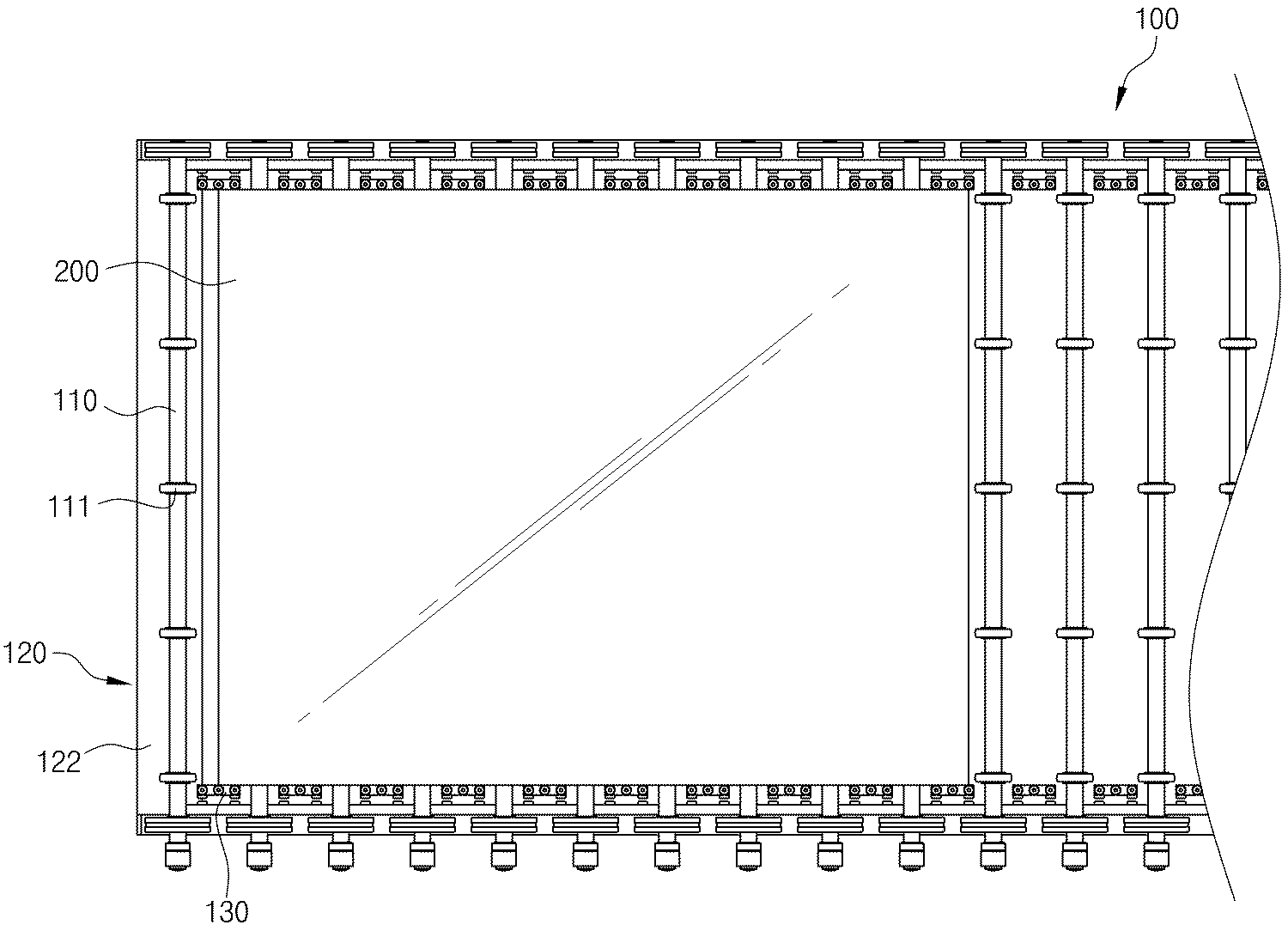
도 1은 본 발명에 따른 마그네틱을 이용한 기판 이송 안내 장치를 도시한 평면도,
도 2는 본 발명에 따른 마그네틱을 이용한 기판 이송 안내 장치를 도시한 정면도,
도 3은 본 발명에 따른 마그네틱을 이용한 기판 이송 안내 장치에서 가이드부재를 확대도시한 사시도,
도 4는 본 발명에 따른 마그네틱을 이용한 기판 이송 안내 장치에서 가이드부재의 평면도,
도 5는 본 발명에 따른 마그네틱을 이용한 기판 이송 안내 장치에서 가이드부재의 측면도,
도 6a 및 도 6b는 본 발명에 따른 마그네틱을 이용한 기판 이송 안내 장치에서 가이드부재의 동작과정을 도시한 평면도,
도 7은 본 발명에 따른 마그네틱을 이용한 기판 이송 안내 장치의 블럭도이다. FIG. 1 is a plan view showing a substrate transfer guide apparatus using magnet according to the present invention, FIG.
FIG. 2 is a front view showing a substrate transfer guide apparatus using magnet according to the present invention. FIG.
FIG. 3 is a perspective view showing an enlarged view of a guide member in the substrate transfer guide apparatus using magnet according to the present invention, FIG.
4 is a plan view of a guide member in the substrate transfer guide apparatus using magnet according to the present invention,
5 is a side view of a guide member in the substrate transfer guide apparatus using magnet according to the present invention,
6A and 6B are a plan view showing the operation process of the guide member in the substrate transfer guide apparatus using magnet according to the present invention,
7 is a block diagram of a substrate transfer guide apparatus using magnet according to the present invention.
이하에서는 본 발명에 따른 마그네틱을 이용한 기판 이송 안내 장치의 바람직한 실시예를 첨부된 도면을 참조하여 상세히 설명한다. DETAILED DESCRIPTION OF THE PREFERRED EMBODIMENTS Hereinafter, preferred embodiments of a substrate transfer guide apparatus using magnet according to the present invention will be described in detail with reference to the accompanying drawings.
도 1은 본 발명에 따른 마그네틱을 이용한 기판 이송 안내 장치를 도시한 평면도, 도 2는 본 발명에 따른 마그네틱을 이용한 기판 이송 안내 장치를 도시한 정면도이다. FIG. 1 is a plan view showing a substrate transfer guide apparatus using magnet according to the present invention, and FIG. 2 is a front view showing a substrate transfer guide apparatus using magnet according to the present invention.
도 1 및 도 2를 참조하면, 본 발명에 따른 마그네틱을 이용한 기판 이송 안내 장치(100)는 수평 및 수직방향으로 연장되는 프레임이 체결되는 지지부재(120)와, 상기 지지부재(120)의 상면에서 다 수개가 회전가능하도록 지지 및 정렬되는 회전롤러(110)과, 상기 회전롤러(110) 사이에서 고정되어 이송되는 극판을 가이드하는 가이드부재(130)를 포함한다. 1 and 2, a substrate
상기 지지부재(120)는 지면에서 직립되는 하나 이상의 수직프레임(121)과, 상기 수직프레임(121) 사이에서 수평으로 연장되는 수평프레임(122)과, 수직프레임(121) 및 수평프레임(122)의 상면에서 직립되어 상기 회전롤러(110) 및 가이드부재(130)를 지지하는 지지프레임(123)을 포함한다. The
상기 수직프레임(121)과 수평프레임(122)은 수평 및 수직방향으로 연결되어 상기 회전롤러(110)과 가이드부재(130)를 지지한다. 여기서 상기 지지프레임(123)은 상기 수직프레임(121) 사이에서 수평으로 연장된 상기 수평프레임(122)의 상면에서 직립되도록 고정되어 일측면에서 상기 회전롤러(110)과 가이드부재(130)가 체결된다. The
상기 회전롤러(110)은 다 수개가 상호 이격 되어 양 끝단이 상기 지지프레임(123)에 각각 회전가능하도록 고정되어 상측의 기판(200)을 이송시키는 회전롤러(110)과, 상기 회전롤러(110)의 외면에서 고정되는 회전구(111)를 포함한다. The rotating
상기 회전롤러(110)은 다 수개가 상호 이격되어 상기 지지부재(120)의 상면에서 회전가능하도록 고정된다. 즉, 상기 회전롤러(110)은 제2모터(145, 도 7 참조)의 구동에 의하여 회전되어 상면에 놓여진 기판(200)을 이동시킨다. 이때 상기 회전구(111)는 상기 회전롤러(110)의 외면에서 하나 이상이 상호 이격된 위치에서 고정되어 상기 회전롤러(110)의 회전시에 기판(200)의 하면과 접촉하여 일방향으로 이동되도록 힘을 전달한다. 여기서 상기 회전구(111)는 상기 기판(200)의 일면과 접촉시에 발생되는 마찰력에 의하여 상기 기판(200)을 이동시킨다. A plurality of the rotating
상기 가이드부재(130)는 상기 회전롤러(110) 사이에 하나 또는 그 이상이 각각 회전가능하도록 고정된다. 이는 첨부된 도 3 내지 도 5를 참조하여 상세히 설명한다. The
도 3은 본 발명에 따른 마그네틱을 이용한 기판 이송 안내 장치에서 가이드부재를 확대도시한 사시도, 도 4는 본 발명에 따른 마그네틱을 이용한 기판 이송 안내 장치에서 가이드부재의 평면도, 도 5는 본 발명에 따른 마그네틱을 이용한 기판 이송 안내 장치에서 가이드부재의 측면도이다. FIG. 3 is a perspective view showing an enlarged view of a guide member in a substrate transfer guide apparatus using magnet according to the present invention, FIG. 4 is a plan view of a guide member in a substrate transfer guide apparatus using magnet according to the present invention, 1 is a side view of a guide member in a substrate transfer guide apparatus using magnet. Fig.
도 3 내지 도 5를 참조하면, 상기 가이드부재(130)는 하나 이상의 가이드롤러(131)와, 상기 가이드롤러(131)를 회전가능하도록 각각 지지하는 하나 이상의 가이드봉(131a)과, 상기 가이드봉(131a)을 직립하도록 지지하는 가이드플레이트(132)와, 상기 가이드플레이트(132)의 하단에서 직립되어 상기 지지부재(120)에 결합되는 결합봉(135)과, 상기 결합봉(135)에 설치되어 상기 가이드플레이트(132) 및 가이드봉(131a)이 좌우로 회전가능하도록 지지하는 베어링(136)과, 상기 지지부재(120)의 측면에 고정되는 지지플레이트(133)와, 상기 지지플레이트(133)와 가이드플레이트(132)에서 상호 대향된 측단면에서 동일 극성을 갖는 마그네틱판(134)을 포함한다. 3 to 5, the
상기 가이드롤러(131)는 하나 이상(131', 131'', 131''', 도 6a, 6b 참조)으로서 상기 가이드봉(131a)의 선단에서 회전가능하도록 고정되어 상기 회전롤러(110)에 의하여 이송되는 기판(200)의 측면을 지지한다. The
상기 가이드봉(131a)은 상기 가이드플레이트(132)의 상면에서 직립되도록 고정되어 선단에 회전가능하도록 고정된 가이드롤러(131)를 지지한다. The
여기서 상기 가이드롤러(131)와 가이드봉(131a)은 상기 가이드플레이트(132)의 상면에서 3개가 한 조로 하여 상기 회전롤러(110) 사이에 각각 설치되는 것으로 도시되었으나, 사업자 또는 설계자의 의도에 의하여 각 회전롤러(110) 사이에 하나의 가이드롤러(131)가 설치되도록 구성함도 가능하다. 이는 설계자의 다양한 응용에 의하여 변형될 수 있다. Here, the
상기 가이드플레이트(132)는 상면에서 상기 가이드봉(131a)을 지지하고, 일측면에서 상기 지지부재(120)와 대향되는 일측면에서 양과 음의 극성중 선택된 어느 하나의 극성을 갖는 마그네틱판(134)이 설치된다. The
상기 결합봉(135)은 상기 가이드플레이트(132)의 하면에서 수직으로 연장되어 상기 지지부재(120)의 수평프레임(122)의 상면에 형성되는 나사공에 체결되도록 끝단에 나사선이 형성되는 결합단(135a)이 형성된다. 즉, 상기 결합봉(135)은 상기 지지부재(120)의 수평프레임(122)에 결합되어 상기 가이드봉(131a) 내지 가이드플레이트(132)를 고정시킨다. The
상기 베어링(136)은 상기 결합봉(135)의 중단에서 설치되어 상기 가이드플레이트(132)가 좌우방향으로 회전가능하도록 지지한다. 이와 같은 베어링(136)에 의한 가이드플레이트(132)의 회전은 도 6을 참조하여 후술한다. The
상기 지지플레이트(133)는 상기 지지부재(120)의 일측면(예를 들면, 상기 수직프레임(121)에서 상기 가이드플레이트(132)의 마그네틱판(134)과 대향되는 일측면)에 상기 가이드플레이트(132)에 설치되는 마그네틱판(134)과 동일 극성을 갖는 마그네틱판(134)이 설치된다. 아울러 상기 지지플레이트(133)는 상기 수직프레임(121)의 일측면에 고정된다. The
상기 마그네틱판(134)은 상기 가이드플레이트(132)와 지지플레이트(133)에서 상호 마주보는 각 측면에서 동일 극성을 갖는 제1자성판(134a, 134a')와 제2자성판(134b, 134b')가 각각 접착된다. The
여기서 상기 제1자성판(134a, 134a')와 제2자성판(134b, 134b')는 각각 상호 이격된 한 쌍으로서 동일극성을 갖는다. 즉, 상기 제1자성판(134a, 134a')는 상기 가이드플레이트(132)의 측면중 일측 끝과 반대쪽 끝에 각각 고정된 한 쌍이며, 상기 제2자성판(134b, 134b')는 상기 지지플레이트(133)의 측면중 일측과 타측 끝에 각각 고정되는 한 쌍으로 설치된다. 또한 상기 제1자성판(134a, 134a')와 제2자성판(134b, 134b')는 상호 마주보는 위치에서 상기 가이드플레이트(132)와 지지플레이트(133)에 각각 고정된다. Here, the first and second
예를 들면, 상기 마그네틱판(134)은 상기 가이드롤러(131)가 상기 베어링(136)에 의하여 일방향으로 회전되면, 해당 위치에서 놓여진 동일 극성의 자성체(134a, 134a', 134b, 134b')가 밀착되면서 서로 밀어내는 힘이 작용된다. 즉, 상기 마그네틱판(134)은 상기 가이드플레이트(132)가 상기 베어링(136)의 회전에 의하여 회전되면, 동일 극성의 자성체간 밀어내는 힘이 작용하여 상기 가이드플레이트(132)를 원위치로 회전시킨다. For example, when the
여기서 상기 가이드롤러(131)와 회전롤러(110)은 도 7에 도시된 바와 같이 각각의 모터(144, 145)에 의하여 구동될 수 있다. 예를 들면, 상기 가이드롤러(131)는 제어부(142)의 제어에 의하여 구동되는 제1모터(144, 도 7참조)에 의해 전달되는 회전력으로 회전되고, 상기 회전롤러(110)은 제어부(142)의 제어에 의하여 구동되는 제2모터(145)에 의하여 전달되는 회전력으로 회전되어 상면으로 이송되는 기판(200)을 일방향으로 이송시킨다. Here, the
상기 제어부(142, 도 7참조)는 각각의 명령어가 설정된 하나 이상의 키(Key)가 설치된 입력부(141)에서 구동명령이 설정된 키가 온되면, 상기 제1모터(144)와 제2모터(145)를 각각 구동시켜 상기 회전롤러(110)과 가이드롤러(131)를 회전시킨다. 7), the
여기서 상기 가이드롤러(131)는 앞서 설명한 도 3 내지 도 5와 같이 상기 기판(200)과의 마찰력에 의해서 회전되도록 구성되는 경우에는 가이드롤러(131)가 상기 가이드봉(131a)의 선단에서 회전되고, 상기 가이드봉(131a)은 상기 가이드플레이트(132)에 직립된 형상으로 고정된다. 3 to 5, when the
또는 상기 가이드롤러(131)는 상기 가이드봉(131a)과 일체로 이루어져 상기 가이드봉(131a)의 회전에 의하여 회전됨도 가능하다. 이와 같은 가이드롤러(131)와 가이드봉(131a)과의 일체형 구조는 상기 제1모터(144)에 의해 상기 가이드롤러(131)를 회전시키기 위해서 설치될 수 있다. 즉, 상기 가이드롤러(131)는 상기 제1모터(144)의 회전축이 연결되는 가이드봉(131a)이 회전됨에 따라서 회전되어 상기 기판(200)의 측면을 안내하여 이송시킨다. 상기와 같은 모터와 가이드롤러(131)간의 연결구성은 동업종의 종사자라면 구현가능한 공지된 기술을 적용함에 따라 구체적인 구성 및 작용설명을 생략하였다. Alternatively, the
또한 본 발명에 따른 마그네틱을 이용한 기판(200)이송 안내 장치(100)는 상기 회전롤러(110) 및/또는 가이드롤러(131)의 구동상태를 작업자가 인지할 수 있도록 구동상태를 발광표시하거나 또는 문자나 기호로서 구동중임을 표시하는 디스플레이중 어느 하나로 이루어진 표시부(143)를 더 포함하는 것도 바람직하다.The substrate conveying and guiding
따라서 작업자가 상기 입력부(141)를 통하여 구동명령을 인가하면, 상기 제1모터(144) 및 제2모터(145)가 구동되어 상기 회전롤러(110)과 가이드롤러(131)가 구동된다. 그러므로 상기 회전롤러(110)의 입력측에서 기판(200)이 이송되면, 상기 회전롤러(110)에 상호 이격된 하나 이상의 회전구(111)와의 마찰력에 의하여 상기 기판(200)이 일방향으로 이송된다. When the operator applies a drive command through the
이때 상기 가이드롤러(131)는 상기 기판(200)의 양측면에서 각각 밀착되면서 상기 기판(200)이 흐트러짐 없이 정방향으로 이송되도록 지지한다. 상술한 바와 같이 상기 가이드롤러(131)는 제1모터(144)에 의해 회전되면서 기판(200)을 안내할 수 있고, 또는 제1모터(144)의 구동이 아닌 기판(200)과의 마찰력에 의해 회전되어 기판(200)을 안내할 수 있다. At this time, the
이때 상기 기판(200)은 상기 회전롤러(110) 및 회전구(111)에 의하여 일방향으로 이송되는 중에 진동이나 기타 원인에 의하여 튕기는 현상으로 인하여 정위치가 아닌 일방향으로 흐트러질 수 있다. 이는 도 6a 및 도 6b를 참조하여 설명한다. At this time, the
도 6a는 본 발명에 따른 마그네틱을 이용한 기판 이송 안내 장치(100)에서 가이드부재(130)가 일방향으로 회전된 예를 도시한 평면도, 도 6b는 일방향으로 회전된 가이드부재(130)가 상기 마그네틱판(134)에 의한 반발력으로 원위치로 복원되는 과정을 도시한 평면도이다. FIG. 6A is a plan view showing an example in which the
도 6a 및 도 6b를 참조하면, 상기 기판(200)은 선단이 정방향을 지향하지 않고, 일측으로 비틀어진 상태가 되는 경우를 가정한다면, 상기 가이드롤러(131)중 일측 끝단에 설치되는 제1가이드롤러(131')의 측면으로 상기 기판(200)이 비틀어짐에 따른 힘이 가해진다. 6A and 6B, it is assumed that the
따라서 상기 가이드플레이트(132)는 상기 제1가이드롤러(131')에서 측방향의 힘이 가해지면 상기 베어링(136)에 의하여 회전된다. 그러므로 상기 제1가이드롤러(131')는 원래의 위치에서 후방으로 회전 되고 제3가이드롤러(131''')가 전방으로 이동된다. 이때 상기 가이드플레이트(132)의 일측 단면에 설치된 제1자성판(134a, 134a') 중 해당 위치에 고정된 제1자성판(134a)과 상기 지지플레이트(133)의 제2자성판(134b)은 상호 동일 극성임에 따라서 반발력이 발생된다. Accordingly, the
즉, 상기 가이드플레이트(132)는 상기 기판(200)에 의해 측방향으로 힘이 가해져 일방향으로 회전되고, 상기 제1자성판(134a)과 제2자성판(134b)이 상호 밀착되면서 동일 극성에 의한 반발력에 의하여 원위치로 회전된다. That is, the
그러므로 상기 기판(200)은 상기 가이드플레이트(132)가 역방향으로 회전되면서 가해지는 힘에 의하여 정방향을 지향하도록 위치가 보정된다. Therefore, the position of the
따라서 본 발명에 따른 마그네틱을 이용한 기판 이송 안내 장치는 연속적으로 이송되는 기판이 이송과정중에 발생되는 흐트러지는 상태가 발생되어 가이드롤러에 걸리게 되더라도 상기 가이드롤러가 회전되면 상기 기판의 충돌에 의한 힘을 흡수함과 동시에 마그네틱판의 동일 극성에 의한 반발력으로 상기 기판을 정위치로 가압하여 복원시킬 수 있다. 그러므로 본 발명은 기판의 이송과정중에 발생되는 가이드롤러 및 기판의 손상을 방지할 수 있고, 가이드롤러의 수명을 연장시킬 수 있다. Therefore, even if the substrate conveyed by the magnetic guide according to the present invention is stuck on the guide roller due to the occurrence of a disordered state in which the continuously transferred substrate is generated during the conveying process, the force due to the collision of the substrate is absorbed And at the same time, the substrate can be pressed and restored by the repulsive force of the same polarity of the magnetic plate. Therefore, it is possible to prevent the guide roller and the substrate from being damaged during transfer of the substrate, and to prolong the service life of the guide roller.
이상에서 본 발명은 기재된 구체 예에 대해서 상세히 설명하였지만 본 발명의 기술사상 범위 내에서 다양한 변형 및 수정 가능함은 당업자에게 있어서 명백한 것이며, 이러한 변형 및 수정이 첨부된 특허청구범위에 속함은 당연한 것이다.While the present invention has been particularly shown and described with reference to exemplary embodiments thereof, it is to be understood that the invention is not limited to the disclosed embodiments, but, on the contrary, is intended to cover various modifications and equivalent arrangements included within the spirit and scope of the appended claims.
100 : 기판이송 안내 장치 110 : 회전롤러
111 : 회전구 120 : 지지부재
121 : 수직프레임 122 : 수평프레임
123 : 지지프레임 130 : 가이드부재
131 : 가이드롤러 131' : 가이드봉
132 : 가이드플레이트 133 : 지지플레이트
134 : 마그네틱판 135 : 결합봉
134a, 134a' : 제1자성판 134b, 135b' : 제2자성판
135 : 결합봉 135a : 결합단
136 : 베어링 200 : 기판100: substrate transfer guide device 110: rotating roller
111: rotation member 120: support member
121: vertical frame 122: horizontal frame
123: support frame 130: guide member
131: guide roller 131 ': guide rod
132: guide plate 133: support plate
134: Magnetic plate 135: Coupling rod
134a, 134a ': first
135:
136: bearing 200: substrate
Claims (5)
상기 지지부재에 의해 회전가능하도록 고정되어 상면에서 놓여진 기판을 일방향으로 이송시키도록 회전되는 하나 이상의 회전롤러; 및
상기 지지부재의 양측면에서 정렬되어 상기 기판의 양측면에 밀착되어 일방향으로 이송되도록 안내하는 하나 이상의 가이드롤러를 구비한 가이드부재;를 포함하고.
상기 가이드부재는
상기 지지부재에 고정되는 지지플레이트;
하나 이상으로 분할 형성되고, 각각 좌우방향으로 회전가능하도록 상기 지지부재에 고정되어 상면에 직립된 상기 가이드롤러를 지지하는 가이드플레이트;
상기 가이드플레이트의 하면에서 연장되어 상기 지지부재에 결합 및 고정되고, 상기 가이드플레이트가 좌우방향으로 회전가능하도록 베어링이 설치되는 결합봉;
상기 가이드플레이트에서 상호 이격되어 고정되는 한 쌍의 제1자성판;
상기 지지플레이트에서 상기 제1자성판과 마주보는 위치에서 고정되는 한 쌍의 제2자성판;을 포함하고,
상기 가이드롤러는 하나 이상이 그룹화되어 상기 가이드플레이트별로 하나의 그룹이 설치되고,
상기 제1자성판과 제2자성판은 상호 동일극성을 갖고 마주보는 위치에 설치되는 것을 특징으로 하는 마그네틱을 이용한 기판 이송 안내장치.
A support member to which horizontal and vertical frames extending horizontally and vertically are fastened;
At least one rotating roller fixed to be rotatable by the supporting member and rotated to convey the substrate placed on the upper surface in one direction; And
And a guide member having one or more guide rollers aligned at both side surfaces of the support member and closely contacting both sides of the substrate and guided to be conveyed in one direction.
The guide member
A support plate fixed to the support member;
A guide plate which is divided into at least one portion and which is fixed to the support member so as to be rotatable in the left and right direction and supports the guide roller erected on the upper surface;
A coupling rod extending from a lower surface of the guide plate and being coupled to and fixed to the support member and having a bearing so that the guide plate is rotatable in the left and right direction;
A pair of first magnetic plates spaced apart from and fixed to each other in the guide plate;
And a pair of second magnetic plates fixed on the support plate at positions facing the first magnetic plate,
One or more guide rollers are grouped so that one group is provided for each of the guide rollers,
Wherein the first magnetic plate and the second magnetic plate are disposed at opposite positions with the same polarity.
각각의 명령어가 설정된 다 수개의 키를 구비한 입력부;
상기 입력부에서 구동명령이 인가되면, 상기 회전롤러와 가이드롤러를 구동시키는 제어명령을 출력하는 제어부;
상기 제어부의 제어에 의해 구동되어 상기 가이드롤러를 구동시키는 제1모터와, 상기 회전롤러를 회전시키는 제2모터; 및
상기 제어부의 제어에 의하여 상기 회전롤러 및 가이드롤러의 구동중 상태를 표시하는 표시부를 더 포함하는 마그네틱을 이용한 기판 이송 안내 장치. 2. The substrate transfer apparatus according to claim 1,
An input unit having a plurality of keys to which respective commands are set;
A control unit for outputting a control command for driving the rotating roller and the guide roller when a driving command is applied to the input unit;
A first motor driven by the control unit to drive the guide roller; a second motor for rotating the rotating roller; And
And a display unit for displaying a driving state of the rotating roller and the guide roller under the control of the control unit.
Priority Applications (1)
| Application Number | Priority Date | Filing Date | Title |
|---|---|---|---|
| KR1020140102314A KR101583473B1 (en) | 2014-08-08 | 2014-08-08 | Glass transfer guide apparatus using magnetic |
Applications Claiming Priority (1)
| Application Number | Priority Date | Filing Date | Title |
|---|---|---|---|
| KR1020140102314A KR101583473B1 (en) | 2014-08-08 | 2014-08-08 | Glass transfer guide apparatus using magnetic |
Publications (1)
| Publication Number | Publication Date |
|---|---|
| KR101583473B1 true KR101583473B1 (en) | 2016-01-11 |
Family
ID=55169803
Family Applications (1)
| Application Number | Title | Priority Date | Filing Date |
|---|---|---|---|
| KR1020140102314A Expired - Fee Related KR101583473B1 (en) | 2014-08-08 | 2014-08-08 | Glass transfer guide apparatus using magnetic |
Country Status (1)
| Country | Link |
|---|---|
| KR (1) | KR101583473B1 (en) |
Cited By (1)
| Publication number | Priority date | Publication date | Assignee | Title |
|---|---|---|---|---|
| CN115744174A (en) * | 2022-10-21 | 2023-03-07 | 彩虹(合肥)液晶玻璃有限公司 | Glass substrate conveying and arranging device |
Citations (5)
| Publication number | Priority date | Publication date | Assignee | Title |
|---|---|---|---|---|
| KR100616291B1 (en) | 2004-06-01 | 2006-08-28 | 주식회사 디엠에스 | Board Transfer Guide Device |
| KR100743466B1 (en) | 2001-06-04 | 2007-07-30 | 주식회사 케이씨텍 | Substrate Sensing Device for Substrate Transport Device |
| KR20080101546A (en) * | 2007-05-18 | 2008-11-21 | (주)리드 | Conveyor device |
| KR20130064338A (en) * | 2011-12-08 | 2013-06-18 | 최제학 | Guide device for substrate transport |
| KR101322716B1 (en) * | 2012-07-04 | 2013-10-28 | 주식회사 선익시스템 | Substrate transferring apparatus using magnetic substance |
-
2014
- 2014-08-08 KR KR1020140102314A patent/KR101583473B1/en not_active Expired - Fee Related
Patent Citations (5)
| Publication number | Priority date | Publication date | Assignee | Title |
|---|---|---|---|---|
| KR100743466B1 (en) | 2001-06-04 | 2007-07-30 | 주식회사 케이씨텍 | Substrate Sensing Device for Substrate Transport Device |
| KR100616291B1 (en) | 2004-06-01 | 2006-08-28 | 주식회사 디엠에스 | Board Transfer Guide Device |
| KR20080101546A (en) * | 2007-05-18 | 2008-11-21 | (주)리드 | Conveyor device |
| KR20130064338A (en) * | 2011-12-08 | 2013-06-18 | 최제학 | Guide device for substrate transport |
| KR101322716B1 (en) * | 2012-07-04 | 2013-10-28 | 주식회사 선익시스템 | Substrate transferring apparatus using magnetic substance |
Cited By (1)
| Publication number | Priority date | Publication date | Assignee | Title |
|---|---|---|---|---|
| CN115744174A (en) * | 2022-10-21 | 2023-03-07 | 彩虹(合肥)液晶玻璃有限公司 | Glass substrate conveying and arranging device |
Similar Documents
| Publication | Publication Date | Title |
|---|---|---|
| KR101067709B1 (en) | Maglev plate feeder | |
| KR102282554B1 (en) | Glass press cutting device, glass press cutting method and glass cutting system | |
| US20170186640A1 (en) | Positioning device for glass substrate | |
| KR101677664B1 (en) | Scribing stage for cutting LCD glass and one-stage LCD glass cutting system having the same | |
| KR101583475B1 (en) | Glass transfer guide apparatus using tension unit | |
| KR20070023958A (en) | Substrate cutting system for liquid crystal display device and Substrate cutting method for liquid crystal display device using the system | |
| CN204384239U (en) | A kind of high-precision flat glass sheet inclination transport sector of lustration type | |
| CN116588689A (en) | A glass group conveying equipment | |
| KR101650683B1 (en) | Clamper for clamping LCD glass and one-stage LCD glass cutting system | |
| KR100978853B1 (en) | Substrate conveying apparatus and its side roller driving method | |
| KR101400156B1 (en) | Plasma Processing Apparatus | |
| KR101328574B1 (en) | Apparatus for transferring substrate | |
| CN103662454B (en) | Substrate box | |
| KR20150090934A (en) | Substrate transfer apparatus | |
| KR20060005844A (en) | Substrate conveying device equipped with a magnet bearing to prevent deflection of the substrate feed shaft | |
| KR20120016835A (en) | Rail-free and contactless transfer system using magnet | |
| KR102223593B1 (en) | Apparatus for controlling slope of stage and apparatus for dividing substrate using the same | |
| KR100898807B1 (en) | Board Transfer Device | |
| CN1847117B (en) | Laminated substrate conveying device | |
| KR101416593B1 (en) | Substrate Transfer Device for Roller Shaft Sagging Prevention | |
| US8967369B2 (en) | Transferring apparatus | |
| KR100903175B1 (en) | Display panel cleaning device with multiple cleaning wheels | |
| KR102400552B1 (en) | Substrate transporting stage, scribing apparatus comprising the same and method for transporting substrate | |
| KR20150073367A (en) | Transport Apparatus | |
| KR102178615B1 (en) | Centering apparatus |
Legal Events
| Date | Code | Title | Description |
|---|---|---|---|
| PA0109 | Patent application |
St.27 status event code: A-0-1-A10-A12-nap-PA0109 |
|
| PA0201 | Request for examination |
St.27 status event code: A-1-2-D10-D11-exm-PA0201 |
|
| D13-X000 | Search requested |
St.27 status event code: A-1-2-D10-D13-srh-X000 |
|
| D14-X000 | Search report completed |
St.27 status event code: A-1-2-D10-D14-srh-X000 |
|
| PE0902 | Notice of grounds for rejection |
St.27 status event code: A-1-2-D10-D21-exm-PE0902 |
|
| E13-X000 | Pre-grant limitation requested |
St.27 status event code: A-2-3-E10-E13-lim-X000 |
|
| P11-X000 | Amendment of application requested |
St.27 status event code: A-2-2-P10-P11-nap-X000 |
|
| P13-X000 | Application amended |
St.27 status event code: A-2-2-P10-P13-nap-X000 |
|
| E701 | Decision to grant or registration of patent right | ||
| PE0701 | Decision of registration |
St.27 status event code: A-1-2-D10-D22-exm-PE0701 |
|
| GRNT | Written decision to grant | ||
| PR0701 | Registration of establishment |
St.27 status event code: A-2-4-F10-F11-exm-PR0701 |
|
| PR1002 | Payment of registration fee |
St.27 status event code: A-2-2-U10-U11-oth-PR1002 Fee payment year number: 1 |
|
| PG1601 | Publication of registration |
St.27 status event code: A-4-4-Q10-Q13-nap-PG1601 |
|
| FPAY | Annual fee payment |
Payment date: 20181213 Year of fee payment: 4 |
|
| PR1001 | Payment of annual fee |
St.27 status event code: A-4-4-U10-U11-oth-PR1001 Fee payment year number: 4 |
|
| PC1903 | Unpaid annual fee |
St.27 status event code: A-4-4-U10-U13-oth-PC1903 Not in force date: 20200105 Payment event data comment text: Termination Category : DEFAULT_OF_REGISTRATION_FEE |
|
| PC1903 | Unpaid annual fee |
St.27 status event code: N-4-6-H10-H13-oth-PC1903 Ip right cessation event data comment text: Termination Category : DEFAULT_OF_REGISTRATION_FEE Not in force date: 20200105 |
|
| R18-X000 | Changes to party contact information recorded |
St.27 status event code: A-5-5-R10-R18-oth-X000 |
|
| R18-X000 | Changes to party contact information recorded |
St.27 status event code: A-5-5-R10-R18-oth-X000 |
|
| R18-X000 | Changes to party contact information recorded |
St.27 status event code: A-5-5-R10-R18-oth-X000 |
|
| P22-X000 | Classification modified |
St.27 status event code: A-4-4-P10-P22-nap-X000 |
|
| R18 | Changes to party contact information recorded |
Free format text: ST27 STATUS EVENT CODE: A-5-5-R10-R18-OTH-X000 (AS PROVIDED BY THE NATIONAL OFFICE) |
|
| R18-X000 | Changes to party contact information recorded |
St.27 status event code: A-5-5-R10-R18-oth-X000 |