KR102012425B1 - Striking unit and method for material processing by the use of high kinetic energy - Google Patents
Striking unit and method for material processing by the use of high kinetic energy Download PDFInfo
- Publication number
- KR102012425B1 KR102012425B1 KR1020167029680A KR20167029680A KR102012425B1 KR 102012425 B1 KR102012425 B1 KR 102012425B1 KR 1020167029680 A KR1020167029680 A KR 1020167029680A KR 20167029680 A KR20167029680 A KR 20167029680A KR 102012425 B1 KR102012425 B1 KR 102012425B1
- Authority
- KR
- South Korea
- Prior art keywords
- plunger
- pressure
- chamber
- valve
- kinetic energy
- Prior art date
- Legal status (The legal status is an assumption and is not a legal conclusion. Google has not performed a legal analysis and makes no representation as to the accuracy of the status listed.)
- Active
Links
Images


Classifications
-
- B—PERFORMING OPERATIONS; TRANSPORTING
- B21—MECHANICAL METAL-WORKING WITHOUT ESSENTIALLY REMOVING MATERIAL; PUNCHING METAL
- B21J—FORGING; HAMMERING; PRESSING METAL; RIVETING; FORGE FURNACES
- B21J7/00—Hammers; Forging machines with hammers or die jaws acting by impact
- B21J7/20—Drives for hammers; Transmission means therefor
- B21J7/46—Control devices specially adapted to forging hammers, not restricted to one of the preceding subgroups
-
- B—PERFORMING OPERATIONS; TRANSPORTING
- B21—MECHANICAL METAL-WORKING WITHOUT ESSENTIALLY REMOVING MATERIAL; PUNCHING METAL
- B21J—FORGING; HAMMERING; PRESSING METAL; RIVETING; FORGE FURNACES
- B21J9/00—Forging presses
- B21J9/10—Drives for forging presses
- B21J9/20—Control devices specially adapted to forging presses not restricted to one of the preceding subgroups
-
- B—PERFORMING OPERATIONS; TRANSPORTING
- B21—MECHANICAL METAL-WORKING WITHOUT ESSENTIALLY REMOVING MATERIAL; PUNCHING METAL
- B21J—FORGING; HAMMERING; PRESSING METAL; RIVETING; FORGE FURNACES
- B21J13/00—Details of machines for forging, pressing, or hammering
- B21J13/02—Dies or mountings therefor
-
- B—PERFORMING OPERATIONS; TRANSPORTING
- B21—MECHANICAL METAL-WORKING WITHOUT ESSENTIALLY REMOVING MATERIAL; PUNCHING METAL
- B21J—FORGING; HAMMERING; PRESSING METAL; RIVETING; FORGE FURNACES
- B21J13/00—Details of machines for forging, pressing, or hammering
- B21J13/06—Hammers tups; Anvils; Anvil blocks
-
- B—PERFORMING OPERATIONS; TRANSPORTING
- B21—MECHANICAL METAL-WORKING WITHOUT ESSENTIALLY REMOVING MATERIAL; PUNCHING METAL
- B21J—FORGING; HAMMERING; PRESSING METAL; RIVETING; FORGE FURNACES
- B21J7/00—Hammers; Forging machines with hammers or die jaws acting by impact
- B21J7/20—Drives for hammers; Transmission means therefor
- B21J7/22—Drives for hammers; Transmission means therefor for power hammers
- B21J7/28—Drives for hammers; Transmission means therefor for power hammers operated by hydraulic or liquid pressure
-
- B—PERFORMING OPERATIONS; TRANSPORTING
- B21—MECHANICAL METAL-WORKING WITHOUT ESSENTIALLY REMOVING MATERIAL; PUNCHING METAL
- B21J—FORGING; HAMMERING; PRESSING METAL; RIVETING; FORGE FURNACES
- B21J9/00—Forging presses
- B21J9/10—Drives for forging presses
- B21J9/12—Drives for forging presses operated by hydraulic or liquid pressure
-
- B—PERFORMING OPERATIONS; TRANSPORTING
- B30—PRESSES
- B30B—PRESSES IN GENERAL
- B30B15/00—Details of, or accessories for, presses; Auxiliary measures in connection with pressing
- B30B15/16—Control arrangements for fluid-driven presses
Landscapes
- Engineering & Computer Science (AREA)
- Mechanical Engineering (AREA)
- Portable Nailing Machines And Staplers (AREA)
- Press Drives And Press Lines (AREA)
- Forging (AREA)
- Presses And Accessory Devices Thereof (AREA)
- Shaping Metal By Deep-Drawing, Or The Like (AREA)
Abstract
본 발명은 높은 운동 에너지의 사용에 의한 재료 프로세싱 시의 방법에 관한 것이며, 단지 한 번의 스트로크에 의해, 프로세싱될 블랭크/공구(4)에 높은 운동 에너지를 전달하기 위해 구동 챔버(11)에 의하여 유압 시스템 압력(pS)에 의해 시작 위치로부터 구동되는 플런저(2)를 포함하며, 그 후에 플런저(2)의 리바운드가 발생할 위험이 있고, 이 방법은 단계가 수행되는 상기 스트로크와 연관되어 취해지는 것을 포함하며, 이 단계는 상기 플런저(2)가 리바운드의 결과로서 부정적인 효과들을 회피하기 위해 운동 에너지의 필수량에 의해 리바운드가 일어나는 것을 방지하고, 그 후에 플런저(2)는 제 2 챔버(10)에 의해 상기 시작 위치로 복귀되고, 상기 단계는 밸브 수단(5)이 시스템 압력(pS)과 플런저(2) 사이의 구동 연결을 닫는 것을 포함하고, 상기 단계는 상기 밸브 수단(5)이 전체 스트라이킹 진행을 제어하는 파일럿 밸브(7)에 의해 제어되는 것을 포함하고, 상기 제 2 챔버(10)는 전체 스트라이킹 진행 동안 시스템 압력(pS)에 의해 가압된다.The present invention relates to a method in the processing of materials by the use of high kinetic energy, which, by only one stroke, is hydraulically driven by the drive chamber 11 to deliver high kinetic energy to the blank / tool 4 to be processed. A plunger 2 driven from the starting position by the system pressure ps, after which there is a risk that rebound of the plunger 2 will occur, the method comprising taking with respect to the stroke in which the step is performed. This step prevents the plunger 2 from being rebounded by the required amount of kinetic energy in order to avoid negative effects as a result of the rebound, after which the plunger 2 is removed by the second chamber 10. Returning to the starting position, the step includes the valve means 5 closing the drive connection between the system pressure pS and the plunger 2, wherein the step The valve means 5 is controlled by a pilot valve 7 which controls the entire strike progress, the second chamber 10 being pressurized by the system pressure pS during the entire strike progress.
Description
본 발명은 높은 운동 에너지(high kinetic energy)의 사용에 의한 재료 프로세싱(processing)을 위한 방법을 위한 스트라이킹 유닛(striking unit)에 관한 것이며, 이는 프로세싱될 블랭크(blank)/공구에 높은 운동 에너지의 전달을 위한 플런저(plunger), 상기 플런저를 구동하도록 설정된(arranged) 시스템(system) 압력에 연결되는 구동 챔버(drive chamber), 상기 구동 챔버로의 유동을 제어하도록 설정되는 밸브(valve) 설비, 및 상기 밸브 설비의 조절을 위한 제어 시스템을 포함하며, 상기 제어 시스템은, 직접적으로 또는 간접적으로, 센서(sensor)에 연결되고, 센서에 의해 상기 밸브 설비는 상기 플런저에 의한 제 1 스트로크(stroke)와 연관되어 제어되어서, 플런저에 대한 힘은 감소되거나 연결 해제되고, 이에 의해 운동 에너지의 필수량(essential content)에 의한 부가적인, 뒤이은 스트로크가 방지되며, 뿐만 아니라, 상기 수행되는 스트로크들과 연관되어 취해지는 단계(이 단계는 리바운드(rebound)에 의한 부정적인 효과들을 회피하기 위해 운동 에너지의 필수량에 의해 플런저가 리바운드되는 것을 방지함)가 취해지는 방법도 방지된다.The present invention relates to a striking unit for a method for material processing by the use of high kinetic energy, which transfers high kinetic energy to a blank / tool to be processed. A plunger for the drive, a drive chamber connected to a system pressure arranged to drive the plunger, a valve arrangement set to control flow to the drive chamber, and the A control system for the adjustment of the valve arrangement, the control system being directly or indirectly connected to a sensor, by which the valve arrangement is associated with a first stroke by the plunger. And controlled so that the force on the plunger is reduced or disconnected, whereby additional, subsequent striation by the essential content of kinetic energy is achieved. Locking is prevented, as well as the step taken in conjunction with the strokes performed (this step prevents the plunger from being rebounded by the required amount of kinetic energy to avoid negative effects by rebound). The way in which is taken is also prevented.
고속 프로세싱에서, 높은 운동 에너지가 재료 본체를 형성 및/또는 프로세스(process)하는데 사용된다. 고속 프로세싱과 연관되어서, 프레스 플런저(press plunger)가 종래의 프로세싱에서보다 본질적으로 더 높은 운동 에너지를 갖는 스트라이킹 기계들이 사용된다. 프레스 플런저는 종종, 크로스 커팅(cross-cutting) 및 펀칭(punching), 금속 성분의 성형, 분말 압착(compacting) 및 유사한 작업들을 수행하기 위해 종래의 프레스들에서보다 약 100배 더 높은 또는 그 초과의 속도를 갖는다. 고속 프로세싱에서, 기술이 제공하는 이점들의 달성을 위해 필요한 높은 운동 에너지들을 달성하기 위한 복수의 상이한 원리들이 있다. 예컨대, WO 9700751 에 도시된 바와 같은, 스트라이킹 본체를 가속하는 수많은 상이한 기계들 및 방법들이 개발되었다. 기계들이 가속을 위해 공기(air), 오일(oil) 스프링(spring)들, 공기-연료-혼합물들, 블라스팅(blasting) 약제(agent)들 또는 전기-기계들(electro-mechanics)을 사용하든 아니든, 모든 이러한 기계들에 대한 공통점은, 원론적으로 어느 하나는, 공구를 향하여 가속되는 스트라이킹 본체를 초래하는 제어되지 않은 프로세스를 발동시키고, 어느 하나는 그 이후 어떠한 방식으로든 특정 시간 후에 스트라이킹 본체를 뒤로 이동시킨다는 점이었다. 또한, 가속력들은 제 1 스트로크 후에 스트라이킹 본체에 계속해서 작용하였고, 이는 몇몇 스트로크들이 제 1 스트로크 후에 발생되는 것을 초래하였다. 이러한 부가적인 스트로크들, 재-스트로크들(re-strokes)은 바람직하지 않고 종종 직접적으로 해가 된다. 또한 성형 공구가 사용되는 경우, 예컨대, 패턴형(patterned) 플레이트(plate)들의 성형에서, 성형 공구가 블랭크와 2회 또는 그 초과로 접촉하게 되지 않는 것이 매우 중요한데, 그러한 경우 플레이트들의 공차가 충족되지 않는 위험이 있기 때문이다.In high speed processing, high kinetic energy is used to form and / or process the material body. In connection with high speed processing, striking machines are used in which a press plunger has an essentially higher kinetic energy than in conventional processing. Press plungers are often about 100 times higher or more than in conventional presses to perform cross-cutting and punching, forming metal components, powder compacting and similar operations. Have speed. In high speed processing, there are a number of different principles for achieving the high kinetic energies required for achieving the advantages provided by the technology. For example, numerous different machines and methods have been developed for accelerating a strike body, as shown in WO 9700751. Whether the machines use air, oil springs, air-fuel-mixtures, blasting agents or electro-mechanics for acceleration Common to all these machines is that, in principle, either triggers an uncontrolled process that results in a strike body accelerating towards the tool, and one moves the strike body back after a certain time in some way thereafter. Was that. In addition, acceleration forces continued to act on the strike body after the first stroke, which resulted in some strokes occurring after the first stroke. Such additional strokes, re-strokes, are undesirable and often directly detrimental. It is also very important when forming tools are used, for example in the formation of patterned plates, that the forming tool does not come into contact with the blank twice or more, in which case the tolerances of the plates are not met. Because there is no risk.
따라서, 대체로 예외들 없이, 작업물(work-piece)이 고속 프로세스에서 한 번의 스트로크 초과를 겪는 것은 단점인 것으로 확인되었다. 이는 크로스-커팅, 균질 성형 또는 분말 압착의 문제이든 아니든 적용된다. 크로스-커팅에서의 문제일 때, 부가적인 불필요한 스트로크들은 과도한 공구 마모 및 바람직하지 않은 버(burr)들을 초래할 수 있다. 펀칭에서, 얼룩(smearing), 용접, 버들 및 공구 마모가 발생할 수 있다. 균질 성형에서, 바람직하지 않은 재료 변경들이 발생할 수 있고, 펀치들이 균열될 수 있고, 블랭크는 매트릭스(matrix)에서 불필요하게 강하게 클램핑될(clamped) 수 있다는 위험이 있고, 이는 그 결과로서 매트릭스 마모와 함께 성형 힘의 증가를 초래한다. 세라믹들, 경질 금속들 등과 같은 취성 재료들과의 분말 압착에서, 제 2 스트로크는, 제 1 스트로크에서 생성하기 위해 다루어진 연속적인 본체를 망가뜨릴 수 있다. 구리 및 철과 같은 연질 분말의 분말 압착에서, 예컨대, 수 회 스트라이크 한다면, 밀도는 실제로 계속해서 증가할 것이지만, 블랭크는 증가된 횟수의 스트로크들에 의해 매트릭스에서 훨씬 더 강하게 클램핑되며, 이는 바람직하지 않은 마모를 초래한다. 이러한 문제에 대하여 이전에 초점이 맞추어지지 않았다는 사실에 대한 있을 수 있는 이유는 이러한 진행이 매우 신속하고 많은 경우들에서 관찰되는 것이 가능하지 않을 수 있으며, 따라서 재-스트로크의 해로운 효과들이 설명 불가능한 것으로 보여왔던 것일 수 있다. 또한, 제 1 스트로크 후에 스트라이킹 본체의 가속을 방해하는 것을 가능하게 하기 위해 요구되는 극도로 짧은 반응 기간들은 그 자체로 문제인 것을 의미한다. 작업자가 어떠한 가스에 의해 스트라이킹 본체를 가속한다면, 원론적으로는, 제 1 스트로크와 제 2 스트로크 사이의 짧은 시간 동안(통상적으로 2 내지 50 밀리초) 구동 챔버의 압력을 감소시키는 것이 기술적으로 불가능하였다. 유압에 의해, 이는 기술적으로 가능하지만, 시장의 대부분의 밸브들은, 종종 20 밀리초 내의 조정이 요구될 수 있는, 짧은 조정 시간들에서 사용될 수 있기에 너무 긴 조정 시간을 갖는다. 스프링 기계들에서와 같이, 수 밀리초 내에서 스프링 바이어스(bias)를 느슨하게 하는 기계적 장치를 형성하는 것이 다소 어렵다는 것도 상당히 명백하다. 상기 명시된 바와 같이, 대부분의 공지된 유압 고속 기계들에는 전진하는 오일을 가로막고 그리하여 플런저의 구동 챔버의 압력의 생성을 막기에 충분히 빠르게 조정될 수 없는 밸브 메커니즘들이 구비된다. 이에 대한 이유는 높은 유동들(300 내지 1000 리터/분(litres/minute))을 위한 유압 밸브들이 보통은 비교적 긴 조정 시간들을 요구한다는 것이다. 이는 차례로 밸브 본체는 상당히 간단하게는 비교적 긴 거리를 이동해야 하며 따라서 충분히 큰 개구 구역이 생성될 것이어서 오일이 너무 큰 압력 강하 없이 이를 통과하는 것이 가능하게 될 것이라는 사실에 달려있다.Thus, generally without exception, it has been found that the work-piece undergoes one stroke overstroke in a high speed process. This applies whether or not it is a matter of cross-cutting, homogeneous molding or powder compaction. When in the cross-cutting problem, additional unnecessary strokes can lead to excessive tool wear and undesirable burrs. In punching, smearing, welding, willow and tool wear may occur. In homogeneous molding, there is a risk that undesirable material changes can occur, punches can crack and the blank can be clamped unnecessarily strongly in the matrix, which, as a result, with matrix wear Results in an increase in molding force. In powder compaction with brittle materials, such as ceramics, hard metals, and the like, the second stroke can break the continuous body treated to produce in the first stroke. In powder compaction of soft powders such as copper and iron, for example, if strike several times, the density will actually continue to increase, but the blank is clamped much more strongly in the matrix by an increased number of strokes, which is undesirable. Cause wear. The possible reason for the fact that this problem has not been previously focused on is that this progress is very rapid and in many cases may not be possible to observe, so the detrimental effects of re-strokes seem to be unexplainable. It may have come. In addition, the extremely short reaction periods required to be able to hinder the acceleration of the striking body after the first stroke mean that it is a problem in itself. If the operator accelerated the strike body by any gas, in principle it was technically impossible to reduce the pressure in the drive chamber for a short time between the first stroke and the second stroke (typically 2 to 50 milliseconds). By hydraulic pressure, this is technically possible, but most valves on the market have an adjustment time that is too long to be used in short adjustment times, which often requires adjustment within 20 milliseconds. As with spring machines, it is also quite obvious that it is rather difficult to form a mechanical device that loosens the spring bias within a few milliseconds. As noted above, most known hydraulic high speed machines are equipped with valve mechanisms that cannot be adjusted quickly enough to intercept the advancing oil and thus prevent the generation of pressure in the drive chamber of the plunger. The reason for this is that hydraulic valves for high flows (300 to 1000 liters / minute) usually require relatively long adjustment times. This in turn depends on the fact that the valve body must travel quite simply a relatively long distance and thus a sufficiently large opening area will be created so that the oil will be able to pass through it without too much pressure drop.
본 발명의 목적은 상기 언급된 문제를 없애거나, 또는 적어도 최소화하는 것이며, 이는 청구항 제 1 항, 제 5 항 및 제 12 항에 따른 방법 및 스트라이킹 유닛(unit)에 의해 달성된다.The object of the present invention is to obviate or at least minimize the above mentioned problems, which are achieved by the method and the striking unit according to
본 발명 덕분에, 고속 프로세싱에서 이전에 공지되었던 것보다 더 높은 품질을 초래하는 방식으로 사용될 수 있는 방법 및 장치가 제공된다.Thanks to the present invention, a method and apparatus are provided that can be used in a manner that results in higher quality than previously known in high speed processing.
본 발명의 양태에 따르면, 유동을 변경하고, 그리하여 가능한 한 빠르게, 플런저를 다음의 스트로크를 위한 그의 시작 위치로 조정할 수 있게 하기 위해, 구동 챔버의 압력을 변경할 수 있는 것은 매우 큰 이점이다. 최적의 해법은 짧은 경로들 및 높은 유동에 의해 얻어진다. 물탱크(cistern) 도관 시스템들 및 물탱크 어큐뮬레이터(accumulator)들의 최적화된 치수는 빠르고 효과적인 압력 감소 그리고 플런저의 복귀를 제공하며, 즉 플런저는 임의의 이중-스트로크/이중 바운드(bound)를 얻지 않으면서 "잡힐 수(caught)" 있다.According to an aspect of the present invention, it is a great advantage to be able to change the pressure of the drive chamber in order to be able to change the flow and thus adjust the plunger to its starting position for the next stroke as soon as possible. The optimal solution is obtained by short paths and high flow. Optimized dimensions of cistern conduit systems and water tank accumulators provide fast and effective pressure reduction and return of the plunger, ie the plunger without obtaining any double-stroke / double bound "Caught".
본 발명의 다른 양태에 따르면, 하나의 온-오프(on-off) 밸브 또는 그 초과가 사용되며, 바람직하게는 스트라이킹 진행을 제어하기 위한 카트리지 밸브(cartridge valve)들을 위한 원리에 따라 기능하며, 이는 다른 대안들과 비교할 때 낮은 비용을 제공한다는 이점 그리고 또한 큰 유동들에서 빠른 조정 시간을 허용한다는 이점을 제공할 수 있다.According to another aspect of the invention, one on-off valve or more is used, preferably functioning according to the principle for cartridge valves for controlling the strike progress, which is Compared to other alternatives it can provide the advantage of providing a low cost and also the advantage of allowing fast adjustment time in large flows.
본 발명의 또 다른 양태에 따르면, 하나의 복귀 밸브 또는 그 초과가 사용되며, 이는 구동 챔버가 더 빠르게 비워지고 다른 밸브들을 완화시키는 이점을 제공한다.According to another aspect of the invention, one return valve or more is used, which provides the advantage that the drive chamber is emptied faster and the other valves are relaxed.
본 발명의 부가적인 양태에 따르면, 적어도 하나의 어큐뮬레이터, 바람직하게는 소위 높은-유동(high-flow) 어큐뮬레이터가 사용되며, 이는 비복귀(nonn-return) 밸브/밸브들에 배열되고, 물탱크에 연결되며 이는 시스템에서 감소된 압력 피크(peak)들 그리고 구동 챔버의 더 빠른 비워냄의 이점을 제공한다.According to an additional aspect of the present invention, at least one accumulator, preferably a so-called high-flow accumulator, is used, which is arranged in a nonn-return valve / valve, and in the water tank This provides the advantage of reduced pressure peaks in the system and faster emptying of the drive chamber.
본 발명의 또 다른 양태에 따르면, 적절하게는 시스템 압력보다 더 높은, 파일럿 압력(pilot pressure)이 파일럿 밸브에 연결되는데, 이는 온-오프/카트리지 밸브의 더 빠른 닫힘을 초래하며, 이는 구동 챔버의 더 빠른 비워냄을 제공하고 또한 온-오프/카트리지 밸브가 스트로크들에서를 제외하고 닫힌 채로 유지되는 것을 의미한다.According to another aspect of the present invention, a pilot pressure, suitably higher than the system pressure, is connected to the pilot valve, which results in a faster closing of the on-off / cartridge valve, which causes It provides faster emptying and also means that the on-off / cartridge valve remains closed except at strokes.
본 발명의 양태에 따르면, 패턴형 플레이트들의 성형과 연관되어 단계가 취해지며, 이 단계는 성형 공구가 성형될 블랭크와 1 회 초과하여 접촉하는 것을 방지한다.According to an aspect of the invention, a step is taken in connection with the shaping of the patterned plates, which step prevents the forming tool from contacting the blank to be molded more than once.
본 발명의 다른 양태에 따르면, 단계는, 스트로크가 일어나지 전에, 양호하게 규정된 홀딩 힘이 성형될 블랭크를 향하여 상부 공구 요소를 프레스하는 단계를 포함하며, 이러한 힘에 의해 상부 공구 요소는 스트로크 후에 상방으로 튀는 것이 가능하지 않게 되며, 이는 블랭크의 해로운 리바운드들을 방지한다.According to another aspect of the invention, the step comprises pressing the upper tool element towards a blank to which a well defined holding force is to be molded, before the stroke takes place, by which the upper tool element is moved upwards after the stroke. It is not possible to bounce off, which prevents harmful rebounds of the blank.
본 발명의 또 다른 양태에 따르면, 단계는 스트로크 후에 상부 공구 요소와 블랭크 사이에 공기가 블로잉되는(blown) 단계를 포함하고, 이 공기는 에어 백(air bag)을 형성하며, 이는 상부 공구 요소가 리바운드시에 블랭크에 도달하지 않는 것을 초래하고 그리하여 블랭크에 대한 손상들을 방지한다.According to another aspect of the invention, the step comprises blowing air between the upper tool element and the blank after the stroke, which air forms an air bag, which This results in not reaching the blank upon rebound and thus avoids damages to the blank.
본 발명의 부가적인 양태에 따르면, 단계는 댐핑(damping)/탄성 요소들이 상부 공구 요소와 연관되어 배열되고 요소들은 상부 공구 요소를 향하여 상방으로, 상부 공구 요소가 리바운드시에 블랭크에 도달하는 것을 방지하기에 충분히 큰 탄성력이 가해지는 단계를 포함한다.According to an additional aspect of the invention, the step is such that the damping / elastic elements are arranged in association with the upper tool element and the elements are upwards towards the upper tool element, preventing the upper tool element from reaching the blank upon rebound. A sufficiently large elastic force is applied below.
이하에서, 본 발명은 첨부된 도면들을 참조하여 더 상세하게 설명될 것이다.
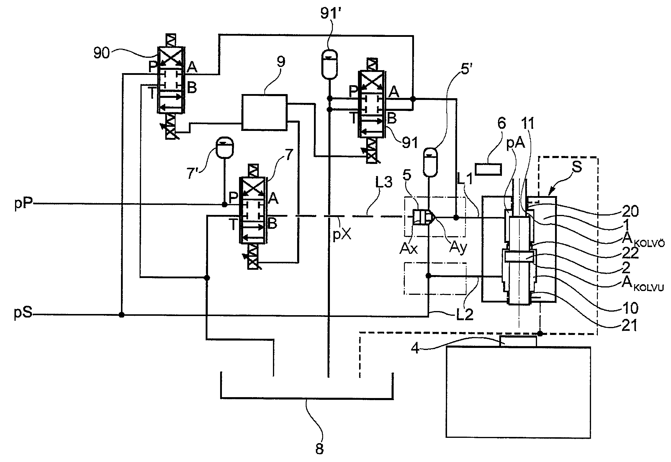
도 1은 본 발명에 따른 스트라이킹 유닛의 원리들을 도시하고;
도 2 내지 도 5는 스트라이킹 유닛의 4 개의 상이한 작업 사이클(cycle)들을 도시하며;
도 6은 본 발명에 따른 공구 해법을 도시하고;
도 7은 본 발명에 따른 대안적인 공구 해법을 도시하며;
도 8은 본 발명에 따른 또 다른 대안적인 공구 해법을 도시하고;
도 9는 스트라이킹 진행의 차트(chart)를 도시하며; 그리고
도 10은 실제 스트로크에 대한 스트라이킹 진행의 차트를 도시한다.In the following, the invention will be explained in more detail with reference to the accompanying drawings.
1 shows the principles of a striking unit according to the invention;
2 to 5 show four different work cycles of the strike unit;
6 shows a tool solution according to the invention;
7 shows an alternative tool solution according to the invention;
8 shows another alternative tool solution according to the invention;
9 shows a chart of strike progress; And
10 shows a chart of strike progress against actual strokes.
도 1은 본 발명의 바람직한 실시예의 스트라이킹 유닛(S)을 위한 기본적인 유압 차트를 도시하고, 여기서 포인트들이 없는 크로싱 도관들은 연통하지 않는다. 도면은, 관통 작업(through work) 플런저(2)를 담고 있는, 원통형 하우징(housing; 1)을 포함하는 스트라이킹 유닛(S)을 도시한다. 바람직하게는, 플런저(2)는 제 1 베어링(bearing; 20) 및 제 2 베어링(21)과 그의 2 개의 단부들이 저널링된다(journalled). 플런저의 중간에 또한 제 3 베어링(22)이 있으며, 이는 2 개의 챔버들, 구동 챔버(11) 및 제 2 챔버(10)가 형성된 것을 의미한다. 플런저(2)는 고속 프로세싱을 위해 블랭크/공구에 높은 운동 에너지를 전달하는 것이 의도된다. 구동 챔버(11)는 밸브 수단(5), 압력 제어된 온/오프 밸브, 바람직하게는 카트리지 밸브에 제 1 도관(L1)을 통하여 연결된다. 카트리지 밸브(5)는 도관(L3)을 통하여 파일럿 압력(pP)에, 밸브를 통하여, 바람직하게는 파일럿 밸브(7)를 통하여 연결된다. 파일럿 밸브 수단이라는 표현은 온-오프/카트리지 밸브(5)를 제어하는 기능성을 충족하는 어떠한 종류의 밸브들을 의미하며, 이는 바람직하게는 다중 경로(multipath) 밸브를 포함하며, 이는 비교적 작은 유압 유동에 의해 더 큰 유동에 대하여 온/오프 밸브를 더 빠르게 조정할 수 있다. 또한, 카트리지 밸브(5)는 도관(L2)을 통하여 시스템 압력(pS)에 연결된다. 카트리지 밸브(5)는 가속시에 구동 챔버(11)의 신속한 압력 증가를 달성하기 위해 압력 어큐뮬레이터(5')에 또한 연결된다. 또한 파일럿 밸브(7)는 압력 어큐뮬레이터(7')에 연결되며, 이는 구동 챔버(11)의 더 빠른 비워냄에 기여한다. 제 2 챔버(10)는 도관(L2)을 통하여 시스템 압력(pS)에 연결된다. 차트는 또한 제어 시스템(9), 센서(6), 서보(servo) 밸브(90) 및 비복귀 밸브(91)를 포함한다. 비복귀 밸브(91)는 압력 감소시에 더 빠른 비워냄에 기여하기 위해 물탱크 어큐뮬레이터(91')에 연결된다.1 shows a basic hydraulic chart for the strike unit S of the preferred embodiment of the present invention, wherein the crossing conduits without points are not in communication. The figure shows a strike unit S comprising a
상기 언급된 3 개의 베어링들(20, 21, 22)은 바람직하게는 서로 상이한 직경들을 가지며, 이는 제 2 챔버(10) 및 구동 챔버(11)의 플런저(2)의 유효 영역들이, 각각, 상이하다는 것을 의미한다. 오일 영향들인, 구동 챔버의 플런저(2)의 유효 영역(


카트리지 밸브(5)를 안전하고 신속하게 작동시키는 것을 가능하게 하기 위해, 파일럿 압력(pP)이 바람직하게 사용되며, 이는 시스템 압력(pS)보다 더 크다.In order to be able to operate the
스트라이킹 유닛(S)의 작업 사이클은, 4 개의 부분들 : 포지셔닝(positioning), 가속, 타격(hit) 및 복귀 동작으로 분할될 수 있다. 상이한 경우들에서 도 2, 도 3 및 도 5의 상이한 도관들에 존재하는 압력들을 기호화하기 위해, 압력들은 이하에 따라 기호화된다 : 


도 2에 포지셔닝 단계가 도시되고, 여기서 제어 시스템(9)은 서보 밸브(90)에 의해 블랭크/공구(4)로부터 미리 선택된 거리에 플런저(2)를 유지한다. 플런저(2)의 현재 위치는 센서(6)에 의해 측정되고, 조정 기능에 의해, 제어 시스템(9)은 도관(L1)의 압력(


도 3에 가속 단계가 도시되고, 여기서 조정 기능은 비활성화되며, 서보 밸브(90)는 파일럿 밸브(7)가 (다소) 포지티브하게(positively)(B

이며, 이는 플런저(2)가 하방으로 빠르게, 종종 10 m/s 를 넉넉하게 초과하는, 또한 종종 12 m/s 초과하는 결과적인 속도로 가속되는 것을 의미한다. 카트리지 밸브(5)는 따라서 시스템 압력(pS)을 제 1 도관(L1)과 연결시켜서, 구동 챔버(11)는 가압되고, 그 후 L1 및 L2 를 통하여, 챔버들 사이에서 유동 경로를 또한 연결하여서, 하부 챔버(10)로부터 변위된 오일은 구동 챔버(11)로 유동할 수 있다. 카트리지 밸브(5)가 압력 어큐뮬레이터(5')에 연결된다는 사실 덕분에, 구동 챔버(11)의 신속한 압력 증가가 도달된다. 비복귀 밸브(91)는 가속 동안 닫히고 중심 위치에 놓인다.This means that the
도 4는 타격 단계를 도시한다. 플런저(2)는 프로세싱될 블랭크/공구(4)를 타격하고 그 자체의 탄력 및 블랭크/공구의 탄력을 통하여 특정한 복귀 동작/바운드를 얻는다. 플런저(2)가 블랭크/공구(4)를 타격할 때까지 대략 일정한 가속을 갖기 때문에, 타격 속도는 가속 페이즈(phase) 전의 포지셔닝에서 블랭크/공구(4)까지의 거리에 달려있다.4 shows the striking step. The
도 5는 복귀 동작 단계를 도시한다. 타격 후에, 구동 챔버(11)의 압력(pA)은 빠르게 감소되어야만 하며, 따라서 플런저(2)는 다시 하방으로 강제되지 않고 제 2 타격을 할 위험이 없어진다. 파일럿 밸브(7)는 네거티브 개방 위치에 놓여서, 카트리지 밸브 콘의 작동 영역(Ax)은 압력(pP)을 얻고 닫힌 위치를 향하여 이동한다. 비복귀 밸브(91)는 최대한 포지티브 위치로 놓여서 구동 챔버(11)는 물탱크(8)에 연결되고, 제 2 챔버(10)의 시스템 압력(pS)은 플런저(2)를 블랭크/공구(4)로부터 멀리 구동시킨다. (이러한 경우 대신 최대한 네거티브 위치로 개방될 수 있으며, 이는 개구(P 및T)들이 연결되고 개구(A 및 B)들이 연결되기 때문에, 동일한 기능을 제공한다.) 조정 기능이 활성화되는데, 이는 서보 밸브가 구동 챔버(11)의 압력을 감소시키기 위해 그리고 포지셔닝 단계에 따라 결정된 시작 위치로 플런저(2)를 제어하기 위해 네거티브하게 개방(A
다음 스트로크를 위한 시작 위치로 플런저(2)를 조정하는 것이 가능하도록 구동 챔버(11)를 가능한 한 빠르게 비워내는 것이 매우 유리하다. 상기 설명된 디자인(design) 덕분에, 짧은 경로들 및 높은 유동, 물탱크 도관 시스템 및 물탱크 어큐뮬레이터들의 최적의 치수를 갖춘 해법이 얻어지고, 이는 빠르고 효과적인 압력 감소 및 플런저(2)의 복귀를 초래하고, 즉 플런저(2)는 이중 스트로크들/이중 바운드들을 얻지 않으면서 "잡힐 수" 있다. 큰/빠른 유동들, 바람직하게는 최소(min.) 900 l/min, 더 바람직하게는 최소 1,000 l/m 를 다루는 것을 가능하게 하기 위해, "높은 유동" 타입(보통은 디스크(disk) 밸브가 구비됨)의 물탱크 어큐뮬레이터가 바람직하다. 적절하게는 어큐뮬레이터(또는 그 초과)는 어큐뮬레이터가/어큐뮬레이터들이 바닥부에 도달하는 위험이 회피되도록 적응되며, 즉 치수는 특정한 보조 체적(volume)이 최대 요구에서 또한 남아있어야 한다.It is very advantageous to empty the
스트로크 전의 플런저 위치의 조정은 상기 설명에 따른 서보 기능에 의해 수행된다. 제어 시스템(9)은 서보 밸브(90) 및 파일럿 밸브(7)의 동역학적 제어를 제공하고, 이는 스트라이킹 유닛의 모델, 시간-거리 함수, 선택된 스트로크 길이 등에 기초하여 시간 제어를 동역학적으로 계산함으로써 스트로크를 위한 카트리지 밸브(5)에 영향을 미친다. 계산으로부터의 출력은 플런저(2)가 충돌 헤드(impact head; 41)에 도달하는데 얼마나 오랜 시간이 걸리는가에 대한 시간을 제공하고, 그 후에, 이는 밸브들을 닫기 위한 입력으로서 사용된다. 조정 알고리즘(algorithm)을 위한 파라미터(parameter)들의 선택은 각각의 스트라이킹 유닛(S)에 대하여 적응된다. 바람직하게는, 조정 알고리즘은 시작 파라미터들의 계산 후에 적응적일 수 있다. 이는 극도로 빠른 진행들의 문제이며, 이는 수십 밀리초 분의 일의 제어 정확도를 제공한다.The adjustment of the plunger position before the stroke is performed by the servo function according to the above description. The
따라서, 압력 어큐뮬레이터들의 기능은 무엇보다도 빠른 진행 동안 충분한 오일이 있는 것을 보장하는 것이다. 압력 어큐뮬레이터들이 없다면 훨씬 더 큰 펌프가 짧은 시간 동안 발생하는 큰 유동들을 충족시키는 것을 가능하게 하기 위해 요구되었을 것이다. 물탱크 어큐뮬레이터들은, 구동 챔버가 비워질 때, 물탱크 어큐뮬레이터가 일시적으로 오일로 채워지는 것을 가능하게 함으로써 시스템을 완화시킨다. 압력이 감소되기 전에 또한 훨씬 더 긴 시간이 걸릴 수 있는데, 오일이 그 후 물탱크 도관들을 통하여 물탱크(8)가 비워져야만 하기 때문이며, 이는 긴 경로를 제외하고, 호스들에 특정 저항이 있다는 단점을 갖는다.Thus, the function of the pressure accumulators is to ensure that there is sufficient oil, among other things, for a fast run. Without pressure accumulators a much larger pump would have been required to make it possible to meet the large flows occurring in a short time. The water tank accumulators relax the system by enabling the water tank accumulator to be temporarily filled with oil when the drive chamber is empty. It may also take a much longer time before the pressure is reduced, since the oil must then be emptied of the
도 9는 상이한 작업 사이클들이 스트라이킹 진행에서 일어날 때를 나타내는 차트를 도시한다. 시간은 차트의 X 축에 ms 로 도시되고, 스트라이킹 본체의 위치는 차트의 Y 축에 mm 로 도시된다. 연속 라인은 본 발명에 따라 수행되는 스트로크를 도시하는 반면, 파선은 종래의 스트로크가 어떻게 일어나는지를 도시한다. 시간의 제 1 경과 동안 2 개의 곡선들이 서로 동행하는 것을 볼 수 있으며, 즉 정확하게 동일한 가속 및 동작이 시작 위치(T0)로부터 스트로크의 달성까지 뿐만 아니라 복귀 동작의 부분 동안에 달성된다. 종래의 방법에 따르면, 그 후에 복수의 재-스트로크들이 발생하고, 이는 바람직하지 않은 결과들을 초래할 수 있다. 본 발명에 따르면, 유동이 구동 챔버(11)에서 신속하게 변경되고 빠른 비워냄이 수행될 수 있기 때문에 이러한 것이 회피된다. 상기 설명에 따르면, T0 에서 가속이 따라서 시작하고, T1 에서 타격이 발생하고, T2 에서 플런저(2)가 잡히고 복귀 동작이 일어나고, T3 에서 플런저(2)의 새로운 포지셔닝이 발생한다.9 shows a chart showing when different work cycles occur in the strike progress. The time is shown in ms on the X axis of the chart and the position of the strike body is shown in mm on the Y axis of the chart. Continuous lines illustrate the strokes performed in accordance with the present invention, while dashed lines illustrate how conventional strokes occur. It can be seen that the two curves coincide with each other during the first elapse of time, ie exactly the same acceleration and motion is achieved during the part of the return motion as well as from the start position T 0 to the achievement of the stroke. According to the conventional method, a plurality of re-strokes then occur, which can lead to undesirable results. According to the invention, this is avoided because the flow is changed quickly in the
도 10은, 플런저(2)가 250 ㎏ 의 질량을 갖고 앤빌(anvil) 및 공구의 질량이 12 톤(ton)일 때, 실제 스트로크의 차트를 도시한다. 차트의 X 축에는 시간이 ms 로 도시되고 차트의 Y 축에는 플런저의 위치가 mm 로 도시된다. 시작 위치는 T0 으로 표시되는데, 즉 여기서 가속이 시작되고, T1 에서 타격이 발생하며, T2 에서 플런저(2)가 잡히고, T3 에서 플런저(2)의 새로운 포지셔닝이 일어나는데, 즉, 플런저(2)의 시작(T0)으로부터 캡쳐(capture)(T2)까지 35 ms 의 시간이 걸린다.FIG. 10 shows a chart of the actual stroke when the
기계 크기와 스트라이킹 파라미터들에 따라서, 가속(T0)의 시작과 제어 시스템(T2)에 의한 플런저(2)의 새로운 제어 사이의 시간은 2 내지 500 ms 의 범위일 수 있다. 더 바람직하게는 이하의 시간 범위는 플런저(2)의 질량에 따른다 :Depending on the machine size and the strike parameters, the time between the start of the acceleration T 0 and the new control of the
- 플런저의 질량은 최대 25 ㎏ 이다. 바람직한 시간 범위는 2 내지 50 ms, 더 바람직하게는 30 ms 미만이다.The mass of the plunger is up to 25 kg. Preferred time ranges are from 2 to 50 ms, more preferably less than 30 ms.
- 플런저의 질량은 25 내지 250 ㎏ 이다. 바람직한 시간 범위는 4 내지 150 ms, 더 바람직하게는 80 ms 미만이다.The mass of the plunger is between 25 and 250 kg. Preferred time ranges are 4 to 150 ms, more preferably less than 80 ms.
- 플런저의 질량은 250 ㎏ 을 초과한다. 바람직한 시간 범위는 8 내지 300 ms, 더 바람직하게는 150 ms 미만이다.The mass of the plunger exceeds 250 kg. Preferred time ranges are from 8 to 300 ms, more preferably less than 150 ms.
앤빌 및 공구의 질량은 유리하게는 플런저(2)의 질량보다 더 커서 플런저(2)는 타격 시에 튈 것이다. 앤빌 및 공구의 질량이 플런저(2)의 질량과 동일하거나 또는 다소 더 작더라도 본 발명을 실행하는 것은 또한 가능하지만, 전자가 보통은 바람직하다. 도 6은 측면으로부터 본, 본 발명에 따라 이중 바운드들을 회피하기 위한 공구 해법(4)의 횡단면도를 도시한다. 도면은 하부 공구 요소(42), 상부 공구 요소(40) 및 상부 공구 요소의 정상부에 배열되는 충돌 헤드(41)를 포함하는 공구 세트(set)를 도시하며, 여기서 공구 요소(40, 42)들은 서로에 대하여 이동 가능하다. 공구 요소(40, 42)들은 종종 프로세싱될 블랭크를 향하여 패턴형 표면을 포함하지만 이들은 또한 매끄러울 수 있다. 프로세싱될 재료(400)는 하부 공구 요소(42)와 상부 공구 요소(40) 사이에 배열된다. 공구 세트는, 도시되지 않은 공구 하우징에 배열되고, 이는 고정적인 또는 이동 가능한 앤빌에 배열된다. 마무리된 제품/플레이트(400)가 어떻게 보이느냐에 따라, 공구 요소(40, 42)들 중 적어도 하나는 종종 인그레이빙(engraving)(40A, 42A)을 포함하고, 이는 마무리된 제품/패턴형 플레이트(400)의 표면과 동일하다. 하부 공구 요소(42)는 바람직하게는 고정적이고 패드로 이루어지는 반면, 상부 공구 요소(40)는 이들 사이에 배열되는 성형될 블랭크(400)에 패드를 향하여 스트라이킹하는 펀치이다. 도 6에 도시된 경우에, 충돌 헤드(41)는 상부 공구(40)를 향하여 프레스되고, 이는 차례로 양호하게 규정된 홀딩 힘(F)(바람직하게는 수 톤으로부터 성형 작업을 위해 필요한 압력 힘/에너지에 따라 그 이상)으로 블랭크(400)에 대하여(against) 프레스한다. 이러한 힘(F)은 너무 커서 공구는 스트로크 후에 상방으로 튀는 것이 허용되지 않는다. 플레이트(400)의 성형은, 플런저(2)가 매우 높은 운동 에너지에 의해 상기 충돌 헤드(41)에 대하여 스트라이킹됨에 따라 공구 요소(40, 42)들을 서로를 향하여 스트라이킹함으로써 일어난다. 공구(40) 및 충돌 헤드(41)는 블랭크(400)에 대한 스프링 힘에 의해 적절하게 프레스된다. 충돌 헤드(41) 및 상부 공구 요소(40)가 통합된 유닛인 것이 또한 가능하며, 이는 이들이 연결된 채로 유지되어야 할 필요가 없어지는 것을 의미할 것이다. 이는 성형 공구(4)가 블랭크와 2회 또는 그 초과로 접촉하지 않는다면 패턴형 플레이트들(400)의 형성시에 또한 유리할 것인데 플레이트(400)의 공차들이 충족되지 않을 위험이 있기 때문이다.The mass of the anvil and the tool is advantageously greater than the mass of the
도 7은 성형될 블랭크(400)에 대한 리바운드들을 방지하기 위한 대안적인 실시예를 도시한다. 도면은 공구 하우징(43)의 부분들을 도시하며, 이는 하부 공구 요소(42), 상부 공구 요소(40) 뿐만 아니라 상부 공구 요소의 정상부에 배열되는 충돌 헤드(41)를 포함하는 공구 엘레베이터(elevator)를 담고 있고, 여기서 공구 요소들은 서로에 대하여 이동 가능하다. 공구 엘레베이터는 블랭크(400)의 둘레에 대하여 양호하게 규정된 홀딩 힘으로 프레스되고, 성형될 재료/플레이트(400)는 공구 요소(40, 42)들 사이에 배열된다. 상부 공구 요소(40)는 그의 상부 부분은 각각의 측으로 상방으로 연장하는 경계부(47)를 포함한다. 공구 하우징(43)은 대응하는 공동(46)에 의해 구성되어서 경계부(47)는 충돌 헤드(41)에 대하여 플런저(2)를 스트라이킹하는 것에 의한 스트로크에서 하방으로 이동되는 공간을 얻을 것이다. 플레이트(400)의 성형시에, 플런저(2)는 상기 충돌 헤드(41)에 대하여 매우 높은 운동 에너지로 스트라이킹된다. 상부 공구 요소(40)는 스트로크 후에 상방으로 튀고, 공기, 대안적으로는 어떠한 다른 가스가 공구 하우징(43)의 채널(channel)(44, 45)들을 통하여 상부 공구 요소들(40)과 플레이트(400) 사이에 형성되는 공간 안으로 블로잉된다(화살표 44A, 45A 참조). 공간(48) 안으로 블로잉되는 공기는 에어 백을 형성하고 이는 상부 공구 요소(40)가 다시 아래로 떨어질 때 플레이트(400)에 도달하는 것을 방지한다.7 shows an alternative embodiment for preventing rebounds for the blank 400 to be molded. The figure shows parts of the
도 8은, 재료가 너무 얇아서, 도 6에 설명된 공구 해법(4)이 사용되는 경우, 가해지는 힘(F)에 의해 재료가 이미 완전하게 프로세싱될 때, 벤딩된(bent) 플레이트들의 제조에 사용하기에 유리한, 성형 공구(4)의 또 다른 대안적인 실시예를 도시한다. 도시된 예에서, 댐핑/탄성 요소가 바람직하게는 공동(46)에, 공구 하우징(43)과 상부 공구 요소의 경계부(47) 사이에 배열된다. 요소(49)는 상부 공구 요소의 경계부(47)에 대하여 상방으로 스프링 힘을 가하고, 스프링 힘은 충분히 작아서 성형은 방해되지 않을 것이다(하지만, 이는 저항을 제공하여서 스프링이 거기 없는 경우보다 다소 더 많은 성형 에너지가 요구된다). 블랭크(400)의 성형에서, 플런저(2)는 상기 충돌 헤드(41)에 대하여 매우 높은 운동 에너지로 스트라이킹된다. 성형 후에, 플런저(2), 충돌 헤드(41) 및 상부 공구 요소(40)가 블랭크(400)를 떠날 때, 스프링 힘은 상부 공구 요소(40)가 다시 블랭크(400)에 도달하는 것을 방지하기에 충분히 크다.FIG. 8 shows the manufacture of bent plates when the material is already too fully processed by the applied force F when the
도 6 내지 도 8을 참조하여 설명된 공구 해법들의 상이한 실시예들 그 자체가 분할 출원들을 위한 요지가 될 수 있다는 것이 인식된다.It is recognized that different embodiments of the tool solutions described with reference to FIGS. 6 to 8 themselves can be a subject for splitting applications.
본 발명은 상기 설명에 제한되지 않지만 이하의 청구항들의 범주 내에서 변할 수 있다. 예컨대, 설명된 예들의 밸브들 및 어큐뮬레이터들의 개수 뿐만 아니라 이들의 크기는 변할 수 있고, 개수 및 크기는 기계의 크기에 따라 변하는 것이 인식된다. 설명에서, 카트리지 밸브가 예로서 설명되었지만, 다른 빠른 밸브들이 사용될 수 있는 것이 또한 인식된다. 당업자는 본 발명의 아이디어는 상기 설명된 것 외의 다른 재료 프로세싱, 예컨대 펀칭, 크로스-커팅, 벤딩 및 분말들의 압착을 또한 포함하고, 스트라이킹 유닛은 역전될 수 있어서 플런저가 상기 설명된 바와 같이 하방 대신에 상방으로 스트라이킹 하는 것을 인식한다. 스트라이킹 유닛 및 앤빌이 탄성 피트(feet)에 위치되는 것이 또한 가능하여서, 앤빌이 이동할 수 있다. 이러한 방식으로, 앤빌은 플런저의 가속을 향하는 반대 방향 동작을 얻을 수 있다. 비록 임의의 스프링이 없는 카트리지 밸브가 도면들에 도시되지만, 당업자는 본 발명의 아이디어는 스프링들이 있는 그리고 스프링들이 없는 양자의 카트리지 밸브들을 포함하는 것을 인식한다.The invention is not limited to the above description but may vary within the scope of the following claims. For example, it is recognized that the number of valves and accumulators of the described examples as well as their size may vary, and the number and size vary with the size of the machine. In the description, while a cartridge valve has been described as an example, it is also recognized that other quick valves may be used. Those skilled in the art will recognize that the idea of the present invention may also include other material processing other than those described above, such as punching, cross-cutting, bending and compacting of powders, and the strike unit may be reversed so that the plunger may be replaced instead of downward as described above. Recognize that you are striking upwards. It is also possible for the striking unit and the anvil to be located at the elastic feet, so that the anvil can move. In this way, the anvil can obtain the opposite direction of action towards the acceleration of the plunger. Although any springless cartridge valve is shown in the figures, one of ordinary skill in the art appreciates that the idea of the present invention includes both cartridge valves with and without springs.
Claims (15)
프로세싱될 블랭크(blank)/공구(4)로의 단 한 번의 스트로크(stroke)에 의해 운동 에너지를 전달하기 위해, 상기 플런저(2)는, 제 1 유압 라인을 통해 유압 시스템 압력 소스로 연결되는 구동 챔버(drive chamber)(11)에 의한 유압 시스템 압력(hydraulic system pressure; pS)에 의해, 시작 위치로부터 구동되고, 그 후 플런저(plunger)(2)의 리바운드(rebound)가 발생할 위험이 있으며,
상기 방법은, 수행되는 상기 스트로크와 연관되어 취해지는 단계를 포함하며, 상기 단계는, 상기 플런저(2)가 상기 구동 챔버(11) 내의 유압에 의해 유발되는 리바운드를 일으키는 것을 방지함으로써 리바운드로 인한 부정적인 효과들을 회피하고, 그 후에 상기 플런저(2)는 제 2 챔버(10)에 의해 상기 시작 위치로 복귀되며,
상기 플런저(2)가 플런저(2)의 길이방향 축을 따라 상기 구동 챔버(11)와 제 2 챔버(10) 내에서 이동가능하도록, 상기 구동 챔버(11)는 상기 제 2 챔버(10)와 연결되며,
상기 단계는 밸브 수단(5)이 시스템 압력(pS)과 플런저(2) 사이의 구동 연결을 폐쇄하는 것을 포함하고,
상기 단계는, 전체 스트라이킹 진행(entire striking progress)을 제어하는 파일럿 밸브(pilot valve)(7)에 의해 상기 밸브 수단(5)이 제어되는 것과, 전체 스트라이킹 진행 동안, 상기 유압 시스템 압력 소스와 제 2 챔버(10) 사이에 연결되는 제 2 유압 라인을 통하여, 상기 시스템 압력(pS)에 의해 상기 제 2 챔버(10)가 가압되는 것을 포함하며,
상기 밸브 수단(5)은 압력 제어되는 차단 밸브(pressure controlled shut-off valve)(5)인,
플런저의 운동 에너지의 사용에 의한 재료 프로세싱에서의 방법.As a method in material processing by the use of the kinetic energy of the plunger 2,
In order to transfer the kinetic energy by only one stroke to the blank / tool 4 to be processed, the plunger 2 is connected to a drive system through a first hydraulic line to a hydraulic system pressure source. The hydraulic system pressure pS by the drive chamber 11 is driven from the starting position and there is a risk that a rebound of the plunger 2 will then occur,
The method includes the step taken in association with the stroke being performed, the step being negative due to rebound by preventing the plunger 2 from causing a rebound caused by hydraulic pressure in the drive chamber 11. Effects are avoided, after which the plunger 2 is returned to the starting position by the second chamber 10,
The drive chamber 11 is connected with the second chamber 10 such that the plunger 2 is movable in the drive chamber 11 and the second chamber 10 along the longitudinal axis of the plunger 2. ,
Said step comprises the valve means 5 closing the drive connection between the system pressure pS and the plunger 2,
The step comprises the control of the valve means 5 by a pilot valve 7 which controls the entire striking progress, and during the whole striking progress, the hydraulic system pressure source and the second The second chamber 10 is pressurized by the system pressure pS through a second hydraulic line connected between the chambers 10,
The valve means 5 is a pressure controlled shut-off valve 5,
Method in material processing by use of kinetic energy of plunger.
상기 밸브 수단(5, 7) 중 적어도 하나는 압력 어큐뮬레이터(accumulator)(5', 7')에 연결되는,
플런저의 운동 에너지의 사용에 의한 재료 프로세싱에서의 방법.The method of claim 1,
At least one of the valve means 5, 7 is connected to a pressure accumulator 5 ′, 7 ′,
Method in material processing by use of kinetic energy of plunger.
상기 단계는, 상기 플런저(2)가 블랭크/공구(4)를 타격하기 전의 50 ms 그리고 타격한 후의 50 ms 의 시간 범위 내에서 수행되는,
플런저의 운동 에너지의 사용에 의한 재료 프로세싱에서의 방법.The method of claim 1,
The step is carried out within a time range of 50 ms before the plunger 2 hits the blank / tool 4 and 50 ms after hitting,
Method in material processing by use of kinetic energy of plunger.
상기 단계는 적어도 하나의 센서(6)로부터의 적어도 하나의 신호에 의해, 제어 시스템(9)에 의해 제어되는,
플런저의 운동 에너지의 사용에 의한 재료 프로세싱에서의 방법.The method according to any one of claims 1 to 3,
The step is controlled by the control system 9 by at least one signal from the at least one sensor 6,
Method in material processing by use of kinetic energy of plunger.
프로세싱될 블랭크/공구(4)로의 운동 에너지의 전달을 위한 플런저(2), 제 1 유압 라인을 통해 상기 플런저(2)를 구동하도록 배열된(arranged) 시스템 압력(pS) 소스에 연결되는 구동 챔버(11), 상기 구동 챔버(11)로의 유동을 제어하도록 설정되는 밸브 설비(5, 7), 및 상기 밸브 설비(5, 7)의 조절을 위한 제어 시스템(9)을 포함하며,
상기 제어 시스템(9)은, 직접적으로 또는 간접적으로 센서(6)에 연결되고, 상기 센서에 의해 상기 밸브 설비(5, 7)가 상기 플런저(2)에 의한 제 1 스트로크와 연관되어 제어되어서, 상기 플런저(2)에 대한 힘이 감소되거나 연결 해제되고(disconnected), 이로써 상기 구동 챔버(11) 내의 유압에 의해 유발되는 후속하는 리바운드가 방지되며,
상기 밸브 설비(5, 7)는, 압력 제어되는 차단 밸브(5)를 포함하고, 상기 압력 제어되는 차단 밸브(5)의 활성화 및 비활성화는, 각각, 전체 스트라이킹 진행 동안, 상기 시스템 압력(pS)에 대한 상기 구동 챔버(11)의 연결을 제어하도록 설정되며,
제 2 챔버(10)는, 제 2 챔버(10)와 상기 시스템 압력 소스 사이에 연결되는 제 2 유압 라인을 통해, 전체 스트라이킹 진행 동안 상기 시스템 압력(pS)에 연결되고,
상기 플런저(2)가 플런저(2)의 길이방향 축을 따라 상기 구동 챔버(11)와 제 2 챔버(10) 내에서 이동가능하도록, 상기 구동 챔버(11)는 상기 제 2 챔버(10)와 연결되며,
상기 압력 제어되는 차단 밸브(5)의 활성화는 파일럿 밸브(7)를 통해 제어되는,
스트라이킹 유닛.A strike unit in material processing by the use of kinetic energy,
Plunger 2 for the transfer of kinetic energy to the blank / tool 4 to be processed, a drive chamber connected to a system pressure (pS) source arranged to drive the plunger 2 via a first hydraulic line (11), a valve arrangement (5, 7) set to control the flow to the drive chamber (11), and a control system (9) for regulation of the valve arrangement (5, 7),
The control system 9 is connected directly or indirectly to the sensor 6, by which the valve arrangement 5, 7 is controlled in association with the first stroke by the plunger 2, The force on the plunger 2 is reduced or disconnected, thereby preventing subsequent rebound caused by hydraulic pressure in the drive chamber 11,
The valve arrangement 5, 7 comprises a pressure controlled shut-off valve 5, the activation and deactivation of the pressure-controlled shut-off valve 5, respectively, during the entire strike process, the system pressure pS. Is set to control the connection of the drive chamber 11 to
The second chamber 10 is connected to the system pressure pS during the entire strike process, via a second hydraulic line connected between the second chamber 10 and the system pressure source,
The drive chamber 11 is connected with the second chamber 10 such that the plunger 2 is movable in the drive chamber 11 and the second chamber 10 along the longitudinal axis of the plunger 2. ,
The activation of the pressure controlled shut off valve 5 is controlled via a pilot valve 7,
Strike unit.
상기 압력 제어되는 차단 밸브(5)의 활성화는 파일럿 압력(pP)에 의해 일어나고, 상기 파일럿 압력은 상기 시스템 압력(pS)이 아닌 다른 압력인,
스트라이킹 유닛.The method of claim 5,
Activation of the pressure controlled shut-off valve 5 is caused by pilot pressure pP, the pilot pressure being a pressure other than the system pressure pS,
Strike unit.
상기 압력 제어되는 차단 밸브(5)는 압력 어큐뮬레이터(5')에 연결되고, 상기 압력 제어되는 차단 밸브(5)의 활성화 시에 상기 압력 어큐뮬레이터는 상기 시스템 압력(pS)에 연결되며, 또한 상기 파일럿 밸브(7)는 압력 어큐뮬레이터(7')에 연결되는,
스트라이킹 유닛.The method according to claim 5 or 6,
The pressure controlled shut-off valve 5 is connected to a pressure accumulator 5 ', upon activation of the pressure controlled shut-off valve 5 the pressure accumulator is connected to the system pressure pS and also to the pilot The valve 7 is connected to the pressure accumulator 7 ',
Strike unit.
상기 구동 챔버(11)에 대응하는(counteracting) 상기 제 2 챔버(10)는 시스템 압력(pS)에 의해 연속적으로 가압되고, 상기 플런저(2)의 포지셔닝(positioning)을 위해 압력의 균형을 이루도록(balance the pressure) 서보 밸브(90)가 배열되는,
스트라이킹 유닛.The method according to claim 5 or 6,
The second chamber 10 counteracting the drive chamber 11 is continuously pressurized by a system pressure pS and balances the pressure for positioning of the plunger 2 ( balance the pressure) the servovalve 90 is arranged,
Strike unit.
상기 스트라이킹 유닛은 비복귀 밸브(non-return valve)(91)를 더 포함하고, 상기 파일럿 밸브(7)와 상기 비복귀 밸브(91) 양자 모두는 어큐뮬레이터들(7' 91')에 연결되어, 상기 구동 챔버(11)의 보다 신속한 비워냄(emptying)에 기여하는,
스트라이킹 유닛.The method according to claim 5 or 6,
The strike unit further comprises a non-return valve 91, wherein both the pilot valve 7 and the non-return valve 91 are connected to accumulators 7 ′ 91 ′, Which contributes to faster emptying of the drive chamber 11,
Strike unit.
상기 플런저(2)는 구동 챔버(11) 및 제 2 챔버(10)를 통하여 연장하고,
상기 구동 챔버(11) 내의 상기 플런저의 유효 영역(


스트라이킹 유닛.The method of claim 5,
The plunger 2 extends through the drive chamber 11 and the second chamber 10,
Effective area of the plunger in the drive chamber 11 (
Strike unit.
프로세싱될 블랭크(blank)/공구(4)로의 단 한 번의 스트로크(stroke)에 의해 운동 에너지를 전달하기 위해, 상기 플런저(2)는, 제 1 유압 라인을 통해 유압 시스템 압력 소스로 연결되는 구동 챔버(drive chamber)(11)에 의한 유압 시스템 압력(hydraulic system pressure; pS)에 의해, 시작 위치로부터 구동되고, 그 후 플런저(plunger)(2)의 리바운드(rebound)가 발생할 위험이 있으며,
상기 방법은, 수행되는 상기 스트로크와 연관되어 취해지는 단계를 포함하며, 상기 단계는, 상기 플런저(2)가 상기 구동 챔버(11) 내의 유압에 의해 유발되는 리바운드를 일으키는 것을 방지함으로써 리바운드로 인한 부정적인 효과들을 회피하고, 그 후에 상기 플런저(2)는 제 2 챔버(10)에 의해 상기 시작 위치로 복귀되며,
상기 플런저(2)가 플런저(2)의 길이방향 축을 따라 상기 구동 챔버(11)와 제 2 챔버(10) 내에서 이동가능하도록, 상기 구동 챔버(11)는 상기 제 2 챔버(10)와 연결되며,
상기 단계는 밸브 수단(5)이 시스템 압력(pS)과 플런저(2) 사이의 구동 연결을 폐쇄하는 것을 포함하고,
상기 단계는, 전체 스트라이킹 진행(entire striking progress)을 제어하는 파일럿 밸브(pilot valve)(7)에 의해 상기 밸브 수단(5)이 제어되는 것과, 전체 스트라이킹 진행 동안, 상기 유압 시스템 압력 소스와 제 2 챔버(10) 사이에 연결되는 제 2 유압 라인을 통하여, 상기 시스템 압력(pS)에 의해 상기 제 2 챔버(10)가 가압되는 것을 포함하며,
상기 밸브 수단(5)은 압력 제어되는 차단 밸브(5)이고,
패턴형 플레이트(patterned plate)들의 성형시에, 성형될 블랭크(400)는 2 개의 공구 요소들(40, 42) 사이의 공구 세트(tool set)에 배열되되, 상기 2 개의 공구 요소들(40, 42)은 서로에 대해 이동가능한 관계이며 제 5 항에 따른 스트라이킹 유닛에 배열되고,
상기 공구 세트는 상부 공구 요소(40), 하부 공구 요소(42), 및 상기 상부 공구 요소(40)의 정상부 상에 배열되는 충돌 헤드(impact head)(41)를 포함하며,
상기 플런저(2)가 상기 충돌 헤드(41)에 대해(against) 초고(超高) 운동 에너지로 스트라이킹하는 것에 의한 상기 성형시에, 상기 공구 요소들(40, 42)은 서로에 대하여 스트라이킹되는,
플런저의 운동 에너지의 사용에 의한 재료 프로세싱에서의 방법.As a method in material processing by the use of the kinetic energy of the plunger 2,
In order to transfer the kinetic energy by only one stroke to the blank / tool 4 to be processed, the plunger 2 is connected to a drive system through a first hydraulic line to a hydraulic system pressure source. The hydraulic system pressure pS by the drive chamber 11 is driven from the starting position and there is a risk that a rebound of the plunger 2 will then occur,
The method includes the step taken in association with the stroke being performed, the step being negative due to rebound by preventing the plunger 2 from causing a rebound caused by hydraulic pressure in the drive chamber 11. Effects are avoided, after which the plunger 2 is returned to the starting position by the second chamber 10,
The drive chamber 11 is connected with the second chamber 10 such that the plunger 2 is movable in the drive chamber 11 and the second chamber 10 along the longitudinal axis of the plunger 2. ,
Said step comprises the valve means 5 closing the drive connection between the system pressure pS and the plunger 2,
The step comprises the control of the valve means 5 by a pilot valve 7 which controls the entire striking progress, and during the whole striking progress, the hydraulic system pressure source and the second The second chamber 10 is pressurized by the system pressure pS through a second hydraulic line connected between the chambers 10,
The valve means 5 is a pressure controlled shut off valve 5,
In the formation of patterned plates, the blank 400 to be molded is arranged in a tool set between two tool elements 40, 42, wherein the two tool elements 40, 42) is a movable relationship with respect to each other and is arranged in the strike unit according to claim 5,
The tool set comprises an upper tool element 40, a lower tool element 42, and an impact head 41 arranged on the top of the upper tool element 40,
In the shaping by the plunger 2 striking at very high kinetic energy against the crash head 41, the tool elements 40, 42 are struck against each other,
Method in material processing by use of kinetic energy of plunger.
상기 단계는, 상기 충돌 헤드(41)가 상기 상부 공구 요소(40)에 대해 프레스되는 것을 포함하고, 이는 상기 스트라이킹이 일어나기 전에 명확히 규정되는 유지력(holding force)(F)에 의하여 상기 블랭크(400)에 대해 차례로 프레스하고, 상기 유지력(F)은 상기 상부 공구 요소(40)가 스트로크 후에 바운드되지(bounce) 않을 만큼 큰,
플런저의 운동 에너지의 사용에 의한 재료 프로세싱에서의 방법.The method of claim 11,
The step includes the crash head 41 being pressed against the upper tool element 40, which is caused by the holding force F which is clearly defined before the strike occurs. Press against, and the holding force F is so large that the upper tool element 40 does not bounce after the stroke,
Method in material processing by use of kinetic energy of plunger.
상기 단계는, 상기 상부 공구 요소(40)가 스트로크 후에 상방으로 바운드될 때, 공기가 채널(channel)(44, 45)들을 통해 상기 상부 공구 요소(40)와 상기 블랭크(400) 사이의 공간(48) 내로 블로잉되고(blown), 상기 공기가 에어 백(air bag)을 형성하며, 상기 에어 백은 상기 상부 공구 요소(40)가 다시 아래로 떨어질 때 상기 블랭크(400)에 도달하는 것을 방지하는,
플런저의 운동 에너지의 사용에 의한 재료 프로세싱에서의 방법.The method of claim 11,
The step is that when the upper tool element 40 is bound upwards after the stroke, air is passed between the channels 44 and 45 through the space between the upper tool element 40 and the blank 400. 48) blown into, and the air forms an air bag, which prevents the air bag from reaching the blank 400 when the upper tool element 40 falls back down. ,
Method in material processing by use of kinetic energy of plunger.
상기 단계는, 댐핑(damping)/탄성(resilent) 요소(49)가 상기 상부 공구 요소(40)와 연관되어 배열되는 것을 포함하되, 상기 댐핑/탄성 요소(49)는 상기 상부 공구 요소(40)가 스트로크 후에 다시 상기 블랭크(400)에 도달하는 것을 방지할 만큼 큰 스프링 힘을 갖는,
플런저의 운동 에너지의 사용에 의한 재료 프로세싱에서의 방법.The method of claim 11,
The step includes the damping / resilent element 49 being arranged in association with the upper tool element 40, wherein the damping / elastic element 49 is the upper tool element 40. Has a spring force large enough to prevent the back from reaching the blank 400 after the stroke,
Method in material processing by use of kinetic energy of plunger.
Applications Claiming Priority (3)
| Application Number | Priority Date | Filing Date | Title |
|---|---|---|---|
| SE1450335A SE537946C2 (en) | 2014-03-24 | 2014-03-24 | Impact and method of material processing with high kinetic energy utilization |
| SE1450335-3 | 2014-03-24 | ||
| PCT/SE2015/050251 WO2015152790A1 (en) | 2014-03-24 | 2015-03-06 | Striking unit and method for material processing by the use of high kinetic energy |
Publications (2)
| Publication Number | Publication Date |
|---|---|
| KR20160138205A KR20160138205A (en) | 2016-12-02 |
| KR102012425B1 true KR102012425B1 (en) | 2019-08-20 |
Family
ID=54240946
Family Applications (1)
| Application Number | Title | Priority Date | Filing Date |
|---|---|---|---|
| KR1020167029680A Active KR102012425B1 (en) | 2014-03-24 | 2015-03-06 | Striking unit and method for material processing by the use of high kinetic energy |
Country Status (7)
| Country | Link |
|---|---|
| US (2) | US10661331B2 (en) |
| EP (1) | EP3122491B1 (en) |
| JP (1) | JP6495939B2 (en) |
| KR (1) | KR102012425B1 (en) |
| CN (1) | CN106457357B (en) |
| SE (1) | SE537946C2 (en) |
| WO (1) | WO2015152790A1 (en) |
Families Citing this family (6)
| Publication number | Priority date | Publication date | Assignee | Title |
|---|---|---|---|---|
| SE543058C2 (en) | 2018-09-19 | 2020-09-29 | Frode Marina Ab | A marine surface vessel comprising a boarding pole protection |
| KR102740238B1 (en) * | 2018-09-28 | 2024-12-10 | 셀 임팩트 아베 | Method and device for forming and/or cutting metal |
| SE543824C2 (en) * | 2019-02-15 | 2021-08-03 | Cell Impact Ab | A method and an apparatus for material forming and/or cutting |
| SE542632C2 (en) * | 2018-09-28 | 2020-06-23 | Cell Impact Ab | A method and an apparatus for material forming |
| WO2021165939A1 (en) | 2020-02-20 | 2021-08-26 | Laser Machining Inc. LMI AB | Method of laser processing hydrogen fuel cell plates |
| SE543868C2 (en) * | 2020-04-02 | 2021-08-17 | Cell Impact Ab | An apparatus for material forming |
Citations (2)
| Publication number | Priority date | Publication date | Assignee | Title |
|---|---|---|---|---|
| DE3711384A1 (en) | 1986-04-07 | 1988-03-03 | Hartmann & Laemmle | Hydraulic drive arrangement |
| JP2004527379A (en) | 2001-05-10 | 2004-09-09 | モルフィック テクノロジーズ アクティエボラーグ | How to use high kinetic energy to process materials |
Family Cites Families (12)
| Publication number | Priority date | Publication date | Assignee | Title |
|---|---|---|---|---|
| JPS5680438U (en) * | 1979-11-16 | 1981-06-30 | ||
| JPS5880438U (en) * | 1981-11-24 | 1983-05-31 | 日本車輌製造株式会社 | hydraulic drop hammer |
| JPS60133201U (en) * | 1984-02-17 | 1985-09-05 | 川崎重工業株式会社 | cylinder control device |
| US4718263A (en) * | 1985-01-28 | 1988-01-12 | Chambersburg Engineering Co. | Method of controlling output energy in a forging hammer by anticipative sensing of input parameters |
| JPH0630900Y2 (en) * | 1988-10-04 | 1994-08-22 | 石川島建機株式会社 | Pile driver hydraulic circuit |
| DE4420682A1 (en) * | 1994-06-14 | 1996-01-04 | Rexroth Mannesmann Gmbh | Hydraulic control for a dividing machine tool |
| JP3609127B2 (en) * | 1994-10-25 | 2005-01-12 | 日清紡績株式会社 | Hydraulic circuit for ram drive of hydraulic press |
| JP3107985B2 (en) * | 1995-02-06 | 2000-11-13 | アイダエンジニアリング株式会社 | Pressure control device of hydraulic press |
| ATE197131T1 (en) * | 1995-06-21 | 2000-11-15 | Hydropulsor Ab | IMPACT CUTTER |
| US6764644B2 (en) * | 1998-02-18 | 2004-07-20 | Hydropulsor Ab | Method of using an impact machine |
| CN1268455C (en) * | 2003-01-02 | 2006-08-09 | 张长龙 | Oil-to-oil free forge hammer power system |
| CN202725911U (en) * | 2012-07-16 | 2013-02-13 | 胡大勇 | Full-hydraulic electro-hydraulic hammer |
-
2014
- 2014-03-24 SE SE1450335A patent/SE537946C2/en unknown
-
2015
- 2015-03-06 KR KR1020167029680A patent/KR102012425B1/en active Active
- 2015-03-06 JP JP2016559186A patent/JP6495939B2/en active Active
- 2015-03-06 CN CN201580016118.6A patent/CN106457357B/en active Active
- 2015-03-06 EP EP15773112.6A patent/EP3122491B1/en active Active
- 2015-03-06 US US15/127,683 patent/US10661331B2/en active Active
- 2015-03-06 WO PCT/SE2015/050251 patent/WO2015152790A1/en not_active Ceased
-
2020
- 2020-02-18 US US16/793,958 patent/US10882098B2/en active Active
Patent Citations (2)
| Publication number | Priority date | Publication date | Assignee | Title |
|---|---|---|---|---|
| DE3711384A1 (en) | 1986-04-07 | 1988-03-03 | Hartmann & Laemmle | Hydraulic drive arrangement |
| JP2004527379A (en) | 2001-05-10 | 2004-09-09 | モルフィック テクノロジーズ アクティエボラーグ | How to use high kinetic energy to process materials |
Also Published As
| Publication number | Publication date |
|---|---|
| EP3122491A1 (en) | 2017-02-01 |
| US10661331B2 (en) | 2020-05-26 |
| US20200180010A1 (en) | 2020-06-11 |
| JP6495939B2 (en) | 2019-04-03 |
| CN106457357A (en) | 2017-02-22 |
| SE1450335A1 (en) | 2015-09-25 |
| US20170136522A1 (en) | 2017-05-18 |
| WO2015152790A1 (en) | 2015-10-08 |
| CN106457357B (en) | 2019-04-30 |
| KR20160138205A (en) | 2016-12-02 |
| EP3122491A4 (en) | 2017-04-05 |
| SE537946C2 (en) | 2015-12-01 |
| US10882098B2 (en) | 2021-01-05 |
| EP3122491B1 (en) | 2018-06-13 |
| JP2017509490A (en) | 2017-04-06 |
Similar Documents
| Publication | Publication Date | Title |
|---|---|---|
| KR102012425B1 (en) | Striking unit and method for material processing by the use of high kinetic energy | |
| JP4430309B2 (en) | How to use high kinetic energy to process materials | |
| JP5795141B2 (en) | Method and apparatus for controlling cylinder / piston unit synchronization and reducing pressure peaks during deformation and / or precision punching in a press | |
| JP5082051B2 (en) | AIR HAMMER TOOL, AND METHOD OF ADJUSTING BATTLE FORCE OF THE AIR HAMMER TOOL | |
| KR101410404B1 (en) | Air hammer tool, and method of adjusting impact force of the air hammer tool | |
| US4363612A (en) | Flywheel and screw press for producing ceramic articles | |
| JP2007514552A (en) | Stress pulse generating method and impact device in tool by working fluid actuated impact device. | |
| JP2017013132A5 (en) | ||
| JP7448972B2 (en) | Method and apparatus for material forming and/or cutting | |
| KR102840803B1 (en) | Material forming method and device | |
| JP2018130823A (en) | Impact device, impact force adjustment method for impact device, and impact sound frequency adjustment method for impact device | |
| HK1235027B (en) | Striking unit and method for material processing by the use of high kinetic energy | |
| HK1235027A1 (en) | Striking unit and method for material processing by the use of high kinetic energy | |
| JP2022104491A (en) | Battering method and battering device | |
| WO2005028146A1 (en) | A method and a devie for forming powdered materials | |
| JP2008534879A (en) | Shock absorber for movable tools | |
| JP2006336693A (en) | High-speed hydraulic operating method and high-speed hydraulic operating circuit | |
| UA82769C2 (en) | Vertical impulse machine for metal forming | |
| WO2002068139A2 (en) | A method for making joints between sheet formed members | |
| WO2002068139A1 (en) | A method for making joints between sheet formed members |
Legal Events
| Date | Code | Title | Description |
|---|---|---|---|
| PA0105 | International application |
St.27 status event code: A-0-1-A10-A15-nap-PA0105 |
|
| P11-X000 | Amendment of application requested |
St.27 status event code: A-2-2-P10-P11-nap-X000 |
|
| P13-X000 | Application amended |
St.27 status event code: A-2-2-P10-P13-nap-X000 |
|
| PG1501 | Laying open of application |
St.27 status event code: A-1-1-Q10-Q12-nap-PG1501 |
|
| A201 | Request for examination | ||
| A302 | Request for accelerated examination | ||
| E13-X000 | Pre-grant limitation requested |
St.27 status event code: A-2-3-E10-E13-lim-X000 |
|
| P11-X000 | Amendment of application requested |
St.27 status event code: A-2-2-P10-P11-nap-X000 |
|
| P13-X000 | Application amended |
St.27 status event code: A-2-2-P10-P13-nap-X000 |
|
| PA0201 | Request for examination |
St.27 status event code: A-1-2-D10-D11-exm-PA0201 |
|
| PA0302 | Request for accelerated examination |
St.27 status event code: A-1-2-D10-D17-exm-PA0302 St.27 status event code: A-1-2-D10-D16-exm-PA0302 |
|
| E902 | Notification of reason for refusal | ||
| PE0902 | Notice of grounds for rejection |
St.27 status event code: A-1-2-D10-D21-exm-PE0902 |
|
| P11-X000 | Amendment of application requested |
St.27 status event code: A-2-2-P10-P11-nap-X000 |
|
| P13-X000 | Application amended |
St.27 status event code: A-2-2-P10-P13-nap-X000 |
|
| E701 | Decision to grant or registration of patent right | ||
| PE0701 | Decision of registration |
St.27 status event code: A-1-2-D10-D22-exm-PE0701 |
|
| GRNT | Written decision to grant | ||
| PR0701 | Registration of establishment |
St.27 status event code: A-2-4-F10-F11-exm-PR0701 |
|
| PR1002 | Payment of registration fee |
St.27 status event code: A-2-2-U10-U12-oth-PR1002 Fee payment year number: 1 |
|
| PG1601 | Publication of registration |
St.27 status event code: A-4-4-Q10-Q13-nap-PG1601 |
|
| R18-X000 | Changes to party contact information recorded |
St.27 status event code: A-5-5-R10-R18-oth-X000 |
|
| FPAY | Annual fee payment |
Payment date: 20220722 Year of fee payment: 4 |
|
| PR1001 | Payment of annual fee |
St.27 status event code: A-4-4-U10-U11-oth-PR1001 Fee payment year number: 4 |
|
| PR1001 | Payment of annual fee |
St.27 status event code: A-4-4-U10-U11-oth-PR1001 Fee payment year number: 5 |
|
| PR1001 | Payment of annual fee |
St.27 status event code: A-4-4-U10-U11-oth-PR1001 Fee payment year number: 6 |
|
| PR1001 | Payment of annual fee |
St.27 status event code: A-4-4-U10-U11-oth-PR1001 Fee payment year number: 7 |
|
| U11 | Full renewal or maintenance fee paid |
Free format text: ST27 STATUS EVENT CODE: A-4-4-U10-U11-OTH-PR1001 (AS PROVIDED BY THE NATIONAL OFFICE) Year of fee payment: 7 |