KR200424924Y1 - Hose Winding Device - Google Patents
Hose Winding Device Download PDFInfo
- Publication number
- KR200424924Y1 KR200424924Y1 KR2020060010820U KR20060010820U KR200424924Y1 KR 200424924 Y1 KR200424924 Y1 KR 200424924Y1 KR 2020060010820 U KR2020060010820 U KR 2020060010820U KR 20060010820 U KR20060010820 U KR 20060010820U KR 200424924 Y1 KR200424924 Y1 KR 200424924Y1
- Authority
- KR
- South Korea
- Prior art keywords
- hose
- rotating shaft
- winding device
- bracket
- wound
- Prior art date
- Legal status (The legal status is an assumption and is not a legal conclusion. Google has not performed a legal analysis and makes no representation as to the accuracy of the status listed.)
- Expired - Lifetime
Links
- 238000004804 winding Methods 0.000 title claims abstract description 47
- 238000000926 separation method Methods 0.000 claims abstract description 4
- 238000000034 method Methods 0.000 claims 3
- 230000000149 penetrating effect Effects 0.000 claims 1
- 238000010586 diagram Methods 0.000 description 3
- 230000007547 defect Effects 0.000 description 2
- 230000000694 effects Effects 0.000 description 2
- 238000005452 bending Methods 0.000 description 1
- 230000008878 coupling Effects 0.000 description 1
- 238000010168 coupling process Methods 0.000 description 1
- 238000005859 coupling reaction Methods 0.000 description 1
- 238000009434 installation Methods 0.000 description 1
- 239000008400 supply water Substances 0.000 description 1
- XLYOFNOQVPJJNP-UHFFFAOYSA-N water Substances O XLYOFNOQVPJJNP-UHFFFAOYSA-N 0.000 description 1
Images



Classifications
-
- B—PERFORMING OPERATIONS; TRANSPORTING
- B65—CONVEYING; PACKING; STORING; HANDLING THIN OR FILAMENTARY MATERIAL
- B65H—HANDLING THIN OR FILAMENTARY MATERIAL, e.g. SHEETS, WEBS, CABLES
- B65H75/00—Storing webs, tapes, or filamentary material, e.g. on reels
- B65H75/02—Cores, formers, supports, or holders for coiled, wound, or folded material, e.g. reels, spindles, bobbins, cop tubes, cans, mandrels or chucks
- B65H75/34—Cores, formers, supports, or holders for coiled, wound, or folded material, e.g. reels, spindles, bobbins, cop tubes, cans, mandrels or chucks specially adapted or mounted for storing and repeatedly paying-out and re-storing lengths of material provided for particular purposes, e.g. anchored hoses, power cables
- B65H75/38—Cores, formers, supports, or holders for coiled, wound, or folded material, e.g. reels, spindles, bobbins, cop tubes, cans, mandrels or chucks specially adapted or mounted for storing and repeatedly paying-out and re-storing lengths of material provided for particular purposes, e.g. anchored hoses, power cables involving the use of a core or former internal to, and supporting, a stored package of material
- B65H75/44—Constructional details
- B65H75/4418—Arrangements for stopping winding or unwinding; Arrangements for releasing the stop means
- B65H75/4428—Arrangements for stopping winding or unwinding; Arrangements for releasing the stop means acting on the reel or on a reel blocking mechanism
- B65H75/4431—Manual stop or release button
-
- B—PERFORMING OPERATIONS; TRANSPORTING
- B65—CONVEYING; PACKING; STORING; HANDLING THIN OR FILAMENTARY MATERIAL
- B65H—HANDLING THIN OR FILAMENTARY MATERIAL, e.g. SHEETS, WEBS, CABLES
- B65H2402/00—Constructional details of the handling apparatus
- B65H2402/50—Machine elements
- B65H2402/51—Joints, e.g. riveted or magnetic joints
-
- B—PERFORMING OPERATIONS; TRANSPORTING
- B65—CONVEYING; PACKING; STORING; HANDLING THIN OR FILAMENTARY MATERIAL
- B65H—HANDLING THIN OR FILAMENTARY MATERIAL, e.g. SHEETS, WEBS, CABLES
- B65H2403/00—Power transmission; Driving means
- B65H2403/90—Machine drive
- B65H2403/94—Other features of machine drive
- B65H2403/941—Manually powered handling device
-
- B—PERFORMING OPERATIONS; TRANSPORTING
- B65—CONVEYING; PACKING; STORING; HANDLING THIN OR FILAMENTARY MATERIAL
- B65H—HANDLING THIN OR FILAMENTARY MATERIAL, e.g. SHEETS, WEBS, CABLES
- B65H2701/00—Handled material; Storage means
- B65H2701/30—Handled filamentary material
- B65H2701/33—Hollow or hose-like material
Landscapes
- Storing, Repeated Paying-Out, And Re-Storing Of Elongated Articles (AREA)
Abstract
본 고안은 임의 길이를 갖는 호스를 감아줄 수 있도록 하는 호스 권취장치에 관한 것으로, 특히 호스가 감겨진 상태 또는 사용하기 위해 소정의 길이를 풀어준 상태에서 호스가 감겨져 있는 보빈이 임의로 회전되지 않아 필요 이상으로 호스가 풀리지 않도록 함과 아울러, 호스의 사용 방향에 따라 보빈의 방향이 자유롭게 회동될 수 있도록 한 호스 권취장치에 관한 것이다.The present invention relates to a hose winding device which can wind a hose having an arbitrary length, and in particular, a bobbin in which the hose is wound in a state in which the hose is wound or a predetermined length is released for use does not need to rotate arbitrarily. The present invention relates to a hose winding device which prevents the hose from being loosened and allows the direction of the bobbin to be freely rotated according to the direction of use of the hose.
이는 호스가 감기는 권취부 양측에 호스의 이탈을 방지하는 회전원판을 갖추고, 상기 회전원판 외측 중앙에 갖추어진 회전축이 회전 가능하도록 결합 되는 브라켓을 갖추며, 상기 회전축에는 손잡이부와 연결호스가 결합된 회전관체로 이루어지는 호스 권취장치를 형성함에 있어,It is equipped with a rotating disk to prevent the separation of the hose on both sides of the winding portion of the hose wound, the bracket is coupled to the rotating shaft provided on the outer center of the rotating disk rotatably, the handle and the connection hose is coupled to the rotating shaft In forming a hose winding device made of a rotating tube,
상기 회전축의 외주연에 감싸지는 상태로 일측이 브라켓에 고정되어 회전축의 회전을 정지시켜 줄 수 있도록 하는 회전축멈춤요소가 갖추어진 것을 특징으로 한다.One side is fixed to the bracket in a state wrapped around the outer periphery of the rotating shaft is characterized in that the rotary shaft stopping element for stopping the rotation of the rotating shaft is provided.
Description
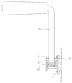
도 1 은 본 고안인 호스 권취장치의 구성을 나타낸 전체 사시도.1 is an overall perspective view showing the configuration of the hose winding device of the present invention.
도 2 는 본 고안인 호스 권취장치의 구성을 나타내기 위한 분해사시도.Figure 2 is an exploded perspective view for showing the configuration of the hose winding device of the present invention.
도 3 은 본 고안인 호스 권취장치의 구성을 나타내기 위한 측단면도.Figure 3 is a side cross-sectional view for showing the configuration of the hose winding device of the present invention.
도 4a 는 본 고안중 회전축멈춤요소의 사용상태를 보인 구성도로서, 회전축이 회전되는 상태도.Figure 4a is a configuration diagram showing a state of use of the rotating shaft stop element of the present invention, a state in which the rotating shaft is rotated.
도 4b 는 본 고안중 회전축멈춤요소의 사용상태를 보인 구성도로서, 회전축이 정지된 상태도.Figure 4b is a configuration diagram showing a state of use of the rotating shaft stop element of the present invention, the rotating shaft is stopped.
도 5a 는 본 고안중 손잡이부를 회동시켜 주는 회동수단을 보인 예시도로서, 손잡이부를 사용하는 상태도.Figure 5a is an exemplary view showing a rotating means for rotating the handle portion of the present invention, a state using the handle portion.
도 5b 는 본 고안중 손잡이부를 회동시켜 주는 회동수단을 보인 예시도로서, 손잡이부를 회동시켜 주기 위한 상태도.Figure 5b is an exemplary view showing a rotation means for rotating the handle portion of the present invention, a state diagram for rotating the handle portion.
도 5c 는 본 고안중 손잡이부를 회동시켜 주는 회동수단을 보인 예시도로서, 손잡이부를 사용하지 않는 상태도.Figure 5c is an exemplary view showing a rotation means for rotating the handle portion of the present invention, a state not using the handle portion.
도면의 주요 부분에 대한 부호설명Explanation of Signs of Major Parts of Drawings
20:권취부 30:회전원판20: winding part 30: rotating disc
31:회전축 32:끼움공31: rotating shaft 32: fitting hole
33:걸림홈 40:브라켓33: locking groove 40: bracket
50:손잡이부 51:걸이핀50: A handle part 51: Hook pin
70:회전축멈춤요소 71:물림편70: rotating shaft stop element 71: entanglement
72:관통공 73:체결편72: Through hole 73: Fastening
75:조임요소 80:탄성요소75: tightening element 80: elastic element
90:받침요소 91:베어링90: support element 91: bearing
본 고안은 임의 길이를 갖는 호스를 감아줄 수 있도록 하는 호스 권취장치에 관한 것으로, 특히 호스가 감겨진 상태 또는 사용하기 위해 소정의 길이를 풀어준 상태에서 호스가 감겨져 있는 보빈이 임의로 회전되지 않아 필요 이상으로 호스가 풀리지 않도록 함과 아울러, 호스의 사용 방향에 따라 보빈의 방향이 자유롭게 회동될 수 있도록 한 호스 권취장치에 관한 것이다.The present invention relates to a hose winding device which can wind a hose having an arbitrary length, and in particular, a bobbin in which the hose is wound in a state in which the hose is wound or a predetermined length is released for use does not need to rotate arbitrarily. The present invention relates to a hose winding device which prevents the hose from being loosened and allows the direction of the bobbin to be freely rotated according to the direction of use of the hose.
일반적으로 호스 권취장치는 사용용도에 따라 각기 다른 길이를 갖는 호스가 감아지도록 하여 보관 및 이동이 용이할 수 있도록 함과 아울러, 임의 길이를 갖고 있는 호스를 사용하고자 할 때 감겨져 있는 호스가 꼬이는 현상이 없이 풀어지도록 하여 호스의 손상됨이 없이 편리하게 취급 사용할 수 있도록 되어 있는 것이다.In general, the hose winding device allows the hoses having different lengths to be wound in accordance with the intended use so that they can be easily stored and moved. In addition, when the hose having any length is used, the wound hose is twisted. It is designed to be easily handled and used without damaging the hose by releasing it.
이러한 종래의 호스 권취장치는 내측 중앙에 호스가 권취될 수 있도록 한 권취부 양측에 회전원판이 갖추어지고, 상기 회전원판의 외측면 중앙에 갖추어진 회 전축이 브라켓에 회전 가능하도록 결합시켜 회전원판이 자유롭게 회전되도록 하여 권취부에 호스가 감기거나 풀릴 수 있도록 되어 있는 것이다.This conventional hose winding device is provided with a rotating disk on both sides of the winding portion so that the hose can be wound in the inner center, the rotating shaft provided in the center of the outer surface of the rotating disk is rotatably coupled to the bracket to rotate the disk The hose can be wound or unwound by winding freely.
이때, 브라켓에 결합 되는 회전축중 일측의 회전축에는 손으로 돌릴 수 있도록 하는 손잡이부가 갖추어지고, 타측의 회전축 중앙에는 관통공을 형성하여 이에 연결용 호스가 결합되는 연결관체가 임의 회전 가능하도록 결합시켜 권취부에 감겨지는 호스의 일단을 연결시켜 주도록 되어 있는 것이다.At this time, one side of the rotating shaft coupled to the bracket is equipped with a handle for turning by hand, the through shaft in the center of the other side of the rotating shaft to form a through-hole to connect the connecting hose to which the hose for connection is coupled to rotate freely It is to connect one end of the hose wound to the mounting.
상기와 같은 구성을 하는 종래의 호스 권취장치는 회전축을 관통한 연결관체의 외측에 연결되어 있는 연결호스를 사용하고자 하는 목적물에 연결 즉, 물을 공급시켜 주고자 할 경우에는 수도꼭지 등에 연결시켜 주면 되는 것이고, 에어를 공급시켜 주고자 할 경우에는 에어펌프에 연결시켜 주면 되는 것이다.The conventional hose winding device having the configuration described above may be connected to a faucet, etc., in order to supply water to a target object to be used, that is, a connection hose connected to an outer side of a connecting pipe passing through a rotating shaft. If you want to supply air, just connect it to the air pump.
상기와 같이 연결호스를 사용하고자 하는 목적물에 연결시켜 준 상태에서 권취부에 감겨져 있는 호스의 선단부를 잡아당겨 주게 되면 호스의 당김력에 의해 회전원판이 회전축을 중심으로 회전하면서 호스가 풀리게 되므로서, 호스의 길이에 의해 허용되는 거리 범위 내에서 호스를 자유롭게 풀어 사용하게 되는 것이고, 호스의 사용이 완료되면 회전원판의 회전축 일측에 갖추어진 손잡이부를 이용하여 회전원판을 돌려주게 되면 풀어져 있는 호스가 권취부에 감겨지게 되므로서, 호스의 용이하게 감아줄 수 있는 것이고, 이로 인해 보관이 용이하게 되어 있는 것이다.Pulling the tip of the hose wound around the winding part in the state that the connection hose is connected to the object to be used as described above, the hose is released while the rotating disc rotates around the rotation axis by the pulling force of the hose, The hose is freely released and used within the distance allowed by the length of the hose. When the hose is used, the loose hose is wound up when the rotating disc is turned by using the handle part provided on one side of the rotating shaft of the rotating disc. As it is wound on, the hose can be easily wound, thereby making it easy to store.
그러나, 상기와 같은 종래의 호스 권취장치는 임의의 길이를 갖고 있는 호스가 꼬이는 현상이 없는 상태로 감아주어 보관 및 취급이 용이하게 되는 것이고, 권취부에 감겨져 있는 호스를 사용하고자 하는 길이만큼 풀어 사용할 수 있는 사용상 의 편리함이 있으나, 호스가 감겨져 있는 회전원판의 회전을 정지시켜 줄 수 있는 기능이 없어 권취부에 감겨져 있는 호스가 임의적으로 풀리는 현상이 있었던 것이다.However, the conventional hose winding device as described above is easy to store and handle by winding the hose having an arbitrary length without twisting phenomenon, and use the hose wound around the winding portion as much as the desired length There is a convenience in use, but there is a function that can stop the rotation of the rotating disk in which the hose is wound, there was a phenomenon that the hose wound around the winding part is released arbitrarily.
이를 좀더 구체적으로 설명하면, 회전원판이 호스의 감김과 풀리는 방향에 따라 자유롭게 회전 가능하도록 되어있어 호스를 감아준 상태에서 보관 및 이동시 회전원판이 임의적으로 회전이 이루어져 감겨져 있는 호스가 풀리는 현상이 있어 이러한 현상을 방지하기 위하여 사용자가 호스의 선단부를 감겨진 호스를 이용하여 임의로 풀리지 않도록 묶어주고 있는 실정이어서, 호스를 풀어주고자 할 경우 풀림을 방지하기 위해 묶여져 있는 호스를 풀어주어야 하는 번거로움이 있는 것이며, 호스의 선단에 물이나 에어가 분사될 수 있도록 하는 분사기가 장착되어 있는 상태에서는 호스를 이용하여 묶어주거나 풀어주기가 더욱더 불편하였던 것이다.In more detail, the rotating disc is freely rotatable according to the winding and unwinding direction of the hose, so that the rotating disc is randomly rotated when the hose is stored and moved while the hose is wound. In order to prevent the phenomenon, the user binds the end of the hose to the hose unwound arbitrarily, so if you want to loosen the hose, it is troublesome to release the bundled hose to prevent loosening In the state where the injector is installed to allow water or air to be injected at the tip of the hose, it was more inconvenient to bind or loosen using the hose.
또한, 권취부에 감겨져 있는 호스중 일부의 호스만 사용하기 위해 소정 길이의 호스를 풀어준 상태에서 사용하게 되는데, 사용도중 호스의 방향을 바꾸어주고자 할 경우, 또는 사용도중 호스를 잡아당겼을 경우에는 호스의 당김력에 의해 회전원판이 회전 되므로서, 필요 이상으로 호스가 풀리게 되는 등의 제반결함이 있었던 것이다.In addition, in order to use only a part of the hose wound around the winding part, it is used while the hose of a predetermined length is released.If you want to change the direction of the hose during use, or when the hose is pulled out during use There was a defect such that the rotating disc is rotated by the pulling force of the hose, the hose is released more than necessary.
그리고, 상기 회전원판을 잡아주는 브라켓이 일체로 제작되어 하단부가 지면에 위치하고 있어 사용도중 호스의 방향을 바꾸어 주고자 할 경우 지면에 안착 되어 있는 브라켓과 회전원판 및 권취부에 감겨져 있는 호스 자체의 중량에 의해 지면에 안착되어 있는 브라켓의 방향을 자유롭게 바꾸어 줄 수 없어 수시로 호스의 방향을 바꾸어 가면서 사용하다 보면 호스가 브라켓에 감기게 됨은 물론, 감기는 과정에서 호스가 꼬이거나 꺾이게 되므로서, 호스가 손상되는 등의 제반결함이 있었던 것이다.In addition, the bracket for holding the rotating disc is integrally formed so that the lower end is positioned on the ground, so that the weight of the bracket itself and the rotating disc wound on the ground and the winding portion of the hose itself are wound on the ground to change the direction of the hose during use. It is not possible to freely change the direction of the bracket seated on the ground by using the hose while changing the direction of the hose from time to time. There are many defects such as being.
따라서, 본 고안의 목적은 회전체의 중앙에 갖추어진 권취부에 감겨져 있는 호오스가 임의로 풀리지 않도록 함과 아울러, 사용하고자 하는 길이만큼 풀어준 상태에서 사용하는 도중에도 더 이상 풀리는 일이 없도록 하므로서, 보관 및 취급이 용이할 수 있도록 하는데 그 목적이 있는 것이다.Therefore, the object of the present invention is to ensure that the hose wound around the winding part provided in the center of the rotating body is not released at random, and that it is no longer released during use in the state of being released by the desired length. And its purpose is to facilitate handling.
본 고안의 다른 목적은 회전원판을 잡아주고 있는 브라켓의 방향이 자유롭게 바뀌어질 수 있도록 하여 사용도중 풀어져 있는 호스가 브라켓에 감기는 현상이 없도록 하여 이로 인한 꼬임 및 꺾이는 현상으로 인한 손상이 없는 상태에서 사용할 수 있도록 하는데 그 목적이 있는 것이다.Another object of the present invention is to allow the direction of the bracket holding the rotating disc to be freely changed so that the hose is not wound around the bracket during use, so that it can be used in a state without damage due to the kink and bending caused by this. The purpose is to make it possible.
이러한 목적을 실현하기 위한 본 고안은 호스가 감기는 권취부 양측에 호스의 이탈을 방지하는 회전원판을 갖추고, 상기 회전원판 외측 중앙에 갖추어진 회전축이 회전 가능하도록 결합 되는 브라켓을 갖추며, 상기 회전축에는 손잡이부와 연결호스가 결합된 회전관체로 이루어지는 호스 권취장치를 형성함에 있어,The present invention for realizing this purpose is provided with a rotating disk to prevent the separation of the hose on both sides of the winding portion that the hose is wound, equipped with a bracket that is rotatably coupled to the rotating shaft provided in the outer center of the rotating disk, In forming a hose winding device consisting of a rotary tube coupled to the handle portion and the connection hose,
상기 회전축의 외주연에 감싸지는 상태로 일측이 브라켓에 고정되어 회전축의 회전을 정지시켜 줄 수 있도록 하는 회전축멈춤요소가 갖추어진 것을 특징으로 하는 것이다.One side is fixed to the bracket in a state wrapped around the outer periphery of the rotary shaft is characterized in that the rotary shaft stopping element for stopping the rotation of the rotary shaft is provided.
또한, 상기 회전축멈춤요소는 회전축의 외주연에 씌워질 수 있도록 관통공을 갖고 일측이 절개된 물림편을 갖추고, 상기 절개지점을 기점으로 하여 일체로 연장되는 나선공을 갖춘 체결편을 갖추며, 상기 체결편을 나선공에 나선체결되어 나선 체결 방향에 따라 물림편이 조여지거나 벌어질 수 있도록 하는 조임요소로 이루어진 것을 특징으로 하는 것이다.In addition, the rotating shaft stop element is provided with a fastening piece having a through hole so as to be covered on the outer periphery of the rotating shaft, one side is cut, and has a fastening piece having a spiral hole integrally extending from the cutting point as a starting point, It is characterized in that the fastening piece is made of a fastening element to be fastened or unfastened bite pieces according to the direction of the fastening of the spiral by fastening the fastening piece to the spiral hole.
또한, 상기 회전축에 갖추어진 손잡이부를 사용용도에 따라 회동 가능하도록 하는 회동수단이 더 포함된 것을 특징으로 하는 것이다.In addition, it is characterized in that it further comprises a rotation means for allowing the handle portion provided on the rotating shaft to be rotatable in accordance with the intended use.
또한, 상기 회동수단은 회전축에 손잡이부의 끝단부가 끼워져 관통할 수 있도록 하는 끼움공을 갖추고, 상기 끼움공에 끼워지는 손잡이부 끼움축에 씌워진 상태로 하여 끼움공과 체결요소에 탄지되는 탄성요소를 갖추며, 상기 끼움공의 상면 외주연에 직각을 이루는 걸림홈을 갖추고 있으며, 손잡이부에는 상기 걸림홈에 걸릴 수 있도록 하는 걸이핀으로 이루어진 것을 특징으로 하는 것이다.In addition, the rotation means is provided with a fitting hole to allow the end of the handle portion to be inserted through the rotating shaft, and is provided with an elastic element supported on the fitting hole and the fastening element in a state covered by the handle portion fitting shaft fitted to the fitting hole, It has a locking groove forming a right angle to the outer periphery of the upper surface of the fitting hole, characterized in that the handle portion made of a hook pin to be caught in the locking groove.
또한, 상기 브라켓의 하부에 베어링에 의해 회전 가능하도록 하는 받침요소가 더 포함된 것을 특징으로 하는 것이다.In addition, the lower portion of the bracket is characterized in that it further comprises a support element to be rotatable by the bearing.
이하, 첨부된 도면에 의해 본 고안 실시예의 구성을 설명하면 다음과 같다.Hereinafter, the configuration of the present invention by the accompanying drawings will be described.
도 1 은 본 고안이 적용된 호스 권취장치의 구성을 나타낸 전체 사시도이고, 도 2 는 본 고안인 호스 권취장치의 구성을 나타내기 위한 요부 확대 분해사시도이며, 도 3 은 본 고안인 호스 권취장치의 구성을 나타내기 위한 결합 단면도로서, 본 고안인 호스 권취장치(10)는 호스가 감겨질 수 있도록 하는 권취부(20) 양측에 감겨지는 호스의 이탈을 잡아주는 회전원판(30)이 갖추어진다.1 is an overall perspective view showing the configuration of the hose winding device to which the present invention is applied, Figure 2 is an enlarged exploded perspective view of the main portion for showing the configuration of the hose winding device of the present invention, Figure 3 is a configuration of the hose winding device of the present invention As a combined cross-sectional view for showing, the present invention
상기 회전원판은 외측면 중앙에 갖추어진 회전축(31)을 브라켓(40)에 회전 가능하도록 결합시켜 회전원판이 자유롭게 회전되도록 하여 권취부에 호스가 감기거나 풀릴 수 있도록 한다.The rotating disc is rotatably coupled to the rotating
이때, 브라켓에 결합 되는 회전축중 일측의 회전축에는 손으로 돌릴 수 있도록 하는 손잡이부(50)가 갖추어지고, 타측의 회전축(31)은 중앙에 관통공(도시되지 않음)을 형성시켜 내측 부분으로 권취부에 감겨지는 호스(1)가 연결되는 연결리플(60)이 갖추어지며, 상기 회전축의 외측 외주연에는 임의 회전 가능하도록 한 상태에서 연결호스(1a)가 연결된 회전관체(60a)를 갖추어 회전축이 회전하더라도 회전관체는 회전하지 않아 연결호스가 꼬이는 현상이 발생하지 않도록 한다.At this time, one of the rotating shafts coupled to the bracket is provided with a
상기와 같은 구성으로 하는 호스 권취장치는 종래와 동일한 구성이며, 다만 본 고안에서는 회전축(50)의 외주연을 감싸는 상태로 브라켓(40)에 결합시켜 상기 회전축(50)의 회전과 멈춤을 수행시켜 줄 수 있도록 하는 회전축멈춤요소(70)를 갖추어준 것이다.Hose winding device having the configuration as described above is the same configuration as in the prior art, but in the present invention is coupled to the
상기 회전축멈춤요소(70)는 회전축(31)이 긴밀하게 관통할 수 있도록 중앙에 관통공(72)을 갖추고, 일단이 브라켓(40)과 체결 고정되는 물림편(71)을 갖추되, 상기 물림편의 일측을 절개시켜 절개면에 의해 물림편이 벌어지도록 하여 관통공을 관통하는 회전축이 자유롭게 회전 가능하도록 한다.The rotary
또한, 상기 절개면의 외측으로는 각각 나선공(74)을 갖추고 있는 체결편(73)을 갖추며, 상기 체결편의 나선공에 나선체결되어 회전 방향에 따라 관통공을 조여주거나 벌어질 수 있도록 하는 조임요소(75)로 이루어진다.In addition, the outer side of the cutting surface is provided with a fastening piece (73) having a
즉, 권취부(20)에 감겨져 있는 호스(1)를 풀어주거나 풀어져 있는 호스를 권취부에 감아주고자 할 경우 도 4a 에 도시된 바와 같이 체결편(73)의 나선공(74)에 나선 체결되어 있는 조임요소(75)를 풀어주게 되면 체결편(73)이 벌어짐에 따라 회전축(31) 외주연에 감싸여져 있는 관통공(72)이 회전축으로부터 이격 된 상태에 있게 된다.That is, in the case of releasing the
상기와 같이 관통공 내주면이 회전축으로부터 이격 되어 있으므로서, 회전축의 회전이 자유롭게 이루어짐에 따라 권취부(20)에 감겨져 있는 호스를 원활히 풀어주게 됨은 물론, 풀어져 있는 호스를 권취부에 감겨주게 되는 것이다.Since the inner circumferential surface of the through hole is spaced apart from the rotation shaft as described above, as the rotation shaft is freely rotated, the hose wound around the winding
상기와 같이 권취부(20)에 호스가 완전히 감겨지거나, 사용하고자 하는 길이만큼 호스를 풀어주었을 경우에는 도 4b 에 도시된 바와 같이 느슨하게 풀어져 있는 조임요소(75)를 돌려 체결편(73)을 나선 체결시켜 주게 되면 소정의 간격으로 벌어져 있는 체결편(73)이 밀착됨에 따라 관통공(72)의 내주면이 회전축(31)을 긴밀하게 면접촉되므로서, 상기 회전축의 회전을 잡아주게 되는 것으로서, 권취부에 감겨져 있는 호스가 임의로 풀어지는 일이 없게 되는 것이며, 호스를 사용할 때 필요한 길이만큼 풀어준 상태에서 사용도중 호스를 잡아당기더라도 더 이상 풀리지 않는 상태에서 사용하게 되는 것이다.When the hose is completely wound around the
그리고, 상기 호스를 감거나 풀어주기 위해 회전원판(30)을 회전시켜 주기 위하여 회전축(31)의 일측에 갖추어져 있는 손잡이부(50)를 회전축(31) 일측에 갖추어진 끼움공(32)에 탄성요소(80)가 탄지 되도록 결합시켜 주고, 상기 끼움공의 외주연에 직각을 유지하는 걸림홈(33)을 갖추고, 손잡이부에 상기 걸림홈에 끼워져 걸릴수 있도록 하는 걸이핀(51)을 갖추어 손잡이부(50)를 회동시켜 줄 수 있도록 한다.And, in order to rotate the rotating
즉, 호스 권취장치(10)를 사용하지 않고 보관 및 이동시에는 도 5a 에 도시된 바와 같이 손잡이부(50)가 브라켓(40)과 동일선상에 위치하도록 하여 손잡이부가 외측으로 돌출됨이 없어 보관이 용이함은 물론, 보관과 사용도중 손잡이부가 외측으로 돌출되지 주변을 지나치는 사람이 걸리는 일이 없도록 하는 것이고, 호스를 감아주거나 풀어주고자 할 경우에는 도 5b 에 도시된 바와 같이 손잡이부(50)를 상부로 잡아당겨 주게 되면 탄성요소(80)가 압축되면서 상부로 이동하여 걸이핀(51)이 걸림홈(33)으로부터 이격되면 상기 손잡이부(50)를 90°로 회동시켜 도 5c 에 도시된 바와 같이 다른 걸림홈(32)에 걸이핀(51)이 걸리도록 한 상태에서 상기 손잡이부를 돌려주어 호스를 감거나 풀어주도록 되어 있는 것이다.That is, when storing and moving without using the
또한, 상기 브라켓(40)의 하부에 베어링(91)에 의해 결합시켜 임의 회전이 가능하도록 하는 받침요소(90)를 갖추어 브라켓(40)이 임의 회동 가능하도록 한다.In addition, the lower portion of the
즉, 브라켓(40)의 하부에 임의 회동이 가능한 받침요소(90)가 갖추어져 있어 브라켓이 지면에 안착되지 않고 받침요소(90)가 안착되므로서, 이의 상부에 위치하고 있는 브라켓(40)은 베어링(91)에 의해 임의 회동이 가능하게 되는 것이다.That is, the
따라서, 사용하고자 하는 길이만큼 호스를 풀어 놓은 상태에서 호스를 사용하다가 상기 호스의 방향을 바꾸어주게 되면 호스의 이동 위치에 따라 브라켓(40)이 함께 회동을 수행하므로서, 호스(1)가 브라켓(40)에 감기거나 꼬이는 현상이 없이 사용을 할 수 있는 것이다.Therefore, when the hose is used in the state in which the hose is released by the length to be used and the direction of the hose is changed, the
이상에서와 같이 본 고안은 회전축의 외주연에 임의 회전을 정지시켜 줄 수 있는 회전축멈춤요소를 갖추어 주므로서, 보관 및 이동시 그리고, 호스를 풀어 사용시 회전원판이 임의적으로 회전되지 않도록 하여 호스가 임의적으로 풀리지 않도록 한 상태에서 편리하게 취급 및 사용할 수 있게 되는 효과가 있는 것이고, 회전축의 일측에 갖추어져 회전원판을 회전시켜 줄 수 있는 손잡이부를 회전축과 일체로 갖추어지지 않고, 회전 가능하도록 하여 상기 손잡이부를 사용하지 않을 때 손잡이부가 회전축과 직각이 되도록 하여 보관 및 이동시 외측으로 돌출되는 손잡이부에 걸리는 일이 없어 안전사고를 사전에 예방할 수 있게 되는 효과가 있는 것이다.As described above, the present invention is equipped with a rotating shaft stop element that can stop arbitrary rotation on the outer circumference of the rotating shaft, so that the rotating disc does not rotate randomly during storage and movement, and when the hose is released and the hose is arbitrarily rotated. There is an effect that it can be conveniently handled and used in a state that does not loosen, and is provided on one side of the rotating shaft to be rotatable without being provided integrally with the rotating shaft, so as to be rotatable. When the handle is not perpendicular to the axis of rotation when the handle is not caught in the handle protruding outward during storage and movement is to prevent the safety accident in advance.
또한, 상기 회전원판을 잡아주는 브라켓의 하부에 베어링에 의해 회전 가능하도록 하는 받침요소를 갖추어 호스를 사용도중 호스의 방향이 바뀔 경우 호스의 방향에 따라 받침요소 상면에 베어링에 의해 결합된 브라켓이 자유롭게 회전을 수행함에 따라 호스가 꼬이거나 꺾이는 현상이 없이 편리하게 사용할 수 있게 되는 등의 효과가 있는 것이다.In addition, the lower part of the bracket for holding the rotating disc is provided with a support element to be rotatable by the bearing, if the direction of the hose changes during use of the hose, the bracket coupled by the bearing on the upper surface of the support element according to the direction of the hose freely As the rotation is performed, there is an effect such that the hose can be conveniently used without being twisted or bent.
Claims (5)
Priority Applications (1)
| Application Number | Priority Date | Filing Date | Title |
|---|---|---|---|
| KR2020060010820U KR200424924Y1 (en) | 2006-04-21 | 2006-04-21 | Hose Winding Device |
Applications Claiming Priority (1)
| Application Number | Priority Date | Filing Date | Title |
|---|---|---|---|
| KR2020060010820U KR200424924Y1 (en) | 2006-04-21 | 2006-04-21 | Hose Winding Device |
Publications (1)
| Publication Number | Publication Date |
|---|---|
| KR200424924Y1 true KR200424924Y1 (en) | 2006-08-29 |
Family
ID=41773512
Family Applications (1)
| Application Number | Title | Priority Date | Filing Date |
|---|---|---|---|
| KR2020060010820U Expired - Lifetime KR200424924Y1 (en) | 2006-04-21 | 2006-04-21 | Hose Winding Device |
Country Status (1)
| Country | Link |
|---|---|
| KR (1) | KR200424924Y1 (en) |
Cited By (1)
| Publication number | Priority date | Publication date | Assignee | Title |
|---|---|---|---|---|
| KR101193529B1 (en) * | 2010-06-29 | 2012-10-22 | 주식회사 릴텍산업 | Hose-reel having idling break control system |
-
2006
- 2006-04-21 KR KR2020060010820U patent/KR200424924Y1/en not_active Expired - Lifetime
Cited By (1)
| Publication number | Priority date | Publication date | Assignee | Title |
|---|---|---|---|---|
| KR101193529B1 (en) * | 2010-06-29 | 2012-10-22 | 주식회사 릴텍산업 | Hose-reel having idling break control system |
Similar Documents
| Publication | Publication Date | Title |
|---|---|---|
| JP2024023336A5 (en) | ||
| US8863921B2 (en) | 360-degree freedom electric cord device and system | |
| US8684390B1 (en) | Retractable tow strap apparatus | |
| US20100044490A1 (en) | Hand held cable reel | |
| US8561951B2 (en) | Garden hose guide | |
| US8827198B1 (en) | Fishing line unwinder | |
| KR101927469B1 (en) | fire hose reel apparatus for hydrant | |
| US11758902B2 (en) | Retractable duck decoy weight | |
| TWI700424B (en) | Roll control dual-purpose dual-pipe device | |
| EP0681429A1 (en) | WINDING-FREE CONNECTING DEVICE. | |
| TW201144201A (en) | Hose reel frame and guide arm | |
| EP1165423B1 (en) | Box-like dispenser with a supporting device for a reel with a wound-on electrical cord or similar rope-like element, which can be unreeled from the dispenser | |
| US20050230057A1 (en) | Hand tool for holding a tape spool | |
| JP6259901B1 (en) | Wire feeder | |
| US8544784B2 (en) | Line tightening device | |
| US5100077A (en) | Unwinding reel | |
| KR200373378Y1 (en) | Hose winder for agriculfural chenicals | |
| US1261505A (en) | Clothes-line tightener. | |
| JP2005350243A (en) | Device for winding long-size material such as hose | |
| KR200320797Y1 (en) | Rotating control device of electric cord reel | |
| KR102513785B1 (en) | Tension knob separation prevention reel | |
| KR20100003679U (en) | Rotary reel unit | |
| KR102110713B1 (en) | firehose winder | |
| GB2418653A (en) | Lead tensioning and retraction device | |
| US20170002584A1 (en) | Handheld Spooling Device |
Legal Events
| Date | Code | Title | Description |
|---|---|---|---|
| UA0108 | Application for utility model registration |
Comment text: Application for Utility Model Registration Patent event code: UA01011R08D Patent event date: 20060421 |
|
| REGI | Registration of establishment | ||
| UR0701 | Registration of establishment |
Patent event date: 20060822 Patent event code: UR07011E01D Comment text: Registration of Establishment |
|
| UR1002 | Payment of registration fee |
Start annual number: 1 End annual number: 1 Payment date: 20060424 |
|
| UG1601 | Publication of registration | ||
| UR1001 | Payment of annual fee |
Payment date: 20070727 Start annual number: 2 End annual number: 3 |
|
| UR1001 | Payment of annual fee |
Payment date: 20090717 Start annual number: 4 End annual number: 4 |
|
| UR1001 | Payment of annual fee |
Payment date: 20101022 Start annual number: 5 End annual number: 5 |
|
| UR1001 | Payment of annual fee |
Payment date: 20110822 Start annual number: 6 End annual number: 6 |
|
| FPAY | Annual fee payment |
Payment date: 20120905 Year of fee payment: 7 |
|
| UR1001 | Payment of annual fee |
Payment date: 20120905 Start annual number: 7 End annual number: 7 |
|
| FPAY | Annual fee payment |
Payment date: 20130822 Year of fee payment: 8 |
|
| UR1001 | Payment of annual fee |
Payment date: 20130822 Start annual number: 8 End annual number: 8 |
|
| FPAY | Annual fee payment |
Payment date: 20140822 Year of fee payment: 9 |
|
| UR1001 | Payment of annual fee |
Payment date: 20140822 Start annual number: 9 End annual number: 9 |
|
| FPAY | Annual fee payment |
Payment date: 20150824 Year of fee payment: 10 |
|
| UR1001 | Payment of annual fee |
Payment date: 20150824 Start annual number: 10 End annual number: 10 |
|
| EXPY | Expiration of term | ||
| UC1801 | Expiration of term |
Termination category: Expiration of duration Termination date: 20161021 |