KR20090077145A - Near-field optical recording / reproducing apparatus and gap error signal normalization method of the apparatus - Google Patents
Near-field optical recording / reproducing apparatus and gap error signal normalization method of the apparatus Download PDFInfo
- Publication number
- KR20090077145A KR20090077145A KR1020080002929A KR20080002929A KR20090077145A KR 20090077145 A KR20090077145 A KR 20090077145A KR 1020080002929 A KR1020080002929 A KR 1020080002929A KR 20080002929 A KR20080002929 A KR 20080002929A KR 20090077145 A KR20090077145 A KR 20090077145A
- Authority
- KR
- South Korea
- Prior art keywords
- error signal
- gap error
- magnitude
- light source
- gap
- Prior art date
- Legal status (The legal status is an assumption and is not a legal conclusion. Google has not performed a legal analysis and makes no representation as to the accuracy of the status listed.)
- Withdrawn
Links
Images


Classifications
-
- G—PHYSICS
- G11—INFORMATION STORAGE
- G11B—INFORMATION STORAGE BASED ON RELATIVE MOVEMENT BETWEEN RECORD CARRIER AND TRANSDUCER
- G11B7/00—Recording or reproducing by optical means, e.g. recording using a thermal beam of optical radiation by modifying optical properties or the physical structure, reproducing using an optical beam at lower power by sensing optical properties; Record carriers therefor
- G11B7/08—Disposition or mounting of heads or light sources relatively to record carriers
- G11B7/09—Disposition or mounting of heads or light sources relatively to record carriers with provision for moving the light beam or focus plane for the purpose of maintaining alignment of the light beam relative to the record carrier during transducing operation, e.g. to compensate for surface irregularities of the latter or for track following
-
- G—PHYSICS
- G11—INFORMATION STORAGE
- G11B—INFORMATION STORAGE BASED ON RELATIVE MOVEMENT BETWEEN RECORD CARRIER AND TRANSDUCER
- G11B7/00—Recording or reproducing by optical means, e.g. recording using a thermal beam of optical radiation by modifying optical properties or the physical structure, reproducing using an optical beam at lower power by sensing optical properties; Record carriers therefor
- G11B7/12—Heads, e.g. forming of the optical beam spot or modulation of the optical beam
- G11B7/135—Means for guiding the beam from the source to the record carrier or from the record carrier to the detector
- G11B7/1387—Means for guiding the beam from the source to the record carrier or from the record carrier to the detector using the near-field effect
-
- G—PHYSICS
- G11—INFORMATION STORAGE
- G11B—INFORMATION STORAGE BASED ON RELATIVE MOVEMENT BETWEEN RECORD CARRIER AND TRANSDUCER
- G11B7/00—Recording or reproducing by optical means, e.g. recording using a thermal beam of optical radiation by modifying optical properties or the physical structure, reproducing using an optical beam at lower power by sensing optical properties; Record carriers therefor
- G11B7/08—Disposition or mounting of heads or light sources relatively to record carriers
- G11B7/09—Disposition or mounting of heads or light sources relatively to record carriers with provision for moving the light beam or focus plane for the purpose of maintaining alignment of the light beam relative to the record carrier during transducing operation, e.g. to compensate for surface irregularities of the latter or for track following
- G11B7/0908—Disposition or mounting of heads or light sources relatively to record carriers with provision for moving the light beam or focus plane for the purpose of maintaining alignment of the light beam relative to the record carrier during transducing operation, e.g. to compensate for surface irregularities of the latter or for track following for focusing only
-
- G—PHYSICS
- G11—INFORMATION STORAGE
- G11B—INFORMATION STORAGE BASED ON RELATIVE MOVEMENT BETWEEN RECORD CARRIER AND TRANSDUCER
- G11B7/00—Recording or reproducing by optical means, e.g. recording using a thermal beam of optical radiation by modifying optical properties or the physical structure, reproducing using an optical beam at lower power by sensing optical properties; Record carriers therefor
- G11B7/08—Disposition or mounting of heads or light sources relatively to record carriers
- G11B7/09—Disposition or mounting of heads or light sources relatively to record carriers with provision for moving the light beam or focus plane for the purpose of maintaining alignment of the light beam relative to the record carrier during transducing operation, e.g. to compensate for surface irregularities of the latter or for track following
- G11B7/0941—Methods and circuits for servo gain or phase compensation during operation
Landscapes
- Physics & Mathematics (AREA)
- Optics & Photonics (AREA)
- Optical Head (AREA)
- Optical Recording Or Reproduction (AREA)
Abstract
본 발명은 갭 에러 신호를 정규화함으로써 기록 및 재생시에 갭 에러 신호를 일정하게 유지할 수 있는 근접장 광기록/재생 장치 및 상기 장치의 갭 에러 신호 정규화 방법에 관한 것이다. 본 발명의 예시적인 실시예에 따른 근접장 광기록/재생 장치는, 광원; 상기 광원에서 방출된 광을 집광하여 스폿을 형성하는 대물렌즈; 상기 대물렌즈에 의해 형성된 스폿을 이용하여 소멸파를 발생시키는 고체함침렌즈; 상기 고체함침렌즈로부터 전반사된 갭 에러 신호의 크기를 측정하는 광검출기; 및 상기 광원으로 인가되는 구동 신호의 크기 및 상기 광검출기에서 측정된 갭 에러 신호의 크기를 이용하여 정규화된 갭 에러 신호를 생성하는 연산부;를 포함하는 것을 특징으로 한다.The present invention relates to a near field optical recording / reproducing apparatus capable of keeping a gap error signal constant during recording and reproduction by normalizing the gap error signal, and a gap error signal normalization method of the apparatus. A near field optical recording / reproducing apparatus according to an exemplary embodiment of the present invention, includes: a light source; An objective lens condensing the light emitted from the light source to form a spot; A solid impregnation lens for generating an evanescent wave by using a spot formed by the objective lens; A photodetector measuring a magnitude of a gap error signal totally reflected from the solid impregnation lens; And a calculator configured to generate a normalized gap error signal using the magnitude of the driving signal applied to the light source and the magnitude of the gap error signal measured by the photodetector.
Description
본 발명은 근접장 광기록/재생 장치 및 상기 장치의 갭 에러 신호 정규화 방법에 관한 것으로, 보다 상세하게는, 갭 에러 신호를 정규화함으로써 기록 및 재생시에 갭 에러 신호를 일정하게 유지할 수 있는 근접장 광기록/재생 장치 및 갭 에러 신호 정규화 방법에 관한 것이다.The present invention relates to a near field optical recording / reproducing apparatus and a method of normalizing a gap error signal of the apparatus, and more particularly, to a near field optical recording / reproducing that can keep a gap error signal constant during recording and reproduction by normalizing a gap error signal. A playback apparatus and gap error signal normalization method.
광디스크와 같은 광기록 매체에 정보를 저장하는 기술은 지속적으로 발전하여, CD, DVD에 이어 현재 BD(Blu-ray Disc)와 HD-DVD가 상용화되고 있다. 이러한 CD, DVD, BD, HD-DVD 등과 같이 지금까지 상용화된 기술은 광헤드로부터 광디스크의 기록면까지의 거리가 1~2mm 정도인 원격장(far-field) 저장 기술이다. 원격장 저장 기술의 경우, 광의 파장을 짧게 하고 대물렌즈의 개구수를 증대시키더라도, 빛의 회절 현상으로 인하여 광디스크의 기록면에 형성되는 광스폿의 크기를 줄이는 데 한계가 있어서 더 이상 기록용량을 증가시키가 어렵다.The technology of storing information on an optical recording medium such as an optical disc has been continuously developed, and BD (Blu-ray Disc) and HD-DVD are commercially available after CD and DVD. The technologies commercialized so far, such as CD, DVD, BD, HD-DVD, and the like, are far-field storage technologies having a distance of 1 to 2 mm from the optical head to the recording surface of the optical disk. In the case of the remote field storage technology, even if the wavelength of the light is shortened and the numerical aperture of the objective lens is increased, there is a limit in reducing the size of the optical spot formed on the recording surface of the optical disc due to the diffraction phenomenon of the light. Difficult to make
이에 따라, 최근에는 테라바이트 이상의 큰 기록용량을 가질 수 있는 근접 장(near-field) 기술을 이용한 광기록/재생 장치에 대한 관심이 높아지고 있다. 근접장 광기록/재생 기술의 경우, 광헤드로부터 광디스크 기록면까지의 거리를 100nm 이하로 단축함으로써, 광 파장의 수분의 일에 해당되는 매우 좁은 영역에서 발생하는 소멸파(evanescent wave)를 광디스크에 전달하여 기록 및 재생을 수행한다. 예컨대, 고체함침렌즈(solid immersion lens; SIL)를 이용하는 근접장 광기록/재생 기술의 경우, 대물렌즈가 입사빔을 수렴시켜 고체함침렌즈(SIL)의 표면에 스폿을 형성하면, 이 스폿은 고체함침렌즈에 의해 상당 부분 전반사되어 되돌아 간다. 이때, 전반사에 의해서 고체함침렌즈의 표면에는 아주 미세한 세기의 광이 존재하는 데, 이를 소멸파(evanescent wave)라고 한다. 이렇게 형성된 소멸파의 에너지를 고체함침렌즈와 광디스크 사이의 좁은 에어갭을 통해 광디스크로 전달함으로써 광디스크에 대한 정보의 재생 또는 기록이 수행될 수 있다.Accordingly, in recent years, there has been a growing interest in optical recording / reproducing apparatus using near-field technology, which can have a large recording capacity of more than terabytes. In the near field optical recording / reproducing technology, the distance from the optical head to the optical disk recording surface is shortened to 100 nm or less, thereby transmitting an evanescent wave generated in a very narrow region corresponding to the work of moisture of the optical wavelength to the optical disk. Perform recording and playback. For example, in the near field optical recording / reproducing technique using a solid immersion lens (SIL), when the objective lens converges an incident beam to form a spot on the surface of the solid immersion lens (SIL), the spot is solid impregnated. It is totally reflected by the lens and returns. In this case, light of very fine intensity exists on the surface of the solid impregnated lens due to total reflection, which is called an evanescent wave. The energy of the evanescent wave thus formed is transferred to the optical disc through a narrow air gap between the solid impregnation lens and the optical disc, so that the reproduction or recording of information on the optical disc can be performed.
이러한 근접장 기술에서 기록 및 재생 품질을 최적화하기 위해서는 고체함침렌즈와 광디스크 사이의 거리를 일정하게 유지하는 것이 중요하다. 통상적으로 고체함침렌즈와 광디스크 사이의 거리는 상기 고체함침렌즈로부터 전반사되어 되돌아가는 광의 세기를 측정하여 구할 수 있다. 즉, 원격장 상태에서는 고체함침렌즈에 의해 전반사되는 광량이 최대가 되며, 근접장 상태에서 고체함침렌즈와 광디스크 사이의 거리가 가까워질수록 전반사되는 광량이 작아진다는 점을 이용한다. 여기서, 상기 고체함침렌즈에 의해 전반사되어 되돌아오는 광 신호를 일반적으로 갭 에러 신호(gap error signal; GES)라고 부른다. 따라서, 갭 에러 신호(GES)의 크기로부터 고체함침렌즈와 광디스크 사이의 거리를 추정할 수 있다. 예컨대, 원격장 상 태에서의 갭 에러 신호(GES)의 레벨을 1V라고 하고 고체함침렌즈가 광디스크와 완전히 접촉하였을 때의 갭 에러 신호(GES)의 레벨을 0V라고 정할 때, 상기 갭 에러 신호(GES)의 레벨이 0.5V가 되면 고체함침렌즈와 광디스크 사이의 거리를 50nm 정도라고 볼 수 있다.In this near field technology, it is important to keep the distance between the solid-impregnated lens and the optical disk constant to optimize recording and playback quality. Typically, the distance between the solid impregnation lens and the optical disk can be obtained by measuring the intensity of light returned totally reflected from the solid impregnation lens. That is, the maximum amount of light totally reflected by the solid-impregnated lens in the far field state is maximized, and the closer the distance between the solid-impregnated lens and the optical disk in the near-field state is, the smaller the total amount of light is reflected. Here, the optical signal totally reflected by the solid-impregnated lens and returned is generally referred to as a gap error signal (GES). Therefore, the distance between the solid-impregnated lens and the optical disk can be estimated from the magnitude of the gap error signal GES. For example, when the level of the gap error signal GES in the remote field state is 1V and the level of the gap error signal GES when the solid-impregnated lens is in full contact with the optical disk is 0V, the gap error signal ( When the level of the GES) is 0.5V, the distance between the solid-impregnated lens and the optical disk is about 50 nm.
그런데, 갭 에러 신호(GES)의 크기는 광원으로부터 제공되는 광의 세기에 의해서도 영향을 받기 때문에, 광원을 구동하기 위한 구동 신호의 세기가 변화하게 되면 고체함침렌즈와 광디스크 사이의 거리를 정확하게 측정하는 것이 곤란하게 된다. 특히, 기록시의 광세기는 재생시의 광세기에 비하여 10배 정도 크기 때문에, 갭 에러 신호(GES)의 크기도 기록시와 재생시에 크게 달라지게 된다. 따라서, 기록모드에서 재생모드로 전환할 때 또는 재생모드에서 기록모드로 전환할 때 상기 고체함침렌즈와 광디스크 사이의 거리를 일정하게 유지하기 위해서는, 광원의 구동 신호의 세기와 관계 없이 갭 에러 신호(GES)가 일정하게 될 수 있도록 정규화시키는 것이 필요하다.However, since the magnitude of the gap error signal GES is also influenced by the intensity of the light provided from the light source, when the intensity of the driving signal for driving the light source changes, it is necessary to accurately measure the distance between the solid-impregnated lens and the optical disk. It becomes difficult. In particular, since the light intensity at the time of recording is about 10 times larger than the light intensity at the time of reproduction, the magnitude of the gap error signal GES also varies greatly during recording and reproduction. Therefore, in order to keep the distance between the solid-impregnated lens and the optical disc constant when switching from the recording mode to the playback mode or when switching from the playback mode to the recording mode, the gap error signal (regardless of the intensity of the drive signal of the light source) It is necessary to normalize so that GES) can be constant.
본 발명의 목적은 상술한 갭 에러 신호(GES)를 정규화함으로써 기록 및 재생시에 갭 에러 신호를 일정하게 유지할 수 있는 근접장 광기록/재생 장치 및 상기 장치의 갭 에러 신호 정규화 방법을 제공하는 것이다.It is an object of the present invention to provide a near field optical recording / reproducing apparatus capable of maintaining a constant gap error signal during recording and reproduction by normalizing the above-described gap error signal GES and a gap error signal normalization method of the apparatus.
본 발명의 예시적인 실시예에 따른 근접장 광기록/재생 장치는, 광원; 상기 광원에서 방출된 광을 집광하여 스폿을 형성하는 대물렌즈; 상기 대물렌즈에 의해 형성된 스폿을 이용하여 소멸파를 발생시키는 고체함침렌즈; 상기 고체함침렌즈로부터 전반사된 갭 에러 신호의 크기를 측정하는 광검출기; 및 상기 광원으로 인가되는 구동 신호의 크기 및 상기 광검출기에서 측정된 갭 에러 신호의 크기를 이용하여 정규화된 갭 에러 신호를 생성하는 연산부;를 포함하는 것을 특징으로 한다.A near field optical recording / reproducing apparatus according to an exemplary embodiment of the present invention, includes: a light source; An objective lens condensing the light emitted from the light source to form a spot; A solid impregnation lens for generating an evanescent wave by using a spot formed by the objective lens; A photodetector measuring a magnitude of a gap error signal totally reflected from the solid impregnation lens; And a calculator configured to generate a normalized gap error signal using the magnitude of the driving signal applied to the light source and the magnitude of the gap error signal measured by the photodetector.
본 발명에 따르면, 상기 연산부는 원격장 상태에서 측정한 구동 신호의 크기를 원격장 상태에서 측정한 갭 에러 신호의 크기로 나누어 정규화 팩터를 계산할 수 있다.According to the present invention, the operation unit may calculate a normalization factor by dividing the magnitude of the driving signal measured in the far-field state by the magnitude of the gap error signal measured in the far-field state.
또한, 상기 연산부는 재생 또는 기록 동작시에 측정한 갭 에러 신호의 크기를 재생 또는 기록 동작시에 측정한 구동 신호의 크기로 나누고, 여기에 상기 정규화 팩터를 곱함으로써 정규화된 갭 에러 신호를 생성할 수 있다.The operation unit may generate a normalized gap error signal by dividing the magnitude of the gap error signal measured in the reproduction or recording operation by the magnitude of the driving signal measured in the reproduction or recording operation, and multiplying the normalization factor. Can be.
본 발명에 따른 상기 근접장 광기록/재생 장치는, 상기 광원과 연산부 사이에 배치되어 상기 연산부에 제공되는 구동 신호의 고주파 성분을 제거하는 제 1 저 역통과필터; 및 상기 광검출기와 연산부 사이에 배치되어 상기 연산부에 제공되는 갭 에러 신호의 고주파 성분을 제거하는 제 2 저역통과필터;를 더 포함할 수 있다.The near field optical recording / reproducing apparatus according to the present invention includes: a first low pass filter disposed between the light source and the computing unit to remove high frequency components of a driving signal provided to the computing unit; And a second low pass filter disposed between the photodetector and the calculator to remove a high frequency component of a gap error signal provided to the calculator.
또한, 본 발명에 따른 상기 근접장 광기록/재생 장치는, 상기 대물렌즈 및 고체함침렌즈를 탑재하는 것으로, 상기 연산부에서 제공되는 정규화된 갭 에러 신호에 따라 갭 서보 동작을 수행하는 액츄에이터를 더 포함할 수 있다.The near field optical recording / reproducing apparatus according to the present invention may further include an actuator for mounting the objective lens and the solid-impregnated lens, and performing an actuator for performing a gap servo operation according to a normalized gap error signal provided from the calculating unit. Can be.
한편, 본 발명의 예시적인 실시예에 따른 근접장 광기록/재생 장치의 갭 에러 신호 정규화 방법은, 근접장 광기록/재생 장치의 초기화시 원격장 상태에서 광원에 인가되는 구동 신호의 크기 및 갭 에러 신호의 크기를 측정하는 단계; 상기 광원에 인가되는 구동 신호를 상기 원격장 상태에서 측정된 갭 에러 신호의 크기로 나누어 정규화 팩터를 계산하는 단계; 재생 또는 기록 동작 동안 광원에 인가되는 구동 신호의 크기 및 갭 에러 신호의 크기를 측정하는 단계; 및 재생 또는 기록 동작시에 측정한 갭 에러 신호의 크기를 재생 또는 기록 동작시에 측정한 구동 신호의 크기로 나누고, 여기에 상기 정규화 팩터를 곱함으로써 정규화된 갭 에러 신호를 생성하는 단계;를 포함하는 것을 특징으로 한다.On the other hand, the gap error signal normalization method of the near field optical recording / reproducing apparatus according to an exemplary embodiment of the present invention, the magnitude of the drive signal and the gap error signal applied to the light source in the remote field at the time of initialization of the near field optical recording / reproducing apparatus Measuring the size of the; Calculating a normalization factor by dividing a driving signal applied to the light source by a magnitude of a gap error signal measured in the remote field state; Measuring the magnitude of the drive signal and the magnitude of the gap error signal applied to the light source during the reproduction or recording operation; And generating a normalized gap error signal by dividing the magnitude of the gap error signal measured in the reproduction or recording operation by the magnitude of the drive signal measured in the reproduction or recording operation and multiplying the normalization factor. Characterized in that.
본 발명에 따른 상기 근접장 광기록/재생 장치의 갭 에러 신호 정규화 방법은 상기 정규화된 갭 에러 신호에 따라 갭 서보 동작을 수행하는 단계를 더 포함할 수 있다.The gap error signal normalization method of the near field optical recording / reproducing apparatus according to the present invention may further include performing a gap servo operation according to the normalized gap error signal.
또한, 본 발명에 따르면, 저역통과필터를 이용하여 상기 구동 신호 및 갭 에러 신호의 고주파 성분을 제거한 후에, 상기 정규화 팩터 및 상기 정규화된 갭 에러 신호를 계산할 수 있다.According to the present invention, the normalization factor and the normalized gap error signal may be calculated after removing high frequency components of the driving signal and the gap error signal using a low pass filter.
또한, 본 발명에 따르면, 기록시 및 재생시와 관계 없이 상기 정규화된 갭 에러 신호는 미리 정해진 최적의 값으로 일정하게 유지될 수 있다.Further, according to the present invention, the normalized gap error signal can be kept constant at a predetermined optimum value irrespective of recording and reproduction.
이하, 첨부한 도면을 참조하여, 본 발명의 양호한 실시예에 따른 근접장 광기록/재생 장치 및 상기 장치의 갭 에러 신호 정규화 방법에 대하여 상세하게 설명한다.Hereinafter, a near field optical recording / reproducing apparatus and a gap error signal normalization method of the apparatus will be described in detail with reference to the accompanying drawings.
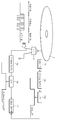
도 1은 본 발명의 양호한 실시예에 따른 근접장 광기록/재생 장치의 예시적인 구성을 개략적으로 도시하고 있다. 도 1을 참조하면, 본 발명에 따른 근접장 광기록/재생 장치(10)는, 예컨대, 광원(11), 콜리메이팅 렌즈(12), 제 1 및 제 2 빔스플리터(13, 14), 1/4 파장판(15), 대물렌즈(16), 고체함침렌즈(solid immersion lens; SIL)(17), 제 1 및 제 2 광검출기(20, 21), 연산부(22) 및 액츄에이터(23)를 포함할 수 있다.1 schematically shows an exemplary configuration of a near field optical recording / reproducing apparatus according to a preferred embodiment of the present invention. Referring to FIG. 1, the near field optical recording / reproducing
여기서, 광원(11)은 광디스크(D)에 정보를 기록하거나 또는 광디스크(D)로부터 정보를 재생하기 위한 광빔을 제공한다. 예컨대, 광원(11)으로서 405nm 파장의 청색 레이저 다이오드(laser diode; LD)를 사용할 수 있다. 또한, 콜리메이팅 렌즈(12)는 상기 광원(11)에서 방출된 광빔을 평행빔으로 바꾸는 역할을 한다.Here, the
제 1 빔스플리터(13)는 광원(11)으로부터 진행하는 광을 통과시키고, 고체함침렌즈(SIL)(17)로부터 전반사된 광을 반사하여 제 1 광검출기(20)로 진행하게 한다. 또한, 제 2 빔스플리터(14)는 광원(11)으로부터 진행하는 광을 통과시키고, 광디스크(D)로부터 반사된 광을 반사하여 제 2 광검출기(21)로 진행하게 한다. 예컨 대, 이러한 제 1 및 제 2 빔스플리터(13, 14)는 입사광의 편광방향에 따라 입사광을 투과 또는 반사하는 편광 빔스플리터일 수 있다. 1/4 파장판(15)은 입사광의 위상을 1/4 파장만큼 지연시키는 역할을 한다. 따라서, 상기 1/4 파장판(15)을 두 번 통과하게 되면 광의 편광방향이, 예컨대, s-편광에서 p-편광으로 또는 p-편광에서 s-편광으로 바뀌게 된다.The
대물렌즈(16)는 광원(11)으로부터 제공된 광을 집광하여 고체함침렌즈(17)의 표면에 스폿을 형성한다. 앞서 설명한 바와 같이, 이렇게 형성된 스폿의 일부분은 상기 고체함침렌즈(17)의 표면에서 전반사되어 상기 광원(11)을 향해 되돌아가 가며, 이 과정에서 광디스크(D)와 대향하고 있는 고체함침렌즈(17)의 표면에는 미세한 소멸파(evanescent wave)가 형성된다. 광디스크(D)와 고체함침렌즈(17) 사이의 거리가 100nm 이하인 근접장 상태에 있는 경우, 이렇게 형성된 소멸파는 상기 광디스크(D)에 전달되어 정보의 기록/재생에 사용될 수 있다.The
또한, 제 1 광검출기(20)는 상기 고체함침렌즈(17)의 표면에서 전반사된 후 제 1 빔스플리터(13)에 의해 반사되어 입사하는 갭 에러 신호(GES)의 크기를 검출하기 위한 것이다. 앞서 설명한 바와 같이, 제 1 광검출기(20)에서 검출되는 갭 에러 신호의 크기는 원격장(far-field) 상태에서 최대가 되며, 근접장(near-field) 상태에서 광디스크(D)와 고체함침렌즈(17) 사이의 거리가 작아질수록 갭 에러 신호의 크기도 작아진다.In addition, the
연산부(22)는 상기 제 1 광검출기(20)에서 검출된 갭 에러 신호(GES)의 크기와 상기 광원(11)에 제공되는 구동 신호의 크기를 받아서, 정규화된 갭 에러 신 호(normalized GES; GESn)를 제공하는 역할을 한다. 앞서 설명한 바와 같이, 제 1 광검출기(20)에서 검출되는 갭 에러 신호의 크기는 광원(11)에서 제공되는 광의 세기에 의해서도 영향을 받는다. 따라서, 연산부(22)는 광원(11)에 제공되는 구동 신호의 크기를 참조하여 상기 구동 신호의 크기에 영향을 받지 않는 정규화된 갭 에러 신호(GESn)를 계산한다. 이렇게 계산된 정규화된 갭 에러 신호(GESn)는 액츄에이터(23)로 보내져 갭 서보 동작을 수행하는 데 사용된다.The calculating
제 2 광검출기(21)는 광디스크(D)에서 반사되어 제 2 빔스플리터(14)를 통해 입사하는 광의 세기를 검출하는 역할을 한다. 공지된 바와 같이, 상기 제 2 광검출기(21)는 다수의 세그먼트로 분할된 다분할 광검출기로서, 각각의 세그먼트에서 검출된 광세기의 합은 RFSUM 신호로서 정보의 재생에 사용된다. 또한, 각각의 세그먼트에서 검출된 광세의 차이는 트래킹 에러 신호로서, 공지된 기술에 따라 트래킹 서보 동작을 수행하는 데 사용된다. 이에 대해서는 본 발명의 목적 달성과 직접적인 관계가 없고 공지된 기술이므로 상세한 설명을 생략한다.The
한편, 액츄에이터(23)는 대물렌즈(16) 및 고체함침렌즈(17)를 탑재하고 있으며, 정규화된 갭 에러 신호(GESn)와 트래킹 에러 신호로부터 갭 서보 동작 및 트래킹 서보 동작을 수행한다.On the other hand, the
도 2는 상술한 구성을 갖는 본 발명에 따른 근접장 광기록/재생 장치(10)의 동작을 개략적으로 설명하고 있다. 이하, 도 1 및 도 2를 참조하여, 본 발명에 따른 근접장 광기록/재생 장치(10)의 동작 및 갭 에러 신호(GES)의 정규화 방법에 대하여 상세하게 설명한다.2 schematically illustrates the operation of the near field optical recording / reproducing
먼저, 근접장 광기록/재생 장치(10)에 광디스크가 삽입되고 광원(11)이 ON 되면, 초기화 단계에서 디스크의 초기 틸트를 조정하고, 액츄에이터(23)를 아래 위로 이동시켜 원격장 상태에서의 갭 에러 신호(GES)의 크기(원격장 레벨) 및 광디스크(D)와 고체함침렌즈(17)가 접촉한 상태에서의 갭 에러 신호(GES)의 크기(컨택 레벨)를 확인한다. 여기까지는 일반적인 근접장 광기록/재생 장치의 초기화 단계와 동일하다.First, when the optical disk is inserted into the near field optical recording / reproducing
그런 후, 본 발명에 따르면, 액츄에이터(23)를 이용하여 고체함침렌즈(17)를 원격장의 위치로 이동시키며, 연산부(22)는 원격장 상태에서 제 1 광검출기(20)에 의해 검출된 갭 에러 신호의 크기(GES_Level)와 광원(11)에 인가되는 구동 신호의 크기(LD_Driving_Level)를 이용하여 정규화 팩터(α)를 다음과 같이 구한다.Then, according to the present invention, the
즉, 연산부(22)에서 계산된 정규화 팩터(α)는 광원(11)에 인가되는 구동 신호의 크기(LD_Driving_Level)를 원격장 상태에서 제 1 광검출기(20)에 의해 검출된 갭 에러 신호의 크기(GES_Level)로 나눈 것과 같다.That is, the normalization factor α calculated by the
이렇게 정규화 팩터(α)를 계산한 다음에는, 재생 동작을 위하여 갭 서보 및 트래킹 서보가 가능하도록 액츄에이터(23)를 근접장 위치로 풀인한다. 그런 후에는, 광원(11)에 인가되는 구동 신호의 크기(LD_Driving_Level)와 갭 에러 신호의 크기(GES_Level)를 지속적으로 측정하면서, 그 측정 값을 이용하여 연산부(22)는 다음과 같이 정규화된 갭 에러 신호(GESn)를 계산한다.After the normalization factor α is calculated in this manner, the
즉, 상기 연산부(22)에서 계산된 정규화된 갭 에러 신호(GESn)는, 재생 동작시에 측정한 갭 에러 신호의 크기(GES_Level)를 재생 동작시에 측정한 구동 신호의 크기(LD_Driving_Level)로 나누고, 여기에 먼저 얻은 정규화 팩터(α)를 곱한 것과 같다. 만약 원격장 상태에 있는 경우에는 (GES_Level)/(LD_Driving_Level)가 정규화 팩터(α)의 역수가 되므로 GESn = 1 이 된다. 그러나 근접장 상태에 있는 경우에는 GES_Level의 값이 작아지므로 GESn < 1 이 되며, 고체함침렌즈(17)가 광디스크(D)와 접촉하게 되면 GESn = 0 이 된다.That is, the normalized gap error signal GESn calculated by the calculating
그런 다음에는, 상기 연산부(22)로부터 출력된 GESn 값을 이용하여 액츄에이터(23)의 갭 서보를 제어하고, 미리 지정된 최적의 GESn 값이 유지되도록 하면서 재생을 시작한다. 예컨대, 고체함침렌즈(17)와 광디스크(D) 사이의 최적의 거리가 50nm 인 경우, 상기 연산부(22)와 액츄에이터(23)를 이용하여 GESn 값을 0.5로 유지하도록 갭 서보를 제어한다.Then, the gap servo of the
한편, 본 발명에 따른 근접장 광기록/재생 장치(10)를 기록 모드로 전환하는 경우에도 동일한 방식으로 갭 서보의 제어가 가능하다. 즉, 갭 서보 및 트래킹 서보가 가능하도록 액츄에이터(23)가 근접장 위치로 풀인된 상태에서, 광원(11)에 인가되는 구동 신호의 크기(LD_Driving_Level)와 갭 에러 신호의 크기(GES_Level)를 지속적으로 측정한다. 그리고, 연산부(22)는 구동 신호의 크기(LD_Driving_Level)와 갭 에러 신호의 크기(GES_Level)를 이용하여 상술한 수학식 2에 따라 정규화된 갭 에러 신호(GESn)를 구한다.On the other hand, even when the near-field optical recording / reproducing
앞서 설명한 바와 같이, 기록 모드에서는 광원(11)에 인가되는 구동 신호의 크기(LD_Driving_Level)가 재생 보드에서보다 약 10배 가까이 증가한다. 이때, 제 1 광검출기(20)에서 측정되는 갭 에러 신호의 크기(GES_Level)도 역시 이와 비례하여 증가한다. 따라서, 상기 구동 신호의 크기(LD_Driving_Level)와 갭 에러 신호의 크기(GES_Level)가 동일한 비율로 증가하기 때문에, 기록 모드에서도 원격장 상태에 있는 경우에는 GESn = 1 이 되며, 근접장 상태에 있는 경우에는 GESn < 1 이 되고, 고체함침렌즈(17)가 광디스크(D)와 접촉하게 되면 GESn = 0 이 된다. 그러므로, 상기 연산부(22)로부터 출력된 GESn 값을 이용하여 액츄에이터(23)의 갭 서보를 제어하고, 미리 지정된 최적의 GESn 값이 유지되도록 하면서 기록을 수행할 수 있다. 예컨대, 고체함침렌즈(17)와 광디스크(D) 사이의 최적의 거리가 50nm 인 경우, 기록 모드에서도 상기 연산부(22)와 액츄에이터(23)를 이용하여 GESn 값을 0.5로 유지하도록 갭 서보를 제어할 수 있다.As described above, in the recording mode, the magnitude LD_Driving_Level of the driving signal applied to the
이와 같이, 본 발명에 따르면, 광원(11)에 인가되는 구동 신호로 갭 에러 신호(GES)를 정규화하였기 때문에, 기록 모드와 재생 모드의 전환시에 구동 신호의 변화로 인해 갭 에러 신호의 크기가 변하더라도, 정규화된 갭 에러 신호(GESn)는 일정하게 유지될 수 있다. 따라서, 상기 정규화된 갭 에러 신호(GESn)를 이용하여 안정적으로 갭 서보를 제어할 수 있다.As described above, according to the present invention, since the gap error signal GES is normalized with the drive signal applied to the
더욱이, 본 발명에 따르면, 광원(11)에 직접 인가되는 구동 신호를 이용하여 갭 에러 신호를 정규화하기 때문에, 갭 에러 신호(GES)를 정규화하는 데 있어서 광 원(11)에서 방출되는 광의 세기 변화를 측정하기 위한 별도의 광학계 및 광검출기를 필요로 하지 않는다. 따라서, 상기 별도의 광검출기의 이득 및 오프셋 등을 조절하는 등의 부가적인 작업이 필요 없으며, 매우 정확하게 갭 에러 신호를 정규화하는 것이 가능하다.Furthermore, according to the present invention, since the gap error signal is normalized using a drive signal applied directly to the
한편, 도 3은 본 발명의 변형된 실시예에 따른 근접장 광기록/재생 장치의 구성 및 동작을 개략적으로 도시하고 있다. 도 3을 참조하면, 광원(11)과 연산부(22) 사이 및 제 1 광검출기(20)와 연산부(22) 사이에 각각 버퍼(18a,19a)와 저역통과필터(low pass filter; LPF)(18b,19b)가 더 배치되어 있다는 점에서 도 1에 도시된 실시예와 차이가 있다. 재생 모드에서는 광원(11)에서 방출되는 광의 세기가 거의 일정하게 유지되지만, 기록 모드에서는 기록하고자 하는 정보의 디지탈값에 따라 광원(11)으로부터 펄스파 형태의 광이 방출된다. 그 결과, 기록 모드에서는 구동 신호와 갭 에러 신호의 피크를 정확하게 찾기가 어렵다. 따라서, 도 3에 도시된 본 발명의 변형된 실시예에 따르면, 저역통과필터(18b,19b)를 이용하여 상기 구동 신호와 갭 에러 신호의 고주파 성분을 제거함으로써, 보다 정확한 구동 신호의 크기(LD_Driving_Level_LPF)와 갭 에러 신호의 크기(GES_Level_LPF)를 구할 수 있다. 그리고, 고주파 성분이 제거된 구동 신호의 크기(LD_Driving_Level_LPF)와 갭 에러 신호의 크기(GES_Level_LPF)를 이용하여, 보다 정확한 정규화된 갭 에러 신호(GESn)를 구할 수 있다.3 schematically shows the configuration and operation of a near field optical recording / reproducing apparatus according to a modified embodiment of the present invention. Referring to FIG. 3,
도 4는 상술한 본 발명에 따른 근접장 광기록/재생 장치(10)에서 재생시와 기록시의 구동 신호와 갭 에러 신호의 변화를 보여주고 있다. 먼저, 도 4의 (D)는 재생시와 기록시의 구동 신호를 나타내는 것으로, 재생시에는 구동 신호가 거의 일정하게 유지되고 있지만, 기록시에는 구동 신호가 펄스파의 형태를 가지며 피크의 크기도 커진다는 것을 알 수 있다. 도 4의 (E)는 저역통과필터(18b)를 통과한 후의 구동 신호를 나타낸다. 도 4의 (E)를 보면, 저역통과필터(18b)를 통과한 기록시의 구동 신호가 일정하게 유지되고 있음을 알 수 있다.Fig. 4 shows the change of the drive signal and the gap error signal during reproduction and during recording in the near field optical recording / reproducing
또한, 도 4의 (B)는 재생시와 기록시의 갭 에러 신호를 나타내는 것으로, 재생시에는 갭 에러 신호가 거의 일정하게 유지되고 있지만, 기록시에는 갭 에러 신호도 역시 펄스파의 형태를 갖는다. 또한, 기록시에는 구동 신호의 크기가 커짐에 따라 갭 에러 신호의 크기도 역시 커진다는 것을 알 수 있다. 따라서, 정규화되지 않은 경우 재생시와 기록시의 신호 편차로 인하여, 갭 에러 신호만으로는 기록시에 정확한 갭 서보 제어가 곤란하게 된다. 도 4의 (C)는 저역통과필터(19b)를 통과한 후의 갭 에러 신호로서, 저역통과필터(19b)를 통과한 기록시의 갭 에러 신호가 일정하게 유지되고 있음을 알 수 있다. 마지막으로, 도 4의 (A)는 본 발명에 따라 정규화된 갭 에러 신호를 나타내고 있다. 도 4의 (A)를 통해 알 수 있듯이, 본 발명에 따라 정규호된 갭 에러 신호는 재생시와 기록시에 모두 일정한 값을 유지할 수 있다. 따라서, 상기 정규화된 갭 에러 신호를 이용하면, 재생시와 기록시에 모두 정확한 갭 서보 제어가 가능하다.4B shows a gap error signal during reproduction and recording. The gap error signal is kept substantially constant during reproduction, but the gap error signal also has the form of a pulse wave during recording. In addition, it can be seen that the size of the gap error signal also increases as the size of the drive signal increases during recording. Therefore, if it is not normalized, due to signal deviation at the time of reproduction and recording, accurate gap servo control at the time of recording is difficult with only the gap error signal. 4 (C) shows a gap error signal after passing through the
지금까지, 본원 발명의 이해를 돕기 위하여 모범적인 실시예가 설명되고 첨부된 도면에 도시되었다. 그러나, 이러한 실시예는 단지 본 발명을 예시하기 위한 것이고 이를 제한하지 않는다는 점이 이해되어야 할 것이다. 그리고 본 발명은 도 시되고 설명된 설명에 국한되지 않는다는 점이 이해되어야 할 것이다. 이는 다양한 다른 변형이 본 기술분야에서 통상의 지식을 가진 자에게 일어날 수 있기 때문이다.To date, exemplary embodiments have been described and illustrated in the accompanying drawings in order to facilitate understanding of the present invention. However, it should be understood that such embodiments are merely illustrative of the invention and do not limit it. And it is to be understood that the invention is not limited to the illustrated and described description. This is because various other modifications may occur to those skilled in the art.
도 1은 본 발명의 예시적인 실시예에 따른 근접장 광기록/재생 장치의 구성을 개략적으로 도시하는 구성도이다.1 is a configuration diagram schematically showing a configuration of a near field optical recording / reproducing apparatus according to an exemplary embodiment of the present invention.
도 2는 본 발명의 예시적인 실시에에 따른 근접장 광기록/재생 장치의 동작 순서를 개략적으로 설명하는 흐름도이다.Fig. 2 is a flowchart schematically illustrating the operation sequence of the near field optical recording / reproducing apparatus according to the exemplary embodiment of the present invention.
도 3은 본 발명의 변형된 실시예에 따른 근접장 광기록/재생 장치의 구성 및 동작을 개략적으로 도시한다.3 schematically shows the configuration and operation of a near field optical recording / reproducing apparatus according to a modified embodiment of the present invention.
도 4는 본 발명의 예시적인 실시예에 따른 근접장 광기록/재생 장치에서 재생시와 기록시의 구동 신호와 갭 에러 신호의 변화를 보여준다.Fig. 4 shows changes in drive signals and gap error signals during playback and during recording in a near field optical recording / reproducing apparatus according to an exemplary embodiment of the present invention.
< 도면의 주요 부분에 대한 부호의 설명 ><Description of Symbols for Main Parts of Drawings>
10.....근접장 광기록/재생 장치 11.....광원10 ..... Near-field optical recording / reproducing
12.....콜리메이팅 렌즈 13.....제 1 빔스플리터12 .....
14.....제 2 빔스플리터 15.....1/4 파장판14 .....
16.....대물렌즈 17.....고체함침렌즈16..
18a,19a.....버퍼 18b,19b.....저역통과필터18a, 19a .....
20.....갭 에러 신호 검출부 21.....RF 신호 검출부20 ..... Gap
22.....정규화된 갭 에러 신호 연산부 23.....액츄에이터22 ..... Normalized gap
Claims (9)
Priority Applications (3)
| Application Number | Priority Date | Filing Date | Title |
|---|---|---|---|
| KR1020080002929A KR20090077145A (en) | 2008-01-10 | 2008-01-10 | Near-field optical recording / reproducing apparatus and gap error signal normalization method of the apparatus |
| PCT/KR2008/002877 WO2009088127A1 (en) | 2008-01-10 | 2008-05-23 | Near field optical recording/reproducing apparatus and method of normalizing gap error signal of the same |
| US12/128,006 US7916586B2 (en) | 2008-01-10 | 2008-05-28 | Near field optical recording/reproducing apparatus and method of normalizing gap error signal of the same |
Applications Claiming Priority (1)
| Application Number | Priority Date | Filing Date | Title |
|---|---|---|---|
| KR1020080002929A KR20090077145A (en) | 2008-01-10 | 2008-01-10 | Near-field optical recording / reproducing apparatus and gap error signal normalization method of the apparatus |
Publications (1)
| Publication Number | Publication Date |
|---|---|
| KR20090077145A true KR20090077145A (en) | 2009-07-15 |
Family
ID=40850512
Family Applications (1)
| Application Number | Title | Priority Date | Filing Date |
|---|---|---|---|
| KR1020080002929A Withdrawn KR20090077145A (en) | 2008-01-10 | 2008-01-10 | Near-field optical recording / reproducing apparatus and gap error signal normalization method of the apparatus |
Country Status (3)
| Country | Link |
|---|---|
| US (1) | US7916586B2 (en) |
| KR (1) | KR20090077145A (en) |
| WO (1) | WO2009088127A1 (en) |
Cited By (1)
| Publication number | Priority date | Publication date | Assignee | Title |
|---|---|---|---|---|
| CN113509570A (en) * | 2021-05-17 | 2021-10-19 | 四川大学 | Feeding bottle degassing unit based on low temperature plasma |
Families Citing this family (4)
| Publication number | Priority date | Publication date | Assignee | Title |
|---|---|---|---|---|
| JP2009158007A (en) * | 2007-12-26 | 2009-07-16 | Sony Corp | Optical pickup device, optical recording / reproducing device, and gap control method |
| EP2299444A1 (en) * | 2009-09-15 | 2011-03-23 | Thomson Licensing | Near-field optical recording apparatus, method and medium |
| CN102237100A (en) * | 2010-04-23 | 2011-11-09 | 建兴电子科技股份有限公司 | Lens push-in method in near field optical access system |
| US8854939B2 (en) * | 2011-03-22 | 2014-10-07 | Panasonic Corporation | Optical information apparatus and gap control method thereof |
Family Cites Families (8)
| Publication number | Priority date | Publication date | Assignee | Title |
|---|---|---|---|---|
| JP3478969B2 (en) * | 1998-03-12 | 2003-12-15 | パイオニア株式会社 | Light head |
| JP4250794B2 (en) * | 1998-10-28 | 2009-04-08 | ソニー株式会社 | Distance change detection method and apparatus, focus control method and apparatus, and total reflected light detection method |
| JP2001023190A (en) * | 1999-07-07 | 2001-01-26 | Sony Corp | Exposure apparatus, exposure method, optical disk apparatus, and recording and / or reproducing method |
| KR20030056573A (en) * | 2001-12-28 | 2003-07-04 | 한국전자통신연구원 | Measurement apparatus for detecting slant angle of solid immersion lens |
| US7791986B2 (en) * | 2006-03-15 | 2010-09-07 | Canon Kabushiki Kaisha | Optical information recording/reproducing apparatus |
| WO2007114567A1 (en) * | 2006-04-04 | 2007-10-11 | Lg Electronics Inc. | Data recording/reproducing method and apparatus |
| JP2007323791A (en) * | 2006-06-05 | 2007-12-13 | Canon Inc | Optical information recording / reproducing apparatus |
| JP2008041219A (en) * | 2006-08-09 | 2008-02-21 | Sony Corp | Optical disc apparatus and servo control method |
-
2008
- 2008-01-10 KR KR1020080002929A patent/KR20090077145A/en not_active Withdrawn
- 2008-05-23 WO PCT/KR2008/002877 patent/WO2009088127A1/en not_active Ceased
- 2008-05-28 US US12/128,006 patent/US7916586B2/en not_active Expired - Fee Related
Cited By (2)
| Publication number | Priority date | Publication date | Assignee | Title |
|---|---|---|---|---|
| CN113509570A (en) * | 2021-05-17 | 2021-10-19 | 四川大学 | Feeding bottle degassing unit based on low temperature plasma |
| CN113509570B (en) * | 2021-05-17 | 2022-05-31 | 四川大学 | Feeding bottle degassing unit based on low temperature plasma |
Also Published As
| Publication number | Publication date |
|---|---|
| US20090180372A1 (en) | 2009-07-16 |
| US7916586B2 (en) | 2011-03-29 |
| WO2009088127A1 (en) | 2009-07-16 |
Similar Documents
| Publication | Publication Date | Title |
|---|---|---|
| JP5452040B2 (en) | Optical information reproducing method, optical head, and optical disc apparatus | |
| JP3956547B2 (en) | Optical recording apparatus, optical recording and / or reproducing method | |
| KR20090077145A (en) | Near-field optical recording / reproducing apparatus and gap error signal normalization method of the apparatus | |
| US7764576B2 (en) | Optical information recording and reproducing apparatus | |
| JP2016027523A (en) | Optical recording and reproducing device | |
| JP2009508287A (en) | Apparatus and method for recording data on recording medium, and apparatus and method for reproducing data from recording medium | |
| KR20090083065A (en) | Near Field Optical Recording / Playback Device and Tilt Control Method | |
| US7920449B2 (en) | Method of controlling focus of optical information storage media recording and/or reproduction apparatus and apparatus therefor | |
| US20070280065A1 (en) | Optical information recording/reproduction apparatus | |
| JP2004335064A (en) | Information recording apparatus and method, information reproducing apparatus and method | |
| US8526287B2 (en) | Optical disk apparatus | |
| US7355953B2 (en) | Optical pickup for cutting off optical noise and optical recording and/or reproducing apparatus using the same | |
| JP3821473B2 (en) | Optical pickup device and optical disk device | |
| JP2009537057A (en) | Recording / reproducing apparatus and tracking control method | |
| KR101350988B1 (en) | Method and apparatus for generating tracking error signal and optical information storage system employing the same | |
| JP2628972B2 (en) | Optical recording device | |
| US20120263025A1 (en) | Optical disc device | |
| US20110002117A1 (en) | Optical disc drive | |
| JP2005038472A (en) | Optical recording medium recording / reproducing apparatus having spherical aberration compensation mechanism and spherical aberration compensation method | |
| JP4956325B2 (en) | Optical pickup | |
| CN101996647B (en) | Optical disc apparatus and optical disc reproducing method | |
| CN101276610B (en) | Tracking control method for read/write optical disc | |
| JP2004014047A (en) | Optical disc device and aberration compensation method in optical disc device | |
| JP2011003232A (en) | Optical disk device | |
| JP2012174292A (en) | Optical disk device |
Legal Events
| Date | Code | Title | Description |
|---|---|---|---|
| PA0109 | Patent application |
Patent event code: PA01091R01D Comment text: Patent Application Patent event date: 20080110 |
|
| PG1501 | Laying open of application | ||
| PC1203 | Withdrawal of no request for examination | ||
| WITN | Application deemed withdrawn, e.g. because no request for examination was filed or no examination fee was paid |