KR20100104792A - Dust separating apparatus having attachable centrifugal separator and dust box - Google Patents
Dust separating apparatus having attachable centrifugal separator and dust box Download PDFInfo
- Publication number
- KR20100104792A KR20100104792A KR1020090023431A KR20090023431A KR20100104792A KR 20100104792 A KR20100104792 A KR 20100104792A KR 1020090023431 A KR1020090023431 A KR 1020090023431A KR 20090023431 A KR20090023431 A KR 20090023431A KR 20100104792 A KR20100104792 A KR 20100104792A
- Authority
- KR
- South Korea
- Prior art keywords
- dust
- centrifuge
- dust container
- container
- vacuum cleaner
- Prior art date
- Legal status (The legal status is an assumption and is not a legal conclusion. Google has not performed a legal analysis and makes no representation as to the accuracy of the status listed.)
- Ceased
Links
Images


Classifications
-
- A—HUMAN NECESSITIES
- A47—FURNITURE; DOMESTIC ARTICLES OR APPLIANCES; COFFEE MILLS; SPICE MILLS; SUCTION CLEANERS IN GENERAL
- A47L—DOMESTIC WASHING OR CLEANING; SUCTION CLEANERS IN GENERAL
- A47L9/00—Details or accessories of suction cleaners, e.g. mechanical means for controlling the suction or for effecting pulsating action; Storing devices specially adapted to suction cleaners or parts thereof; Carrying-vehicles specially adapted for suction cleaners
- A47L9/10—Filters; Dust separators; Dust removal; Automatic exchange of filters
- A47L9/16—Arrangement or disposition of cyclones or other devices with centrifugal action
Landscapes
- Engineering & Computer Science (AREA)
- Mechanical Engineering (AREA)
- Filters For Electric Vacuum Cleaners (AREA)
- Centrifugal Separators (AREA)
Abstract
본원 발명은 원심분리형 진공청소기에서 원심분리기와 먼지통이 분리 가능하게 구성된 분리형 원심분리기와 먼지통을 구비한 진공청소기의 집진장치로서, 일 측에 유입공이 형성되고 타 측에 먼지배출구가 형성된 원심분리기와; 상기 먼지배출구로부터 분리되는 먼지를 수용하는 먼지통;을 포함하며, 상기 원심분리기가 상기 먼지통의 개방된 상면을 통해 상기 먼지통의 내부에 장착 및 분리가능하도록 구성되어, 진공청소기의 오물 수집 효율을 현저히 향상시키고, 청소 및 수리를 용이하게 하는 것에 의해 진공청소기의 수명을 연장시키는 효과를 제공한다.The present invention is a centrifugal vacuum cleaner comprising a centrifugal separator and a dust container configured to be separated from the dust container, the dust collecting device of the vacuum cleaner, comprising: a centrifuge having an inlet formed on one side and a dust outlet formed on the other side; And a dust container accommodating dust separated from the dust discharge port, wherein the centrifugal separator is configured to be mounted and detached into the dust container through an open upper surface of the dust container, thereby significantly improving dust collection efficiency of the vacuum cleaner. And the life of the vacuum cleaner is extended by facilitating cleaning and repair.
Description
본원 발명은 원심분리형 진공청소기에서 원심분리기와 먼지통이 분리가능하게 구성되는 분리형 원심분리기와 먼지통을 구비한 진공청소기의 집진장치에 관한 것이다.The present invention relates to a dust collecting device of a vacuum cleaner having a separate type centrifuge and a dust container in which the centrifuge and the dust container are separable in the centrifugal vacuum cleaner.
일반적으로, 싸이클론(Cyclone) 청소기라고 알려진 원심분리형 진공청소기의 집진장치는 흡입된 공기로부터 먼지, 물 등의 오물을 원심력을 이용하여 분리하는 원심분리기와 분리된 오물을 수집하는 먼지통을 포함하여 구성된다.In general, the dust collector of the centrifugal vacuum cleaner known as a cyclone cleaner includes a centrifuge for separating dust, water, and the like from the sucked air by centrifugal force, and a dust bin for collecting the separated dirt. do.
상술한 원심분리형 진공청소기의 일 예로는 원심분리기의 효율을 향상시키기 위하여 먼지통의 내부 공간을 1차분리방과 2차분리방으로 분할하고, 원심분리기를 고정장착하여 흡입된 공기가 먼지통으로 유입되는 경우, 1차분리방에서 먼지, 물 등의 오물이 관성에 의해 먼저 분리되어 수집된 후 원심분리기로 유입되어서 원심분리에 의해 다시 미세먼지가 분리되어 2차분리방에 수집되는 구조를 가지는 등록특허 10-759918의 "수분 및 먼지가 다단 분리되는 진공청소기" 등을 들 수 있다.As an example of the above-described centrifugal vacuum cleaner, in order to improve the efficiency of the centrifuge, the internal space of the dust container is divided into a primary separation room and a secondary separation room, and the suctioned air is introduced into the dust container by fixedly mounting a centrifuge. , Dust, water, etc. in the primary separation room is first separated and collected by inertia, flowed into the centrifuge, fine dust is separated again by centrifugation and collected in the secondary separation room. "Vacuum cleaner in which water and dust are separated in multiple stages" of -759918.
그러나 상술한 등록특허와 같은 구조를 가지는 종래기술의 진공청소기의 경 우에는 원심분리기 내부의 청소, 먼지통에서의 오물의 배출이 용이하지 않으며, 원심분리기 내로 수분이 유입되는 것에 의해 청소기의 고장 또는 성능 열화를 발생시킬 수 우려가 있다.However, in the case of the vacuum cleaner of the prior art having the same structure as the above-described patent, it is not easy to clean the inside of the centrifuge and to discharge the dirt from the dust container, and the malfunction or performance of the vacuum cleaner due to the inflow of moisture into the centrifuge There is a risk of deterioration.
본원 발명은 상술한 종래기술의 문제점을 해소하기 위한 것으로서, 원심분리기와 먼지통의 제작을 용이하게 하고, 사용 중에는 수리, 청소 등의 보수 작업을 용이하게 수행할 수 있도록 하는 분리형 원심분리기와 먼지통을 구비한 진공청소기의 집진장치를 제공하는 것을 그 목적으로 한다. The present invention is to solve the problems of the prior art described above, it is easy to manufacture the centrifuge and the dust container, and provided with a separate centrifuge and the dust container to facilitate the maintenance work such as repair, cleaning, etc. during use It is an object to provide a dust collector of a vacuum cleaner.
또한, 본 발명의 다른 목적은 포집된 수분이 원심분리기로 유입되는 것을 효과적으로 차단하는 분리형 원심분리기와 먼지통을 구비한 진공청소기의 집진장치를 제공하는 것을 그 목적으로 한다.Another object of the present invention is to provide a dust collector of a vacuum cleaner having a separate type centrifuge and a dust container that effectively blocks the collected water from flowing into the centrifuge.
또한, 본 발명의 또 다른 목적은 구조가 개선된 분리형 원심분리기와 먼지통을 구비한 진공청소기의 집진장치를 제공하는 것을 그 목적으로 한다.Another object of the present invention is to provide a dust collector of a vacuum cleaner having a separate type centrifuge and a dust container having an improved structure.
상술한 목적을 달성하기 위한 본원 발명의 집진장치는, 일 측에 유입공이 형성되고 타 측에 먼지배출구가 형성된 원심분리관을 포함한 원심분리기와; 상기 먼지배출구로부터 분리되는 먼지를 수용하는 먼지통;을 포함하며, 상기 원심분리기가 상기 먼지통의 개방된 상면을 통해 상기 먼지통의 내부로 장착 및 분리가능하도록 구성된다.The dust collector of the present invention for achieving the above object, the centrifuge comprising a centrifuge tube formed with an inlet hole on one side and a dust outlet on the other side; And a dust container accommodating dust separated from the dust discharge port, wherein the centrifuge is configured to be mounted and detached into the dust container through an open upper surface of the dust container.
상기 원심분리기의 유입공은 공기의 회전 운동을 위해 헬리컬(helical) 또는 경사형(tangential)의 형상으로 구성된다. 상기 원심분리기는 또한 먼지 배출의 효율 향상을 위해 유입된 공기의 회전 중심이 상기 먼지통의 중심 축에 대하여 경사 지도록 구성될 수 있다. The inlet hole of the centrifuge has a helical or tangential shape for rotational movement of air. The centrifuge may also be configured such that the rotational center of the introduced air is inclined with respect to the central axis of the dust container to improve the efficiency of dust discharge.
그리고 원심분리기의 유입공 또는 먼지배출구에는 먼지통 내부에 물이 차는 경우 물이 원심분리기 내부로 유입되는 것을 차단하기 위해 부력에 의해 유입공 또는 먼지배출구를 막는 차단부재가 구비될 수 있다. In addition, the inlet hole or the dust outlet of the centrifuge may be provided with a blocking member for blocking the inlet hole or the dust outlet by buoyancy to block water from flowing into the centrifuge when the water is filled in the dust container.
또한, 상기 원심분리기의 상부에는 필터 조립체가 장착 및 분리 가능하게 설치될 수 있다.In addition, the filter assembly may be mounted on the top of the centrifuge so as to be mounted and detached.
또한, 상기 원심 분리기는 상기 유입공을 형성하는 유입관을 구비하고, 상기 먼지통은 상기 유입관과 결합되는 흡입관을 포함할 수 있다.In addition, the centrifugal separator may include an inlet pipe forming the inlet hole, and the dust container may include a suction pipe coupled with the inlet pipe.
본원 발명의 목적은, 일 측에 유입공이 형성되고 타 측에 먼지배출구가 형성된 원심분리기와; 분리벽에 의해 관성먼지통과 원심먼지통으로 분리된 먼지 수집영역을 구비하여 상기 유입공으로 유입되는 공기와 상기 먼지배출구로부터 분리되는 먼지를 분리 수집하는 먼지통;을 포함하고, 상기 원심분리기는 상기 먼지통의 개방된 상면을 통해 먼지통의 내부에 장착 및 분리 가능하게 구성된 집진장치에 의해서도 달성된다.An object of the present invention, the inlet hole is formed on one side and the dust discharge port formed on the other side; And a dust container having a dust collection area separated by an inertial dust container and a centrifugal dust container by separating walls to separate and collect the air flowing into the inflow hole and the dust separated from the dust discharge port, wherein the centrifugal separator opens the dust container. It is also achieved by a dust collector configured to be mounted and detached inside the dust container through the top surface.
상기 원심분리기는, 유입공이 관성먼지통의 위치에 형성되고, 먼지배출구가 원심먼지통의 위치되도록 형성될 수 있다.The centrifuge, the inlet hole may be formed in the position of the inertial dust container, the dust outlet may be formed so that the position of the centrifugal dust container.
상기 먼지통 내부의 분리벽은 상부에 원심분리기의 저면 형상으로 요입형성되는 안착부가 형성되는 것에 의해 원심분리기가 먼지통의 내측에서 분리벽과 긴밀히 밀착되도록 한다.The partition wall inside the dust container has a seating portion formed in the bottom shape of the centrifuge at the top thereof so that the centrifuge is in close contact with the separation wall inside the dust container.
이때 원심분리기의 저면에는 분리벽의 상부모서리가 삽입 결합되는 홈을 가 지는 가스켓이 형성되어, 먼지통의 내측에 장착되어 고정되는 것을 견고히 하고, 먼지통 내측에 형성되는 관성먼지통과 원심먼지통 사이를 효율적으로 격리시키도록 구성될 수 있다.At this time, the bottom surface of the centrifuge is formed with a gasket having a groove into which the upper edge of the separation wall is inserted, and firmly mounted and fixed to the inside of the dust container, and efficiently between the inertial dust container and the centrifugal dust container formed inside the dust container. Can be configured to isolate.
또한, 상기 원심분리기는 유입공의 입구 측에 결합되어 부력에 의해 상기 유입공의 입구를 차폐하는 차단부재가 더 구비됨으로써 먼지통에 물이 차는 경우 물이 원심분리기의 내측으로 유입되는 것을 방지하도록 구성될 수 있다.In addition, the centrifuge is coupled to the inlet side of the inlet hole is further provided with a blocking member for shielding the inlet of the inlet hole by buoyancy to prevent water from entering the inside of the centrifuge when the water filled in the dust container Can be.
본원 발명의 집진장치는 집진효율을 향상시키기 위하여 병렬로 배치된 2개 이상의 원심분리관을 구비할 수 있다.The dust collector of the present invention may be provided with two or more centrifuge tubes arranged in parallel to improve the dust collection efficiency.
상술한 목적을 달성하기 위한 본원 발명의 또 다른 집진장치는, 수직원심분리기와; 상기 수직원심분리기의 하측에 결합되는 원심먼지통과; 상기 수직원심분리기와 상기 원심먼지통을 포함하는 관성먼지통;으로 구성될 수 있다.Another dust collector of the present invention for achieving the above object is a vertical centrifuge; A centrifugal dust passage coupled to the lower side of the vertical centrifuge; It may be composed of; an inertial dust container including the vertical centrifuge and the centrifugal dust container.
또한, 본 발명의 집진장치는, 내측에 안정기와 그릴이 서로 대향하도록 돌출 형성되는 누운 관형의 원심분리관과; 상기 그릴과 연통되도록 상기 원심분리관에 형성되는 배기관과; 상기 배기관의 상부 구멍에 결합되는 상부커버와; 상기 원심분리기와 상기 배기관을 수용하는 먼지통을 포함하고, 상기 먼지통은 내측면의 위치에 외부의 공기가 유입되도록 외부 호스가 연결되는 흡기공이 형성되고, 상기 흡기공의 내측으로 먼지통의 내측면에서 수평방향으로 원주를 따라 부착되는 흡기관을 구비할 수 있다. 이때 상기 흡기관은 외부로부터 유입된 공기가 먼지통의 수평단면의 원주 방향을 따라 회전되도록 형성될 수 있다.In addition, the dust collector of the present invention, and the inner tubular centrifuge tube protruding to be formed so that the ballast and the grill to face each other; An exhaust pipe formed in the centrifuge tube so as to communicate with the grill; An upper cover coupled to an upper hole of the exhaust pipe; And a dust container for accommodating the centrifuge and the exhaust pipe, wherein the dust container has an intake hole to which an external hose is connected so that external air flows into a position of an inner surface thereof, and is horizontal on an inner surface of the dust container to the inside of the intake hole. And an intake pipe attached along the circumference in the direction. At this time, the intake pipe may be formed so that the air introduced from the outside is rotated along the circumferential direction of the horizontal cross section of the dust container.
또한, 상술한 본 발명의 구성에서 원심분리관은 그릴이 형성된 면과 대향하 는 면이 개방부로 형성되고, 개방부와 대향하는 먼지통의 내면에는 개방부를 통해 원심분리관과 결합하는 안정기가 설치되도록 구성할 수 있다.In addition, in the above-described configuration of the present invention, the centrifuge tube is formed with an open side facing the surface on which the grill is formed, and the ballast coupled to the centrifuge tube through the opening is installed on the inner surface of the dust container facing the opening. Can be configured.
본원 발명의 분리형 원심분리기와 먼지통을 구비한 진공청소기용 집진장치는 원심분리기와 먼지통을 개별적으로 제작하여 결합할 수 있도록 함으로써 일체형으로 구성되는 경우에서와 같이 원심분리기와 먼지통을 결합시키는 별도의 공정을 필요로 하지 않음으로써 제작을 용이하게 하고 제작비용을 절감시키는 효과를 제공한다.The dust collector for a vacuum cleaner having a separate centrifuge and a dust container of the present invention allows a separate process of combining the centrifuge and the dust container as in the case of an integral type by allowing the centrifuge and the dust container to be individually manufactured and combined. By not requiring it, it facilitates the production and provides the effect of reducing the production cost.
또한, 원심분리기와 먼지통을 착탈 가능하게 구성한 것에 의해 오물의 배출과, 원심분리기와 먼지통의 청소를 용이하게 하며, 원심분리기와 먼지통이 분리되는 것에 의해 원심분리기와 먼지통의 수리 및 보수를 용이하게 수행할 수 있도록 한다.In addition, the centrifuge and the dust container are detachably configured to facilitate the discharge of dirt, the cleaning of the centrifuge and the dust container, and the centrifuge and the dust container separated so that the centrifuge and the dust container can be easily repaired and repaired. Do it.
또한, 본원 발명의 집진장치는 원심분리기의 먼지배출구 또는 원심분리관의 유입공에 부력에 의해 유입공을 차폐하는 차단부재를 구비함으로써 원심분리관의 내측으로 물이 유입되는 것을 방지하여 물이 유입에 의해 모터가 고장 나는 등에 의한 진공청소기의 성능 열화를 방지하고, 이로 인해 진공청소기의 수명을 현저히 연장시킬 수 있도록 하는 효과를 제공한다.In addition, the dust collector of the present invention is provided with a blocking member for shielding the inlet hole by buoyancy in the dust outlet of the centrifuge or the inlet hole of the centrifugal separator to prevent water from flowing into the inside of the centrifuge tube to prevent the inflow of water. This prevents the deterioration of the vacuum cleaner's performance due to a motor failure and the like, thereby providing an effect of significantly extending the life of the vacuum cleaner.
또한, 본원 발명의 집진장치는 원심분리관의 안정기를 원심분리관과 분리하여 먼지통의 내측면에 구비함으로써, 원심분리기를 먼지통으로부터 쉽게 분리 및 장착 할 수 있고, 사용자가 원심분리관의 내측을 보다 용이하게 확인할 수 있을 뿐 아니라 원심 분리관의 청소 및 보수 유지를 편리하게 수행할 수 있도록 한다.In addition, the dust collector of the present invention separates the ballast of the centrifuge tube from the centrifuge tube and is provided on the inner side of the dust container, so that the centrifuge can be easily separated and mounted from the dust container, and the user can see the inside of the centrifuge tube. Not only can it be easily confirmed, but also the cleaning and maintenance of the centrifuge tube can be performed conveniently.
이하, 첨부 도면을 참조하여 본원 발명을 더욱 상세히 설명한다.Hereinafter, the present invention will be described in more detail with reference to the accompanying drawings.
도 1 내지 도 3은 본 발명의 제 1 실시 예에 따른 집진장치(50)로서, 도 1은 분리 사시도, 도 2는 수직단면도이고, 도 3은 도 2의 Ⅱ-Ⅱ의 우측방향에서 바라본 유입공(61')을 구비한 유입관(61)과 흡입공(52')을 구비한 흡입관(52)의 결합상태를 나타내는 단면도이다.1 to 3 are
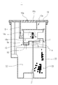
도 1 내지 도 3에 도시된 바와 같이 본원 발명의 제 1 실시 예에 따르는 집진장치(50)는, 먼지통(51)과; 먼지통(51)의 개방된 상면을 통해 먼지통(51)의 내부에 장착 또는 분리되는 원심분리기(60)로 구성된다.1 to 3, the
원심분리기(60)는 외부공기가 원심분리기(60)의 내측으로 유입되도록 먼지통(51)에 형성된 흡입관(52)과 결합되는 유입관(61)과, 유입된 공기의 회전에 의해 분리된 먼지를 먼지통으로 배출하는 먼지배출구(62)가 형성된다. 유입관(61)은 입구의 저부가 입구의 상부보다 원심분리기(60)로부터의 길이가 짧은 경사 단면을 가진다.The centrifuge (60) is an inlet pipe (61) coupled with the suction pipe (52) formed in the dust container (51) so that external air flows into the centrifuge (60), and the dust separated by the rotation of the introduced air. The
원심분리기(60)의 내부 공간에는 그릴(64)이 형성되고 그릴(64)에 대향되는 면은 개방된 개방부(60a)가 형성된다. 상부에는 원심분리기(60)의 내부공간과 연통되며 상부에 배기구가 형성된 배기관(65)이 설치된다. 배기관(65)의 단면은 상방향으로 확대되는 형상이고, 배기관(65)의 상단에는 필터조립체(18b)가 분리 가능하게 장착된다.The
필터 조립체(18b)는 필터 케이스(18b-1)와 마이크로 필터(18b-2) 및 스폰지 필터(18b-3)로 구성되어 있다. 먼지를 버리기 위해 먼지통(51)을 청소기 본체(미도시)로부터 분리하거나, 먼지통(51)으로부터 필터 조립체(18b) 및 원심분리기(60)를 장착 및 분리하는 것을 용이하게 할 수 있도록 원심분리기(51)의 상단에는 손잡이(미 도시)가 설치될 수 있다.The
상기 먼지통(51)의 일 측에는 흡입공(52')이 형성되어 있으며, 내면에 안정기(63)가 설치되어 있으며, 상부는 개방되는 구조를 가진다. 흡입공(52')은 원심분리기(60)의 유입공(61')과 대응되는 위치에 형성되고, 도 2에 도시된 바와 같이 외측으로 외부 호스(H)가 연결된다. 또한, 흡입공(52')에는 먼지통(51) 내부로 돌출된 흡입관(52)이 구비된다. 흡입관(52)은 흡입관(52)의 상부가 하부보다 먼지통(51)으로부터 돌출된 길이가 길도록 경사진 단면을 가지도록 형성되어 원심분리기(60)가 먼지통(51)의 개방된 상부를 통해 먼지통(51)의 내부로 장착되는 경우 흡입관(52)이 원심 분리기의 유입관(61)과 밀착 결합된다. 먼지통(51)의 일 측면에는 내부를 관측할 수 있는 투명한 관측부(도면에 미 도시)가 형성될 수 있다.The suction hole 52 'is formed at one side of the
제 1 실시 예의 집진장치(50)는, 먼지통(51)의 개방된 상면을 통해 원심분리기(60)가 먼지통(51)의 내부로 삽입되고, 원심분리기(60)의 배기관(65)의 외주연이 먼지통(51)의 개방된 상부 입구부의 원주연과 억지끼움 등의 방식으로 결합되어 먼지통(51)에 장착된다. 이때 원심분리기(60)의 개방부(60a)는 먼지통(51)의 안정기(63)와 결합되고, 유입관(61)은 단면이 흡입관(52) 입구 부 단면을 따라 미끄러지면서 흡입관(52)과 결합된다. 따라서, 원심분리기(60)가 먼지통(51)의 내부로 삽 입되는 동작이 흡입관(52)에 의해 방해되지 않으면서 유입관(61)과 흡입관(52)의 확실한 밀폐 결합이 이루어진다. 또한 분리시에는 원심분리기(60)의 상부 손잡이(미 도시)를 잡아서 상부로 인출하면 억지끼움 결합이 해제되어 먼지통(51)의 개방된 상부를 통해 원심분리기(60)가 외부로 인출된다. 설명되지 않은 도 1 및 도 2의 참조부호 66은 먼지통 및 배기관 상부 개구를 덮는 상부커버이고, 도 3의 a는 외부 호스(H)의 출구를 나타낸다.In the
도 4 내지 도 8은 본원 발명의 제 2 실시 예에 따른 집진장치(1)를 도시한 것으로서, 도 4는 단면도이고, 도 5는 차단부재로서의 차단커버(15)의 구성을 나타내는 측면도이며, 도 6은 도 4의 집진장치 중 먼지통(20)의 내부 사시도이고, 도 7은 먼지통(20)에 원심분리기(10)가 장착된 상태의 집진장치(1)의 단면 사시도이며, 도 8은 제 2 실시 예에 따른 집진장치(1)의 집진과정을 나타내는 도면이다.4 to 8 show a
본원 발명의 제 2 실시 예에 따른 집진장치(1)는 먼지통(20)의 상부에 착탈 가능하게 결합되는 원심분리기(10a)와 관성먼지통(22)과 원심먼지통(23)의 2개의 집진영역을 가지는 먼지통(20)으로 구성된다.The
상기 원심분리기(10a)는, 유입된 공기를 회전시켜 먼지를 분리하는 원심분리관(11)과; 먼지가 분리된 공기가 원심분리기(10)의 외부로 배출되는 배기관(18)과; 관성먼지통(22)의 내부에 물(27)이 차는 경우 원심분리관(11)의 내부로 물이 유입되는 것을 차단하는 차단커버(15);로 구성된다. 참조부호 19는 배기관(18) 상단에 결합되며 배기공(19a)이 형성된 상부커버이다.The centrifuge (10a), the centrifuge tube (11) for separating the dust by rotating the introduced air; An
상기 원심분리관(11)은 누운 관형상으로 내부 공간의 측면을 이루는 관 양측에서 서로 대향 되도록 돌출 형성된 안정기(stabilizer)(12)와 그릴(13)이 구비된다. 원심분리관(11)의 일 측면 중 관성먼지통(22)에 위치되는 면에는 먼지를 포함하는 공기가 유입되는 유입관(14)이 형성된다. 상기 안정기(stabilizer)(12)는 제 1 실시 예에서와 같이 원심분리관(11)과 분리되어 원심먼지통(23)의 내측벽에 설치되고, 상기 원심분리관(11)의 그릴(13)에 대향하는 면이 개방부(60a)를 가지도록 구성될 수도 있다(도 1 참조).The centrifuge tube (11) is provided with a stabilizer (12) and a grill (13) protruding to face each other on both sides of the tube forming a side of the inner space in a lying tube shape. One side of the
또한, 원심분리관(11)의 일 측면 중 원심먼지통(23)에 위치되는 면에는 원심분리된 미세먼지(26)가 원심먼지통(23)으로 배출되는 먼지배출구(17)가 형성된다. 이러한 구성을 가지는 원심분리관(11)은 원통형으로 형성되는 것이 바람직하나, 본 발명의 원심분리관(11)의 형상은 실시자의 필요에 따라 다양한 형태를 가질 수 있다.In addition, the surface of the
상기 배기관(18)은 그릴(13)의 내측 중공과 연통되는 배기유로(18a)를 이루도록 관 형상으로 원심분리관(11)의 상측에 형성되어 원심분리관(11)의 내부 공기를 배출하도록 형성된다.The
배기관(18)의 배기구가 위치되는 개방된 상부에는 필터조립체(18b)를 고정시키고, 원심분리기(10)가 먼지통(20)과 결합되는 경우 먼지통(20)의 상부 뚜껑의 기능을 수행하는 상부커버(19)가 형성된다. 상기 상부커버(19)는 먼지통(20)의 개방된 상부의 원주 모서리가 억지 끼움되도록 원주의 하부로 돌출되고 중앙에 홈을 가지는 커버가스켓(도면에 미도시) 또는 클램프 등의 체결구와, 원심분리기(10a) 또 는 집진장치(1)를 용이하게 분리해 낼 수 있도록 하는 손잡이를 구비하도록 구성되는 것이 바람직하다. The upper cover which fixes the
상기 차단커버(15)는 유입관(14)의 하부에 결합되어 관성먼지통(22)의 내측에 수집된 물(27)이 원심분리기(10a)에 형성된 유입관(14)의 유입공의 높이까지 차는 경우 부력에 의해 유입관(14)을 막는다.The blocking
도 5는 차단커버(15)의 실시 예를 나타내는 도면으로서, 도 5 (a)는 유입공(14a)이 저면을 향하도록 유입관(14)의 하부에 설치되어 플로터(16)가 부력에 의해 상승해서 유입공(14a)을 막도록 구성된 차단커버(15)이고, 도 5 (b)는 유입관(14')의 유입공(14'a)이 측부에 형성된 유입관(14')의 하단부에 회전 가능하게 설치되어 부력에 의해 회전되어 유입관(14')을 막도록 구성된 차단커버(15b)를 나타내는 도면이다. 5 is a view showing an embodiment of the blocking
도 5의 (a)에 도시된 차단커버(15)는 상하 유동 가능한 플로터(floater)(16) 및 플로터(floater)(16)가 상하 이동하도록 고정하는 가이드부재(16a)를 구비한다. 이러한 구성에 의해 관성먼지통(22) 내에 수집되는 물의 수위가 유입관(14)의 하단에 가까워지면 플로터(16)가 가이드부재(16a)의 상부로 부상한다. 플로터(16)가 유입관(14)의 하단 높이까지 부상하게 되면 유입공(14a)을 막아서 관성먼지통(22)에 채워진 물이 원심분리기(10)의 내측으로 유입되는 것을 방지한다.The blocking
이와 달리, 도 5의 (b)로 도시된 차단커버(15b)는 차단커버(15b) 자체가 부력체로 구성된 실시 예로서, 물이 차오르면 차단커버(15b)는 부력에 의해 회전되어 유입관(14')의 유입공(14'a)을 막는다.On the contrary, the blocking
원심분리기(10a,10b)는 또한 원심분리관(11)의 저면의 분리벽(21)의 모서리 면인 안착부(21a)와 접촉되는 가스켓(gasket)(11a)을 더 포함하여 구성되는 것이 바람직하다. 이러한 구성에 의해 원심분리기(10a,10b)가 먼지통(20)과 결합되는 경우 분리벽(21)의 안착부(21a)가 가스켓(gasket)(11a) 사이에 형성된 홈에 억지 끼움 방식으로 결합되어 결합력 및 밀폐성이 높아진다. The
본원 발명의 제 2 실시 예에 따르는 먼지통(20)(도 6 참조)은, 상부는 원심분리기(10)가 상 방향에서 먼지통(20)의 내부에 장착될 수 있도록 개방되고, 내부의 집진영역은 분리벽(21)에 의해 관성먼지통(22)과 원심먼지통(23)으로 분리되는 구조를 가진다.Dust bin 20 (see Fig. 6) according to the second embodiment of the present invention, the upper portion is open so that the
관성먼지통(22)의 일 측면에는 진공청소기의 호스(도면에 미도시)가 연결되어 외부 공기가 흡입되는 흡기관(24)이 형성된다.One side of the
분리벽(21)의 상부는 원심분리기(10)가 먼지통(22)의 내부에서 긴밀하게 밀착결합될 수 있도록 원심분리기(10)의 저면에 대응되는 굴곡을 가지며 하방향으로 요입 형성되어 원심분리기(10)가 안착 결합되는 안착부(21a)가 형성되는 구조를 가진다.The upper part of the
상술한 구성을 가지는 먼지통(20)은 형상이 원 통 형상으로 제한됨이 없이 진공청소기의 형태 등에 따라 다양한 모양으로 변형될 수 있다.The
이하, 도 4 내지 도 8의 구성을 가지는 제 2 실시예의 원심분리기(10)와 먼지통(20)의 결합 관계 및 기능을 설명한다.Hereinafter, the coupling relationship and function of the
도 4 내지 도 8에 도시된 바와 같이 제 2 실시 예의 원심분리기(10)와 먼지 통(20)을 구비한 집진장치(1)가 진공청소기에 결합되기 위하여는 먼저 먼지통(20)이 진공청소기의 내부에 삽입된다. 이때 관성먼지통(22)에 형성되는 흡기관(24)의 외부 입구는 제 1 실시 예에서와 같이 진공청소기의 호스(H)가 연결되는 흡입구(a)와 흡입유로를 형성하도록 결합된다(도 3 참조). 먼지통(20)이 진공청소기의 내측에 결합된 후 원심분리기(10)가 먼지통(20)의 개방된 상부면을 통해 먼지통(20) 내부로 삽입된다. 이때, 원심분리관(11)의 저면에 형성된 가스켓(11a)의 사이에 형성된 홈으로 안착부(21a)를 이루는 분리벽(21)의 상부 모서리가 삽입되고, 상부커버(19)가 먼지통(20)의 개방된 상부에 결합되어 먼지통(20)의 내부를 외부와 격리시킨다.4 to 8, in order for the
이렇게 결합된 상태에서 흡입력을 발생시키는 모터(도면에 미도시)가 구동되면, 외부의 공기는 흡기관(24)을 통해 관성먼지통(22)의 내부로 유입되고, 유입된 공기에 포함되는 거대 먼지, 오물 또는 물은 자체 흡입속도 및 중력에 의해 낙하되어 관성먼지통(22)의 내부에 수집된다.When a motor (not shown in the drawing) that generates suction force in the coupled state is driven, external air is introduced into the
관성먼지통(22)의 내부에서 거대 먼지, 오물 또는 물이 분리된 공기는 모터의 구동에 따른 흡입력에 의해 유입관(14, 14' 도 4 및 도 5 참조)을 통해 원심분리관(11)의 내부로 유입된다. 원심분리관(11)의 내부로 유입된 공기는 안정기(12)와 그릴(13)을 중심으로 회전되면서 관성먼지통(22)에서 분리되지 않은 가벼운 미세먼지가 원심력에 의해 분리되어 먼지배출구(17)를 통해 원심먼지통(23)으로 배출된다.The air from which the large dust, dirt or water is separated in the
미세먼지가 분리된 공기는 그릴(13)의 내부 중공과 배기관(18)의 내부 중공 이 연통하는 배기유로(18a)로 유입된 후 필터조립체(18b)와 상부커버(19)에 형성되는 배기공(19a)을 통해 집진장치(1)의 외부로 배출된다.The air from which the fine dust is separated flows into the
이러한 집진과정이 계속되어 관성먼지통(22)에 포집된 물의 수위가 원심분리관(11)의 저면의 높이에 가까워지면 도 5 (a)에 도시된 바와 같이 플로터(16)가 부력에 의해 상승하거나, 도 5 (b)와 같이 차단커버(15b)가 부력에 의해 회전되어 유입관(14. 14')의 유입공(14a, 14'a)을 막아서 물이 원심분리관(11)의 내부로 유입되는 것을 방지한다.When the dust collection process continues and the water level of the water collected in the
관성먼지통(22)과 원심먼지통(23)에 오물이 가득차거나, 원심분리기(10a)나 먼지통(20)의 수리 또는 보수가 필요하게 되면, 사용자는 원심분리기(10a)를 먼지통(20)으로부터 분리한 후 원심분리기(10a)와 먼지통(20)을 개별적으로 청소 또는 보수한다.When the
도 9는 본원 발명의 제 3 실시 예에 따르는 집진장치로서, 두 개의 원심분리관(11,11')이 병렬로 구성된 원심분리기(10')를 나타내는 도면이다.9 is a dust collecting apparatus according to the third embodiment of the present invention, and shows a centrifuge 10 'having two
제 3 실시 예의 원심분리기(10')는 제 2 실시예의 원심분리관(11) 2 개가 병렬로 배치된다. 병렬배치된 두 개의 원심분리관(11', 11") 각각의 내부 구성은 제 2 실시예와 동일하게 유입관, 먼지배출구, 그릴, 안정기 및 차단커버(15, 15, 15b)를 구비한다. 그리고 각각의 원심분리관(11,11')에 구비된 그릴의 내부 중공은 하나의 배기관(18')과 연통되도록 결합된다. 먼지통(51) 내부의 분리벽(21)에 구성되는 안착부(21a) 또한 도 9의 원심분리기(10')의 저면 형상과 대응되는 형상으로 요입 형성된다. 그리고 각각의 원심분리관(11'. 11")의 저면에도 분리벽(21)의 상부 모서리가 삽입되는 홈을 형성하는 가스켓(11b, 11c)이 각각 구비되어 있다. 제 3 실시 예의 원심분리기(10')의 구조에서 상기 안정기는 원심분리관(11', 11")과 분리되어 제 1 및 제 2 실시 예에서와 같이 먼지통의 내측면에 부착될 수 있다. 제 3 실시예의 기타 구성은 제 2 실시 예와 동일하므로 자세한 설명은 생략한다.In the centrifuge 10 'of the third embodiment, two
도 10 및 도 11은 본원 발명의 제 4 실시 예에 따르는 집진장치(100)를 나타내는 도면으로서, 본원 발명은 수직 구조를 가지는 원심분리기가 원심먼지통이 내부에 수용된 관성먼지통에 장착되도록 구성될 수 있다.10 and 11 is a view showing a
본 발명의 제 4 실시 예에 따른 집진장치(100)는 수직원심분리기(110)와; 수직원심분리기(110)와 결합되는 원심먼지통(115)과; 수직원심분리기(110)와 원심먼지통(115)을 수용하는 관성먼지통(120)으로 구성된다.The
상기 수직원심분리기(110)는 상부의 측면 원주 둘레에 형성되는 복수 개의 유입구(111)와, 내부의 상부에서 중앙부가 중공으로 형성되는 그릴(112)과, 그릴(112)의 중공과 연통되는 배기유로(132)를 형성하는 배기공(131)이 중앙에 형성되어 수직원심분리기(110)의 상부를 덮는 상부커버(130)로 구성되어 내부가 상하로 관통된 수직 콘 형상의 구조를 가지며, 배기공(131)의 저면에는 필터조립체(140)가 고정 장착된다.The
상기 원심먼지통(115)은 수직원심분리기(110)와 연통되고 외부와는 밀봉되는 통 형상으로 구성되어 관성먼지통(120)의 내측에 수용된다. 상기 원심먼지통(115)은 관성먼지통(120)의 저면에 일체형으로 형성되거나, 관성먼지통(120)의 저면에서 탈 부착될 수 있도록 관성먼지통(120)과 분리 구성될 수도 있다.The
상기 관성먼지통(120)은 상부의 개방부를 통해 수직원심분리기(110)가 삽입되어 원심먼지통(115)의 상부에 위치되도록 상부가 개방된 통 형상의 구조를 가진다. 그리고 내부에는 수위 감지센서(미도시)를 구비하여, 일정 수위 이상 물이 차오르는 것을 방지하도록 구성될 수 있다. 상술한 구조를 가지는 관성먼지통(120)은 진공청소기의 내부에 삽입되어 진공청소기와 결합된다.The
상술한 구성을 가지는 집진장치(100)는 외부 공기가 1차로 관성먼지통(120)의 내부로 유입되어 관성에 의해 거대 먼지, 물 등의 오물이 분리 수집된다.In the
관성먼지통(120)에서 거대 먼지와 물 등의 오물이 분리된 공기는 진공모터(도면에 미도시)의 구동에 의한 흡입력에 의해 수직원심분리기(110)에 형성된 다수 개의 유입구(111)를 통해 수직원심분리기(110)의 내부로 유입된다. 수직원심분리기(110)로 유입된 공기는 회전 운동을 하면서 원심력에 의해 미세먼지와 분리된 후 그릴(112)의 중공을 통해 상방향으로 이송되어 필터조립체(140)와 상부커버(130)의 배기공(131)을 통해 집진장치의 외부로 배출된다.Air from which dust and dirt, such as huge dust and water, are separated from the
상기 집진장치(100)의 관성먼지통(120) 내부에 구비된 수위센서에 의해 만수 경고 등이 켜지거나, 수직 원심분리기(110)와 원심먼지통(115)과 관성먼지통(120)에 대한 청소 또는 보수가 필요한 경우, 사용자는 수직원심분리기(110)를 원심먼지통(115) 및 관성먼지통(120)으로부터 분리한 후 먼지통에 포집된 먼지나 물을 버리거나, 청소 또는 수리를 수행할 수 있게 된다.The water level warning light is turned on by the water level sensor provided in the
또한, 상기 집진장치(100)는 관성먼지통(120)이 원심먼지통(115)의 외부를 둘러싸며 형성되는 것에 의해 다른 구조를 가지는 것에 비하여 그 용적이 커지게 됨으로써 상대적으로 미세 먼지보다 부피가 큰 거대 먼지, 오물 또는 수분의 수집 용량이 증대되어 먼지통의 청소 주기를 늘릴 수 있게 된다. 하지만, 필요에 따라서는 원심먼지통(115)의 용적을 더 크게 형성할 수도 있다.In addition, the
도 1은 본 발명의 제1 실시 예에 따른 단일 먼지 수집영역을 가지는 먼지통을 구비한 집진장치의 사시도,1 is a perspective view of a dust collecting device having a dust container having a single dust collecting area according to a first embodiment of the present invention;
도 2는 도 1에 도시된 집진장치의 수직단면도,2 is a vertical cross-sectional view of the dust collecting device shown in FIG.
도 3은 도 2의 Ⅱ-Ⅱ의 우측방향에서 바라본 유입공(61')을 구비한 유입관(61)과 흡기공(52')을 구비한 흡기관(52)의 결합상태를 나타내는 도 1의 집진장치의 단면도,FIG. 3 is a view showing a coupling state between an
도 4는 본 발명의 제 2 실시 예에 따른 집진장치(1)의 단면도,4 is a cross-sectional view of the
도 5는 관성먼지통(22)에 물이 찬 경우 차단커버(15)가 원심분리관(11)의 유입관(14)을 밀폐하는 것을 나타내는 도면,5 is a view showing that when the
도 6은 도 4의 집진장치 중 먼지통(20)의 내부 사시도,6 is an internal perspective view of the
도 7은 먼지통(20)에 원심분리기(10a)가 장착된 상태의 집진장치(1)의 단면 사시도,7 is a sectional perspective view of the
도 8은 본원 발명의 집진장치(1)의 집진과정을 나타내는 도면,8 is a view showing a dust collecting process of the
도 9는 본원 발명의 제 3 실시 예에 따른 원심분리관(11,11')이 병렬로 구성된 원심분리기(10')를 나타내는 도면,9 is a view showing the centrifuge (10 ') configured in parallel with the centrifuge tubes (11, 11') according to the third embodiment of the present invention;
도 10 및 도 11은 수직 구조를 가지는 원심분리기가 원심먼지통과 결합된 형태로 관성먼지통의 내부에 장착되는 제 4 실시 예에 따르는 집진장치(100)를 나타내는 도면이다.10 and 11 illustrate a
* 도면의 주요 부호에 대한 설명 *DESCRIPTION OF THE RELATED ART [0002]
1, 50, 100: 집진장치 10,60: 원심분리기1, 50, 100:
11, 11', 11": 원심분리관 60a: 개방부11, 11 ', 11 ":
11a, 11b, 11c: 가스켓 12,63: 안정기(stabilizer)11a, 11b, 11c:
13, 64, 112: 그릴(Gril) 14, 14', 61: 유입관13, 64, 112:
14a, 14'a, 61': 유입공 15, 15b: 차단커버14a, 14'a, 61 ':
16: 플로터 17: 먼지배출구16: plotter 17: dust outlet
18: 배기관 18a: 배기유로18:
19, 130: 상부커버 20, 51: 먼지통19, 130:
21: 분리벽 21a: 안착부21:
22,120: 관성먼지통 23, 115: 원심먼지통22,120:
110: 수직원심분리기 18b, 140: 필터조립체110:
Claims (15)
Priority Applications (1)
| Application Number | Priority Date | Filing Date | Title |
|---|---|---|---|
| KR1020090023431A KR20100104792A (en) | 2009-03-19 | 2009-03-19 | Dust separating apparatus having attachable centrifugal separator and dust box |
Applications Claiming Priority (1)
| Application Number | Priority Date | Filing Date | Title |
|---|---|---|---|
| KR1020090023431A KR20100104792A (en) | 2009-03-19 | 2009-03-19 | Dust separating apparatus having attachable centrifugal separator and dust box |
Publications (1)
| Publication Number | Publication Date |
|---|---|
| KR20100104792A true KR20100104792A (en) | 2010-09-29 |
Family
ID=43009010
Family Applications (1)
| Application Number | Title | Priority Date | Filing Date |
|---|---|---|---|
| KR1020090023431A Ceased KR20100104792A (en) | 2009-03-19 | 2009-03-19 | Dust separating apparatus having attachable centrifugal separator and dust box |
Country Status (1)
| Country | Link |
|---|---|
| KR (1) | KR20100104792A (en) |
Cited By (5)
| Publication number | Priority date | Publication date | Assignee | Title |
|---|---|---|---|---|
| US20120180255A1 (en) * | 2011-01-18 | 2012-07-19 | Samsung Electronics Co., Ltd. | Drum type vacuum cleaner and assembly method of the same |
| CN104873145A (en) * | 2015-06-18 | 2015-09-02 | 潘勇君 | Portable industrial dust collector |
| KR20150143209A (en) * | 2014-06-13 | 2015-12-23 | 삼성전자주식회사 | Robot Cleaner |
| CN116392040A (en) * | 2021-12-28 | 2023-07-07 | 深圳银星智能集团股份有限公司 | dust box |
| US12318060B2 (en) | 2021-04-09 | 2025-06-03 | Samsung Electronics Co., Ltd. | Cleaner |
-
2009
- 2009-03-19 KR KR1020090023431A patent/KR20100104792A/en not_active Ceased
Cited By (6)
| Publication number | Priority date | Publication date | Assignee | Title |
|---|---|---|---|---|
| US20120180255A1 (en) * | 2011-01-18 | 2012-07-19 | Samsung Electronics Co., Ltd. | Drum type vacuum cleaner and assembly method of the same |
| CN102599850A (en) * | 2011-01-18 | 2012-07-25 | 三星电子株式会社 | Drum type vacuum cleaner and assembly method of the same |
| KR20150143209A (en) * | 2014-06-13 | 2015-12-23 | 삼성전자주식회사 | Robot Cleaner |
| CN104873145A (en) * | 2015-06-18 | 2015-09-02 | 潘勇君 | Portable industrial dust collector |
| US12318060B2 (en) | 2021-04-09 | 2025-06-03 | Samsung Electronics Co., Ltd. | Cleaner |
| CN116392040A (en) * | 2021-12-28 | 2023-07-07 | 深圳银星智能集团股份有限公司 | dust box |
Similar Documents
| Publication | Publication Date | Title |
|---|---|---|
| KR100592098B1 (en) | Cyclone Dust Collector of Vacuum Cleaner | |
| KR100390608B1 (en) | Cyclone dust colleting apparatus for Vacuum Cleaner | |
| JP4482009B2 (en) | Dust separator and vacuum cleaner provided with the same | |
| KR100622550B1 (en) | Vacuum cleaner equipped with a cyclone dust collector for the vacuum cleaner and the cyclone dust collector | |
| CN1327806C (en) | Multi cyclone vessel dust collecting apparatus for vacuum cleaner | |
| KR100594194B1 (en) | Cyclone Dust Collector for Vacuum Cleaner | |
| JP2004344642A (en) | Double cyclone dust collector for vacuum cleaner | |
| KR20100077893A (en) | Vacuum cleaner having detachable dust-separating dpparatus | |
| JP2007275591A (en) | Vacuum cleaner dust collector | |
| KR20050108623A (en) | Cyclone separating apparatus and vacuum cleaner | |
| WO2015129441A1 (en) | Dust collection device and electric vacuum cleaner | |
| KR20120083812A (en) | Vacuum cleaner for drum type and assembling method for the same | |
| KR20100104792A (en) | Dust separating apparatus having attachable centrifugal separator and dust box | |
| KR20110001563A (en) | Dust collector and vacuum cleaner of vacuum cleaner | |
| EP2471430B1 (en) | Wet-type dust collector for a vacuum cleaner | |
| KR20080032179A (en) | Dust collector of vacuum cleaner | |
| US8920549B2 (en) | Wet-type dust collector for a vacuum cleaner | |
| KR100546629B1 (en) | Dust collector of vacuum cleaner | |
| JP6212451B2 (en) | Dust collector and vacuum cleaner | |
| JP6437609B2 (en) | Dust collector and vacuum cleaner | |
| KR102054419B1 (en) | Cyclone vaccum cleaner | |
| KR100546622B1 (en) | Dust collector of vacuum cleaner | |
| KR100546627B1 (en) | Dust collector of vacuum cleaner | |
| JP6334204B2 (en) | Dust collector and vacuum cleaner | |
| KR100546625B1 (en) | Dust collector of vacuum cleaner |
Legal Events
| Date | Code | Title | Description |
|---|---|---|---|
| PA0109 | Patent application |
Patent event code: PA01091R01D Comment text: Patent Application Patent event date: 20090319 |
|
| PG1501 | Laying open of application | ||
| N231 | Notification of change of applicant | ||
| PN2301 | Change of applicant |
Patent event date: 20110324 Comment text: Notification of Change of Applicant Patent event code: PN23011R01D |
|
| A201 | Request for examination | ||
| PA0201 | Request for examination |
Patent event code: PA02012R01D Patent event date: 20140225 Comment text: Request for Examination of Application Patent event code: PA02011R01I Patent event date: 20090319 Comment text: Patent Application |
|
| E902 | Notification of reason for refusal | ||
| PE0902 | Notice of grounds for rejection |
Comment text: Notification of reason for refusal Patent event date: 20150313 Patent event code: PE09021S01D |
|
| E601 | Decision to refuse application | ||
| PE0601 | Decision on rejection of patent |
Patent event date: 20150521 Comment text: Decision to Refuse Application Patent event code: PE06012S01D Patent event date: 20150313 Comment text: Notification of reason for refusal Patent event code: PE06011S01I |