KR20120007775A - 전기 자동차를 이용하는 운송 시스템의 급집전장치 설계 방법 및 장치 - Google Patents
전기 자동차를 이용하는 운송 시스템의 급집전장치 설계 방법 및 장치 Download PDFInfo
- Publication number
- KR20120007775A KR20120007775A KR1020100068470A KR20100068470A KR20120007775A KR 20120007775 A KR20120007775 A KR 20120007775A KR 1020100068470 A KR1020100068470 A KR 1020100068470A KR 20100068470 A KR20100068470 A KR 20100068470A KR 20120007775 A KR20120007775 A KR 20120007775A
- Authority
- KR
- South Korea
- Prior art keywords
- design
- value
- current
- feeder
- current collector
- Prior art date
- Legal status (The legal status is an assumption and is not a legal conclusion. Google has not performed a legal analysis and makes no representation as to the accuracy of the status listed.)
- Granted
Links
Images



Classifications
-
- B—PERFORMING OPERATIONS; TRANSPORTING
- B60—VEHICLES IN GENERAL
- B60L—PROPULSION OF ELECTRICALLY-PROPELLED VEHICLES; SUPPLYING ELECTRIC POWER FOR AUXILIARY EQUIPMENT OF ELECTRICALLY-PROPELLED VEHICLES; ELECTRODYNAMIC BRAKE SYSTEMS FOR VEHICLES IN GENERAL; MAGNETIC SUSPENSION OR LEVITATION FOR VEHICLES; MONITORING OPERATING VARIABLES OF ELECTRICALLY-PROPELLED VEHICLES; ELECTRIC SAFETY DEVICES FOR ELECTRICALLY-PROPELLED VEHICLES
- B60L5/00—Current collectors for power supply lines of electrically-propelled vehicles
- B60L5/005—Current collectors for power supply lines of electrically-propelled vehicles without mechanical contact between the collector and the power supply line
-
- B—PERFORMING OPERATIONS; TRANSPORTING
- B60—VEHICLES IN GENERAL
- B60L—PROPULSION OF ELECTRICALLY-PROPELLED VEHICLES; SUPPLYING ELECTRIC POWER FOR AUXILIARY EQUIPMENT OF ELECTRICALLY-PROPELLED VEHICLES; ELECTRODYNAMIC BRAKE SYSTEMS FOR VEHICLES IN GENERAL; MAGNETIC SUSPENSION OR LEVITATION FOR VEHICLES; MONITORING OPERATING VARIABLES OF ELECTRICALLY-PROPELLED VEHICLES; ELECTRIC SAFETY DEVICES FOR ELECTRICALLY-PROPELLED VEHICLES
- B60L53/00—Methods of charging batteries, specially adapted for electric vehicles; Charging stations or on-board charging equipment therefor; Exchange of energy storage elements in electric vehicles
- B60L53/10—Methods of charging batteries, specially adapted for electric vehicles; Charging stations or on-board charging equipment therefor; Exchange of energy storage elements in electric vehicles characterised by the energy transfer between the charging station and the vehicle
- B60L53/12—Inductive energy transfer
-
- B—PERFORMING OPERATIONS; TRANSPORTING
- B60—VEHICLES IN GENERAL
- B60M—POWER SUPPLY LINES, AND DEVICES ALONG RAILS, FOR ELECTRICALLY- PROPELLED VEHICLES
- B60M7/00—Power lines or rails specially adapted for electrically-propelled vehicles of special types, e.g. suspension tramway, ropeway, underground railway
- B60M7/003—Power lines or rails specially adapted for electrically-propelled vehicles of special types, e.g. suspension tramway, ropeway, underground railway for vehicles using stored power (e.g. charging stations)
-
- G—PHYSICS
- G06—COMPUTING OR CALCULATING; COUNTING
- G06F—ELECTRIC DIGITAL DATA PROCESSING
- G06F30/00—Computer-aided design [CAD]
-
- H—ELECTRICITY
- H02—GENERATION; CONVERSION OR DISTRIBUTION OF ELECTRIC POWER
- H02J—ELECTRIC POWER NETWORKS; CIRCUIT ARRANGEMENTS OR SYSTEMS FOR SUPPLYING OR DISTRIBUTING ELECTRIC POWER; SYSTEMS FOR STORING ELECTRIC ENERGY
- H02J50/00—Circuit arrangements or systems for wireless supply or distribution of electric power
- H02J50/10—Circuit arrangements or systems for wireless supply or distribution of electric power using inductive coupling
- H02J50/12—Circuit arrangements or systems for wireless supply or distribution of electric power using inductive coupling of the resonant type
-
- H—ELECTRICITY
- H02—GENERATION; CONVERSION OR DISTRIBUTION OF ELECTRIC POWER
- H02J—ELECTRIC POWER NETWORKS; CIRCUIT ARRANGEMENTS OR SYSTEMS FOR SUPPLYING OR DISTRIBUTING ELECTRIC POWER; SYSTEMS FOR STORING ELECTRIC ENERGY
- H02J50/00—Circuit arrangements or systems for wireless supply or distribution of electric power
- H02J50/40—Circuit arrangements or systems for wireless supply or distribution of electric power using two or more transmitting or receiving devices
-
- H—ELECTRICITY
- H02—GENERATION; CONVERSION OR DISTRIBUTION OF ELECTRIC POWER
- H02J—ELECTRIC POWER NETWORKS; CIRCUIT ARRANGEMENTS OR SYSTEMS FOR SUPPLYING OR DISTRIBUTING ELECTRIC POWER; SYSTEMS FOR STORING ELECTRIC ENERGY
- H02J50/00—Circuit arrangements or systems for wireless supply or distribution of electric power
- H02J50/40—Circuit arrangements or systems for wireless supply or distribution of electric power using two or more transmitting or receiving devices
- H02J50/402—Circuit arrangements or systems for wireless supply or distribution of electric power using two or more transmitting or receiving devices the two or more transmitting or the two or more receiving devices being integrated in the same unit, e.g. power mats with several coils or antennas with several sub-antennas
-
- H—ELECTRICITY
- H02—GENERATION; CONVERSION OR DISTRIBUTION OF ELECTRIC POWER
- H02J—ELECTRIC POWER NETWORKS; CIRCUIT ARRANGEMENTS OR SYSTEMS FOR SUPPLYING OR DISTRIBUTING ELECTRIC POWER; SYSTEMS FOR STORING ELECTRIC ENERGY
- H02J50/00—Circuit arrangements or systems for wireless supply or distribution of electric power
- H02J50/70—Circuit arrangements or systems for wireless supply or distribution of electric power involving the reduction of electric, magnetic or electromagnetic leakage fields
-
- B—PERFORMING OPERATIONS; TRANSPORTING
- B60—VEHICLES IN GENERAL
- B60L—PROPULSION OF ELECTRICALLY-PROPELLED VEHICLES; SUPPLYING ELECTRIC POWER FOR AUXILIARY EQUIPMENT OF ELECTRICALLY-PROPELLED VEHICLES; ELECTRODYNAMIC BRAKE SYSTEMS FOR VEHICLES IN GENERAL; MAGNETIC SUSPENSION OR LEVITATION FOR VEHICLES; MONITORING OPERATING VARIABLES OF ELECTRICALLY-PROPELLED VEHICLES; ELECTRIC SAFETY DEVICES FOR ELECTRICALLY-PROPELLED VEHICLES
- B60L2200/00—Type of vehicles
- B60L2200/26—Rail vehicles
-
- B—PERFORMING OPERATIONS; TRANSPORTING
- B60—VEHICLES IN GENERAL
- B60L—PROPULSION OF ELECTRICALLY-PROPELLED VEHICLES; SUPPLYING ELECTRIC POWER FOR AUXILIARY EQUIPMENT OF ELECTRICALLY-PROPELLED VEHICLES; ELECTRODYNAMIC BRAKE SYSTEMS FOR VEHICLES IN GENERAL; MAGNETIC SUSPENSION OR LEVITATION FOR VEHICLES; MONITORING OPERATING VARIABLES OF ELECTRICALLY-PROPELLED VEHICLES; ELECTRIC SAFETY DEVICES FOR ELECTRICALLY-PROPELLED VEHICLES
- B60L2250/00—Driver interactions
- B60L2250/16—Driver interactions by display
-
- B—PERFORMING OPERATIONS; TRANSPORTING
- B60—VEHICLES IN GENERAL
- B60L—PROPULSION OF ELECTRICALLY-PROPELLED VEHICLES; SUPPLYING ELECTRIC POWER FOR AUXILIARY EQUIPMENT OF ELECTRICALLY-PROPELLED VEHICLES; ELECTRODYNAMIC BRAKE SYSTEMS FOR VEHICLES IN GENERAL; MAGNETIC SUSPENSION OR LEVITATION FOR VEHICLES; MONITORING OPERATING VARIABLES OF ELECTRICALLY-PROPELLED VEHICLES; ELECTRIC SAFETY DEVICES FOR ELECTRICALLY-PROPELLED VEHICLES
- B60L2270/00—Problem solutions or means not otherwise provided for
- B60L2270/10—Emission reduction
- B60L2270/14—Emission reduction of noise
- B60L2270/147—Emission reduction of noise electro magnetic [EMI]
-
- B—PERFORMING OPERATIONS; TRANSPORTING
- B60—VEHICLES IN GENERAL
- B60Y—INDEXING SCHEME RELATING TO ASPECTS CROSS-CUTTING VEHICLE TECHNOLOGY
- B60Y2200/00—Type of vehicle
- B60Y2200/90—Vehicles comprising electric prime movers
- B60Y2200/91—Electric vehicles
-
- Y—GENERAL TAGGING OF NEW TECHNOLOGICAL DEVELOPMENTS; GENERAL TAGGING OF CROSS-SECTIONAL TECHNOLOGIES SPANNING OVER SEVERAL SECTIONS OF THE IPC; TECHNICAL SUBJECTS COVERED BY FORMER USPC CROSS-REFERENCE ART COLLECTIONS [XRACs] AND DIGESTS
- Y02—TECHNOLOGIES OR APPLICATIONS FOR MITIGATION OR ADAPTATION AGAINST CLIMATE CHANGE
- Y02T—CLIMATE CHANGE MITIGATION TECHNOLOGIES RELATED TO TRANSPORTATION
- Y02T10/00—Road transport of goods or passengers
- Y02T10/60—Other road transportation technologies with climate change mitigation effect
- Y02T10/70—Energy storage systems for electromobility, e.g. batteries
-
- Y—GENERAL TAGGING OF NEW TECHNOLOGICAL DEVELOPMENTS; GENERAL TAGGING OF CROSS-SECTIONAL TECHNOLOGIES SPANNING OVER SEVERAL SECTIONS OF THE IPC; TECHNICAL SUBJECTS COVERED BY FORMER USPC CROSS-REFERENCE ART COLLECTIONS [XRACs] AND DIGESTS
- Y02—TECHNOLOGIES OR APPLICATIONS FOR MITIGATION OR ADAPTATION AGAINST CLIMATE CHANGE
- Y02T—CLIMATE CHANGE MITIGATION TECHNOLOGIES RELATED TO TRANSPORTATION
- Y02T10/00—Road transport of goods or passengers
- Y02T10/60—Other road transportation technologies with climate change mitigation effect
- Y02T10/7072—Electromobility specific charging systems or methods for batteries, ultracapacitors, supercapacitors or double-layer capacitors
-
- Y—GENERAL TAGGING OF NEW TECHNOLOGICAL DEVELOPMENTS; GENERAL TAGGING OF CROSS-SECTIONAL TECHNOLOGIES SPANNING OVER SEVERAL SECTIONS OF THE IPC; TECHNICAL SUBJECTS COVERED BY FORMER USPC CROSS-REFERENCE ART COLLECTIONS [XRACs] AND DIGESTS
- Y02—TECHNOLOGIES OR APPLICATIONS FOR MITIGATION OR ADAPTATION AGAINST CLIMATE CHANGE
- Y02T—CLIMATE CHANGE MITIGATION TECHNOLOGIES RELATED TO TRANSPORTATION
- Y02T90/00—Enabling technologies or technologies with a potential or indirect contribution to GHG emissions mitigation
- Y02T90/10—Technologies relating to charging of electric vehicles
- Y02T90/12—Electric charging stations
-
- Y—GENERAL TAGGING OF NEW TECHNOLOGICAL DEVELOPMENTS; GENERAL TAGGING OF CROSS-SECTIONAL TECHNOLOGIES SPANNING OVER SEVERAL SECTIONS OF THE IPC; TECHNICAL SUBJECTS COVERED BY FORMER USPC CROSS-REFERENCE ART COLLECTIONS [XRACs] AND DIGESTS
- Y02—TECHNOLOGIES OR APPLICATIONS FOR MITIGATION OR ADAPTATION AGAINST CLIMATE CHANGE
- Y02T—CLIMATE CHANGE MITIGATION TECHNOLOGIES RELATED TO TRANSPORTATION
- Y02T90/00—Enabling technologies or technologies with a potential or indirect contribution to GHG emissions mitigation
- Y02T90/10—Technologies relating to charging of electric vehicles
- Y02T90/14—Plug-in electric vehicles
Landscapes
- Engineering & Computer Science (AREA)
- Power Engineering (AREA)
- Computer Networks & Wireless Communication (AREA)
- Mechanical Engineering (AREA)
- Transportation (AREA)
- Physics & Mathematics (AREA)
- Electromagnetism (AREA)
- Theoretical Computer Science (AREA)
- Evolutionary Computation (AREA)
- Geometry (AREA)
- General Engineering & Computer Science (AREA)
- General Physics & Mathematics (AREA)
- Computer Hardware Design (AREA)
- Electric Propulsion And Braking For Vehicles (AREA)
- Current-Collector Devices For Electrically Propelled Vehicles (AREA)
- Architecture (AREA)
- Software Systems (AREA)
- Remote Monitoring And Control Of Power-Distribution Networks (AREA)
- Charge And Discharge Circuits For Batteries Or The Like (AREA)
Abstract
이러한 설계 방법에 따르면, 각 기능적 요구 사항이 서로 디커플되어 있기 때문에, 급전장치를 용이하게 설계할 수 있다.
Description
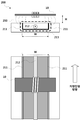
도 2는 U형 급전장치를 개략적으로 도시하는 도면.
도 3은 I형 급전장치를 개략적으로 도시하는 도면.
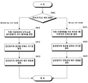
도 4는 공리설계 이론에 따른 급전장치의 설계방법을 나타내는 순서도.
도 5는 급집전장치의 최적설계 방법을 나타내는 순서도.
도 6은 자기유도방식으로 전력을 공급 및 집전하는 급집전장치를 설계하는 장치를 나타내는 도면.
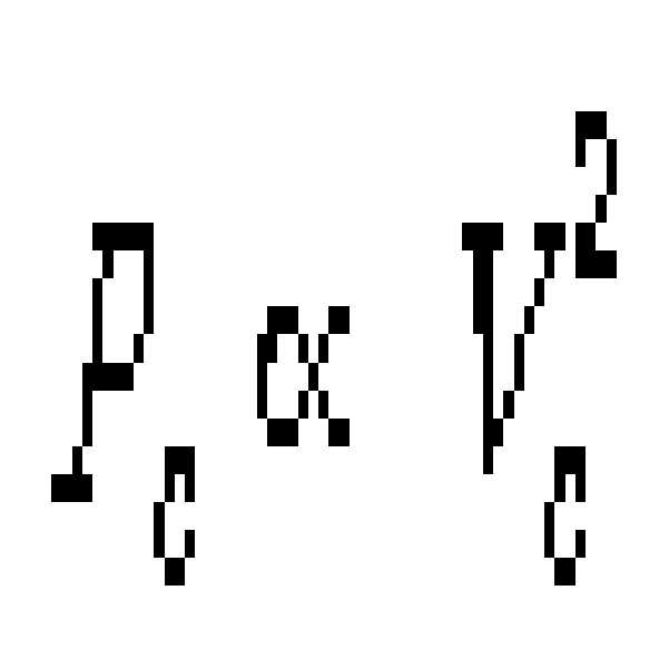
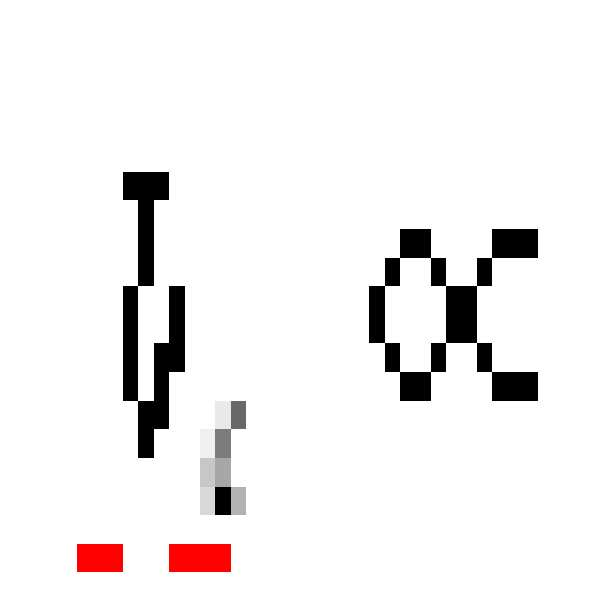



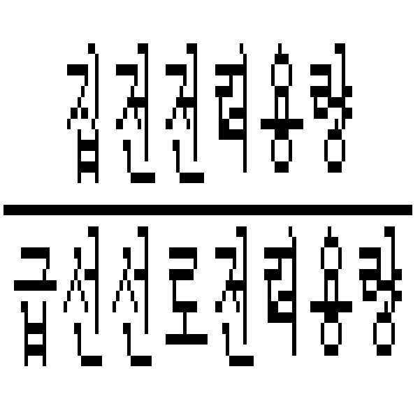


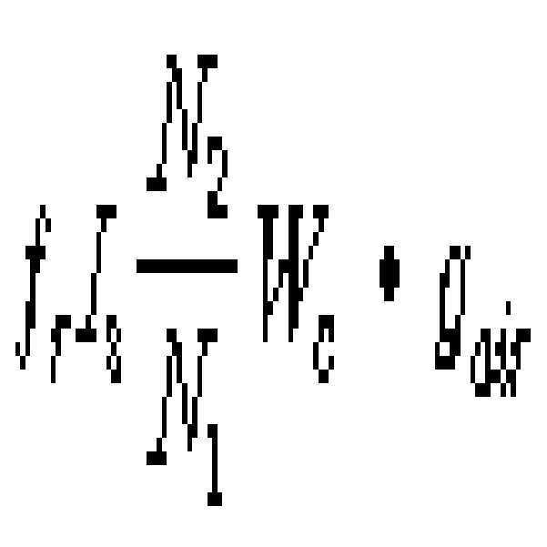
10, 20: 집전장치
200: U형 급전장치
211: U형 급전장치의 코어(자극)
212: U형 급전장치의 급전선
213: U형 급전코어 단면
300: I형 급전장치
311: I형 급전장치의 코어(자극)
312, 313: I형 급전장치의 급전선
250, 350: 급전장치에 의해 형성된 자기장
600: 급전장치 설계 장치
610: 설계 프로세스 제어부
620: 집전용량 산출부
630: EMF 레벨 산출부
640: 이격거리 산출부
650: 설계 파라미터 데이터베이스
660: 입력부
670: 설계화면 제공부
Claims (25)
- 집전장치를 갖는 차량에 무선으로 전력을 공급하기 위한 급전장치를 설계하는 방법으로서,
(a) 급전장치와 집전장치 사이의 간격을 입력받는 단계;
(b) 상기 급전장치와 집전장치 사이의 간격에 기초하여 급집전 코어 폭 또는 급전장치의 인접하는 두 자극 사이의 간격을 결정하는 단계;
(c) 급전장치에서 발생되는 자기장의 크기에 대해 요구되는 값을 입력받는 단계; 및
(d) 상기 단계(b)에서 결정된 급집전 코어 폭 또는 급전장치의 인접하는 두 자극 사이의 간격, 및 상기 자기장의 크기에 대해 요구되는 값에 기초하여 급전장치에 공급될 전력의 크기를 결정하는 단계
를 포함하는 것을 특징으로 하는 급전장치 설계 방법. - 청구항 1에 있어서,
상기 단계(d) 이후에,
(d1) 급전장치에 전력을 공급하는 전선의 배치 방법을 결정하는 단계
를 더 포함하는 것을 특징으로 하는 급전장치 설계 방법. - 청구항 1에 있어서,
상기 단계(a) 이전에,
급전장치의 자극의 배열 방향을 입력받는 단계
를 더 포함하는 것을 특징으로 하는 급전장치 설계 방법. - 청구항 3에 있어서,
급전장치의 자극의 배열 방향은,
둘 이상의 자극이 차량 진행방향과 평행하게 연장되고 서로 나란한 것
을 특징으로 하는 급전장치 설계 방법. - 청구항 3에 있어서,
급전장치의 자극의 배열 방향은,
다수의 자극이 차량 진행방향을 따라 직렬로 배열된 것
을 특징으로 하는 급전장치 설계 방법. - 청구항 1에 있어서,
상기 단계(d) 이후에,
(d2) 급전장치 및 집전장치에서 발생하는 전자기장(EMF)에 대한 능동 또는 수동 차폐 방식을 결정하는 단계
를 더 포함하는 것을 특징으로 하는 급전장치 설계 방법. - 청구항 1에 있어서,
상기 단계(d) 이후에,
(d3) 급전장치 스위치의 온오프 상태를 결정하는 단계
를 더 포함하는 것을 특징으로 하는 급전장치 설계 방법. - 청구항 1에 있어서,
상기 단계(d) 이후에,
(d4) 급전장치에서 발생하는 교류 자기장의 주파수에, 차량에 부착된 집전장치를 공진시킬 것을 결정하는 단계
를 더 포함하는 것을 특징으로 하는 급전장치 설계 방법. - 자기장을 발생시킴으로써 집전장치를 갖는 차량에 무선으로 전력을 공급하는 급전장치 및 집전장치를 설계하는 방법으로서,
(a) 공진주파수, 급전전류값, 급집전 코어 폭 및 집전코일 권수를 포함하는 설계 파라미터를 초기값으로 설정하는 단계;
(b) 집전장치에 요구되는 최소 집전용량 값(이하 '집전용량 기준값'이라 한다) 및 급집전장치에서 발생허용되는 최대 EMF 값(이하 'EMF 기준값'이라 한다)을 입력받는 단계;
(c) 현재 설정된 설계 파라미터로부터 집전용량 및 발생하는 전자파(EMF) 레벨을 산출하는 단계;
(d) 산출된 집전용량이 상기 집전용량 기준값 미만이거나 발생 EMF 레벨이 EMF 기준값 초과(이하 "설계조건 불만족"이라 한다)인 경우 설정된 설계 파라미터 중 급전전류값을 조정하면서 집전용량 및 발생 EMF 레벨 산출을 반복하는 단계; 및
(e) 산출된 집전용량이 상기 집전용량 기준값 이상이고 발생하는 전자파(EMF) 레벨이 상기 EMF 기준값 이하(이하 "설계조건 만족"이라 한다)가 되게하는 급전전류값이 존재하는 경우, 그 급전전류값 및 현재 설정되어 있는 타 설계 파라미터 값을 최종 설계 파라미터로서 결정하는 단계
를 포함하는 급집전장치 설계 방법. - 청구항 9에 있어서,
상기 단계(e)에서,
설계조건 만족시키는 급전전류값이 존재하는 경우, 현재 설정되어 있는 설계 파라미터 값을 최종 설계 파라미터로서 결정하기 전에,
(e11) 현재 설정된 공진주파수 값이 허용 범위 내의 최대 공진주파수(이하 '상한 공진주파수'라 한다)보다 작으면, 상기 설계 파라미터 중 공진주파수를 상기 상한 공진주파수 이하의 범위에서 상향 조정하면서 집전용량 산출 및 발생되는 EMF 레벨 산출을 반복하여 설계조건 만족시키는 최대 공진주파수를 구하는 단계
를 더 포함하고, 이후,
(e12) 상기 단계(e11)에서 결정된 최대 공진주파수, 상기 단계(e)의 급전전류값 및 현재 설정되어 있는 타 설계 파라미터 값을 최종 설계 파라미터로서 결정하는 단계
를 포함하는 것을 특징으로 하는 급집전장치 설계 방법. - 청구항 9에 있어서,
상기 단계(e)에서,
설계조건 만족시키는 급전전류값이 존재하지 않는 경우, 현재 설정되어 있는 설계 파라미터 값을 최종 설계 파라미터로서 결정하기 전에,
(e21) 급집전 코어 폭 또는 자극간 간격(이하 '급집전 코어 폭'으로 통칭한다)을 허용범위 내에서 증가시키고 급전전류값을 조정하면서 집전용량 산출 및 발생되는 EMF 레벨 산출을 반복하는 단계;
(e22) 설계조건 만족시키는 급집전 코어 폭 및 급전전류값이 존재하지 않으면 급전장치 설계과정을 종료하고, 존재하는 경우 단계(e23)으로 진행하는 단계;
(e23) 현재 설정된 공진주파수 값이 허용 범위 내의 최대 공진주파수(이하 '상한 공진주파수'라 한다)보다 작으면, 상기 설계 파라미터 중 공진주파수를 상기 상한 공진주파수 이하의 범위에서 상향 조정하면서 집전용량 산출 및 발생되는 EMF 레벨 산출을 반복하여 설계조건 만족시키는 최대 공진주파수를 구하는 단계
를 더 포함하고, 이후,
(e24) 상기 단계(e23)에서 결정된 최대 공진주파수, 상기 단계(e22)의 급전전류값 및 현재 설정되어 있는 타 설계 파라미터 값을 최종 설계 파라미터로서 결정하는 단계
를 포함하는 것을 특징으로 하는 급집전장치 설계 방법. - 청구항 9에 있어서,
상기 단계(d)에서, 조정하는 설계 파라미터에는 집전코일의 권수를 더 포함하고,
상기 단계(e)에서, 존재여부를 판단하고 최종 설계 파라미터로서 결정하는 설계 파라미터에는 집전코일의 권수를 더 포함하는 것
을 특징으로 하는 급집전장치 설계 방법. - 청구항 9에 있어서,
상기 공진 주파수 값은,
최대 가청 주파수 값보다 큰 값으로 결정하는 것
을 특징으로 하는 급집전장치 설계 방법. - 청구항 9 내지 청구항 13 중 어느 한 항에 있어서,
설계조건 만족 여부의 판단에는,
급전장치와 집전장치 간의 이격거리가, 기 설정된 최소 이격거리 이상이 되는지에 대한 판단이 더 포함되는 것
을 특징으로 하는 급집전장치 설계 방법. - 자기장을 발생시킴으로써 집전장치를 갖는 차량에 무선으로 전력을 공급하는 급전장치를 설계하는 방법으로서,
(a) 공진주파수, 급전전류값, 급집전 코어 폭 및 집전코일 권수를 포함하는 설계 파라미터를 결정할 급집전장치의 코어 구조 타입(type)을 입력받는 단계;
(b) 상기 설계 파라미터를 초기값으로 설정하는 단계;
(c) 집전장치에 요구되는 최소 집전용량 값(이하 '집전용량 기준값'이라 한다) 및 급집전장치에서 발생허용되는 최대 EMF 값(이하 'EMF 기준값'이라 한다)을 입력받는 단계;
(d) 현재 설정된 설계 파라미터로부터 집전용량 및 발생하는 전자파(EMF) 레벨을 산출하는 단계;
(e) 산출된 집전용량이 상기 집전용량 기준값 미만이거나 발생 EMF 레벨이 EMF 기준값 초과(이하 "설계조건 불만족"이라 한다)인 경우 설정된 설계 파라미터 중 급전전류값을 조정하면서 집전용량 및 발생 EMF 레벨 산출을 반복하는 단계; 및
(f) 산출된 집전용량이 상기 집전용량 기준값 이상이고 발생하는 전자파(EMF) 레벨이 상기 EMF 기준값 이하(이하 "설계조건 만족"이라 한다)가 되게 하는 급전전류값이 존재하는 경우, 그 급전전류값 및 현재 설정되어 있는 타 설계 파라미터 값을 상기 코어 구조 타입에 대한 최종 설계 파라미터로서 결정하는 단계
를 포함하는 급집전장치 설계 방법. - 청구항 15에 있어서,
상기 단계(a)에서, 둘 이상의 코어 구조 타입이 입력된 경우,
각 코어 구조 타입에 대하여 순차적으로 상기 단계(b) 내지 단계(f)를 수행하는 것
을 특징으로 하는 급집전장치 설계 방법. - 청구항 15에 있어서,
상기 단계(f)에서,
설계조건 만족시키는 급전전류값이 존재하는 경우, 현재 설정되어 있는 설계 파라미터 값을 최종 설계 파라미터로서 결정하기 전에,
(f11) 현재 설정된 공진주파수 값이 허용 범위 내의 최대 공진주파수(이하 '상한 공진주파수'라 한다)보다 작으면, 상기 설계 파라미터 중 공진주파수를 상기 상한 공진주파수 이하의 범위에서 상향 조정하면서 집전용량 산출 및 발생되는 EMF 레벨 산출을 반복하여 설계조건 만족시키는 최대 공진주파수를 구하는 단계
를 더 포함하고, 이후,
(f12) 상기 단계(f11)에서 결정된 최대 공진주파수, 상기 단계(f)의 급전전류값 및 현재 설정되어 있는 타 설계 파라미터 값을 최종 설계 파라미터로서 결정하는 단계
를 포함하는 것을 특징으로 하는 급집전장치 설계 방법. - 청구항 15에 있어서,
상기 단계(f)에서,
설계조건 만족시키는 급전전류값이 존재하지 않는 경우, 현재 설정되어 있는 설계 파라미터 값을 최종 설계 파라미터로서 결정하기 전에,
(f21) 급집전 코어 폭 또는 자극간 간격(이하 '급집전 코어 폭'으로 통칭한다)을 허용범위 내에서 증가시키고 급전전류값을 조정하면서 집전용량 산출 및 발생되는 EMF 레벨 산출을 반복하는 단계;
(f22) 설계조건 만족시키는 급집전 코어 폭 및 급전전류값이 존재하지 않으면 급전장치 설계과정을 종료하고, 존재하는 경우 단계(f23)으로 진행하는 단계;
(f23) 현재 설정된 공진주파수 값이 허용 범위 내의 최대 공진주파수(이하 '상한 공진주파수'라 한다)보다 작으면, 상기 설계 파라미터 중 공진주파수를 상기 상한 공진주파수 이하의 범위에서 상향 조정하면서 집전용량 산출 및 발생되는 EMF 레벨 산출을 반복하여 설계조건 만족시키는 최대 공진주파수를 구하는 단계
를 더 포함하고, 이후,
(f24) 상기 단계(f23)에서 결정된 최대 공진주파수, 상기 단계(f22)의 급전전류값 및 현재 설정되어 있는 타 설계 파라미터 값을 최종 설계 파라미터로서 결정하는 단계
를 포함하는 것을 특징으로 하는 급집전장치 설계 방법. - 청구항 15에 있어서,
상기 단계(e)에서, 조정하는 설계 파라미터에는 집전코일의 권수를 더 포함하고,
상기 단계(f)에서, 존재여부를 판단하고 최종 설계 파라미터로서 결정하는 설계 파라미터에는 집전코일의 권수를 더 포함하는 것
을 특징으로 하는 급집전장치 설계 방법. - 청구항 15에 있어서,
상기 공진 주파수 값은,
최대 가청 주파수 값보다 큰 값으로 결정하는 것
을 특징으로 하는 급집전장치 설계 방법. - 청구항 15 내지 청구항 20 중 어느 한 항에 있어서,
설계조건 만족 여부의 판단에는,
급전장치와 집전장치 간의 이격거리가, 기 설정된 최소 이격거리 이상이 되는지에 대한 판단이 더 포함되는 것
을 특징으로 하는 급집전장치 설계 방법. - 자기장을 발생시킴으로써 집전장치를 갖는 차량에 무선으로 전력을 공급하는 급전장치 및 집전장치를 설계하는 장치로서,
공진주파수, 급전전류값, 급집전 코어 폭 및 집전코일 권수를 포함하는 설계 파라미터로부터 집전용량을 산출하는 집전용량 산출부;
상기 설계 파라미터로부터 발생하는 전자파(EMF) 레벨을 산출하는 EMF 레벨 산출부;
상기 설계 파라미터 값 및 상기 각 설계 파라미터의 변동가능 범위값을 저장하는 설계 파라미터 데이터베이스;
사용자로부터 상기 각 설계 파라미터 값, 상기 각 설계 파라미터의 변동가능 범위값 및, 요청되는 집전용량 및 EMF 레벨 값을 포함하는 설계조건 기준값을 입력받는 입력부;
설계과정에서 산출되는 데이터, 설계조건 기준값 및 결정되는 설계 파라미터 값을 포함하는 설계과정의 각종 데이터를 디스플레이해 주는 설계화면 제공부; 및
기 설정된 범위의 집전용량 및 EMF 레벨을 만족하는 급집전장치를 설계하기 위하여, 상기 각 구성요소를 제어하여 각 설계 파라미터의 변동에 따른 집전용량 및 EMF 레벨 산출 및, 이에 따른 설계 파라미터의 결정 과정을 제어하는 설계 프로세스 제어부
를 포함하는 급집전장치 설계 장치. - 청구항 22에 있어서,
상기 설계 파라미터에는,
상기 급집전 코어 구조 타입을 더 포함하는 것
을 특징으로 하는 급집전장치 설계 장치. - 청구항 22에 있어서,
상기 설계조건 기준값에는,
급전장치와 집전장치 간의 최소 이격거리 값이 더 포함되는 것
을 특징으로 하는 급집전장치 설계 장치. - 청구항 22에 있어서,
상기 설계 파라미터로부터 급전장치와 집전장치 간의 이격거리를 산출하는 이격거리 산출부
를 더 포함하는 것을 특징으로 하는 급집전장치 설계 장치.
Priority Applications (9)
| Application Number | Priority Date | Filing Date | Title |
|---|---|---|---|
| KR1020100068470A KR101156034B1 (ko) | 2010-07-15 | 2010-07-15 | 전기 자동차를 이용하는 운송 시스템의 급집전장치 설계 방법 및 장치 |
| SG2013003264A SG187089A1 (en) | 2010-07-15 | 2011-02-09 | Method and device for designing a current supply and collection device for a transportation system using an electric vehicle |
| CN201180034518.1A CN103003091B (zh) | 2010-07-15 | 2011-02-09 | 利用电动车的运输系统的供集、电装置的设计方法及装置 |
| PCT/KR2011/000867 WO2012008672A1 (ko) | 2010-07-15 | 2011-02-09 | 전기 자동차를 이용하는 운송 시스템의 급집전장치 설계 방법 및 장치 |
| JP2013519562A JP2013538541A (ja) | 2010-07-15 | 2011-02-09 | 電気自動車を用いる運送システムの給集電装置設計方法及び装置 |
| AU2011277322A AU2011277322B2 (en) | 2010-07-15 | 2011-02-09 | Method and device for designing a current supply and collection device for a transportation system using an electric vehicle |
| US13/810,066 US9747391B2 (en) | 2010-07-15 | 2011-02-09 | Method and device for designing a current supply and collection device for a transportation system using an electric vehicle |
| EP11806957.4A EP2594425A4 (en) | 2010-07-15 | 2011-02-09 | Method and device for designing a current supply and collection device for a transportation system using an electric vehicle |
| JP2015053758A JP2015164394A (ja) | 2010-07-15 | 2015-03-17 | 電気自動車を用いる運送システムの給集電装置設計方法及び装置 |
Applications Claiming Priority (1)
| Application Number | Priority Date | Filing Date | Title |
|---|---|---|---|
| KR1020100068470A KR101156034B1 (ko) | 2010-07-15 | 2010-07-15 | 전기 자동차를 이용하는 운송 시스템의 급집전장치 설계 방법 및 장치 |
Publications (2)
| Publication Number | Publication Date |
|---|---|
| KR20120007775A true KR20120007775A (ko) | 2012-01-25 |
| KR101156034B1 KR101156034B1 (ko) | 2012-06-18 |
Family
ID=45469645
Family Applications (1)
| Application Number | Title | Priority Date | Filing Date |
|---|---|---|---|
| KR1020100068470A Active KR101156034B1 (ko) | 2010-07-15 | 2010-07-15 | 전기 자동차를 이용하는 운송 시스템의 급집전장치 설계 방법 및 장치 |
Country Status (8)
| Country | Link |
|---|---|
| US (1) | US9747391B2 (ko) |
| EP (1) | EP2594425A4 (ko) |
| JP (2) | JP2013538541A (ko) |
| KR (1) | KR101156034B1 (ko) |
| CN (1) | CN103003091B (ko) |
| AU (1) | AU2011277322B2 (ko) |
| SG (1) | SG187089A1 (ko) |
| WO (1) | WO2012008672A1 (ko) |
Cited By (2)
| Publication number | Priority date | Publication date | Assignee | Title |
|---|---|---|---|---|
| KR101879938B1 (ko) * | 2016-06-29 | 2018-07-18 | 한국기술교육대학교 산학협력단 | 역자기장선을 이용한 전기자동차용 급전장치 구조 |
| KR20190009237A (ko) * | 2017-07-18 | 2019-01-28 | 한국과학기술원 | 전기적으로 독립적인 복수개의 코일을 갖는 무선 집전장치 및 이의 제어방법 |
Families Citing this family (10)
| Publication number | Priority date | Publication date | Assignee | Title |
|---|---|---|---|---|
| KR20130135830A (ko) | 2010-07-08 | 2013-12-11 | 메르크 파텐트 게엠베하 | 반전도성 중합체 |
| WO2013168241A1 (ja) * | 2012-05-09 | 2013-11-14 | トヨタ自動車株式会社 | 車両 |
| GB2502084A (en) * | 2012-05-14 | 2013-11-20 | Bombardier Transp Gmbh | Arrangement for providing vehicles with energy comprising magnetisable material |
| JP6022267B2 (ja) * | 2012-09-05 | 2016-11-09 | 昭和飛行機工業株式会社 | 移動給電式の非接触給電装置 |
| CN106061789A (zh) * | 2014-03-04 | 2016-10-26 | 株式会社泰库诺瓦 | 行驶中非接触供电系统 |
| US20170046452A1 (en) * | 2015-08-14 | 2017-02-16 | VERTICA Lukasz Rutkiewicz | Device for digital modeling of actual surfaces |
| EP3352328B1 (en) * | 2015-09-18 | 2020-12-02 | FUJI Corporation | Non-contact power supply device |
| CN108683272B (zh) * | 2018-06-25 | 2021-07-30 | 哈尔滨工业大学 | 一种用于动态无线充电的双极型发射导轨 |
| CN117178175A (zh) * | 2021-04-23 | 2023-12-05 | 索尼集团公司 | 光检测装置 |
| CN115664050A (zh) * | 2022-11-08 | 2023-01-31 | 同济大学 | 基于高阶Anti-PT对称的多负载无线电能传输系统 |
Family Cites Families (12)
| Publication number | Priority date | Publication date | Assignee | Title |
|---|---|---|---|---|
| JP2000092615A (ja) | 1998-09-09 | 2000-03-31 | Harness Syst Tech Res Ltd | 電気自動車用充電システムにおける充電カプラーの位置検出方法及びその装置 |
| US6811344B1 (en) * | 1999-02-03 | 2004-11-02 | Kabushiki Kaisha Toshiba | Computer-aided designing assistant apparatus and method of assisting designing of environmentally conscious product |
| JP2003189508A (ja) * | 2001-12-14 | 2003-07-04 | Furukawa Electric Co Ltd:The | 非接触電力供給装置 |
| GB0210886D0 (en) * | 2002-05-13 | 2002-06-19 | Zap Wireless Technologies Ltd | Improvements relating to contact-less power transfer |
| US20080250330A1 (en) * | 2003-02-26 | 2008-10-09 | Carl Thompson | Portable action processing software module with pre-designed expert action plans |
| US7272809B2 (en) * | 2003-11-13 | 2007-09-18 | International Business Machines Corporation | Method, apparatus and computer program product for implementing enhanced high frequency return current paths utilizing decoupling capacitors in a package design |
| DE102006060330A1 (de) | 2006-12-20 | 2008-06-26 | Mahle International Gmbh | Einsatz für eine Zylinderlaufbuchse oder einem Zylinder eines Verbrennungsmotors |
| US8030888B2 (en) * | 2007-08-13 | 2011-10-04 | Pandya Ravi A | Wireless charging system for vehicles |
| KR20090067715A (ko) | 2007-12-21 | 2009-06-25 | 김국진 | 내구성이 강한 신발 |
| KR100940240B1 (ko) | 2008-09-02 | 2010-02-04 | 한국과학기술원 | 전기 자동차를 이용하는 운송 시스템 |
| JP5329929B2 (ja) * | 2008-12-02 | 2013-10-30 | 昭和飛行機工業株式会社 | 非接触給電装置 |
| KR100944113B1 (ko) * | 2009-02-27 | 2010-02-24 | 한국과학기술원 | 전기자동차용 전원공급 시스템 및 방법 |
-
2010
- 2010-07-15 KR KR1020100068470A patent/KR101156034B1/ko active Active
-
2011
- 2011-02-09 EP EP11806957.4A patent/EP2594425A4/en not_active Withdrawn
- 2011-02-09 CN CN201180034518.1A patent/CN103003091B/zh not_active Expired - Fee Related
- 2011-02-09 WO PCT/KR2011/000867 patent/WO2012008672A1/ko not_active Ceased
- 2011-02-09 SG SG2013003264A patent/SG187089A1/en unknown
- 2011-02-09 JP JP2013519562A patent/JP2013538541A/ja active Pending
- 2011-02-09 US US13/810,066 patent/US9747391B2/en active Active
- 2011-02-09 AU AU2011277322A patent/AU2011277322B2/en active Active
-
2015
- 2015-03-17 JP JP2015053758A patent/JP2015164394A/ja active Pending
Cited By (2)
| Publication number | Priority date | Publication date | Assignee | Title |
|---|---|---|---|---|
| KR101879938B1 (ko) * | 2016-06-29 | 2018-07-18 | 한국기술교육대학교 산학협력단 | 역자기장선을 이용한 전기자동차용 급전장치 구조 |
| KR20190009237A (ko) * | 2017-07-18 | 2019-01-28 | 한국과학기술원 | 전기적으로 독립적인 복수개의 코일을 갖는 무선 집전장치 및 이의 제어방법 |
Also Published As
| Publication number | Publication date |
|---|---|
| SG187089A1 (en) | 2013-02-28 |
| JP2015164394A (ja) | 2015-09-10 |
| US20130304443A1 (en) | 2013-11-14 |
| AU2011277322B2 (en) | 2014-09-18 |
| CN103003091A (zh) | 2013-03-27 |
| JP2013538541A (ja) | 2013-10-10 |
| KR101156034B1 (ko) | 2012-06-18 |
| AU2011277322A1 (en) | 2013-02-07 |
| WO2012008672A1 (ko) | 2012-01-19 |
| EP2594425A1 (en) | 2013-05-22 |
| CN103003091B (zh) | 2015-10-21 |
| EP2594425A4 (en) | 2018-02-28 |
| US9747391B2 (en) | 2017-08-29 |
Similar Documents
| Publication | Publication Date | Title |
|---|---|---|
| KR101156034B1 (ko) | 전기 자동차를 이용하는 운송 시스템의 급집전장치 설계 방법 및 장치 | |
| Soares et al. | A study on renewed perspectives of electrified road for wireless power transfer of electric vehicles | |
| US9156364B2 (en) | Wireless power charging using point of load controlled high frequency power converters | |
| ElGhanam et al. | Design of a high power, lcc-compensated, dynamic, wireless electric vehicle charging system with improved misalignment tolerance | |
| Tan et al. | Design and optimization of ground-side power transmitting coil parameters for EV dynamic wireless charging system | |
| Sathik Mohamed Ali et al. | A comprehensive review of the on-road wireless charging system for E-mobility applications | |
| US20150246614A1 (en) | Inductive power coupling systems for roadways | |
| CN102290875B (zh) | 通过高频交变磁场给电动汽车在行驶中提供电力的装置 | |
| CN103931079A (zh) | 共振频率变化也可维持传输效率稳定性的供集电系统 | |
| Brenna et al. | Modelling and simulation of electric vehicle fast charging stations driven by high speed railway systems | |
| Ushkewar et al. | Wireless charging in a dynamic environment for electric vehicles | |
| Prasanth et al. | Green energy based inductive Self-Healing highways of the future | |
| Fadhel et al. | Principal challenges for designing an efficient wireless power transfer for electric vehicles | |
| KR101259155B1 (ko) | 전기자동차용 집전장치 | |
| KR101356030B1 (ko) | 집전 및 급전 시스템과 그를 위한 집전 장치, 급전 구조물 | |
| Hasan | Optimization and control of lumped transmitting coil-based in-motion wireless power transfer systems | |
| Bharathi et al. | Wireless Power Transfer Systems for Electric Vehicle Application based on IoT | |
| KR101587126B1 (ko) | 급전 선로에 따른 급전 장치 및 그를 이용한 급집전 장치 | |
| Cho et al. | Shaped magnetic field in resonance technology and its application to transportation system | |
| Nissimagoudar et al. | Graphene-Based Wireless Power Transmission: Charge as You Drive | |
| CN106712316A (zh) | 无线充电方法、设备及电动汽车 | |
| Kalaiselvan et al. | Optimal design of high efficiency wireless charging system for electric vehicle: AHO–GBDT technique | |
| GD et al. | Solar Based Wireless Power Charging and Electric Vehicle Using Roadway Coil | |
| Singaravelan et al. | Design and Implementation of Wireless Charger for EV With High Alignment Tolerance: Gannet Optimization Algorithm (GOA) | |
| Russer et al. | Wireless Inductive Power Supply of Electric Vehicles while Driving Along the Route |
Legal Events
| Date | Code | Title | Description |
|---|---|---|---|
| A201 | Request for examination | ||
| PA0109 | Patent application |
Patent event code: PA01091R01D Comment text: Patent Application Patent event date: 20100715 |
|
| PA0201 | Request for examination | ||
| E902 | Notification of reason for refusal | ||
| PE0902 | Notice of grounds for rejection |
Comment text: Notification of reason for refusal Patent event date: 20110804 Patent event code: PE09021S01D |
|
| PG1501 | Laying open of application | ||
| E701 | Decision to grant or registration of patent right | ||
| PE0701 | Decision of registration |
Patent event code: PE07011S01D Comment text: Decision to Grant Registration Patent event date: 20120521 |
|
| GRNT | Written decision to grant | ||
| PR0701 | Registration of establishment |
Comment text: Registration of Establishment Patent event date: 20120607 Patent event code: PR07011E01D |
|
| PR1002 | Payment of registration fee |
Payment date: 20120608 End annual number: 3 Start annual number: 1 |
|
| PG1601 | Publication of registration | ||
| FPAY | Annual fee payment |
Payment date: 20151204 Year of fee payment: 4 |
|
| PR1001 | Payment of annual fee |
Payment date: 20151204 Start annual number: 4 End annual number: 4 |
|
| FPAY | Annual fee payment |
Payment date: 20160607 Year of fee payment: 5 |
|
| PR1001 | Payment of annual fee |
Payment date: 20160607 Start annual number: 5 End annual number: 5 |
|
| FPAY | Annual fee payment |
Payment date: 20180525 Year of fee payment: 7 |
|
| PR1001 | Payment of annual fee |
Payment date: 20180525 Start annual number: 7 End annual number: 7 |
|
| FPAY | Annual fee payment |
Payment date: 20190603 Year of fee payment: 8 |
|
| PR1001 | Payment of annual fee |
Payment date: 20190603 Start annual number: 8 End annual number: 8 |
|
| PR1001 | Payment of annual fee |
Payment date: 20200525 Start annual number: 9 End annual number: 9 |
|
| PR1001 | Payment of annual fee |
Payment date: 20210601 Start annual number: 10 End annual number: 10 |
|
| PR1001 | Payment of annual fee |
Payment date: 20220607 Start annual number: 11 End annual number: 11 |
|
| PR1001 | Payment of annual fee |
Payment date: 20240527 Start annual number: 13 End annual number: 13 |