KR20120036730A - Feeder apparatus for metal strip - Google Patents
Feeder apparatus for metal strip Download PDFInfo
- Publication number
- KR20120036730A KR20120036730A KR1020110036769A KR20110036769A KR20120036730A KR 20120036730 A KR20120036730 A KR 20120036730A KR 1020110036769 A KR1020110036769 A KR 1020110036769A KR 20110036769 A KR20110036769 A KR 20110036769A KR 20120036730 A KR20120036730 A KR 20120036730A
- Authority
- KR
- South Korea
- Prior art keywords
- block
- reciprocating
- cam
- metal strip
- pin
- Prior art date
- Legal status (The legal status is an assumption and is not a legal conclusion. Google has not performed a legal analysis and makes no representation as to the accuracy of the status listed.)
- Granted
Links
Images








Classifications
-
- B—PERFORMING OPERATIONS; TRANSPORTING
- B65—CONVEYING; PACKING; STORING; HANDLING THIN OR FILAMENTARY MATERIAL
- B65H—HANDLING THIN OR FILAMENTARY MATERIAL, e.g. SHEETS, WEBS, CABLES
- B65H20/00—Advancing webs
- B65H20/20—Advancing webs by web-penetrating means, e.g. pins
- B65H20/22—Advancing webs by web-penetrating means, e.g. pins to effect step-by-step advancement of web
-
- B—PERFORMING OPERATIONS; TRANSPORTING
- B21—MECHANICAL METAL-WORKING WITHOUT ESSENTIALLY REMOVING MATERIAL; PUNCHING METAL
- B21D—WORKING OR PROCESSING OF SHEET METAL OR METAL TUBES, RODS OR PROFILES WITHOUT ESSENTIALLY REMOVING MATERIAL; PUNCHING METAL
- B21D43/00—Feeding, positioning or storing devices combined with, or arranged in, or specially adapted for use in connection with, apparatus for working or processing sheet metal, metal tubes or metal profiles; Associations therewith of cutting devices
- B21D43/02—Advancing work in relation to the stroke of the die or tool
- B21D43/04—Advancing work in relation to the stroke of the die or tool by means in mechanical engagement with the work
- B21D43/06—Advancing work in relation to the stroke of the die or tool by means in mechanical engagement with the work by positive or negative engaging parts co-operating with corresponding parts of the sheet or the like to be processed, e.g. carrier bolts or grooved section in the carriers
-
- B—PERFORMING OPERATIONS; TRANSPORTING
- B21—MECHANICAL METAL-WORKING WITHOUT ESSENTIALLY REMOVING MATERIAL; PUNCHING METAL
- B21D—WORKING OR PROCESSING OF SHEET METAL OR METAL TUBES, RODS OR PROFILES WITHOUT ESSENTIALLY REMOVING MATERIAL; PUNCHING METAL
- B21D53/00—Making other particular articles
- B21D53/02—Making other particular articles heat exchangers or parts thereof, e.g. radiators, condensers fins, headers
-
- B—PERFORMING OPERATIONS; TRANSPORTING
- B21—MECHANICAL METAL-WORKING WITHOUT ESSENTIALLY REMOVING MATERIAL; PUNCHING METAL
- B21D—WORKING OR PROCESSING OF SHEET METAL OR METAL TUBES, RODS OR PROFILES WITHOUT ESSENTIALLY REMOVING MATERIAL; PUNCHING METAL
- B21D53/00—Making other particular articles
- B21D53/02—Making other particular articles heat exchangers or parts thereof, e.g. radiators, condensers fins, headers
- B21D53/022—Making the fins
-
- B—PERFORMING OPERATIONS; TRANSPORTING
- B65—CONVEYING; PACKING; STORING; HANDLING THIN OR FILAMENTARY MATERIAL
- B65H—HANDLING THIN OR FILAMENTARY MATERIAL, e.g. SHEETS, WEBS, CABLES
- B65H20/00—Advancing webs
- B65H20/20—Advancing webs by web-penetrating means, e.g. pins
Landscapes
- Engineering & Computer Science (AREA)
- Mechanical Engineering (AREA)
- Advancing Webs (AREA)
- Transmission Devices (AREA)
Abstract
본 발명의 금속 스트립의 이송 장치는, 관통구멍이 형성되어 있는 금속 스트립을 소정의 방향으로 이송할 때에, 프레스 장치의 구동 수단에 의해 왕복운동 가능하게 설치된 왕복운동 블록; 상기 왕복운동 블록의 상방에 배치되어 있으며, 상기 왕복운동 블록의 이동 방향으로 이동하는 연결부재에 연결되어 있는 이동 블록; 선단부가 기준 플레이트에 놓여있는 금속 스트립의 관통구멍 속으로 삽입되는 이송 핀을 구비하고 있으며, 상기 이동 블록과 함께 이동하는 핀 블록; 그리고 상기 핀 블록을 상승시키고 하강시키는 상-하부 캠부를 포함하고 있다. 상기 이동 블록은, 상기 왕복운동 블록에 의해 견인되지 않도록 형성 되어 있고, 상기 이송 장치는 이동 블록을 왕복운동 블록의 왕복운동과는 별개로 왕복운동시키기 위한 이동 블록 구동 수단을 더 포함하고 있다.The conveying apparatus of the metal strip of this invention is a reciprocating block provided so that a reciprocating motion by the drive means of a press apparatus, when conveying the metal strip in which the through-hole is formed in the predetermined direction; A moving block disposed above the reciprocating block and connected to a connecting member moving in a movement direction of the reciprocating block; A pin block having a tip end inserted into a through hole of a metal strip placed on a reference plate, the pin block moving together with the moving block; And an upper and lower cam portion for raising and lowering the pin block. The moving block is formed so as not to be towed by the reciprocating block, and the transfer device further includes a moving block driving means for reciprocating the moving block separately from the reciprocating motion of the reciprocating block.
Description
본 발명은, 복수개의 관통구멍이 이송 방향으로 소정의 간격으로 형성되어 있는 금속 스트립을 소정의 방향으로 이송하는 이송 장치에 관한 것이다.The present invention relates to a conveying apparatus for conveying a metal strip in which a plurality of through holes are formed at predetermined intervals in a conveying direction in a predetermined direction.
에어 컨디셔너와 같은 열교환기는, 열교환 튜브를 삽입할 수 있는 복수개의 관통구멍이 형성되어 있는 복수개의 열교환기용 핀을 적층하여 구성되어 있다. 이러한 열교환기용 핀은, 도 14에 도시되어 있는 열교환기용 핀의 제조장치에 의해 제조된다. 열교환기용 핀의 제조장치에는, 알루미늄 등으로 만들어진 금속제 박판(또는 "금속 스트립")(10)이 코일 모양으로 감긴 언코일러(uncoiler)(12)가 설치되어 있다. 언코일러(12)로부터 핀치 롤러(14)를 거쳐서 풀려나온 금속 스트립(10)은 오일 부여 장치(16) 속으로 삽입되고, 이 오일 부여 장치(16)에서 가공용 오일이 금속 스트립(10)의 표면에 도포된 다음, 프레스 장치(18) 내부에 설치되어 있는 금형장치(20)로 공급된다.A heat exchanger such as an air conditioner is configured by stacking a plurality of heat exchanger fins having a plurality of through holes into which heat exchange tubes can be inserted. Such a heat exchanger fin is manufactured by the apparatus for manufacturing a heat exchanger fin shown in FIG. In the apparatus for manufacturing heat exchanger fins, an
상기 금형장치(20)는 내부에 상하 이동가능한 상부 몰드 다이세트(22)와 정지상태에 있는 하부 몰드 다이세트(24)를 포함하고 있다. 이 금형장치(20)를 통과한 금속 스트립(10)에는, 형성되어 있는 관통구멍의 주위에 소정 높이의 칼라(collar)가 형성되어 있는 복수의 칼라 부착 관통구멍(11)(본 명세서에서는 단지 "관통구멍" 이라고 칭할 경우가 있다)이 소정의 방향으로 소정의 간격을 두고 형성되어 있다. 이러한 금속 스트립(10)은, 소정의 방향으로 소정의 거리만큼 이송된 후, 커터(26)에 의해 소정의 길이로 절단된 후, 스태커(stacker)(28)에 저장된다.The
프레스 장치(18)에는, 소정의 방향으로 소정의 간격을 두고 복수개의 관통구멍(11)이 형성되어 있는 금속 스트립(10)을 커터(26) 쪽으로 간헐적으로 이송하는 이송 장치가 설치되어 있다.The
도 15 및 도 16과 관련하여 이송 장치의 동작에 의한 금속 스트립(10)의 이송에 관하여 설명한다. 이송 장치는, 금속 스트립(10)에 형성되어 있는 관통구멍(11) 속으로 이송 핀(68)을 아래쪽으로부터 삽입하여, 이송 핀(68)을 이송 방향으로 이동시킴으로써 금속 스트립(10)을 이송 방향으로 이송시킨다.The transfer of the
금속 스트립(10)은 기준 플레이트(64) 위에 놓여 있다. 기준 플레이트(64)에는, 이송 핀(68)의 이동 범위에 걸쳐서 뻗어 있는 슬릿(66)이 형성되어 있다. 이 슬릿(66)으로부터 이송 핀(68)이 상방으로 돌출되어 있다.The
이송 핀(68)은, 수평 방향 및 상하 방향으로 이동가능한 핀 블록(56)에 상방을 향해서 돌출하도록 설치되어 있다.The
금속 스트립(10)이 이송 방향으로 이송될 때에는, 핀 블록(56)이 상승하고, 기준 플레이트(64)에 놓여있는 금속 스트립(10)의 관통구멍(11) 속으로 이송 핀(68)이 삽입된다. 그리고, 핀 블록(56)이 이송 방향으로 이동한다. 금속 스트립(10)을 소정의 위치까지 이동시킨 후, 핀 블록(56)이 하강하고, 이송 핀(68)이 관통구멍(11)으로부터 하방으로 빠져나온다. 그 후, 이송 핀(68)이 금속 스트립(10)과 접촉하지 않는 위치에 있는 상태에서, 핀 블록(56)이 초기 위치로 돌아가기 위해 이송 방향과 반대 방향("복귀 방향")으로 이동한다.When the
다음에, 도 17 내지 도 19에 기초하여 종래의 이송 장치의 구체적인 구조와 그 동작에 관하여 설명한다.Next, the specific structure and operation | movement of the conventional conveyance apparatus are demonstrated based on FIG. 17-19.
상기 이송 장치는, 이송 방향으로 왕복운동하는 왕복운동 블록(50) 및 이 왕복운동 블록(50)의 상부에 설치되어 있는 이동 블록(54)을 포함하고 있다. 이 이동 블록(54)은, 왕복운동 블록(50)의 양 단부 근처에서 서로 상대하여 고정되어 있는 2개의 고정부재(82a ,82b) 사이에, 왕복운동 블록(50)의 이동 방향과 동일한 방향으로 이동할 수 있게 현수된 상태로 설치되어 있는 샤프트(60)에 고정되어 있다. 이 때문에, 이동 블록(54)은 샤프트(60)과 함께 왕복운동 블록(50)의 이동 방향으로 이동가능하다.The conveying apparatus includes a reciprocating
이송 핀(68)을 보유하는 핀 블록(56)은, 이동 블록(54)의 상부에 설치되어 있으며 서로 상하로 배치되어 있는 2개의 플레이트(56a, 56b)를 가지고 있다. 핀 블록(56)은, 상기 플레이트(56a, 56b)의 사이에 복수의 이송 핀(68)이 끼워지도록 부착되어 있다.The
핀 블록(56)은, 도면에 도시되어 있지 않은 스프링과 같은 탄성가압 수단에 의해 아래쪽(이동 블록(54)측)으로 탄성가압되어 있다. 이 때문에, 핀 블록(56)은 이동 블록(54)과 함께 이동할 수 있고, 탄성가압 수단의 탄성가압력에 저항하는 위쪽방향의 힘이 핀 블록(56)에 작용하면, 핀 블록(56)은 기준 플레이트(64) 쪽으로 상승한다.The
이동 블록(54)과 핀 블록(56)의 사이에는, 상-하부 캠부(80)가 설치되어 있다. 상-하부 캠부(80)는, 핀 블록(56)에 고정 설치된 상부 캠부(76)와 이동 블록(54)에 설치된 하부 캠부(78)로 구성되어 있다. 상부 캠부(76) 및 하부 캠부(78)의 각각의 대향면에는 요철부가 형성되어 있다.An upper and
상기 하부 캠부(78)는, 2개의 고정부재(82a, 82b)의 사이에 위치되어 있는 이동 블록(54)위에 놓여 있으며 이동 블록(54)보다도 폭이 넓은 광폭 부재(78a)의 상부면에 형성되어 있다. 광폭 부재(78a)는, 이송 방향의 양 단부로부터 이동 블록(54) 및 핀 블록(56)을 넘어서 돌출하도록 적절한 크기로 형성되어 있다.The
상부 캠부(76)의 요철부는, 광폭 부재(78a)의 하부 캠부(78)와 상대하는 대향면에 형성되어 있다.The uneven part of the
광폭 부재(78a)는 이동 블록(54) 위를 미끄럼이동할 수 있으며, 광폭 부재(78a)의 이러한 이동은 고정부재(82a, 82b)에 의해 규제된다. 다시 말해서, 광폭 부재(78a)가 이송 방향으로 미끄럼이동하면, 광폭 부재(78a)의 이송 방향측 단부는 고정부재(82b)의 내측 벽면에 맞닿고, 광폭 부재(78a)가 이송 방향과 반대 방향으로 미끄럼이동하면, 광폭 부재(78a)의 금속 스트립(10)의 이송 방향의 반대쪽 단부는 고정부재(82a)의 내측 벽면에 맞닿는다.The
도 19에 나타나 있는 바와 같이, 광폭 부재(78a)의 이송 방향측 단부가 고정부재(82b)에 맞닿을 경우에는, 상부 캠부(76)와 하부 캠부(78)에 각각 형성되어 있는 볼록부가 서로 맞닿는다. 이 때문에, 핀 블록(56)은 탄성가압 수단의 탄성가압력에 저항해서 상방으로 가압되고 핀 블록(56)에 설치되어 있는 이송 핀(68, 68, ...)의 선단부가 기준 플레이트(64)에 놓여 있는 금속 스트립(10)의 관통구멍(11) 속으로 진입한다.As shown in FIG. 19, when the conveyance direction side end part of the
한편, 도 17 및 도 18에 나타나 있는 바와 같이, 광폭 부재(78a)가 이송 방향(즉, 고정부재(82b)쪽 방향)으로 미끄럼이동하고 광폭 부재(78a)의 다른 단부가 고정부재(82b)에 맞닿을 경우에는, 상부 캠부(76)와 하부 캠부(78)에 형성되어 있는 오목부와 볼록부가 서로 끼워맞추어 진다. 이 때문에, 핀 블록(56)은 탄성가압 수단의 탄성가압력에 의해 이동 블록(54)에 대해 가압되고 핀 블록(56)의 이송 핀(68, 68, ...)의 선단부는 기준 플레이트(64)에 놓여 있는 금속 스트립(10)의 관통구멍(11)로부터 빠져 나온다.On the other hand, as shown in Figs. 17 and 18, the
이러한 금속 스트립(10)의 이송 장치에 있어서, 기준 플레이트(64)에 놓여있는 금속 스트립(10)은 고정 블록(52b) 방향으로 이송되고, 이송된 후는 그 위치에서 금속 스트립(10)을 위치 결정하기 위한 위치 결정 핀(84)이 설치되어 있다. 이 위치 결정 핀(84)은 고정 블록(52b)으로부터 상방으로 돌출하도록 설치되어 있다. 위치 결정 핀(84)은 고정 블록(52b)에 설치되어 있는 위치 결정 캠부(86)에 의해 상하로 이동한다.In the conveying device of this
위치 결정 캠부(86)는, 서로 상대하는 각각의 대향면에 형성되어 있는 요철부를 가지고 있는 상부 캠부(86a)와 하부 캠부(86b)로 구성 되어 있고, 하부 캠부(86b)는 고정 블록(52b)보다도 폭이 넓고 또한 미끄럼이동가능하게 형성되어 있는 광폭 부재(87)에 형성되어 있다.The
하부 캠부(86b)가 양 캠부의 볼록부끼리 접합하는 방향으로 미끄럼이동하면, 위치 결정 핀(84)의 선단부는 기준 플레이트(64) 위로 돌출하여 기준 플레이트(64)에 놓여 있는 금속 스트립(10)의 관통구멍(11) 내부로 삽입되어, 금속 스트립(10)을 위치결정한다.When the
한편, 하부 캠부(86b)가 캠부의 볼록부와 오목부가 끼워맞추어지는 방향으로 미끄럼이동하면, 위치 결정 핀(84)의 선단부는 기준 플레이트(64)의 기준면 아래에 위치하게 되고, 기준 플레이트(64)에 놓여 있는 금속 스트립(10)의 칼라 부착 관통구멍(11)으로부터 빠져 나와서, 금속 스트립(10)의 위치결정을 해제한다.On the other hand, when the
하부 캠부(86b)의 광폭 부재(87)는, 고정 블록(52b)과 상대하는 고정 블록(52a)에 미끄럼이동가능하게 삽입되는 미끄럼이동 부재(88)와 샤프트(90)에 의해 연결되어 있다. 상기 샤프트(90)는, 이송 방향을 따라서 서로 상대하여 배치된 2개의 고정 블록(52a, 52b) 사이에 걸쳐 있도록 배치되어 있다. 샤프트(90)는 왕복운동 블록(50)을 관통해서 배치되어 있고, 왕복운동 블록(50)의 이동을 방해하지 않도록 설치되어 있다.The
왕복운동 블록(50)이 이송 방향으로 이동하였을 때, 왕복운동 블록(50)의 이동 방향측 단부가 하부 캠부(86b)의 광폭 부재(87)의 단부를 누르므로, 하부 캠부(86b)는 상하부 캠부(86a, 86b)의 볼록부가 접합하는 방향으로 미끄럼이동한다. 왕복운동 블록(50)이 이동 방향과 반대 방향으로 이동하였을 때, 왕복운동 블록(50)의 이동 방향의 반대쪽 단부가 샤프트(90)의 광폭 부재(87)가 설치되어 있는 측에 대해 샤프트(90)의 반대측에 설치되어 있는 미끄럼이동 부재(88)의 단부를 누르므로, 하부 캠부(86b)는 상하부 캠부(86a, 86b)의 오목부와 볼록부가 서로 끼워맞추어 지는 방향으로 미끄럼이동한다.When the
다음에는 도 20 및 도 21에 의거하여 이동 블록의 이동 동작에 관하여 설명한다.Next, the movement operation of the moving block will be described with reference to FIGS. 20 and 21.
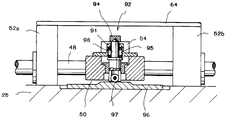
이동 블록(54)은, 도면에 도시되어 있지 않은 스프링에 의해 왕복운동 블록(50)의 중앙부에 유지되어 있다. 왕복운동 블록(50)에는, 이동 블록(54)을 왕복운동 블록(50)의 소정의 위치에 확실하게 유지시키는 유지수단(92)이, 왕복운동 블록(50)으로부터 돌출하도록 설치되어 있다. 상기 유지수단(92)은 왕복운동 블록(50)으로부터 이동 블록(54) 쪽으로 돌출되어 있으며 그 선단부가 이동 블록(54)에 결합되는 핀 부재(98)를 가지고 있다. 상기 핀 부재(98)는 왕복운동 블록(50)의 이동에 따라 이동 블록(54)의 유지와 유지해제를 행할 수 있도록 구성되어 있다. 핀 부재(98)의 하단부에는 이송 방향을 따라서 회전하는 바퀴(97)가 설치되어 있고, 상기 바퀴(97)은 탄성가압 수단(95)에 의해 항상 아래쪽을 향해서 탄성가압되어 있다.The moving
왕복운동 블록(50)의 하부에는, 상방으로 돌출되어 있는 사다리꼴 형상부를 가진 캠 부재(96)가 배치되어 있다. 이 캠 부재(96)의 표면에, 바퀴(97)가 설치되어 있는 핀 부재(98)의 하단부가 탄성가압 수단(95)의 탄성가압력에 의해 맞닿아 있다.Under the
바퀴(97)가 캠 부재(96)의 사다리꼴 형상부에 위치할 때, 핀 부재(98)의 선단부는 상승하여 이동 블록(54)의 오목부 속으로 삽입되어서 핀 부재(98)와 이동 블록(54)은 결합된다. 그 후, 유지수단(92)은, 이동 블록(54)을 왕복운동 블록(50)의 소정의 위치에 확실하게 유지할 수 있다.When the
한편, 이동 블록(54)의 이동이 종단 근방의 위치 도달했을 때, 바퀴(97)는 캠 부재(96)의 사다리꼴 형상부보다 낮은 위치에 위치하게 되고, 핀 부재(98)의 선단부는 이동 블록(54)의 오목부로부터 빠져 나와서, 핀 부재(98)와 이동 블록(54)의 결합이 해제된다.On the other hand, when the movement of the moving
상기한 구성을 가진 이송 장치에서는, 캠 부재의 사다리꼴 형상부에 핀 부재의 하단부가 올라 앉아 있기 때문에 핀 부재가 상하로 이동하고, 핀 부재가 이동 블록에 이런 방식으로 연결됨으로써, 왕복운동 블록의 이동에 따라서 이동 블록이 이동할 수 있게 된다.In the transfer device having the above-described configuration, since the lower end of the pin member sits on the trapezoidal portion of the cam member, the pin member moves up and down, and the pin member is connected to the moving block in this manner, thereby moving the reciprocating block. According to this, the moving block can move.
다시 말해서, 이동 블록이 이동을 시작하기 전에 이미 왕복운동 블록은 이동을 하고, 정지하고 있던 이동 블록이 갑자기 왕복운동 블록의 이동속도와 동일한 속도로 이동을 시작하기 때문에, 이동 블록이 이동을 시작할 때에는 급가속이 발생한다.In other words, since the reciprocating block already moves before the moving block starts to move, and the moving block that has been stopped suddenly starts moving at the same speed as the moving speed of the reciprocating block, the moving block starts to move. Rapid acceleration occurs.
한편, 정지시에서도, 이동 블록의 측면이 스톱퍼에 맞닿아 있어서 이동 블록이 갑자기 정지하기 때문에, 정지시에도 급감속이 발생한다.On the other hand, even during the stop, since the side surface of the moving block is in contact with the stopper and the moving block suddenly stops, rapid deceleration occurs even during the stop.
이와 같이, 종래의 이송 장치에서는, 이송 핀을 이동시키는 이동 블록이 급가속 및 급감속을 함으로써 금속 스트립이 이송되었다. 그러나, 이송 핀이 관통구멍에 삽입된 금속 스트립을 급가속 및 급감속해서 이송하는 종래의 이송 장치에서는, 제품으로 사용되는 금속 스트립에 대단히 큰 부하가 가해지는 문제점이 있다. 특히 최근에는, 금속 스트립이 대단히 얇아지고 있어서, 큰 부하가 가해지는 것으로 인해서 제품의 변형 등의 우려가 있다. 또한 급가속 및 급감속을 수반하는 이송 방법에서는, 금속 스트립의 이송 정밀도가 나빠지는 문제점도 있다.Thus, in the conventional conveying apparatus, the metal strip was conveyed by the rapid acceleration and deceleration of the moving block which moves the conveying pin. However, in the conventional conveying apparatus for rapidly accelerating and rapidly decelerating a metal strip inserted into a through hole, a very large load is applied to the metal strip used as a product. In particular, in recent years, metal strips have become very thin, and there is a fear of deformation of the product due to a large load being applied. Moreover, in the conveyance method with rapid acceleration and deceleration, there also exists a problem that the conveyance precision of a metal strip worsens.
본 발명은 상기한 문제점을 해결하기 위해 창안된 것으로서, 급가속 및 급감속을 발생시키지 않고 금속 스트립을 이송할 수 있는 이송 장치를 제공하는 것을 목적으로 한다.The present invention has been made to solve the above problems, and an object of the present invention is to provide a conveying apparatus capable of conveying a metal strip without generating rapid acceleration and rapid deceleration.
본 발명에 따른 이송 장치는 복수의 관통구멍이 형성되어 있는 금속 스트립을 소정의 방향으로 이송하고, 금속 스트립이 놓이는 상부면을 가지고 있으며, 상부면과 하부면을 연결되게 관통하여 금속 스트립의 이송 방향으로 뻗어 있는 슬릿을 가지고 있는 기준 플레이트; 상기 기준 플레이트의 하방에 설치되어 있으며, 구동 수단에 의해 상기 기준 플레이트와 평행하게 금속 스트립의 이송 방향 및 그 반대 방향으로 왕복운동하는 왕복운동 블록; 상기 왕복운동 블록의 상방에 배치되어 있으며, 상기 왕복운동 블록의 왕복운동 방향에 대하여 직교하는 상기 왕복운동 블록의 양쪽 단부 근방의 서로 상대하여 고정된 고정부재로 이루어지는 한 쌍의 고정부재 사이에서, 상기 왕복운동 블록의 이동 방향으로 이동가능하게 배치되어 있는 연결부재에 연결되어 있는 이동 블록; 상기 이동 블록과 함께 이동가능하고 또한 상기 기준 플레이트쪽으로 상하로 이동가능하게 설치되어 있으며, 선단부가 상기 기준 플레이트에 놓여있는 금속 스트립의 관통구멍 속으로 삽입되는 이송 핀이 설치되어 있는 핀 블록; 그리고 상기 핀 블록에 고정 설치된 상부 캠부와 상기 상부 캠부에 상대해서 상기 이동 블록에 설치되어 있는 하부 캠부로 구성되어 있으며, 상기 왕복운동 블록이 금속 스트립의 이송 방향으로 이동할 때에는, 상기 이송 핀의 선단부가 상기 기준 플레이트의 슬릿으로 진입하여, 상기 기준 플레이트에 놓여있는 금속 스트립의 관통구멍 속으로 삽입되도록 상기 핀 블록을 상기 기준 플레이트 방향으로 밀어 올리고, 상기 왕복운동 블록이 금속 스트립의 이송 방향에 대하여 반대 방향으로 이동할 때에는, 상기 이송 핀의 선단부가 상기 기준 플레이트에 놓여있는 금속 스트립의 관통구멍으로부터 빠져나가도록 상기 핀 블록을 상기 왕복운동 블록 방향으로 밀어 내리는 상-하부 캠부;를 포함하고 있고, 상기 이동 블록은, 왕복운동하는 상기 왕복운동 블록에 의해서 견인되지 않도록 형성되어 있으며, 상기 이송 장치는 상기 이동 블록을 상기 왕복운동 블록의 왕복운동과는 별개로 왕복운동시키기 위한 이동 블록 구동 수단을 더 포함하고 있다.The conveying apparatus according to the present invention conveys a metal strip in which a plurality of through holes is formed in a predetermined direction, has an upper surface on which the metal strip is placed, and penetrates the upper and lower surfaces so as to be connected to the conveying direction of the metal strip. A reference plate having slits extending inwardly; A reciprocating block disposed below the reference plate, the reciprocating block reciprocating in the conveying direction and the opposite direction of the metal strip in parallel with the reference plate by a drive means; Between the pair of fixing members disposed above the reciprocating block, the pair of fixing members comprising fixed members fixed to each other near both ends of the reciprocating block orthogonal to the reciprocating direction of the reciprocating block, A moving block connected to the connection member movably disposed in the movement direction of the reciprocating block; A pin block movable together with the moving block and movable up and down toward the reference plate, the pin block having a feed pin inserted into a through hole of a metal strip on which the tip is placed on the reference plate; And an upper cam portion fixed to the pin block and a lower cam portion provided in the moving block relative to the upper cam portion. When the reciprocating block moves in the conveying direction of the metal strip, the tip portion of the conveying pin is Enter the slit of the reference plate, push the pin block in the direction of the reference plate to be inserted into the through hole of the metal strip lying on the reference plate, the reciprocating block in the opposite direction to the conveying direction of the metal strip And an upper-lower cam portion for pushing the pin block in the direction of the reciprocating block so that the distal end of the transfer pin exits from the through hole of the metal strip placed on the reference plate. Silver, the reciprocating block reciprocating It is formed so as not to be towed by, the transfer device further comprises a moving block drive means for reciprocating the moving block separately from the reciprocating motion of the reciprocating block.
상기 구성을 채용함으로써, 왕복운동 블록의 동작에 따라서 이동 블록이 이동하는 것을 방지할 수 있어서, 이동 블록이 왕복운동 블록의 동작과는 별개로 동작할 수 있게 된다. 이 때문에, 종래 기술에서와 같이, 왕복운동 블록이 이동 블록에 견인력(pull)을 작용하는 것으로 인한 급가속 및 급감속을 방지할 수 있고, 또한 금속 스트립에 가해지는 부하를 경감할 수도 있다.By adopting the above configuration, it is possible to prevent the moving block from moving in accordance with the operation of the reciprocating block, so that the moving block can operate independently of the operation of the reciprocating block. For this reason, as in the prior art, it is possible to prevent rapid acceleration and sudden deceleration caused by the reciprocating block exerting a pull on the moving block, and also reduce the load on the metal strip.
상기 이동 블록 구동 수단은, 상기 이동 블록의 측면을 가압하여 상기 이동 블록을 이송 방향으로 이동시키도록 동작하는 캠을 포함할 수 있다. 이러한 구성에 의하면, 캠의 형상에 따라 이동 블록의 이동을 제어할 수 있다.The moving block driving means may include a cam operable to press the side surface of the moving block to move the moving block in a conveying direction. According to such a structure, the movement of a movement block can be controlled according to the shape of a cam.
상기 캠은, 상기 이동 블록이 초기 위치로부터 이송 방향으로 이동을 개시한 직후에 상기 이동 블록의 속도가 서서히 증가하고, 이송 방향의 종단 위치에 도달하기 전에 상기 이동 블록의 속도가 서서히 감소하도록 하는 모양으로 형성될 수 있다. 이러한 구성에 의하면, 캠의 형상에 따라 점진적인 가속 및 점진적인 감속이 이루어지게 이동 블록을 이동시킬 수 있고, 결과적으로 금속 스트립에 가해지는 부하를 경감시킬 수 있다.The cam has a shape such that the speed of the moving block gradually increases immediately after the moving block starts moving in the conveying direction from the initial position, and the speed of the moving block gradually decreases before reaching the end position of the conveying direction. It can be formed as. According to this configuration, it is possible to move the moving block to achieve gradual acceleration and gradual deceleration depending on the shape of the cam, and consequently to reduce the load on the metal strip.
또한, 상기 캠은 플레이트 캠으로 될 수 있고, 상기 캠과 상기 이동 블록의 사이에는, 상기 캠의 둘레방향의 가장자리부 및 상기 이동 블록의 측면의 쌍방에 맞닿는 캠 종동자(cam follower)가 설치될 수 있다. 이러한 구성에 의하면, 캠이 직접 이동 블록을 가압하지 않기 때문에, 캠의 동작을 스무스하게 행할 수 있다.In addition, the cam may be a plate cam, and a cam follower is provided between the cam and the movable block, which is in contact with both the circumferential edge of the cam and the side surface of the movable block. Can be. According to this structure, since the cam does not directly press the moving block, the cam can be smoothly operated.
상기 이송 장치는 상기 이동 블록을 이송 방향의 종단 위치로부터 초기 위치쪽으로 탄성가압하는 탄성가압 수단을 더 포함할 수 있고, 이 경우 상기 탄성가압 수단은 상기 이동 블록에 있어서 상기 캠이 맞닿는 측면과 반대측의 측면에 설치되어 있다. 이러한 구성에 의하면, 캠에 의해 이송 방향의 종단 위치까지 이동 블록이 이동한 후, 탄성가압 수단의 탄성가압력에 의해 이동 블록이 초기 위치로 되돌아 가도록 이동된다. 다시 말해서, 이송 방향의 종단 위치에서 초기 위치까지 이동 블록이 되돌아갈 때에는, 이송 핀이 하강된 위치에 있고 금속 스트립의 이송은 없다. 이 때문에, 금속 스트립에는 부하가 가해지지 않고, 이러한 복귀 동작은 위치 정밀도와 관계가 없다. 따라서, 초기 위치까지 이동 블록을 되돌리는 것은 탄성가압 수단에 의하면 충분하고, 이로 인해 구조가 단순화될 수 있고 비용도 절감될 수 있다.The conveying apparatus may further include elastic pressing means for elastically pressing the moving block from an end position in a conveying direction to an initial position, wherein the elastic pressing means is opposite to a side on which the cam abuts on the moving block. It is installed on the side. According to this configuration, after the moving block is moved to the end position in the conveying direction by the cam, the moving block is moved to return to the initial position by the elastic pressing force of the elastic pressing means. In other words, when the moving block is returned from the end position in the conveying direction to the initial position, the conveying pin is in the lowered position and there is no conveyance of the metal strip. For this reason, no load is applied to the metal strip, and this return operation is independent of the positional accuracy. Therefore, returning the moving block to the initial position is sufficient by the elastic pressing means, which can simplify the structure and reduce the cost.
상기 이송 장치는 위치결정 핀을 더 포함할 수 있고, 이 경우 상기 왕복운동 블록이 금속 스트립의 이송 방향으로 이동할 때에는, 상기 위치결정 핀의 선단부가 상기 기준 플레이트의 상부면 아래에 위치하고, 상기 왕복운동 블록이 금속 스트립의 이송 방향에 대하여 반대 방향으로 이동할 때에는, 상기 위치결정 핀의 선단부가 상기 기준 플레이트의 상부면에 놓여있는 금속 스트립의 관통구멍 속으로 삽입되어, 금속 스트립을 소정의 위치에 위치결정한다. 이러한 구성에 의하면, 왕복운동 블록이 이송 방향과 반대 방향으로 이동할 때에는, 금속 스트립을 위치 결정한 상태에 정지시켜 둘 수 있다. 이 때문에, 금속 스트립의 관통구멍을 다음 공정으로 이송하여 관통구멍에 기계가공을 수행할 때에, 관통구멍의 위치 어긋남 등을 바로잡기 위해 다시 위치결정 동작을 수행할 필요가 없고, 이로 인해 가공 속도의 향상을 도모할 수 있다.The conveying device may further comprise a positioning pin, in which case the tip of the positioning pin is located below the upper surface of the reference plate when the reciprocating block moves in the conveying direction of the metal strip, and the reciprocating motion When the block moves in a direction opposite to the conveying direction of the metal strip, the leading end of the positioning pin is inserted into the through hole of the metal strip lying on the upper surface of the reference plate, thereby positioning the metal strip at a predetermined position. do. According to this structure, when the reciprocating block moves in the direction opposite to the conveying direction, the metal strip can be stopped in the positioned state. For this reason, when the through-hole of the metal strip is transferred to the next process and the machining is performed in the through-hole, it is not necessary to perform the positioning operation again to correct the displacement of the through-hole and the like. Improvement can be aimed at.
본 발명에 의하면, 급가속 및 급감속을 발생시키지 않고 금속 스트립을 이송할 수 있다. 이 때문에, 이송 대상이 되는 금속 스트립에 과대한 부하가 가해지지 않으면서 이송 정밀도도 높일 수 있다.
According to the present invention, the metal strip can be transported without generating sudden acceleration and sudden deceleration. For this reason, the conveyance accuracy can also be improved, without excessive load being applied to the metal strip to be conveyed.
도 1은 본 발명에 따른 금속 스트립의 이송 장치의 평면도이다.
도 2는 도 1의 이송 장치에 있어서의 A-A 방향에서 본 측면도이다.
도 3은 도 1의 이송 장치에 있어서의 B-B 방향에서 본 측면도이다.
도 4는 도 1의 이송 장치에 있어서의 C-C 방향에서 본 정면도이다.
도 5는 구동 수단의 구성을 나타내는데 유용한 설명도이다.
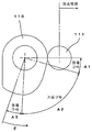
도 6은 캠과 캠 종동자의 형상을 나타내는데 유용한 설명도이다.
도 7은 캠의 회전각도와 캠 종동자의 동작 거리와의 관계를 나타내는 그래프이다.
도 8은 이동 블록이 종단 위치에 도달하고 이송 핀이 하강해 있는 지점에서의 핀 블록을 상하로 이동시키기 위한 구조를 나타내는데 유용한 설명도이다.
도 9는 이동 블록이 초기 위치쪽으로 되돌아가려고 하는 지점에서의 도 8에 도시된 구조를 나타내는데 유용한 설명도이다.
도 10은 이동 블록이 초기 위치로 되돌아간 지점에서의 도 9에 도시된 구조를 나타내는데 유용한 설명도이다.
도 11A 내지 도 11E는 왕복운동 블록의 이송 방향으로의 이동을 나타내는데 유용한 설명도이다.
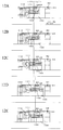
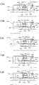
도 12A 내지 도 12E는 캠의 회전에 기초하여 이동 블록의 이송 방향으로의 이동을 나타내는데 유용한 설명도이다.
도 13A 내지 도 13E는 이동 블록의 이동 및 왕복운동 블록의 이동에 기초하여 이송 핀 및 위치 결정 핀의 상하 이동동작을 나타내는데 유용한 설명도이다.
도 14는 열교환기용 핀의 제조장치의 개략적인 구성을 설명하는데 유용한 설명도이다.
도 15는 이송 핀에 의해 금속 스트립이 이송되고 있는 상태를 나타내는데 유용한 설명도이다.
도 16은 금속 스트립이 이송된 후에 이송 핀이 초기 위치로 되돌아가는 상태를 나타내는데 유용한 설명도이다.
도 17은 이동 블록이 종단 위치에 도달하고 이송 핀이 하강해 있는 지점에서의 핀 블록을 상하로 이동시키기 위한 구조를 나타내는데 유용한 설명도이다.
도 18은 이동 블록이 초기 위치쪽으로 되돌아가려고 하는 지점에서의 도 17에 도시된 구조를 나타내는데 유용한 설명도이다.
도 19는 이동 블록이 초기 위치로 되돌아간 지점에서의 도 18에 도시된 구조를 나타내는데 유용한 설명도이다.
도 20은 종래의 이동 블록과 왕복운동 블록의 결합 구조를 나타내는데 유용한 설명도이다.
도 21은 종래의 이동 블록과 왕복운동 블록의 결합이 해제된 상태를 나타내는데 유용한 설명도이다.1 is a plan view of a conveying apparatus for a metal strip according to the present invention.
It is a side view seen from the AA direction in the transfer apparatus of FIG.
It is a side view seen from the BB direction in the conveyance apparatus of FIG.
It is a front view seen from the CC direction in the conveyance apparatus of FIG.
5 is an explanatory diagram useful in showing the configuration of the drive means.
6 is an explanatory diagram useful in showing the shapes of a cam and a cam follower.
7 is a graph showing the relationship between the rotation angle of the cam and the operation distance of the cam follower.
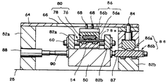
FIG. 8 is an explanatory diagram useful in showing a structure for moving the pin block up and down at the point where the moving block reaches the end position and the transfer pin is lowered.
9 is an explanatory diagram useful for showing the structure shown in FIG. 8 at the point where the moving block is going to return to the initial position.
10 is an explanatory diagram useful for showing the structure shown in FIG. 9 at the point where the moving block is returned to the initial position.
11A to 11E are explanatory diagrams useful for showing the movement of the reciprocating block in the feed direction.
12A to 12E are explanatory diagrams useful for showing the movement of the moving block in the conveying direction based on the rotation of the cam.
13A to 13E are explanatory diagrams useful for showing the vertical movement of the transfer pin and the positioning pin based on the movement of the moving block and the movement of the reciprocating block.
14 is an explanatory diagram useful for explaining a schematic configuration of an apparatus for manufacturing a heat exchanger fin.
15 is an explanatory diagram useful in showing a state in which a metal strip is being transferred by a transfer pin.
16 is an explanatory diagram useful for showing a state in which the transfer pin returns to the initial position after the metal strip is transferred.
17 is an explanatory diagram useful in showing a structure for moving the pin block up and down at the point where the moving block reaches the end position and the transfer pin is lowered.
FIG. 18 is an explanatory diagram useful in showing the structure shown in FIG. 17 at the point where the moving block is about to return to the initial position.
19 is an explanatory diagram useful for showing the structure shown in FIG. 18 at the point where the moving block is returned to the initial position.
20 is an explanatory diagram useful in showing a coupling structure of a conventional moving block and a reciprocating block.
21 is an explanatory diagram useful in showing a state in which a combination of a conventional moving block and a reciprocating block is released.
본 발명에 따른 금속 스트립의 이송 장치의 바람직한 실시형태를 이하에서 설명한다.Preferred embodiments of the conveying apparatus of the metal strip according to the present invention are described below.
도 1은 이송 장치의 평면도이다. 도 2는 도 1의 A-A 방향에서 본 이송 장치의 측면도이고, 도 3은 도 1의 B-B 방향에서 본 이송 장치의 측면도이고, 도 4는 도 1의 C-C 방향에서 본 이송 장치의 정면도이다. 이러한 이송 장치가 설치되어 있는 열교환기용 핀의 제조장치는 종래 기술에서 설명한 도 14에 도시되어 있으므로, 여기에서는 더 이상 설명하지 않는다. 또한, 종래의 기술에 있어서 설명한 구성요소와 동일한 구성요소에 대해서는 동일한 참고번호를 부여하고, 그것의 설명은 생략한다.1 is a plan view of a conveying apparatus. FIG. 2 is a side view of the conveying apparatus as viewed in the A-A direction of FIG. 1, FIG. 3 is a side view of the conveying apparatus as viewed in the B-B direction of FIG. 1, and FIG. 4 is a front view of the conveying apparatus as viewed in the C-C direction of FIG. 1. The manufacturing apparatus of the heat exchanger fin in which such a conveying apparatus is installed is shown in FIG. 14 described in the prior art, and thus will not be described herein. In addition, the same code | symbol is attached | subjected about the component same as the component demonstrated in the prior art, and the description is abbreviate | omitted.
먼저, 이송 장치의 동작의 개요를 설명한다. 이송 장치는, 금속 스트립(10)에 형성된 관통구멍(11) 속으로 복수의 이송 핀(68)을 삽입하고, 이송 핀(68)을 이동시켜서 이송 핀(68)에 의해 금속 스트립(10)을 견인력을 작용하여, 금속 스트립(10)을 소정의 위치까지 이송시키는 장치이다. 소정의 위치까지 금속 스트립(10)을 견인한 후, 이송 핀(68)은 금속 스트립(10)의 관통구멍(11)으로부터 하강하여 빠져 나와서, 초기 위치로 되돌아온다.First, the outline | summary of the operation | movement of a conveying apparatus is demonstrated. The conveying apparatus inserts a plurality of conveying
이송 장치는, 왕복운동 블록(100)과 왕복운동 블록(100)의 상방에 설치되어 있는 이동 블록(102)을 포함하고 있다. 왕복운동 블록(100)의 한 단부로부터 돌출되어 있는 돌출부(100a)에는 구동 수단을 구성하는 레버(40)의 상단부가 연결된다.The transfer apparatus includes a
도 5는 이송 장치의 왕복운동 블록(100)을 구동시키는 구동 수단을 나타내고 있다. 이 구동 수단은, 프레스 장치(18)과 동기로 회전하는 크랭크(30)의 편심 핀에 연결봉(32)을 연결하고, 핀(34)을 중심으로 하여 회전하는 제1 링크(36)와 지지점축(38)을 중심으로 하여 회동하는 레버(40)에 연결되어 있는 제2 링크(42)를 연결봉(32)의 하단부에 있는 핀(44)에 연결시킨다. 제1 링크(36)에는, 제1 링크(36)의 회전 각도를 조정하는 실린더 장치(37)가 구비되어 있다. 이와 같이, 프레스 장치(18)와 동기하고 있는 크랭크(30)의 회전에 의해서, 연결봉(32)이 제1 링크(36)와 제2 링크(42)를 통하여 레버(40)를 왕복운동시킨다.
5 shows a drive means for driving the
왕복운동 블록Reciprocating Block
왕복운동 블록(100)에는 왕복운동 방향을 따라서 기어가 형성된 래크 기어(106)가 설치되어 있다. 이 래크 기어(106)는 피니언 기어(107)와 맞물린다. 따라서, 왕복운동 블록(100)이 왕복운동 하는 것에 의해, 래크 기어(106)와 맞물리는 피니언 기어(107)가 회전한다.The
피니언 기어(107)의 회전축(108)은 복수의 베어링(109)을 통하여 길이방향으로 뻗어 있고, 이 회전축(108)에는 이동 블록(102)을 가압하는 캠(110)이 설치되어 있다. 이 캠(110)이 이동 블록(102)을 이동시키는 이동 블록 구동 수단에 해당한다. 다시 말해서, 캠(110)의 회전 동작은 피니언 기어(107)의 회전 동작에 따라 행하여진다. 피니언 기어(107)의 회전 동작은, 래크 기어(106)의 왕복운동 동작에 의해 행하여지므로, 캠(110)의 회전 동작은 레버(40)의 왕복운동에 기초하여 소정범위내(후술하는 바와 같이 약 100°의 범위내)에서의 반복적인 회전운동으로 이루어진다. The
래크 기어(106)는 왕복운동 블록(100)에 고정된 래크 베어링(115)의 상부면에 배치되어 있다. 래크 베어링(115)의 하부에는 래크 베어링(115)의 이동을 스무스하게 하기 위한 롤러(114)가 설치되어 있다.
The
이동 블록Moving block
이하에서는 이동 블록(102)의 구성 및 동작에 관하여 설명한다.Hereinafter, the configuration and operation of the moving
이동 블록(102)은 왕복운동 블록(100)의 상방에 배치되어 있고, 왕복운동 블록(100)의 왕복운동 동작에 종속하지 않는 동작으로, 금속 스트립(10)의 이송 방향으로 왕복운동한다. 이동 블록(102)의 이동 동작은, 피니언 기어(107)의 회전축(108)에 고정되어 있는 캠(110)이 이동 블록(102)의 이송 방향의 반대 방향측 단부면에 유지되어 있는 캠 종동자(111)를 누름으로써 행하여진다. 캠(110)은 피니언 기어(107)의 회전축(108)의 회전에 따라서 회전할 수 있다. 캠 종동자(111)는 캠(110)의 회전축 방향과 동일한 방향으로 뻗어 있는 회전축(113)을 통하여 이동 블록(102)의 반대 방향측 단부면에서 자유롭게 회전할 수 있도록 고정되어 있다.The moving
이동 블록(102)에는 샤프트(60)가 이동 블록(102)을 관통해서 설치되어 있고, 상기 샤프트(60)는 왕복운동 블록(100)의 이송 방향의 양단부에서 상방을 향해서 돌출하도록 설치되어 있는 2개의 고정부재(82a, 82b)의 사이에 걸쳐 설치되어 있다. 상기 샤프트(60)는 특허청구범위에 기재된 "연결부재"에 해당한다. 다시 말해서, 이동 블록(102)은 이송 방향을 따라서 배치된 샤프트(60)에 의해 가이드되도록 이동한다.The moving
왕복운동 블록(100)의 상부면의 이송 방향의 종단 위치에는, 상방으로 돌출되어 있는 종단 벽부(45)가 설치되어 있다. 이 종단 벽부(45)와 이동 블록(102)의 사이에는 스프링과 같은 탄성가압 수단(46)이 설치되어 있고, 이동 블록(102)은 탄성가압 수단(46)에 의해 항상 초기 위치쪽으로 탄성가압되어 있다.The
도 6은 하나의 캠을 평면도로 나타내고 있고, 도 7은 캠의 회전각도와 이동 블록의 이동 거리 사이의 관계를 나타내는 그래프이다.FIG. 6 shows one cam in plan view, and FIG. 7 is a graph showing the relationship between the rotational angle of the cam and the moving distance of the moving block.
각각의 캠(110)은, 일부가 원형으로 형성된 플레이트형 부재의 둘레방향의 단부면이 캠 종동자(111)에 맞닿도록 위치되어 있고, 회전축(108)의 회전에 의해 회전축(108)으로부터 바깥쪽으로 돌출되어 있는 측이 캠 종동자(111)에 맞닿으면 캠 종동자(111)가 이송 방향으로 가압된다.Each
각각의 캠(110)의 둘레방향의 단부면에는, 이동 블록(102)이 정지되는 제1정체 구역(A1)이 형성되어 있다. 이 제1정체 구역(A1)은, 캠(110)이 회전하더라도 캠 종동자(111)가 가압되지 않도록 하는 적절한 곡률 반경을 가진 원호모양으로 형성되어 있다. 캠(110)의 둘레방향의 단부면에는, 제1정체 구역(A1)에 계속하여, 이동 블록(102)이 초기 위치로부터 이동을 개시한 직후에는 급가속되지 않고 서서히 움직이기 시작하고, 그 후 서서히 이동 블록(102)이 가속되도록 하는 가동 구역(A2)이 형성되어 있다. 가동 구역(A2)의 종단 부근에 있는 부분은, 이동 블록(102)이 급정지하지 않고서 종단 위치까지 서서히 정지하도록 하는 적절한 모양으로 형성되어 있다. 캠(110)의 둘레방향의 단부면에는, 가동 구역(A2)에 계속하여, 이동 블록(102)이 정지되는 제2정체 구역(A3)이 형성되어 있다. 이 제2정체 구역(A3)은, 캠(110)이 회전하더라도 캠 종동자(111)가 가압되지 않도록 하는 적절한 곡률 반경을 가진 원호모양으로 형성되어 있다.On the end surface of the circumferential direction of each
각각의 캠(110)의 제1정체 구역(A1), 가동 구역(A2) 및 제2정체 구역(A3)은 캠(110)이 회전하는 범위(약 100도) 내에 형성되어 있고, 캠(110)의 그 밖의 부분은 캠 종동자(111)와 맞닿지 않으므로, 임의의 모양으로 형성될 수 있다. 제1정체 구역(A1)이 캠 종동자(111)와 맞닿아 있을 때에는, 이미 왕복운동 블록(100)은 이동하고 있지만, 이동 블록(102)은 이동을 시작하지 않고 여전히 정지하고 있다. 이 위치에서 이동 블록(102)이 정지하고 있는 동안, 이송 핀(68)은 상승하고 위치 결정 핀(84)은 하강한다.The first stagnation zone A1, the movable zone A2 and the second stagnation zone A3 of each
제2정체 구역(A3)이 캠 종동자(111)에 맞닿아 있을 때에는, 여전히 왕복운동 블록(100)은 이동중이지만 이동 블록(102)은 이미 정지하고 있다. 이 위치에서 이동 블록(102)이 정지하고 있는 동안, 이송 핀(68)은 하강하고 위치 결정 핀(84)은 상승한다.When the second stagnation zone A3 is in contact with the
이와 같이, 제1정체 구역(A1) 및 제2정체 구역(A3)을 설치하는 것에 의해서, 각각의 핀의 상하 위치의 전환 시간이 이동 블록(102)이 정지하고 있는 시간의 범위 내에 있다.In this way, by providing the first stagnant zone A1 and the second stagnant zone A3, the switching time of the up and down positions of the respective pins is within the range of the time when the moving
도 7에 도시되어 있는 바와 같이, 캠(110)의 회전에 따라 이동하는 이동 블록(102)은, 이동 블록(102)이 정지하고 있는 상태에 계속하여, 캠(110)의 회전에 대하여 이동 블록(102)의 위치가 사인 곡선을 그리도록 동작하고, 계속하여 다시 정지하고 있는 상태로 된다. 다시 말해서, 이송 방향을 정(+)방향이라고 하고, 이송 방향과 반대 방향을 부(-)방향이라고 하면, 이동 블록(102)이 초기 위치로부터 이동을 개시할 때까지는 완만한 정의 가속도로 움직이기 시작하고, 그 후 서서히 가속도를 높여서 중간 위치에서는 최대 속도에 도달하게 된다. 그 후에, 이동 블록(102)은 중간 위치로부터 서서히 부의 가속도로 감속하고, 이동 블록(102)이 종단 위치에 접근함에 따라 더욱 완만한 부의 가속도로 되면서 이동 블록(102)이 정지한다.As shown in FIG. 7, the moving
이와 같이, 이동 블록(102)을 가압하는 캠(110)의 형상을, 이동 블록(102)의 이동에 있어서 급가속 또는 급감속이 발생하지 않도록 형성함으로써, 이동 블록(102)에 설치되어 있는 이송 핀(68)이 삽입된 금속 스트립(10)에 가해지는 부하를 경감할 수 있고, 이송 정밀도를 향상시킬 수 있다.
Thus, the feed pin provided in the
이송 핀의 동작Feed pin behavior
이동 블록(102)의 이동에 따르는 이송 핀(68)의 상하 이동은, 종래의 기술에서 설명한 것과 동일하지만, 이하에서 도 8 내지 도 10을 참고하여 다시 설명한다.The vertical movement of the
이동 블록(102)의 상부에는 핀 블록(56)이 설치되어 있다. 이 핀 블록(56)은 서로 상하로 배치된 2개의 플레이트(56a, 56b)을 가지고 있다. 핀 블록(56)은, 플레이트(56a, 56b)의 사이에 복수의 이송 핀(68)이 끼워지도록 부착되어 있다.The
핀 블록(56)은, 도면에 도시되어 있지 않은 스프링과 같은 탄성가압 수단에 의해 아래 쪽(이동 블록(102)측)으로 탄성가압되어 있다. 핀 블록(56)은 이동 블록(102)과 함께 이동할 수 있으며, 탄성가압 수단의 탄성가압력에 저항하는 상방으로 작용하는 힘이 핀 블록(56)에 작용하면, 핀 블록(56)은 기준 플레이트(64)쪽으로 상승한다.The
이동 블록(102)과 핀 블록(56)의 사이에는, 상-하부 캠부(80)가 설치되어 있다. 상-하부 캠부(80)는, 핀 블록(56)에 고정 설치된 상부 캠부(76)와 이동 블록(102)에 설치되어 있는 하부 캠부(78)로 구성되어 있다. 상부 캠부(76) 및 하부 캠부(78)의 각각의 대향면에는 볼록부 및 오목부가 형성되어 있다. 상부 캠부(76)는 핀 블록(56)의 하부에 있어서, 하방으로 돌출되어 있는 볼록부 및 오목부를 구비하고 있다. 하부 캠부(78)는 이동 블록(102) 및 핀 블록(56)를 넘어서 이송 방향의 양단부측으로 돌출되도록 형성되어 있으며 이동 블록(102)보다도 폭이 넓은(다시 말해서, 이송 방향으로 길이가 더 긴) 광폭 부재(78a)의 상부면에 형성되어 있다. 다시 말해서, 상부 캠부(76)의 볼록부 및 오목부와 하부 캠부(78)의 볼록부 및 오목부는 대향면에 형성되어 있다.An upper and
광폭 부재(78a)는 이동 블록(102)위를 미끄럼이동할 수 있으며 이러한 이동은 고정부재(82a, 82b)에 의해 규제된다. 다시 말해서, 광폭 부재(78a)가 이송 방향으로 미끄럼이동하면, 광폭 부재(78a)의 이송 방향측 단부는 고정부재(82b)의 내측 벽면에 맞닿고, 광폭 부재(78a)가 이송 방향과 반대 방향으로 미끄럼이동하면, 광폭 부재(78a)의 이송 방향의 반대측 단부는 고정부재(82a)의 내측 벽면에 맞닿는다.The
도 10에 도시되어 있는 바와 같이, 이동 블록(102)이 먼저 초기 위치로 되돌아오고 이어서 왕복운동 블록(100)이 초기 위치로 되돌아오면, 광폭 부재(78a)의 이송 방향측 단부에 고정부재(82b)가 맞닿는다. 이 때, 상부 캠부(76)와 하부 캠부(78)에 형성된 볼록부끼리 서로 맞닿는다. 이 때문에, 핀 블록(56)은 탄성가압 수단의 탄성가압력에 저항해서 상방으로 가압되고, 핀 블록(56)에 설치되어 있는 이송 핀(68, 68, ...)의 선단부가 기준 플레이트(64)에 놓여 있는 금속 스트립(10)의 칼라 부착 관통구멍(11) 속으로 진입한다.As shown in FIG. 10, when the moving
한편, 도 8에 도시되어 있는 바와 같이, 이동 블록(102)의 광폭 부재(78a)가 이송 방향(고정부재(82b)의 방향)으로 미끄럼이동해서 종단 위치에 도달하면, 이어서 왕복운동 블록(100)이 종단 위치에 도달한다. 이 때, 왕복운동 블록(100)의 광폭 부재(78a)의 다른 단부에 고정부재(82b)가 맞닿는다. 이러한 상황이 발생하면, 상부 캠부(76)와 하부 캠부(78)에 형성된 오목부와 볼록부가 서로 끼워맞추어 진다. 이 때문에, 핀 블록(56)은 탄성가압 수단의 탄성가압력에 의해 이동 블록(102)에 가압되고, 핀 블록(56)의 이송 핀(68, 68, ...)의 선단부는 기준 플레이트(64)에 놓여 있는 금속 스트립(10)의 칼라 부착 관통구멍(11)으로부터 하방으로 빠져 나간다.On the other hand, as shown in FIG. 8, when the
다시 말해서, 이동 블록(102)이 이송 방향의 종단 위치로부터 초기 위치로 되돌아왔을 때에는, 핀 블록(56)이 상방으로 가압되어서 이송 핀(68)이 상방으로 돌출하고, 이송 핀(68)이 금속 스트립(10)의 관통구멍(11) 속으로 아래쪽으로부터 삽입되어 이송 핀(68)에 의해 금속 스트립(10)을 이송할 수 있게 된다.In other words, when the moving
이동 블록(102)이 이송 방향의 종단 위치로 이동하였을 때에는, 핀 블록(56)이 하강하고, 이송 핀(68)은 금속 스트립(10)의 관통구멍(11)으로부터 아랫쪽으로 빠져 나와서 금속 스트립(10)의 이송을 종료한다.
When the moving
위치 결정 핀의 동작Positioning Pin Behavior
왕복운동 블록(100)의 이동에 따르는 위치 결정 핀(84)의 상하 이동은, 종래의 기술에서 설명한 것과 동일하지만, 이하에서 도 8 내지 도 10을 참고하여 다시 설명한다.The vertical movement of the
상기한 바와 같이, 이송 핀(68)에 의해 이송된 금속 스트립(10)은 이송된 위치에 위치 결정될 필요가 있다. 이 때문에, 이송이 종료된 후에는 위치 결정 핀(84)이 금속 스트립(10)의 관통구멍(11) 속으로 삽입되도록 위치 결정 핀(84)이 설치되어 있다.As mentioned above, the
위치 결정 핀(84)은 고정 블록(52b)으로부터 상하방향으로 돌출하도록 설치되어 있다. 위치 결정 핀(84)은 고정 블록(52b)에 설치되어 있는 위치 결정 캠부(86)에 의해 상하로 이동한다.The
위치 결정 캠부(86)는, 서로 상대하는 각각의 대향면에 형성되어 있는 오목부 및 볼록부를 가지고 있는 상부 캠부(86a)와 하부 캠부(86b)로 구성 되어 있고, 하부 캠부(86b)는 고정 블록(52b)보다도 폭이 넓고 또한 미끄럼이동가능하게 형성된 광폭 부재(87)의 상부면에 형성되어 있다.The
하부 캠부(86b)가 양 캠부의 볼록부끼리 접합하는 방향으로 미끄럼이동하면, 위치 결정 핀(84)의 선단부는 기준 플레이트(64) 위로 돌출하고 기준 플레이트(64)에 놓여 있는 금속 스트립(10)의 칼라 부착 관통구멍(11) 내부로 삽입되어, 금속 스트립(10)을 위치 결정한다.When the
한편, 하부 캠부(86b)가 캠부의 볼록부와 오목부가 끼워맞추어 지는 방향으로 미끄럼이동하면, 위치 결정 핀(84)의 선단부는 기준 플레이트(64)의 기준면보다도 아래쪽에 위치하고, 기준 플레이트(64)에 놓여 있는 금속 스트립(10)의 칼라 부착 관통구멍(11)으로부터 빠져나와서, 금속 스트립(10)의 위치 결정을 해제할 수 있다.On the other hand, when the
하부 캠부(86b)의 광폭 부재(87)는 고정 블록(52b)과 상대하는 고정 블록(52a)으로 미끄럼이동가능하게 삽입되는 미끄럼이동 부재(88)와 샤프트(90)에 의해 결합되어 있다. 샤프트(90)는 이송 방향을 따라서 서로 상대하여 배치되어 있는 2개의 고정 블록(52a, 52b) 사이에 뻗어 있도록 배치되어 있다. 상기 샤프트(90)는 왕복운동 블록(100)을 관통하여 배치되어 있고, 왕복운동 블록(100)의 이동을 방해하지 않도록 설치되어 있다.The
왕복운동 블록(100)이 이송 방향으로 이동해서 종단 위치에 도달했을 때, 왕복운동 블록(100)의 이동 방향측 단부가 하부 캠부(86b)의 광폭 부재(87)의 단부를 누르므로, 상부 캠부(86a)와 하부 캠부(86b)의 볼록부끼리 접합하는 방향으로 하부 캠부(86b)가 미끄럼이동한다.When the
왕복운동 블록(100)이 이송 방향과 반대 방향으로 이동했을 때, 왕복운동 블록(100)의 이송 방향의 반대측 단부가 샤프트(90)의 광폭 부재(87)가 설치되어 있다측과 반대측의 미끄럼이동 부재(88)의 단부를 누르므로, 상부 캠부(86a)와 하부 캠부(86b)의 오목부와 볼록부가 끼워맞추어 지는 방향으로 하부 캠부(86b)가 미끄럼이동한다.When the
이와 같이, 왕복운동 블록(100)의 왕복운동에 의해, 왕복운동 블록(100)이 이송 방향의 종단 위치에 도달했을 때에, 위치 결정 핀(84)이 금속 스트립(10)의 관통구멍(11) 속으로 진입해서 금속 스트립(10)의 위치 결정을 행하고, 왕복운동 블록(100)이 초기 위치로 되돌아왔을 때에, 위치 결정 핀(84)이 금속 스트립(10)의 관통구멍(11)으로부터 빠져 나와서 금속 스트립(10)의 위치 결정을 해제한다.
As described above, when the
전체적인 동작Overall operation
도 11A 내지 도 11E는 왕복운동 블록(100)의 이송 방향으로의 이동에 대해서 시계열적으로 도시하고 있다.11A through 11E illustrate the time series of the movement of the
도 11A 내지 도 11E에 나타나 있는 바와 같이, 레버(40)를 이송 방향으로 이동시킴으로써, 왕복운동 블록(100)이 초기 위치로부터 종단 위치로 이동한다. 이 왕복운동 블록(100)의 이동에 따라 래크 기어(106)가 수평방향으로 이동한다. 이 래크 기어(106)와 맞물려 있는 피니언 기어(107)는 래크 기어(106)의 이동에 따라 회전축(108)을 중심으로 회전한다.As shown in Figs. 11A to 11E, the
한편, 피니언 기어(107)가 회전하는 것에 의해, 피니언 기어(107)와 동축으로 설치되어 있다 캠(110)도 회전한다. 왕복운동 블록(100)은 레버(40)에 의해 직접 동작되지만, 이동 블록(102)은 레버(40)의 동작에 의해서가 아니라 캠(110)에 의해 동작한다.On the other hand, when the
도 12A 내지 도 12E 및 도 13A 내지 도 13E는 왕복운동 블록과 이동 블록의 이동 동작에 기초하여 이송 핀 및 위치 결정 핀의 상하 이동 동작을 시계열적으로 나타내고 있다.12A to 12E and 13A to 13E show the vertical movement of the transfer pin and the positioning pin in time series based on the movement operation of the reciprocating block and the movement block.
도 12A 및 도 13A는, 이동 블록(102)이 이송 핀(68)을 상승시키는 위치(초기 위치)에 있는 상태를 나타내고 있다. 이 때, 레버(40)의 동작에 의해 왕복운동 블록(100)이 이송 방향으로 이동을 시작한다. 왕복운동 블록(100)이 이동하기 시작하고 캠(110)이 회전하기 시작하더도, 캠(110)은 캠 종동자(111)를 밀어내는 형상이 아닌 위치에서 캠 종동자(111)와 맞닿는다. 따라서, 이 시점에서는, 이동 블록(102)은 아직 움직이기 시작하지 않고 정지하고 있다.12A and 13A show a state in which the moving
이 때, 광폭 부재(78a)의 이송 방향측 단부가 고정부재(82b)의 내측 벽면에 맞닿고, 핀 블록(56)이 상승하고, 이송 핀(68)이 관통구멍(11) 속으로 진입한다. 또한 이 때, 왕복운동 블록(50)의 이송 방향의 반대측 단부가 샤프트(90)의 미끄럼이동 부재(88)의 단부를 눌러서 위치 결정 핀(84)이 하강된다.At this time, the transfer direction side end portion of the
도 12B 및 도 13B는, 캠(110)의 회전에 의해 이동 블록(102)이 이동하기 시작하는 상태를 나타내고 있다.12B and 13B show a state in which the moving block 102 starts to move by the rotation of the
도 12C 및 도 13C는 이동 블록(102)의 이동 행정의 중간 위치를 나타내고 있다.12C and 13C show the intermediate position of the movement stroke of the moving
도 12D 및 도 13D는 이동 블록(102)이 종단 위치에 도달해서 정지한 상태를 나타내고 있다.12D and 13D show a state in which the moving
도 12E 및 도 13E는 이동 블록(102)이 정지한 후, 왕복운동 블록(100)이 더 이동해서 정지한 상태를 나타내고 있다. 이 때, 광폭 부재(78a)의 이송 방향과 반대 방향측 단부가 고정부재(82a)의 내측 벽면에 맞닿고, 핀 블록(56)이 하강하고, 이송 핀(68)이 관통구멍(11)으로부터 하방으로 빠져 나간다. 또한, 이 때, 왕복운동 블록(100)의 이송 방향측 단부가 샤프트(90)의 광폭 부재(87)의 단부를 눌러서 위치 결정 핀(84)을 상승시켜서 위치 결정을 수행한다.12E and 13E show a state in which the
도 12E 및 도 13E에 도시되어 있는 상태로부터 도 12A 및 도 13A에 도시되어 있는 상태로 되돌아오는 때는, 왕복운동 블록(100)은 레버(40)의 왕복운동 동작에 의해 이동하고, 이동 블록(102)은 탄성가압 수단(46)의 탄성가압력에 의해 이동한다.
When returning from the state shown in FIGS. 12E and 13E to the state shown in FIGS. 12A and 13A, the
다른 실시형태Another embodiment
상기한 실시형태에서는, 이동 블록(102)이 캠(110)의 회전에 대하여 위치가 사인 곡선을 그리도록 동작하는 예를 설명하였지만, 급가속 및 급감속이 발생하지 않으면, 이동 블록(102)이 사인 곡선을 그리도록 동작하지 않아도 된다.In the above-described embodiment, the example in which the moving
또한, 상기한 실시형태에서는, 이동 블록(102)이 이송 방향의 종단 위치에 도달하였을 때 이동 블록(102)을 초기 위치로 복귀시키는 힘은 탄성가압 수단(46)의 탄성가압력에 의해 제공되는 예를 설명하였다. 이동 블록(102)이 초기 위치로 되돌아올 때는, 이송 핀(68)이 하강하여 있으므로, 급가속 및 급감속이 발생할 수 있다. 이 때문에, 이동 블록(102)을 종단 위치로부터 초기 위치로 복귀시키기 위한 구동 수단으로서 어떠한 수단도 사용될 수 있다.Further, in the above embodiment, the force for returning the moving
이상 본 발명을 바람직한 실시형태에 의해 설명하였지만, 본 발명은 상기 실시형태에 한정되는 것이 아니고, 본 발명의 기술사상을 벗어나지 않는 범위내에서 여러가지 변형이 실시될 수 있다는 것은 자명하다.As mentioned above, although this invention was demonstrated by the preferable embodiment, it is clear that this invention is not limited to the said embodiment, A various deformation | transformation can be implemented in the range which does not deviate from the technical idea of this invention.
Claims (9)
금속 스트립이 놓이는 상부면을 가지고 있으며, 상부면과 하부면을 연결되게 관통하여 금속 스트립의 이송 방향으로 뻗어 있는 슬릿을 가지고 있는 기준 플레이트;
상기 기준 플레이트의 하방에 설치되어 있으며, 구동 수단에 의해 상기 기준 플레이트와 평행하게 금속 스트립의 이송 방향 및 그 반대 방향으로 왕복운동하는 왕복운동 블록;
상기 왕복운동 블록의 상방에 배치되어 있으며, 상기 왕복운동 블록의 왕복운동 방향에 대하여 직교하는 상기 왕복운동 블록의 양쪽 단부 근방의 서로 상대하여 고정된 고정부재로 이루어지는 한 쌍의 고정부재 사이에서, 상기 왕복운동 블록의 이동 방향으로 이동가능하게 배치되어 있는 연결부재에 연결되어 있는 이동 블록;
상기 이동 블록과 함께 이동가능하고 또한 상기 기준 플레이트쪽으로 상하로 이동가능하게 설치되어 있으며, 선단부가 상기 기준 플레이트에 놓여있는 금속 스트립의 관통구멍 속으로 삽입되는 이송 핀이 설치되어 있는 핀 블록; 그리고
상기 핀 블록에 고정 설치된 상부 캠부와 상기 상부 캠부에 상대해서 상기 이동 블록에 설치되어 있는 하부 캠부로 구성되어 있으며, 상기 왕복운동 블록이 금속 스트립의 이송 방향으로 이동할 때에는, 상기 이송 핀의 선단부가 상기 기준 플레이트의 슬릿으로 진입하여, 상기 기준 플레이트에 놓여있는 금속 스트립의 관통구멍 속으로 삽입되도록 상기 핀 블록을 상기 기준 플레이트 방향으로 밀어 올리고, 상기 왕복운동 블록이 금속 스트립의 이송 방향에 대하여 반대 방향으로 이동할 때에는, 상기 이송 핀의 선단부가 상기 기준 플레이트에 놓여있는 금속 스트립의 관통구멍으로부터 빠져나가도록 상기 핀 블록을 상기 왕복운동 블록 방향으로 밀어 내리는 상-하부 캠부;
를 포함하고 있고,
상기 이동 블록은, 왕복운동하는 상기 왕복운동 블록에 의해서 견인되지 않도록 형성되어 있고,
상기 이동 블록을 상기 왕복운동 블록의 왕복운동과는 별개로 왕복운동시키기 위한 이동 블록 구동 수단을 더 포함하고 있는 것을 특징으로 하는 금속 스트립의 이송 장치.In the conveying apparatus which conveys the metal strip in which the some through-hole was formed in the predetermined direction,
A reference plate having an upper surface on which the metal strip is placed, and having a slit extending through the upper surface and the lower surface so as to extend in a conveying direction of the metal strip;
A reciprocating block disposed below the reference plate, the reciprocating block reciprocating in the conveying direction and the opposite direction of the metal strip in parallel with the reference plate by a drive means;
Between the pair of fixing members disposed above the reciprocating block, the pair of fixing members comprising fixed members fixed to each other near both ends of the reciprocating block orthogonal to the reciprocating direction of the reciprocating block, A moving block connected to the connection member movably disposed in the movement direction of the reciprocating block;
A pin block movable together with the moving block and movable up and down toward the reference plate, the pin block having a feed pin inserted into a through hole of a metal strip on which the tip is placed on the reference plate; And
And an upper cam portion fixed to the pin block and a lower cam portion provided on the moving block relative to the upper cam portion. When the reciprocating block moves in the conveying direction of the metal strip, the tip portion of the conveying pin is Enter the slit of the reference plate, push the pin block in the direction of the reference plate to be inserted into the through hole of the metal strip lying on the reference plate, the reciprocating block in the opposite direction to the conveying direction of the metal strip An upper and lower cam portion for pushing the pin block in the direction of the reciprocating block so that the tip end of the transfer pin exits from the through hole of the metal strip placed on the reference plate;
And,
The moving block is formed so as not to be towed by the reciprocating block reciprocating,
And a movable block driving means for reciprocating the movable block separately from the reciprocating motion of the reciprocating block.
상기 이동 블록 구동 수단은, 상기 이동 블록의 측면을 가압하여 상기 이동 블록을 이송 방향으로 이동시키도록 동작하는 캠을 포함하는 것을 특징으로 하는 금속 스트립의 이송 장치.The method of claim 1,
The moving block driving means includes a cam operative to press the side of the moving block to move the moving block in a conveying direction.
상기 캠은, 상기 이동 블록이 초기 위치로부터 이송 방향으로 이동을 개시한 직후에 상기 이동 블록의 속도가 서서히 증가하고, 이송 방향의 종단 위치에 도달하기 전에 상기 이동 블록의 속도가 서서히 감소하도록 하는 모양으로 형성되어 있는 것을 특징으로 하는 금속 스트립의 이송 장치.The method of claim 2,
The cam has a shape such that the speed of the moving block gradually increases immediately after the moving block starts moving in the conveying direction from the initial position, and the speed of the moving block gradually decreases before reaching the end position of the conveying direction. Transfer device for metal strips, characterized in that formed in.
상기 캠은 플레이트 캠이며,
상기 캠과 상기 이동 블록의 사이에는, 상기 캠의 둘레방향의 가장자리부 및 상기 이동 블록의 측면의 쌍방에 맞닿는 캠 종동자가 설치되어 있는 것을 특징으로 하는 금속 스트립의 이송 장치.The method of claim 2,
The cam is a plate cam,
A cam follower is provided between the cam and the movable block, wherein a cam follower abuts against both the circumferential edge portion of the cam and the side surface of the movable block.
상기 캠은 플레이트 캠이며,
상기 캠과 상기 이동 블록의 사이에는, 상기 캠의 둘레방향의 가장자리부 및 상기 이동 블록의 측면의 쌍방에 맞닿는 캠 종동자가 설치되어 있는 것을 특징으로 하는 금속 스트립의 이송 장치.The method of claim 3, wherein
The cam is a plate cam,
A cam follower is provided between the cam and the movable block, wherein a cam follower abuts against both the circumferential edge portion of the cam and the side surface of the movable block.
상기 이동 블록을 이송 방향의 종단 위치로부터 초기 위치쪽으로 탄성가압하는 탄성가압 수단을 더 포함하고 있고, 상기 탄성가압 수단은 상기 이동 블록에 있어서 상기 캠이 맞닿는 측면과 반대측의 측면에 설치되어 있는 것을 특징으로 하는 금속 스트립의 이송 장치.The method of claim 2,
And an elastic pressing means for elastically pressing the moving block from an end position in the conveying direction to an initial position, wherein the elastic pressing means is provided on a side opposite to the side where the cam abuts on the moving block. Transfer device for metal strips.
상기 이동 블록을 이송 방향의 종단 위치로부터 초기 위치쪽으로 탄성가압하는 탄성가압 수단을 더 포함하고 있고, 상기 탄성가압 수단은 상기 이동 블록에 있어서 상기 캠이 맞닿는 측면과 반대측의 측면에 설치되어 있는 것을 특징으로 하는 금속 스트립의 이송 장치.The method of claim 3, wherein
And an elastic pressing means for elastically pressing the moving block from an end position in the conveying direction to an initial position, wherein the elastic pressing means is provided on a side opposite to the side where the cam abuts on the moving block. Transfer device for metal strips.
상기 이동 블록을 이송 방향의 종단 위치로부터 초기 위치쪽으로 탄성가압하는 탄성가압 수단을 더 포함하고 있고, 상기 탄성가압 수단은 상기 이동 블록에 있어서 상기 캠이 맞닿는 측면과 반대측의 측면에 설치되어 있는 것을 특징으로 하는 금속 스트립의 이송 장치.The method of claim 4, wherein
And an elastic pressing means for elastically pressing the moving block from an end position in the conveying direction to an initial position, wherein the elastic pressing means is provided on a side opposite to the side where the cam abuts on the moving block. Transfer device for metal strips.
위치결정 핀을 더 포함하고 있고, 상기 왕복운동 블록이 금속 스트립의 이송 방향으로 이동할 때에는, 상기 위치결정 핀의 선단부가 상기 기준 플레이트의 상부면 아래에 위치하고, 상기 왕복운동 블록이 금속 스트립의 이송 방향에 대하여 반대 방향으로 이동할 때에는, 상기 위치결정 핀의 선단부가 상기 기준 플레이트의 상부면에 놓여있는 금속 스트립의 관통구멍 속으로 삽입되어, 금속 스트립을 소정의 위치에 위치결정하는 것을 특징으로 하는 금속 스트립의 이송 장치.The method of claim 1,
Further comprising a positioning pin, wherein when the reciprocating block moves in the conveying direction of the metal strip, the distal end of the positioning pin is located below the upper surface of the reference plate, and the reciprocating block is in the conveying direction of the metal strip. When moving in the opposite direction with respect to the metal strip, the leading end of the positioning pin is inserted into the through hole of the metal strip lying on the upper surface of the reference plate, thereby positioning the metal strip at a predetermined position. Conveying device.
Applications Claiming Priority (2)
| Application Number | Priority Date | Filing Date | Title |
|---|---|---|---|
| JPJP-P-2010-228199 | 2010-10-08 | ||
| JP2010228199A JP5216064B2 (en) | 2010-10-08 | 2010-10-08 | Metal strip feeder |
Publications (2)
| Publication Number | Publication Date |
|---|---|
| KR20120036730A true KR20120036730A (en) | 2012-04-18 |
| KR101200311B1 KR101200311B1 (en) | 2012-11-12 |
Family
ID=45924350
Family Applications (1)
| Application Number | Title | Priority Date | Filing Date |
|---|---|---|---|
| KR1020110036769A Active KR101200311B1 (en) | 2010-10-08 | 2011-04-20 | Feeder apparatus for metal strip |
Country Status (4)
| Country | Link |
|---|---|
| US (1) | US8727196B2 (en) |
| JP (1) | JP5216064B2 (en) |
| KR (1) | KR101200311B1 (en) |
| CN (1) | CN102442567B (en) |
Families Citing this family (14)
| Publication number | Priority date | Publication date | Assignee | Title |
|---|---|---|---|---|
| JP5272054B2 (en) * | 2011-07-28 | 2013-08-28 | 日高精機株式会社 | Metal strip feeder |
| CN102847845A (en) * | 2012-08-30 | 2013-01-02 | 上海大俊凯电器科技有限公司 | Manufacturing method for fins with elliptical holes or approximate elliptical holes |
| JP5505913B2 (en) * | 2012-10-31 | 2014-05-28 | 日高精機株式会社 | Flat tube fin manufacturing equipment |
| EP2823908B1 (en) * | 2013-07-09 | 2016-11-30 | Schroeder + Bauer GmbH + Co. KG | Forming tool with a feeding device |
| KR101513703B1 (en) * | 2013-12-26 | 2015-04-22 | 삼성전자주식회사 | Apparatus for feeding a sheet material of press |
| JP6523464B2 (en) * | 2015-08-31 | 2019-06-05 | 日高精機株式会社 | Metal strip feeder |
| CN106180447B (en) * | 2016-08-24 | 2018-03-23 | 舟山市新龙电子设备有限公司 | A kind of band material conveying device |
| CN107598010B (en) * | 2017-09-22 | 2019-02-05 | 徐州德坤电气科技有限公司 | A control method for an automatic expansion tube system of an air conditioner fin assembly |
| CN110976685B (en) * | 2019-11-20 | 2021-05-28 | 珠海格力电器股份有限公司 | Heat exchanger fin clamping device and method and carrying system |
| CN111618145B (en) * | 2020-06-09 | 2022-03-01 | 开化凯晟环境建设有限公司 | Processing equipment of building decoration |
| JP2022179989A (en) * | 2021-05-24 | 2022-12-06 | 日高精機株式会社 | Heat radiation fin molding body carrier device |
| WO2023029021A1 (en) * | 2021-09-06 | 2023-03-09 | 无锡微研股份有限公司 | Feeding sub-mold and fin mold |
| CN113908601B (en) * | 2021-11-25 | 2022-10-25 | 深圳市世博房地产代理有限公司 | Biomass energy fermentation engineering construction wastewater treatment device |
| KR102859843B1 (en) * | 2024-01-05 | 2025-09-16 | 주식회사 성신메카텍 | Elevating transfer unit and gradual object transfer apparatus including the same |
Family Cites Families (14)
| Publication number | Priority date | Publication date | Assignee | Title |
|---|---|---|---|---|
| US2468620A (en) * | 1947-03-13 | 1949-04-26 | Gilbert | Stamping press |
| US3756491A (en) * | 1970-08-07 | 1973-09-04 | Canon Kk | Device for intermittently driving a film |
| US3900257A (en) * | 1973-05-03 | 1975-08-19 | Amp Inc | Registration device for printed circuits |
| US4385718A (en) | 1981-10-09 | 1983-05-31 | Western Electric Company, Inc. | Strip advancing mechanism |
| JPS5916743U (en) * | 1982-07-19 | 1984-02-01 | 帝人製機株式会社 | Gripper type feed device of molding machine |
| US4798649A (en) * | 1983-02-04 | 1989-01-17 | National Semiconductor Corporation | Discrete strip taper |
| JPS62140966A (en) | 1985-12-13 | 1987-06-24 | Hitachi Electronics Eng Co Ltd | Carrying system for substrate film |
| JPH0543094A (en) | 1991-08-19 | 1993-02-23 | Murata Mfg Co Ltd | Conveyor |
| JPH11192600A (en) | 1997-12-26 | 1999-07-21 | Aida Eng Ltd | Feed gear for fin press |
| JP3903758B2 (en) | 2001-09-10 | 2007-04-11 | 株式会社村田製作所 | Work positioning / conveying device |
| KR100496633B1 (en) | 2002-08-28 | 2005-06-20 | 미래산업 주식회사 | Tape Feeder |
| CN2663051Y (en) | 2003-12-10 | 2004-12-15 | 雷城工业股份有限公司 | Clamping discharging mechanism of clamp type punch feeding device |
| JP3881991B2 (en) * | 2004-07-08 | 2007-02-14 | 日高精機株式会社 | Metal strip feeder |
| JP4579782B2 (en) | 2005-07-04 | 2010-11-10 | 日高精機株式会社 | Metal strip feeder |
-
2010
- 2010-10-08 JP JP2010228199A patent/JP5216064B2/en active Active
-
2011
- 2011-04-04 US US13/079,096 patent/US8727196B2/en active Active
- 2011-04-20 KR KR1020110036769A patent/KR101200311B1/en active Active
- 2011-08-03 CN CN201110221428.5A patent/CN102442567B/en active Active
Also Published As
| Publication number | Publication date |
|---|---|
| JP5216064B2 (en) | 2013-06-19 |
| CN102442567A (en) | 2012-05-09 |
| JP2012081486A (en) | 2012-04-26 |
| US8727196B2 (en) | 2014-05-20 |
| US20120085805A1 (en) | 2012-04-12 |
| CN102442567B (en) | 2014-11-05 |
| KR101200311B1 (en) | 2012-11-12 |
Similar Documents
| Publication | Publication Date | Title |
|---|---|---|
| KR101200311B1 (en) | Feeder apparatus for metal strip | |
| KR101347693B1 (en) | Feeder apparatus for metal strip | |
| CN102601245B (en) | Automatic die-changing processing equipment | |
| US8596104B2 (en) | Device and method for producing profiled bodies | |
| US20140123480A1 (en) | Manufacturing apparatus for heat exchanger fins | |
| JP2014202344A (en) | Manufacturing device of knuckle bracket and manufacturing method | |
| EP3744437A1 (en) | Bending device | |
| JP3881991B2 (en) | Metal strip feeder | |
| WO2009096257A1 (en) | Press device | |
| JP2012143793A (en) | Transportation guide device | |
| CN113083993B (en) | Mold device for manufacturing fins for heat exchanger | |
| JP4579782B2 (en) | Metal strip feeder | |
| KR20120122963A (en) | Manufacturing apparatus for heat exchanger fins | |
| CN210854113U (en) | Double-station feeding mechanism | |
| JP6523464B2 (en) | Metal strip feeder | |
| CN203044701U (en) | Wedge movable male die mechanism | |
| CN109465330A (en) | The side blow holes mechanism of stamping die | |
| JP5154107B2 (en) | Press work processing equipment | |
| CN216027259U (en) | Positioning and bending mechanism for sheet metal cold machining | |
| CN110549668A (en) | Desktop-level high-speed high-precision miniature press machine for automatic production | |
| CN210334216U (en) | Forming die for machining thrust roller bearing | |
| JP2000202526A (en) | Bending equipment | |
| JP2026000032A (en) | Protrusion processing equipment | |
| JP2006247742A (en) | Shaft manufacturing method and shaft and guide shaft manufactured thereby | |
| CN104858312A (en) | Stamping die and horizontal H-shaped part blanking process |
Legal Events
| Date | Code | Title | Description |
|---|---|---|---|
| A201 | Request for examination | ||
| PA0109 | Patent application |
St.27 status event code: A-0-1-A10-A12-nap-PA0109 |
|
| PA0201 | Request for examination |
St.27 status event code: A-1-2-D10-D11-exm-PA0201 |
|
| PG1501 | Laying open of application |
St.27 status event code: A-1-1-Q10-Q12-nap-PG1501 |
|
| E701 | Decision to grant or registration of patent right | ||
| PE0701 | Decision of registration |
St.27 status event code: A-1-2-D10-D22-exm-PE0701 |
|
| GRNT | Written decision to grant | ||
| PR0701 | Registration of establishment |
St.27 status event code: A-2-4-F10-F11-exm-PR0701 |
|
| PR1002 | Payment of registration fee |
St.27 status event code: A-2-2-U10-U11-oth-PR1002 Fee payment year number: 1 |
|
| PG1601 | Publication of registration |
St.27 status event code: A-4-4-Q10-Q13-nap-PG1601 |
|
| FPAY | Annual fee payment |
Payment date: 20151006 Year of fee payment: 4 |
|
| PR1001 | Payment of annual fee |
St.27 status event code: A-4-4-U10-U11-oth-PR1001 Fee payment year number: 4 |
|
| FPAY | Annual fee payment |
Payment date: 20161010 Year of fee payment: 5 |
|
| PR1001 | Payment of annual fee |
St.27 status event code: A-4-4-U10-U11-oth-PR1001 Fee payment year number: 5 |
|
| FPAY | Annual fee payment |
Payment date: 20171027 Year of fee payment: 6 |
|
| PR1001 | Payment of annual fee |
St.27 status event code: A-4-4-U10-U11-oth-PR1001 Fee payment year number: 6 |
|
| PR1001 | Payment of annual fee |
St.27 status event code: A-4-4-U10-U11-oth-PR1001 Fee payment year number: 7 |
|
| PR1001 | Payment of annual fee |
St.27 status event code: A-4-4-U10-U11-oth-PR1001 Fee payment year number: 8 |
|
| PR1001 | Payment of annual fee |
St.27 status event code: A-4-4-U10-U11-oth-PR1001 Fee payment year number: 9 |
|
| PR1001 | Payment of annual fee |
St.27 status event code: A-4-4-U10-U11-oth-PR1001 Fee payment year number: 10 |
|
| PR1001 | Payment of annual fee |
St.27 status event code: A-4-4-U10-U11-oth-PR1001 Fee payment year number: 11 |
|
| PR1001 | Payment of annual fee |
St.27 status event code: A-4-4-U10-U11-oth-PR1001 Fee payment year number: 12 |
|
| PR1001 | Payment of annual fee |
St.27 status event code: A-4-4-U10-U11-oth-PR1001 Fee payment year number: 13 |
|
| PR1001 | Payment of annual fee |
St.27 status event code: A-4-4-U10-U11-oth-PR1001 Fee payment year number: 14 |
|
| U11 | Full renewal or maintenance fee paid |
Free format text: ST27 STATUS EVENT CODE: A-4-4-U10-U11-OTH-PR1001 (AS PROVIDED BY THE NATIONAL OFFICE) Year of fee payment: 14 |