KR20120042832A - 열 교환기 - Google Patents
열 교환기 Download PDFInfo
- Publication number
- KR20120042832A KR20120042832A KR1020127000482A KR20127000482A KR20120042832A KR 20120042832 A KR20120042832 A KR 20120042832A KR 1020127000482 A KR1020127000482 A KR 1020127000482A KR 20127000482 A KR20127000482 A KR 20127000482A KR 20120042832 A KR20120042832 A KR 20120042832A
- Authority
- KR
- South Korea
- Prior art keywords
- heat exchange
- impact
- exchange surface
- impact block
- heat exchanger
- Prior art date
- Legal status (The legal status is an assumption and is not a legal conclusion. Google has not performed a legal analysis and makes no representation as to the accuracy of the status listed.)
- Ceased
Links
Images



Classifications
-
- F—MECHANICAL ENGINEERING; LIGHTING; HEATING; WEAPONS; BLASTING
- F28—HEAT EXCHANGE IN GENERAL
- F28G—CLEANING OF INTERNAL OR EXTERNAL SURFACES OF HEAT-EXCHANGE OR HEAT-TRANSFER CONDUITS, e.g. WATER TUBES OR BOILERS
- F28G7/00—Cleaning by vibration or pressure waves
-
- F—MECHANICAL ENGINEERING; LIGHTING; HEATING; WEAPONS; BLASTING
- F28—HEAT EXCHANGE IN GENERAL
- F28D—HEAT-EXCHANGE APPARATUS, NOT PROVIDED FOR IN ANOTHER SUBCLASS, IN WHICH THE HEAT-EXCHANGE MEDIA DO NOT COME INTO DIRECT CONTACT
- F28D7/00—Heat-exchange apparatus having stationary tubular conduit assemblies for both heat-exchange media, the media being in contact with different sides of a conduit wall
- F28D7/02—Heat-exchange apparatus having stationary tubular conduit assemblies for both heat-exchange media, the media being in contact with different sides of a conduit wall the conduits being helically coiled
- F28D7/024—Heat-exchange apparatus having stationary tubular conduit assemblies for both heat-exchange media, the media being in contact with different sides of a conduit wall the conduits being helically coiled the conduits of only one medium being helically coiled tubes, the coils having a cylindrical configuration
-
- F—MECHANICAL ENGINEERING; LIGHTING; HEATING; WEAPONS; BLASTING
- F23—COMBUSTION APPARATUS; COMBUSTION PROCESSES
- F23J—REMOVAL OR TREATMENT OF COMBUSTION PRODUCTS OR COMBUSTION RESIDUES; FLUES
- F23J3/00—Removing solid residues from passages or chambers beyond the fire, e.g. from flues by soot blowers
- F23J3/02—Cleaning furnace tubes; Cleaning flues or chimneys
- F23J3/023—Cleaning furnace tubes; Cleaning flues or chimneys cleaning the fireside of watertubes in boilers
-
- F—MECHANICAL ENGINEERING; LIGHTING; HEATING; WEAPONS; BLASTING
- F28—HEAT EXCHANGE IN GENERAL
- F28D—HEAT-EXCHANGE APPARATUS, NOT PROVIDED FOR IN ANOTHER SUBCLASS, IN WHICH THE HEAT-EXCHANGE MEDIA DO NOT COME INTO DIRECT CONTACT
- F28D7/00—Heat-exchange apparatus having stationary tubular conduit assemblies for both heat-exchange media, the media being in contact with different sides of a conduit wall
- F28D7/02—Heat-exchange apparatus having stationary tubular conduit assemblies for both heat-exchange media, the media being in contact with different sides of a conduit wall the conduits being helically coiled
- F28D7/028—Heat-exchange apparatus having stationary tubular conduit assemblies for both heat-exchange media, the media being in contact with different sides of a conduit wall the conduits being helically coiled the conduits of at least one medium being helically coiled, the coils having a conical configuration
-
- F—MECHANICAL ENGINEERING; LIGHTING; HEATING; WEAPONS; BLASTING
- F28—HEAT EXCHANGE IN GENERAL
- F28F—DETAILS OF HEAT-EXCHANGE AND HEAT-TRANSFER APPARATUS, OF GENERAL APPLICATION
- F28F9/00—Casings; Header boxes; Auxiliary supports for elements; Auxiliary members within casings
- F28F9/26—Arrangements for connecting different sections of heat-exchange elements, e.g. of radiators
Landscapes
- Engineering & Computer Science (AREA)
- Mechanical Engineering (AREA)
- General Engineering & Computer Science (AREA)
- Physics & Mathematics (AREA)
- Thermal Sciences (AREA)
- Chemical & Material Sciences (AREA)
- Combustion & Propulsion (AREA)
- Heat-Exchange Devices With Radiators And Conduit Assemblies (AREA)
Abstract
Description
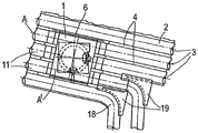
도 2 는 도 1 의 단면의 측면도이다.
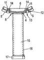
도 3 의 (a) 는 도 1 의 열 교환 표면의 충격 블럭의 평면도이다.
도 3 의 (b) 는 도 3 의 (a) 의 블럭의 측면도이다.
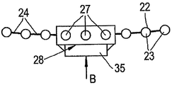
도 4a 는 본 발명에 따른 열 교환 장치의 대안적인 실시형태의 충격 블럭을 갖는 열 교환 표면의 일부의 정면도이다.
도 4b 는 도 4a 의 단면의 평면도이다.
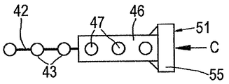
도 5a 는 본 발명에 따른 열 교환 장치의 다른 대안적인 실시형태의 충격 블럭을 갖는 열 교환 표면의 일부의 정면도이다.
도 5b 는 도 5a 의 단면의 평면도이다.
Claims (10)
- 적어도 하나의 열 교환 표면 (2) 을 포함하는 열 교환 장치로서, 상기 열 교환 표면은 하나 이상의 나란한 튜브형 라인 (3), 래퍼 장치 그리고 래퍼 장치를 위한 충격 영역을 포함하고, 상기 충격 영역은 냉매가 통하여 흐르는 하나 이상의 내부 채널 (7) 을 갖는 충격 블럭 (6) 을 포함하고, 각각의 내부 채널은 열 교환 표면의 차단된 튜브형 라인의 대향하는 개방 단부 (5) 를 가교하는 열 교환 장치.
- 제 1 항에 있어서, 상기 튜브형 라인 (3) 은 코일형인 열 교환 장치.
- 제 2 항에 있어서, 전이적 쐐기형 튜브 부분 (11) 이 충격 블럭 (6) 의 내부 채널 (7) 을 차단된 코일형 튜브 (3) 의 대응하는 단부 (5) 에 각각 연결하는 열 교환 장치.
- 제 3 항에 있어서, 상기 전이적 쐐기형 튜브 부분 (11) 과 충격 블럭 (6) 사이의 접촉면은 충격 블럭의 편평한 외부 표면 (8) 에 수직인 열 교환 장치.
- 제 1 항 내지 제 4 항 중 어느 한 항에 있어서, 상기 충격 블럭 (6) 에는 2 개, 3 개 또는 4 개의 내부 채널 (7) 이 삽입되는 열 교환 장치.
- 제 1 항 내지 제 5 항 중 어느 한 항에 있어서, 상기 충격 블럭 (6) 은 앤빌 (15) 을 수반하는 열 교환 장치.
- 제 1 항 내지 제 6 항 중 어느 한 항에 있어서, 상기 열 교환 표면의 단부에서 각각의 코일형 튜브 (3) 는 대응하는 열 교환 표면 (2) 으로부터 분기하고 인접한 코일형 튜브로부터 구부러지며, 보강 웨브 (19) 가 굽힘 부분 (18) 과 인접한 코일형 튜브 (3) 사이에 뻗어있는 열 교환 장치.
- 제 1 항에 있어서, 상기 열 교환 장치는 편평한 열 교환 표면을 형성하는 직선의 튜브형 라인을 포함하는 열 교환 장치.
- 제 8 항에 있어서, 상기 충격 블럭은 열 교환 표면의 측면 중 하나에 위치되는 열 교환 장치.
- 제 9 항에 있어서, 상기 충격 블럭은 그의 측면에 열 교환 표면과 직각 하에 충격 영역을 형성하는 앤빌 판을 수반하는 열 교환 장치.
Applications Claiming Priority (2)
| Application Number | Priority Date | Filing Date | Title |
|---|---|---|---|
| EP09165014.3 | 2009-07-09 | ||
| EP09165014 | 2009-07-09 |
Publications (1)
| Publication Number | Publication Date |
|---|---|
| KR20120042832A true KR20120042832A (ko) | 2012-05-03 |
Family
ID=41651345
Family Applications (1)
| Application Number | Title | Priority Date | Filing Date |
|---|---|---|---|
| KR1020127000482A Ceased KR20120042832A (ko) | 2009-07-09 | 2010-07-06 | 열 교환기 |
Country Status (8)
| Country | Link |
|---|---|
| US (1) | US20120138277A1 (ko) |
| EP (1) | EP2452146B1 (ko) |
| JP (1) | JP2012533043A (ko) |
| KR (1) | KR20120042832A (ko) |
| CN (1) | CN102472592B (ko) |
| AU (1) | AU2010270298B2 (ko) |
| WO (1) | WO2011003890A1 (ko) |
| ZA (1) | ZA201109269B (ko) |
Families Citing this family (1)
| Publication number | Priority date | Publication date | Assignee | Title |
|---|---|---|---|---|
| DE102015010307B4 (de) | 2015-08-07 | 2019-01-10 | Steinmüller Babcock Environment Gmbh | Vorrichtung zur Einleitung von Schlagkräften in eine Heizfläche und Verfahren zum Montieren eines Ambosses |
Family Cites Families (14)
| Publication number | Priority date | Publication date | Assignee | Title |
|---|---|---|---|---|
| US2983994A (en) * | 1955-08-01 | 1961-05-16 | Olin Mathieson | Metal articles having hollow sections and method of making same |
| US2969956A (en) * | 1955-12-27 | 1961-01-31 | Licencia Talalmanyokat | Pipe joint for heat exchange devices |
| US3417419A (en) * | 1965-10-08 | 1968-12-24 | Zaklady Energetyczne Okregu Po | Device for removing slag from heating surfaces of waterwall tubes in the boiler |
| FI52147C (fi) * | 1971-08-19 | 1977-06-10 | Ahlstroem Oy | Menetelmä ja laite höyrykattilan putkiston ulkopuolista puhdistusta va rten |
| DE3127734C1 (de) | 1981-07-14 | 1983-04-21 | L. & C. Steinmüller GmbH, 5270 Gummersbach | Verbindungselement zum UEbertragen der Klopf- oder Schlagenergie auf in einem Druckbehaelter befindliche,zu reinigende Heiz- oder Kuehlflaechen |
| US4497282A (en) * | 1983-11-23 | 1985-02-05 | Neundorfer, Inc. | Apparatus for deslagging steam generator tubes |
| US4741292A (en) * | 1986-12-22 | 1988-05-03 | The Babcock & Wilcox Company | Electro-impulse rapper system for boilers |
| DE3725424C1 (de) * | 1987-07-31 | 1988-07-21 | Steinmueller Gmbh L & C | Strahlungskuehler fuer die Abkuehlung von mit Staub beladenen Gasen |
| DE4324586C1 (de) * | 1993-07-22 | 1994-11-17 | Steinmueller Gmbh L & C | Vorrichtung zum Abkühlen eines belagbildenden Gases |
| US5429077A (en) * | 1994-07-15 | 1995-07-04 | The Babcock & Wilcox Company | Water hammer rapper method and apparatus |
| DE19810733A1 (de) * | 1998-03-12 | 1999-09-16 | Oschatz Gmbh | Vorrichtung zum Reinigen einer Kesselrohrwand |
| JP2000035176A (ja) * | 1998-07-21 | 2000-02-02 | Misawa Hoobasu Kk | 配管用継手 |
| LU90328B1 (de) * | 1998-12-16 | 2003-06-26 | Paul Wutrh S A | Kuehlplatte fuer einen Ofen zur Eisen- oder Stahlerzeugung |
| CN2632619Y (zh) * | 2003-08-08 | 2004-08-11 | 北京恩菲科技产业集团 | 弹性锤击式振打装置 |
-
2010
- 2010-07-06 US US13/382,326 patent/US20120138277A1/en not_active Abandoned
- 2010-07-06 EP EP10731507.9A patent/EP2452146B1/en active Active
- 2010-07-06 WO PCT/EP2010/059610 patent/WO2011003890A1/en not_active Ceased
- 2010-07-06 CN CN201080030682.0A patent/CN102472592B/zh active Active
- 2010-07-06 AU AU2010270298A patent/AU2010270298B2/en active Active
- 2010-07-06 JP JP2012518960A patent/JP2012533043A/ja active Pending
- 2010-07-06 KR KR1020127000482A patent/KR20120042832A/ko not_active Ceased
-
2011
- 2011-12-15 ZA ZA2011/09269A patent/ZA201109269B/en unknown
Also Published As
| Publication number | Publication date |
|---|---|
| EP2452146A1 (en) | 2012-05-16 |
| WO2011003890A1 (en) | 2011-01-13 |
| AU2010270298B2 (en) | 2013-11-14 |
| EP2452146B1 (en) | 2013-04-24 |
| AU2010270298A1 (en) | 2012-01-19 |
| US20120138277A1 (en) | 2012-06-07 |
| ZA201109269B (en) | 2012-09-26 |
| JP2012533043A (ja) | 2012-12-20 |
| CN102472592B (zh) | 2015-03-25 |
| CN102472592A (zh) | 2012-05-23 |
Similar Documents
| Publication | Publication Date | Title |
|---|---|---|
| KR101656907B1 (ko) | 모듈형 플레이트 및 쉘 열교환기 | |
| CN101644369A (zh) | 反应管和冷却管之间的连接器以及将反应管连接到冷却管的方法 | |
| GB2588728A (en) | Ribbed tubeless heat exchanger for fliud heating systems including a rib component and methods of manufacture thereof | |
| CN101975527B (zh) | 一种线性急冷换热器入口连接件及其急冷换热器 | |
| CA2708055C (en) | Heat exchanger for cooling reaction gas, including a tubular connection between a cooled tube and an uncooled tube | |
| ES2961914T3 (es) | Intercambiador de calor de doble tubo y método de fabricación del mismo | |
| CN101122451B (zh) | 锅炉管壁 | |
| CN201032440Y (zh) | 蛇形结构分离式热管换热系统 | |
| EP1722181B1 (en) | Connection between cooled pipe and uncooled pipe in a double-pipe heat exchanger | |
| EP2452146B1 (en) | Heat exchanger | |
| JP6150380B2 (ja) | 熱交換器及び熱交換器の製造方法 | |
| CN203464830U (zh) | 一种换热器换热管与管板的连接结构 | |
| CN202229161U (zh) | 余热锅炉管束 | |
| CN201068433Y (zh) | 一种急冷锅炉 | |
| CN210398879U (zh) | 锅炉尾部受热面防磨机构 | |
| BRPI0405656B1 (pt) | Método de conexão de tubo de transferência de calor e tubo capilar | |
| CN201852516U (zh) | 一种线性急冷换热器入口连接件及其急冷换热器 | |
| US20120125567A1 (en) | Heat exchanger | |
| CN214536151U (zh) | 一种用于循环流化床锅炉的喷嘴组送风装置 | |
| CN113340130A (zh) | 一种内置膨胀节的单管程式换热器及其制造方法 | |
| CN218096025U (zh) | 一种锅炉耐磨水冷壁 | |
| CN219037679U (zh) | 烟气取热器 | |
| CN121297513A (zh) | 一种新型内孔焊插花式换热器 | |
| CN203908384U (zh) | 一种线性急冷换热器入口连接件 | |
| JPS5813987A (ja) | 伝熱装置 |
Legal Events
| Date | Code | Title | Description |
|---|---|---|---|
| PA0105 | International application |
Patent event date: 20120106 Patent event code: PA01051R01D Comment text: International Patent Application |
|
| PG1501 | Laying open of application | ||
| A201 | Request for examination | ||
| PA0201 | Request for examination |
Patent event code: PA02012R01D Patent event date: 20150701 Comment text: Request for Examination of Application |
|
| E902 | Notification of reason for refusal | ||
| PE0902 | Notice of grounds for rejection |
Comment text: Notification of reason for refusal Patent event date: 20160629 Patent event code: PE09021S01D |
|
| AMND | Amendment | ||
| E601 | Decision to refuse application | ||
| PE0601 | Decision on rejection of patent |
Patent event date: 20161228 Comment text: Decision to Refuse Application Patent event code: PE06012S01D Patent event date: 20160629 Comment text: Notification of reason for refusal Patent event code: PE06011S01I |
|
| AMND | Amendment | ||
| PX0901 | Re-examination |
Patent event code: PX09011S01I Patent event date: 20161228 Comment text: Decision to Refuse Application Patent event code: PX09012R01I Patent event date: 20160829 Comment text: Amendment to Specification, etc. |
|
| PX0601 | Decision of rejection after re-examination |
Comment text: Decision to Refuse Application Patent event code: PX06014S01D Patent event date: 20170428 Comment text: Amendment to Specification, etc. Patent event code: PX06012R01I Patent event date: 20170328 Comment text: Decision to Refuse Application Patent event code: PX06011S01I Patent event date: 20161228 Comment text: Amendment to Specification, etc. Patent event code: PX06012R01I Patent event date: 20160829 Comment text: Notification of reason for refusal Patent event code: PX06013S01I Patent event date: 20160629 |