KR20120054792A - Upper rail for sliding door - Google Patents
Upper rail for sliding door Download PDFInfo
- Publication number
- KR20120054792A KR20120054792A KR1020100116094A KR20100116094A KR20120054792A KR 20120054792 A KR20120054792 A KR 20120054792A KR 1020100116094 A KR1020100116094 A KR 1020100116094A KR 20100116094 A KR20100116094 A KR 20100116094A KR 20120054792 A KR20120054792 A KR 20120054792A
- Authority
- KR
- South Korea
- Prior art keywords
- sliding door
- chain
- upper rail
- lower support
- support piece
- Prior art date
- Legal status (The legal status is an assumption and is not a legal conclusion. Google has not performed a legal analysis and makes no representation as to the accuracy of the status listed.)
- Granted
Links
Images



Classifications
-
- E—FIXED CONSTRUCTIONS
- E05—LOCKS; KEYS; WINDOW OR DOOR FITTINGS; SAFES
- E05F—DEVICES FOR MOVING WINGS INTO OPEN OR CLOSED POSITION; CHECKS FOR WINGS; WING FITTINGS NOT OTHERWISE PROVIDED FOR, CONCERNED WITH THE FUNCTIONING OF THE WING
- E05F15/00—Power-operated mechanisms for wings
- E05F15/60—Power-operated mechanisms for wings using electrical actuators
- E05F15/603—Power-operated mechanisms for wings using electrical actuators using rotary electromotors
- E05F15/632—Power-operated mechanisms for wings using electrical actuators using rotary electromotors for horizontally-sliding wings
- E05F15/643—Power-operated mechanisms for wings using electrical actuators using rotary electromotors for horizontally-sliding wings operated by flexible elongated pulling elements, e.g. belts, chains or cables
-
- E—FIXED CONSTRUCTIONS
- E05—LOCKS; KEYS; WINDOW OR DOOR FITTINGS; SAFES
- E05D—HINGES OR SUSPENSION DEVICES FOR DOORS, WINDOWS OR WINGS
- E05D15/00—Suspension arrangements for wings
- E05D15/06—Suspension arrangements for wings for wings sliding horizontally more or less in their own plane
- E05D15/0621—Details, e.g. suspension or supporting guides
- E05D15/0626—Details, e.g. suspension or supporting guides for wings suspended at the top
- E05D15/063—Details, e.g. suspension or supporting guides for wings suspended at the top on wheels with fixed axis
-
- E—FIXED CONSTRUCTIONS
- E06—DOORS, WINDOWS, SHUTTERS, OR ROLLER BLINDS IN GENERAL; LADDERS
- E06B—FIXED OR MOVABLE CLOSURES FOR OPENINGS IN BUILDINGS, VEHICLES, FENCES OR LIKE ENCLOSURES IN GENERAL, e.g. DOORS, WINDOWS, BLINDS, GATES
- E06B3/00—Window sashes, door leaves, or like elements for closing wall or like openings; Layout of fixed or moving closures, e.g. windows in wall or like openings; Features of rigidly-mounted outer frames relating to the mounting of wing frames
- E06B3/32—Arrangements of wings characterised by the manner of movement; Arrangements of movable wings in openings; Features of wings or frames relating solely to the manner of movement of the wing
- E06B3/34—Arrangements of wings characterised by the manner of movement; Arrangements of movable wings in openings; Features of wings or frames relating solely to the manner of movement of the wing with only one kind of movement
- E06B3/42—Sliding wings; Details of frames with respect to guiding
- E06B3/46—Horizontally-sliding wings
- E06B3/4636—Horizontally-sliding wings for doors
-
- E—FIXED CONSTRUCTIONS
- E05—LOCKS; KEYS; WINDOW OR DOOR FITTINGS; SAFES
- E05Y—INDEXING SCHEME ASSOCIATED WITH SUBCLASSES E05D AND E05F, RELATING TO CONSTRUCTION ELEMENTS, ELECTRIC CONTROL, POWER SUPPLY, POWER SIGNAL OR TRANSMISSION, USER INTERFACES, MOUNTING OR COUPLING, DETAILS, ACCESSORIES, AUXILIARY OPERATIONS NOT OTHERWISE PROVIDED FOR, APPLICATION THEREOF
- E05Y2201/00—Constructional elements; Accessories therefor
- E05Y2201/60—Suspension or transmission members; Accessories therefor
- E05Y2201/622—Suspension or transmission members elements
- E05Y2201/644—Flexible elongated pulling elements
- E05Y2201/656—Chains
-
- E—FIXED CONSTRUCTIONS
- E05—LOCKS; KEYS; WINDOW OR DOOR FITTINGS; SAFES
- E05Y—INDEXING SCHEME ASSOCIATED WITH SUBCLASSES E05D AND E05F, RELATING TO CONSTRUCTION ELEMENTS, ELECTRIC CONTROL, POWER SUPPLY, POWER SIGNAL OR TRANSMISSION, USER INTERFACES, MOUNTING OR COUPLING, DETAILS, ACCESSORIES, AUXILIARY OPERATIONS NOT OTHERWISE PROVIDED FOR, APPLICATION THEREOF
- E05Y2201/00—Constructional elements; Accessories therefor
- E05Y2201/60—Suspension or transmission members; Accessories therefor
- E05Y2201/622—Suspension or transmission members elements
- E05Y2201/684—Rails; Tracks
Landscapes
- Engineering & Computer Science (AREA)
- Mechanical Engineering (AREA)
- Civil Engineering (AREA)
- Structural Engineering (AREA)
- Closing And Opening Devices For Wings, And Checks For Wings (AREA)
Abstract
본 발명은 각종 건물이나 시설물의 출입구에 설치사용되는 슬라이딩 도어를 구성하되, 구동모터의 작동에 의해 체인이 회전하면서 슬라이딩 도어를 개폐작동케 하고, 슬라이딩 도어를 지지하면서 주행롤러가 주행하는 상부레일에 체인의 처짐방지수단을 구비하여, 슬라이딩 도어의 개페작동을 위한 체인의 처짐현상을 방지케 하고, 상기 처짐방지수단에는 소음방지수단을 함께 구비하여 슬라이딩 도어의 개폐가 정숙한 상태에서 원활한 주행이 이루어질 수 있게 한 것이다.
상기 과제를 해결하기 위한 수단으로서, 본 발명은 슬라이딩 도어를 지지하면서 개폐시 주행을 안내하는 슬라이딩 도어 상부레일을 구성함에 있어서, 상부레일을 구성하는 본체의 측판에 다수개의 요철부를 구성하고, 상기 측판 내측에 수지받침대가 끼워진 상부지지편과 하부지지편을 구성하고, 하부지지편 하단에는 가이드편을 구성하여 안내홈이 형성되게 함으로서, 가이드바에 구성된 안내홈에 슬라이딩 도어 상단에 연결된 주행롤러가 주행되게 하고, 상하부 지지편에 끼워진 수지받침대 상에 구동모터에 의해 좌우회전하는 체인이 안치되게 하여 체인의 처짐을 방지케 한 것이다.The present invention constitutes a sliding door that is used to be installed at the entrance and exit of various buildings or facilities, the chain is rotated by the operation of the drive motor to open and close the sliding door, and to support the sliding door to the upper rail running roller running It is provided with a deflection prevention means of the chain, to prevent the deflection of the chain for opening and closing the sliding door, and the deflection prevention means is provided with a noise prevention means for smooth running in the state of opening and closing the sliding door quietly. It was made possible.
As a means for solving the above problems, the present invention comprises a plurality of uneven parts in the side plate of the main body constituting the upper rail in configuring a sliding door upper rail for guiding driving during opening and closing while supporting the sliding door, The upper support piece and the lower support piece in which the resin support is fitted are formed on the inner side, and the guide piece is formed on the lower part of the lower support piece so that the guide groove is formed. In addition, the chain rotated left and right by the driving motor on the resin supporter fitted to the upper and lower support pieces to prevent the chain from sagging.

Description
본 발명은 슬라이딩 도어(행거 도어)용 상부레일의 개량에 관한 것으로서, 특히 레일 상에 체인의 처짐방지 및 소음방지수단을 구비하여 슬라이딩 도어의 원활한 개폐작동이 이루어질 수 있게 한 것이다.The present invention relates to an improvement of an upper rail for a sliding door (hanger door), and in particular, to prevent the sagging of the chain and noise prevention means on the rail, so that the smooth opening and closing operation of the sliding door can be made.
일반적으로 행거도어, 즉 슬라이딩 도어는 각종 건물이나 시설물의 자동문으로 설치되는 것으로서, 상하레일이 형성된 사각틀 형상의 프레임 내측에 슬라이딩 도어가 설치되고, 상기 슬라이딩 도어가 상하레일을 따라 미닫이방식으로 개폐되도록 구성하되, 상기 슬라이딩 도어 상하부에 각각 다수개의 롤러가 설치되어 있어, 프레임을 구성하는 상하레일 위를 주행케 함으로서 슬라이딩 도어가 원활한 개폐가 이루어질 수 있게 한다.In general, a hanger door, that is, a sliding door is installed as an automatic door of various buildings or facilities, and a sliding door is installed inside a frame having a rectangular frame having upper and lower rails, and the sliding door is configured to be opened and closed along the upper and lower rails in a sliding manner. However, each of the plurality of rollers are installed on the upper and lower portions of the sliding door, so that the sliding door can be smoothly opened and closed by running on the upper and lower rails constituting the frame.
이때 슬라이딩 도어의 개폐수단은 통상적으로 상부레일 양측 단부에 구동모터에 의해 회전하는 스프로켓을 설치하여 체인으로 연결하고, 상기 체인에 슬라이딩 도어를 연결하여 구동모터에 의해 체인이 회전하면 체인과 연결된 슬라이딩 도어가 좌우로 이동하면서 개폐되게 한 것이다.At this time, the opening and closing means of the sliding door is typically connected to the chain by installing a sprocket that is rotated by the driving motor at both ends of the upper rail, and the sliding door is connected to the chain by connecting the sliding door to the chain and the chain is rotated by the driving motor. Will move left and right while moving left and right.
상기에서 양측 스프로켓 사이를 연결하는 체인은 팽팽하게 긴장된 상태를 유지하는 것이 바람직하며, 이를 위하여 일측 스프로켓에 체인장력조정장치를 설치하여 긴장력이 부여되게 하고 있으나 체인의 길이가 길거나, 사용으로 인하여 이완이 되면 체인의 처짐은 불가피하게 되므로 슬라이딩 도어의 원활한 주행 및 정확한 개폐작동에 장애의 요인이 된다.The chain connecting the two sprockets in the above is preferably maintained in a tensioned state, for this purpose, the chain tension adjusting device is installed on one side of the sprocket to give a tension force, but the length of the chain is loose or loose due to use If the chain sag is inevitable, it becomes a obstacle to smooth running and accurate opening and closing operation of the sliding door.
따라서 체인의 처짐을 방지하기 위하여 주기적으로 장력조정장치를 이용하여 체인을 긴장된 상태로 팽팽하게 조정하여야 하는 관리상의 어려움이 있을 뿐 아니라 이러한 경우 구동모터에도 과중한 긴장력이 부여되어 원활한 작동에 방해의 요인이 되는 등의 단점이 있는 것이었다.Therefore, in order to prevent the chain from sagging, there is a management difficulty in that the chain is tensioned in a tensioned state by using a tension adjusting device periodically. In this case, too much tension is applied to the driving motor, which causes a disturbance in smooth operation. There was a disadvantage such as being.
본 발명은 이러한 종래의 제반 단점을 시정하고자 각종 건물이나 시설물의 출입구에 설치사용되는 슬라이딩 도어를 구성하되, 구동모터의 작동에 의해 체인이 회전하면서 슬라이딩 도어를 개폐작동케 하고, 슬라이딩 도어를 지지하면서 주행롤러가 주행하는 상부레일에 체인의 처짐방지수단을 구비하여, 슬라이딩 도어의 개페작동을 위한 체인의 처짐현상을 방지케 하고, 상기 처짐방지수단에는 소음방지수단을 함께 구비하여 슬라이딩 도어의 개폐가 정숙한 상태에서 원활한 작동이 이루어질 수 있게 한 것이다.The present invention constitutes a sliding door that is used to be installed at the entrance and exit of various buildings or facilities in order to correct the various disadvantages of the conventional, while opening and closing the sliding door while the chain rotates by the operation of the drive motor, while supporting the sliding door. The upper rail on which the traveling roller travels is provided with a deflection prevention means of the chain to prevent the deflection of the chain for opening and closing the sliding door, and the deflection prevention means is provided with a noise prevention means to open and close the sliding door. Smooth operation is achieved in a quiet state.
상기 과제를 해결하기 위한 수단으로서, 본 발명은 슬라이딩 도어를 지지하면서 개폐시 주행을 안내하는 슬라이딩 도어 상부레일을 구성함에 있어서, 상부레일을 구성하는 본체의 측판에 다수개의 요철부를 구성하고, 상기 측판 내측에 수지받침대가 끼워진 상부지지편과 하부지지편을 구성하고, 하부지지편 하단에는 가이드편을 구성하여 안내홈이 형성되게 함으로서, 가이드바에 구성된 안내홈에 슬라이딩 도어 상단에 연결된 주행롤러가 주행되게 하고, 상하부 지지편에 끼워진 수지받침대 상에 구동모터에 의해 좌우회전하는 체인이 안치되게 하여 체인의 처짐을 방지케 한 것이다.As a means for solving the above problems, the present invention comprises a plurality of uneven parts in the side plate of the main body constituting the upper rail in configuring a sliding door upper rail for guiding driving during opening and closing while supporting the sliding door, The upper support piece and the lower support piece in which the resin support is fitted are formed on the inner side, and the guide piece is formed on the lower part of the lower support piece so that the guide groove is formed. In addition, the chain rotated left and right by the driving motor on the resin supporter fitted to the upper and lower support pieces to prevent the chain from sagging.
본 발명은 슬라이딩 도어(행거 도어)를 지지하면서 주행을 안내하는 상부레일을 구성함에 있어서, 상부레일을 구성하는 본체 일측에 상하부 지지바를 구성하고, 상기 상하부 지지편 상에 수지받침대를 끼워 구성케 함으로서, 구동모터의 작동에 의해 좌우이동하는 체인이 상하부 지지편에 끼워진 수지받침대 상에 안치된 상태에서 좌우이동되게 하여, 체인의 처짐을 방지할 수 있게 함과 동시에 소음발생을 억제케 하여 정숙한 상태에서 슬라이딩 도어의 원활한 주행이 이루어질 수 있게 되는 등의 효과가 있는 것이다.The present invention is to configure the upper rail for guiding the running while supporting the sliding door (hanger door), by configuring the upper and lower support bar on one side of the main body constituting the upper rail, by putting the resin support on the upper and lower support pieces In addition, the chain moving left and right by the operation of the drive motor is moved left and right in a state where it is placed on the resin support inserted in the upper and lower support pieces, thereby preventing the chain from sagging and at the same time quieting the noise. In the effect that the smooth running of the sliding door can be made.
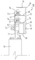
도 1 : 본 발명에서 제공하고자 하는 슬라이딩 도어용 상부레일
도 2 : 본 발명에서 제공하고자 하는 슬라이딩 도어용 상부레일의 측면구성도
도 3 : 본 발명의 사용상태 정면개략구성도
도 4 : 도 3의 구동모터부분의 개략구성도
도 5 : 도 3의 슬라이딩 도어와 체인결합부의 개략구성도
도 6 : 도 3의 피동스프로켓 부분의 개략구성도
도 7 : 본 발명의 사용상태도로서 구동스프로켓 부분의 사시도
도 8 : 도 5의 사시도
도 9 : 본 발명의 사용상태 측면구성도
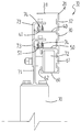
도 10 : 본 발명의 사용상태 측면구성도로서 다른 예시도
도 11 : 도 10에 사용되는 수지받침대의 구성도1: Upper rail for sliding door to be provided in the present invention
2 is a side configuration diagram of the upper rail for a sliding door to be provided in the present invention
3 is a schematic front view of a state of use of the present invention
4 is a schematic configuration diagram of a driving motor part of FIG.
5: Schematic configuration diagram of the sliding door and the chain coupling portion of FIG.
6 is a schematic configuration diagram of a driven sprocket portion of FIG.
7 is a perspective view of a driving sprocket as a state diagram of use of the present invention;
8: perspective view of FIG. 5
9 is a side configuration diagram of the use state of the present invention
Figure 10 is another exemplary view as a side view of the use state of the present invention
11 is a block diagram of the resin support used in FIG.
이하 본 발명의 실시예를 첨부도면에 따라 상세히 설명하면 다음과 같다.Hereinafter, embodiments of the present invention will be described in detail with reference to the accompanying drawings.
도 1은 본 발명에서 제공하고자 하는 슬라이딩 도어용 상부레일(10)의 사시도이고, 도 2는 측면구성도이고, 도 3 내지 도 9는 사용상태의 각부 확대상태도이다.1 is a perspective view of an
즉 상부레일(10)을 구성하는 본체(20)의 측판(30) 일측에 상부지지바(40)와 하부지지바(50)를 구성하고, 측판(30) 하단에는 가이드편(60)을 구성하여 안내홈(61)이 형성되게 한다.That is, the
측판(20) 상부에는 상판(31)이 구성되게 하고, 측판(20) 자체에는 요철부(32)를 구성하여 휨과 비틀림강도를 보강케 함과 동시에 요철부(32)에 직결피스나 볼트머리부나 너트가 매립형으로 위치되게 한다.The
상하부 지지편(40)(50)은 상부레일(10)의 사용시 체인이 위치되게 하여 처짐을 방지하는 기능을 하는 것으로서, 상하부 지지편(40)(50)만으로도 사용이 가능하나, 상하부 지지편(40)(50) 상에 합성수지로 구성된 수지받침대(41)(51)를 구성하여, 체인과 접촉시 소음발생없이 정숙한 이동이 이루어질 수 있게 하는 것이 바람직하다.The upper and
상기 수지받침대(41)(51)의 결합수단은 상하부 지지편(40)(50) 상에 삽입홈(42)(52)이 형성된 걸림돌부(43)(53)를 구성하고, 상기 삽입홈(42)(52)에 평판형의 수지받침대(41)(51)를 분해조립식으로 결합한다.Coupling means of the resin support (41) (51) constitutes the engaging protrusions (43) (53) formed with insertion grooves (42) (52) on the upper and lower support pieces (40) (50), and the insertion groove ( 42) to 52 are assembled to disassemble and assembled a flat resin support (41) (51).
상기 상하부 지지편(40)(50)에 구성되는 수지받침대(41)(51)는 도 11에서와 같이 밑판(41-1)(51-1)과 측판(41-2)(51-2)으로 구성된 C형의 수지받침대(41)(51)를 사용할 수도 있다.As shown in FIG. 11, the
측판(30) 하단에 구성되는 가이드편(60) 단부와 하부지지편(50) 아랫쪽에는 절곡부(62)를 구성하여 안내홈(61)에 끼워지는 주행롤러의 이탈이 방지될 수 있게 한다.The lower end of the
미설명부호 (70)은 슬라이딩 도어, (71)은 연결브라켓, (72)는 주행롤러, (73)은 연결편, (74)는 체인, (75)는 구동스프로켓이다.
이와 같이 구성된 본 발명의 상부레일(10)은 도 3 내지 도 9에서와 같이 건물이나 각종 시설물의 출입구에 설치하여 사용하는 자동슬라이딩도어(70)의 개폐작동시 슬라이딩 도어(70)에 구성된 주행롤러(72)가 상부레일(10)의 안내홈(61)에 끼워져 주행케 하고, 구동모터(M)의 작동에 의해 체인(73)이 정역회전하면서 체인(73)과 연결된 슬라이딩 도어(70)가 개폐되게 한다는 것은 종래와 같다.The
그러나 본 발명에서 제공하고자 하는 슬라이딩 도어용 상부레일(10)은 구동모터(M)에 의해 정역회전하는 체인(74)이 상부지지편(40)과 하부지지편(50)에 의해 지지되므로 종래와 같이 사용중 체인(73)의 처짐현상이 발생하지 않게 된다.However, the
특히 상하부 지지편(40)(50) 상면, 즉 체인(74)과 접촉하는 부위에는 수지받침대(41)(51)가 끼워져 있고, 상기 수지받침대(41)(51) 상에 체인(74)이 접촉하게 되므로 소음발생없이 정숙한 상태로 체인(74)이 이동하게 된다.In particular, the
상기에서 사용되는 수지받침대(41)(51)는 도 10 및 도 11에서와 같이 밑판(41-1)(51-1)과 측판(41-2)(51-2)으로 구성된 수지받침대(41)(51)를 사용할 수도 있다.The
측판(30)에 구성된 요철부(32)는 상부레일(10)의 길이가 길어지게 되더라도 비틀림 및 휨에 대한 강성을 보강케 할 뿐 아니라 직결피스나 볼ㅌ, 너트의 머리부가 매립위치되게 하는 기능도 하게 된다.The concave-
사용중 상하부 지지편(40)(50)에 끼워진 수지받침대(41)(51)의 마모시에는 걸림돌부(43)(53)의 삽입홈(42)(52)으로부터 수지받침대(41)(51)를 분리시킨 다음 새로운 수지받침대(41)(51)를 교체하면 된다.When the
(10)--상부레일 (20)--본체
(30)--측판 (31)--상판
(32)--요철부 (40)--상부지지편
(41)--수지받침대 (42)--삽입홈
(43)--걸림돌부 (50)--하부지지편
(51)--수지받침대 (52)--삽입홈
(53)--걸림돌부 (60)--가이드편
(61)--안내홈 (62)--절곡부(10)-Upper Rail (20)-Body
(30)-side plate (31)-top plate
(32)-Uneven (40)-Upper Support
(41)-resin support (42)-insertion groove
(43)-Jangbu (50)-Lower Support
(51)-resin support (52)-insertion groove
(53)-Jangbu (60)-Guide
(61)-Guide Groove (62)-Bending
Claims (4)
Priority Applications (1)
| Application Number | Priority Date | Filing Date | Title |
|---|---|---|---|
| KR1020100116094A KR101248590B1 (en) | 2010-11-22 | 2010-11-22 | Upper rail for sliding door |
Applications Claiming Priority (1)
| Application Number | Priority Date | Filing Date | Title |
|---|---|---|---|
| KR1020100116094A KR101248590B1 (en) | 2010-11-22 | 2010-11-22 | Upper rail for sliding door |
Publications (2)
| Publication Number | Publication Date |
|---|---|
| KR20120054792A true KR20120054792A (en) | 2012-05-31 |
| KR101248590B1 KR101248590B1 (en) | 2013-03-28 |
Family
ID=46270485
Family Applications (1)
| Application Number | Title | Priority Date | Filing Date |
|---|---|---|---|
| KR1020100116094A Expired - Fee Related KR101248590B1 (en) | 2010-11-22 | 2010-11-22 | Upper rail for sliding door |
Country Status (1)
| Country | Link |
|---|---|
| KR (1) | KR101248590B1 (en) |
Cited By (1)
| Publication number | Priority date | Publication date | Assignee | Title |
|---|---|---|---|---|
| WO2017156569A1 (en) * | 2016-03-14 | 2017-09-21 | Superlift Garage Door Openers Ltd | A noise dampening device |
Families Citing this family (1)
| Publication number | Priority date | Publication date | Assignee | Title |
|---|---|---|---|---|
| KR102959054B1 (en) * | 2025-05-23 | 2026-04-30 | 탑판넬 주식회사 | Automatic door apparatus for disabled persons |
Family Cites Families (4)
| Publication number | Priority date | Publication date | Assignee | Title |
|---|---|---|---|---|
| KR970001120Y1 (en) * | 1994-09-02 | 1997-02-18 | 아시아자동차공업 주식회사 | Bus lamp frame |
| KR200349638Y1 (en) * | 2004-02-10 | 2004-05-08 | 기 동 조 | A Open and Shut Apparatus for Sliding Door |
| KR200458072Y1 (en) * | 2008-07-22 | 2012-01-18 | (주)애니텍 | Rail plate of automatic door guide rail |
| KR20100102754A (en) * | 2009-03-12 | 2010-09-27 | 장영근 | The guide rail for automatic door |
-
2010
- 2010-11-22 KR KR1020100116094A patent/KR101248590B1/en not_active Expired - Fee Related
Cited By (1)
| Publication number | Priority date | Publication date | Assignee | Title |
|---|---|---|---|---|
| WO2017156569A1 (en) * | 2016-03-14 | 2017-09-21 | Superlift Garage Door Openers Ltd | A noise dampening device |
Also Published As
| Publication number | Publication date |
|---|---|
| KR101248590B1 (en) | 2013-03-28 |
Similar Documents
| Publication | Publication Date | Title |
|---|---|---|
| US7346939B2 (en) | Triple slide frameless shower door | |
| KR101744251B1 (en) | The interlock for the sliding three door | |
| KR20100093265A (en) | A linked opening and closing device for sliding door | |
| KR101248590B1 (en) | Upper rail for sliding door | |
| US9243685B2 (en) | Noise reduction device | |
| KR101234865B1 (en) | A guide rail fixing apparatus for an automatic door | |
| KR20130001596U (en) | 3 Moving device for 3 sliding door | |
| KR100960948B1 (en) | Automatic opening and shutting device for sliding door and sliding door using the same | |
| KR101057296B1 (en) | Sliding connection of semi-automatic retractable door | |
| US4001969A (en) | Garage door structure | |
| AU2012231790B2 (en) | Track radius structure | |
| AU2012231789B2 (en) | Roller assembly | |
| KR102861892B1 (en) | Automatic door opening and closing device | |
| KR101244871B1 (en) | Sliding door | |
| JPH0113187Y2 (en) | ||
| JP3921217B2 (en) | Double sliding door | |
| KR200395108Y1 (en) | The guide-holding structure of equipment open and shut drapes | |
| JPH05559Y2 (en) | ||
| WO2013098716A1 (en) | Supporting frame for sectional doors | |
| KR101431959B1 (en) | Connecting Apparatus for Semiautomatic opening door | |
| TWI895176B (en) | Track assembly structure for flat doors and windows | |
| JPH0113186Y2 (en) | ||
| JPH0715990Y2 (en) | Automatic door | |
| KR200421519Y1 (en) | Guide Rail Support Structure | |
| JP7295730B2 (en) | sliding door device |
Legal Events
| Date | Code | Title | Description |
|---|---|---|---|
| A201 | Request for examination | ||
| PA0109 | Patent application |
St.27 status event code: A-0-1-A10-A12-nap-PA0109 |
|
| PA0201 | Request for examination |
St.27 status event code: A-1-2-D10-D11-exm-PA0201 |
|
| D13-X000 | Search requested |
St.27 status event code: A-1-2-D10-D13-srh-X000 |
|
| D14-X000 | Search report completed |
St.27 status event code: A-1-2-D10-D14-srh-X000 |
|
| PG1501 | Laying open of application |
St.27 status event code: A-1-1-Q10-Q12-nap-PG1501 |
|
| E902 | Notification of reason for refusal | ||
| PE0902 | Notice of grounds for rejection |
St.27 status event code: A-1-2-D10-D21-exm-PE0902 |
|
| E13-X000 | Pre-grant limitation requested |
St.27 status event code: A-2-3-E10-E13-lim-X000 |
|
| P11-X000 | Amendment of application requested |
St.27 status event code: A-2-2-P10-P11-nap-X000 |
|
| P13-X000 | Application amended |
St.27 status event code: A-2-2-P10-P13-nap-X000 |
|
| E701 | Decision to grant or registration of patent right | ||
| PE0701 | Decision of registration |
St.27 status event code: A-1-2-D10-D22-exm-PE0701 |
|
| GRNT | Written decision to grant | ||
| PR0701 | Registration of establishment |
St.27 status event code: A-2-4-F10-F11-exm-PR0701 |
|
| PR1002 | Payment of registration fee |
St.27 status event code: A-2-2-U10-U11-oth-PR1002 Fee payment year number: 1 |
|
| PG1601 | Publication of registration |
St.27 status event code: A-4-4-Q10-Q13-nap-PG1601 |
|
| R18-X000 | Changes to party contact information recorded |
St.27 status event code: A-5-5-R10-R18-oth-X000 |
|
| R18-X000 | Changes to party contact information recorded |
St.27 status event code: A-5-5-R10-R18-oth-X000 |
|
| R18-X000 | Changes to party contact information recorded |
St.27 status event code: A-5-5-R10-R18-oth-X000 |
|
| PN2301 | Change of applicant |
St.27 status event code: A-5-5-R10-R13-asn-PN2301 St.27 status event code: A-5-5-R10-R11-asn-PN2301 |
|
| P14-X000 | Amendment of ip right document requested |
St.27 status event code: A-5-5-P10-P14-nap-X000 |
|
| FPAY | Annual fee payment |
Payment date: 20160121 Year of fee payment: 4 |
|
| PR1001 | Payment of annual fee |
St.27 status event code: A-4-4-U10-U11-oth-PR1001 Fee payment year number: 4 |
|
| P22-X000 | Classification modified |
St.27 status event code: A-4-4-P10-P22-nap-X000 |
|
| PR1001 | Payment of annual fee |
St.27 status event code: A-4-4-U10-U11-oth-PR1001 Fee payment year number: 5 |
|
| FPAY | Annual fee payment |
Payment date: 20180112 Year of fee payment: 6 |
|
| PR1001 | Payment of annual fee |
St.27 status event code: A-4-4-U10-U11-oth-PR1001 Fee payment year number: 6 |
|
| P22-X000 | Classification modified |
St.27 status event code: A-4-4-P10-P22-nap-X000 |
|
| FPAY | Annual fee payment |
Payment date: 20190312 Year of fee payment: 7 |
|
| PR1001 | Payment of annual fee |
St.27 status event code: A-4-4-U10-U11-oth-PR1001 Fee payment year number: 7 |
|
| FPAY | Annual fee payment |
Payment date: 20200122 Year of fee payment: 8 |
|
| PR1001 | Payment of annual fee |
St.27 status event code: A-4-4-U10-U11-oth-PR1001 Fee payment year number: 8 |
|
| R18-X000 | Changes to party contact information recorded |
St.27 status event code: A-5-5-R10-R18-oth-X000 |
|
| PR1001 | Payment of annual fee |
St.27 status event code: A-4-4-U10-U11-oth-PR1001 Fee payment year number: 9 |
|
| R18-X000 | Changes to party contact information recorded |
St.27 status event code: A-5-5-R10-R18-oth-X000 |
|
| PR1001 | Payment of annual fee |
St.27 status event code: A-4-4-U10-U11-oth-PR1001 Fee payment year number: 10 |
|
| PR1001 | Payment of annual fee |
St.27 status event code: A-4-4-U10-U11-oth-PR1001 Fee payment year number: 11 |
|
| PR1001 | Payment of annual fee |
St.27 status event code: A-4-4-U10-U11-oth-PR1001 Fee payment year number: 12 |
|
| PN2301 | Change of applicant |
St.27 status event code: A-5-5-R10-R13-asn-PN2301 St.27 status event code: A-5-5-R10-R11-asn-PN2301 |
|
| PC1903 | Unpaid annual fee |
St.27 status event code: A-4-4-U10-U13-oth-PC1903 Not in force date: 20250323 Payment event data comment text: Termination Category : DEFAULT_OF_REGISTRATION_FEE |
|
| H13 | Ip right lapsed |
Free format text: ST27 STATUS EVENT CODE: N-4-6-H10-H13-OTH-PC1903 (AS PROVIDED BY THE NATIONAL OFFICE); TERMINATION CATEGORY : DEFAULT_OF_REGISTRATION_FEE Effective date: 20250323 |
|
| PC1903 | Unpaid annual fee |
St.27 status event code: N-4-6-H10-H13-oth-PC1903 Ip right cessation event data comment text: Termination Category : DEFAULT_OF_REGISTRATION_FEE Not in force date: 20250323 |