KR20120102012A - Brake drum - Google Patents
Brake drum Download PDFInfo
- Publication number
- KR20120102012A KR20120102012A KR20120022705A KR20120022705A KR20120102012A KR 20120102012 A KR20120102012 A KR 20120102012A KR 20120022705 A KR20120022705 A KR 20120022705A KR 20120022705 A KR20120022705 A KR 20120022705A KR 20120102012 A KR20120102012 A KR 20120102012A
- Authority
- KR
- South Korea
- Prior art keywords
- brake drum
- protrusions
- drum
- brake
- casting
- Prior art date
- Legal status (The legal status is an assumption and is not a legal conclusion. Google has not performed a legal analysis and makes no representation as to the accuracy of the status listed.)
- Granted
Links
Images




Classifications
-
- F—MECHANICAL ENGINEERING; LIGHTING; HEATING; WEAPONS; BLASTING
- F16—ENGINEERING ELEMENTS AND UNITS; GENERAL MEASURES FOR PRODUCING AND MAINTAINING EFFECTIVE FUNCTIONING OF MACHINES OR INSTALLATIONS; THERMAL INSULATION IN GENERAL
- F16D—COUPLINGS FOR TRANSMITTING ROTATION; CLUTCHES; BRAKES
- F16D65/00—Parts or details
- F16D65/02—Braking members; Mounting thereof
- F16D65/10—Drums for externally- or internally-engaging brakes
-
- F—MECHANICAL ENGINEERING; LIGHTING; HEATING; WEAPONS; BLASTING
- F16—ENGINEERING ELEMENTS AND UNITS; GENERAL MEASURES FOR PRODUCING AND MAINTAINING EFFECTIVE FUNCTIONING OF MACHINES OR INSTALLATIONS; THERMAL INSULATION IN GENERAL
- F16D—COUPLINGS FOR TRANSMITTING ROTATION; CLUTCHES; BRAKES
- F16D65/00—Parts or details
- F16D65/78—Features relating to cooling
- F16D65/82—Features relating to cooling for internally-engaging brakes
- F16D65/827—Features relating to cooling for internally-engaging brakes with open cooling system, e.g. cooled by air
-
- F—MECHANICAL ENGINEERING; LIGHTING; HEATING; WEAPONS; BLASTING
- F16—ENGINEERING ELEMENTS AND UNITS; GENERAL MEASURES FOR PRODUCING AND MAINTAINING EFFECTIVE FUNCTIONING OF MACHINES OR INSTALLATIONS; THERMAL INSULATION IN GENERAL
- F16D—COUPLINGS FOR TRANSMITTING ROTATION; CLUTCHES; BRAKES
- F16D2200/00—Materials; Production methods therefor
- F16D2200/0004—Materials; Production methods therefor metallic
-
- F—MECHANICAL ENGINEERING; LIGHTING; HEATING; WEAPONS; BLASTING
- F16—ENGINEERING ELEMENTS AND UNITS; GENERAL MEASURES FOR PRODUCING AND MAINTAINING EFFECTIVE FUNCTIONING OF MACHINES OR INSTALLATIONS; THERMAL INSULATION IN GENERAL
- F16D—COUPLINGS FOR TRANSMITTING ROTATION; CLUTCHES; BRAKES
- F16D2200/00—Materials; Production methods therefor
- F16D2200/0004—Materials; Production methods therefor metallic
- F16D2200/0008—Ferro
- F16D2200/0013—Cast iron
-
- F—MECHANICAL ENGINEERING; LIGHTING; HEATING; WEAPONS; BLASTING
- F16—ENGINEERING ELEMENTS AND UNITS; GENERAL MEASURES FOR PRODUCING AND MAINTAINING EFFECTIVE FUNCTIONING OF MACHINES OR INSTALLATIONS; THERMAL INSULATION IN GENERAL
- F16D—COUPLINGS FOR TRANSMITTING ROTATION; CLUTCHES; BRAKES
- F16D2200/00—Materials; Production methods therefor
- F16D2200/0004—Materials; Production methods therefor metallic
- F16D2200/0008—Ferro
- F16D2200/0021—Steel
-
- F—MECHANICAL ENGINEERING; LIGHTING; HEATING; WEAPONS; BLASTING
- F16—ENGINEERING ELEMENTS AND UNITS; GENERAL MEASURES FOR PRODUCING AND MAINTAINING EFFECTIVE FUNCTIONING OF MACHINES OR INSTALLATIONS; THERMAL INSULATION IN GENERAL
- F16D—COUPLINGS FOR TRANSMITTING ROTATION; CLUTCHES; BRAKES
- F16D2200/00—Materials; Production methods therefor
- F16D2200/0004—Materials; Production methods therefor metallic
- F16D2200/0026—Non-ferro
- F16D2200/003—Light metals, e.g. aluminium
-
- F—MECHANICAL ENGINEERING; LIGHTING; HEATING; WEAPONS; BLASTING
- F16—ENGINEERING ELEMENTS AND UNITS; GENERAL MEASURES FOR PRODUCING AND MAINTAINING EFFECTIVE FUNCTIONING OF MACHINES OR INSTALLATIONS; THERMAL INSULATION IN GENERAL
- F16D—COUPLINGS FOR TRANSMITTING ROTATION; CLUTCHES; BRAKES
- F16D2250/00—Manufacturing; Assembly
- F16D2250/0007—Casting
Landscapes
- Engineering & Computer Science (AREA)
- General Engineering & Computer Science (AREA)
- Mechanical Engineering (AREA)
- Braking Arrangements (AREA)
Abstract
Description
본 발명은 자동차 또는 오토바이의 드럼 브레이크에 사용되는 브레이크 드럼에 관한 것이다.The present invention relates to a brake drum for use in a drum brake of an automobile or a motorcycle.
브레이크 드럼으로서, 예컨대, 일본특허공개공보(A) No. 2004-084889에 도시된 브레이크 드럼이 있다. As the brake drum, for example, Japanese Patent Application Laid-Open No. There is a brake drum shown in 2004-084889.
브레이크의 외주면에 미세 양각형상이 형성되어 표면적을 늘리고 이로써 방열능력을 향상시키고 미세 양각형상으로부터 휠 허브로 브레이크 드럼에서 발생된 열을 효율적으로 전달한다. A fine relief is formed on the outer circumferential surface of the brake to increase the surface area, thereby improving heat dissipation, and efficiently transferring heat generated from the brake drum from the fine relief to the wheel hub.
관련 기술로서, 일본특허공개공보(A) No. 2004-084889가 있다.As a related art, Japanese Patent Laid-Open No. (A) No. 2004-084889.
그러나, 일본특허공개공보(A) No. 2004-084889에 도시된 브레이크 드럼에서, 미세 양각형상은 외주면에 형성되나, 양각형상을 이루기 위해 숏 블라스팅(shot blasting)이 사용되어, 회전방향으로 항력(drag strength)이 충분치 않다. 또한, 직경방향으로의 강도도 충분치 않아, 때로 브레이크 슈와 마찰로 인해 발생된 진동으로 비정상적인 소음이 일어난다.However, Japanese Patent Laid-Open No. (A) No. In the brake drum shown in 2004-084889, fine embossed shapes are formed on the outer circumferential surface, but shot blasting is used to achieve the embossed shape, so that drag strength is not sufficient in the rotational direction. In addition, the strength in the radial direction is not sufficient, and abnormal noise sometimes occurs due to vibration generated due to friction with the brake shoe.
본 발명의 목적은 항력, 직경방향으로 세기 및 강도, 결합력, 및 방열능력이 향상될 수 있는 브레이크 드럼을 제공하는 것이다. It is an object of the present invention to provide a brake drum in which drag, strength and strength in the radial direction, coupling force, and heat dissipation can be improved.
본 발명은 드럼 브레이크에 사용되는 브레이크 드럼으로서, 상기 드럼은 외주면에 복수의 돌출부들을 갖고, 상기 복수의 돌출부들은 브레이크 드럼 주조시 전체적으로 외주면에 형성되고, 상기 돌출부들 중 적어도 일부는 개미허리 형상을 갖는 브레이크 드럼을 제공한다. The present invention is a brake drum for use in a drum brake, the drum has a plurality of protrusions on the outer circumferential surface, the plurality of protrusions are formed on the outer circumferential surface as a whole during the casting of the brake drum, at least some of the protrusions have an ant waist shape Provide brake drums.
돌출부들의 높이는 바람직하게는 0.3 내지 5.0㎜인 한편, 돌출부들의 개수는 5 내지 100/㎠이다.The height of the protrusions is preferably 0.3 to 5.0 mm, while the number of protrusions is 5 to 100 /
브레이크 드럼은 바람직하게는 주철, 주강, 또는 알루미늄 합금에 의해 제조된다.The brake drum is preferably made of cast iron, cast steel, or aluminum alloy.
브레이크 드럼은 바람직하게는 원심주조로 제조된다.The brake drum is preferably produced by centrifugal casting.
브레이크 드럼은 예컨대 알루미늄 합금 또는 마그네슘 합금으로 구성된 부재에 인서트 주조에 의해 부착된다. The brake drum is attached by insert casting to a member made of, for example, an aluminum alloy or a magnesium alloy.
본 발명의 브레이크 드럼에 따르면, 전체 외주면은 복수의 돌출부들을 가져, 항력 및 방열능력이 향상된다. 또한, 직경방향으로 세기 및 경도가 향상되고 비정상적 소음이 줄어든다. 또한, 돌출부들 중 일부 또는 모두를 개미허리 형상의 돌출부들로 만듦으로써, 항력과 결합력이 향상되고 더 얇아질 수 있다. According to the brake drum of the present invention, the entire outer circumferential surface has a plurality of protrusions, so that the drag and heat dissipation ability is improved. In addition, the strength and hardness are improved in the radial direction and abnormal noise is reduced. Also, by making some or all of the protrusions into ant waist shaped protrusions, drag and coupling force can be improved and thinner.
본 발명의 이들 및 다른 목적과 특징들은 첨부도면을 참조로 하기에 제시된 바람직한 실시예들의 설명으로부터 더 명백해진다:
도 1은 본 발명의 실시예의 길이방향 횡단면도이다.
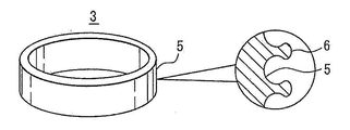
도 2는 브레이크 드럼의 사시도이다.
도 3은 압축 테스트의 개략도이다.
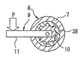
도 4는 항력 테스트의 개략도이다.
도 5는 압축 테스트의 테스트 결과를 도시한 그래프이다.
도 6은 항력 테스트의 테스트 결과를 도시한 그래프이다.These and other objects and features of the present invention will become more apparent from the following description of the preferred embodiments presented below with reference to the accompanying drawings:
1 is a longitudinal cross-sectional view of an embodiment of the invention.
2 is a perspective view of a brake drum.
3 is a schematic diagram of a compression test.
4 is a schematic of a drag test.
5 is a graph showing the test results of the compression test.
6 is a graph showing the test results of the drag test.
하기의 도면을 참조로 본 발명의 바람직한 실시예들을 설명한다. DESCRIPTION OF THE PREFERRED EMBODIMENTS Preferred embodiments of the present invention will be described with reference to the following drawings.
도 1은 브레이크 드럼을 도시한 것이다. 휠(1)의 원주형상의 드럼부(2)의 내주면에, 브레이크 드럼(3)이 인서트 주조로 부착된다. 휠(1)은 알루미늄 합금 또는 마그네슘 합금으로 이루어지는 반면, 브레이크 드럼(3)은 주철, 주강, 또는 알루미늄 합금으로 형성된다. 참조번호 4는 브레이크 드럼(3)의 내주에 대해 가압받는 동작을 갖는 브레이크 슈이다. 1 shows a brake drum. The
원주형상의 브레이크 드럼(3)의 외주면(5)에서(도 2 참조), 복수의 돌출부들(6)이 전체 면적에 걸쳐 형성된다. 이들 돌출부들(6) 가운데, 돌출부들(6) 중 일부 또는 모두는 개미허리 형상을 갖는다. 돌출부(6)의 높이는 0.3 내지 5.0㎜인 한편, 돌출부들(6)의 개수는 5 내지 100/㎠이다.On the outer
돌출부들(6)의 높이가 0.3㎜ 미만이면, 회전방향으로 항력이 불충분해지는 반면, 5.0㎜ 보다 더 크면, 두께 감소 효과를 상실한다. 돌출부들(6)의 개수가 5/㎠ 미만이면, 회전방향으로 항력이 불충분해지는 반면, 100/㎠를 넘으면, 주조능력이 열악해진다. If the height of the
브레이크 드럼(3)은 원심주조로 제조된다. 하기에서, 브레이크 드럼(3)의 제조방법을 설명한다.The
규조토(diatomaceous earth), 벤토나이트(bentonite)(접합제), 물, 및 계면활성제가 몰드와시(mold wash)를 준비하기 위해 기설정된 비율로 혼합된다. 몰드와시는 200에서 400℃로 가열되는 주조성형(성형)의 내부면에 스프레이 코팅되고 회전되어, 이로써 몰드와시층이 주조성형의 내부면에 형성된다. 계면활성제의 작용으로 인해, 복수의 오목 홀들이 몰드와시층의 내부로부터 발생된 가스 버블로 인해 몰드와시층에 형성된다. 몰드와시층은 건조된 후, 용융된 금속이 회전 주조몰드에 부어진다. 이때, 융용된 금속이 몰드와시층의 오목 홀들을 채워 복수의 균일한 돌출부들이 형성된다. 용융된 금속은 브레이크 드럼을 형성하도록 경화된 후 몰드와시층과 함께 주조몰드로부터 브레이크 드럼이 꺼내어 진다. 그런 후, 이는 몰드와시를 제거하기 위해 블라스트되어, 이로써 전체 외주면에 걸쳐 복수의 돌출부들을 갖는 브레이크 드럼이 제조되며, 돌출부들 중 적어도 일부는 개미허리 형상이다.Diatomaceous earth, bentonite (binder), water, and surfactant are mixed in a predetermined ratio to prepare a mold wash. The moldwash is spray coated and rotated on the inner surface of the casting (molding) which is heated from 200 to 400 ° C., thereby forming the mold and the sight layer on the inner surface of the casting. Due to the action of the surfactant, a plurality of concave holes are formed in the mold and the light layer due to the gas bubbles generated from the inside of the mold and the light layer. After the mold-washing layer is dried, molten metal is poured into the rotary casting mold. At this time, the molten metal fills the concave holes of the mold and the viewing layer to form a plurality of uniform protrusions. The molten metal is hardened to form a brake drum and then the brake drum is taken out of the casting mold together with the mold and the layer. It is then blasted to remove the mold and the shi, thereby producing a brake drum having a plurality of protrusions over the entire outer circumferential surface, at least some of which are ant waist shaped.
도 5는 범용 인장/압축 테스트기에 의해 테스트 피스에 압축하중 인가시 하중과 왕복거리(변위) 간의 관계를 도시한 도면이다. 도 3은 압축 테스트의 개략도이다. 알루미늄 합금으로 제조된 원통부재(7)의 내주에서 주철로 제조되며 원통형상을 갖는 브레이크 드럼(3A)을 인서트 주조함으로써 형성된 테스트 피스(8)가 하중 테스트 기계에 의해 위로부터 압축하중(P) 인가시 파열에 이르기까지 변위-하중에 대해 측정된다. 푸싱(pushing) 속도는 3㎜/min이다.FIG. 5 is a diagram showing the relationship between the load and the reciprocating distance (displacement) when compressive load is applied to the test piece by a general purpose tensile / compression tester. 3 is a schematic diagram of a compression test. The test piece 8 formed by insert casting a brake drum 3A made of cast iron and having a cylindrical shape on the inner circumference of the cylindrical member 7 made of aluminum alloy is subjected to a compressive load P from above by a load test machine. Measured for displacement-load up to time rupture. The pushing speed is 3 mm / min.
테스트에 사용된 본 발명의 브레이크 드럼은 돌출부 높이가 0.6에서 0.75㎜이고 돌출부의 개수는 10에서 29/㎠인 반면, 비교예의 브레이크 드럼은 외주면에서 돌출부들로 형성되지 않고, 100에서 250㎛의 표면 거칠기의 양각형상의 최대 높이(Ry)를 가지며, 0.7에서 1.4㎜의 양각형상의 평균거리(Sm)를 갖는다. The brake drum of the present invention used in the test has a protrusion height of 0.6 to 0.75 mm and a number of protrusions of 10 to 29 /
도 5에 도시된 바와 같이, 압축하중은 1.3㎜, 1.8㎜, 및 2.3㎜의 변위의 비교예보다 본 발명에서 약 1.3에서 1.4 배 더 크다. 또한, 파열하중은 본 발명에서 약 19kN이며 비교예에서는 약 12.5kN이다. 본 발명은 파열하중이 비교예보다 약 1.5배 더 크다. As shown in FIG. 5, the compressive load is about 1.3 to 1.4 times greater in the present invention than the comparative examples of displacements of 1.3 mm, 1.8 mm, and 2.3 mm. In addition, the burst load is about 19 kN in the present invention and about 12.5 kN in the comparative example. The rupture load of the present invention is about 1.5 times greater than that of the comparative example.
도 6은 범용 인장/압축 테스트기에 의해 하중을 테스트 피스에 인가 및 회전방향으로의 트위스팅시 항력의 테스트 결과를 도시한 도면이다. 도 4는 항력 테스트의 개략도이다. 테스트 피스(8)는 주철로 제조된 브레이크 드럼(3B)을 인서트 주조하고 알루미늄 합금으로 제조된 원통부재(7)의 내주에 원통형상을 형성함으로써 이루어진다. 브레이크 드럼(3B)의 내주에서, 복수의 오목부들이 외주방향으로 간격을 두고 형성된다. 테스트 피스(8)가 부착되는 고정물(9)은 테스트 피스(8)의 브레이크 드럼(3B)의 내주에 부착된 메인 바디(10)를 갖는다. 메인 바디(10)의 외주에서, 복수의 돌기부들이 형성된 한편 브레이크 드럼(3B)의 내주의 오목부들에 끼워진다. 고정물(9)은 메인 바디(10)의 측면의 중심부에 체결되고 측면으로 뻗어 있는 암(11)을 갖는다.FIG. 6 is a diagram showing test results of drag when applying load to a test piece and twisting in the rotational direction by a general purpose tensile / compression tester. 4 is a schematic of a drag test. The test piece 8 is made by insert-casting the
테스트 피스(8)는 고정물(9)의 메인 바디(10)에 설정된다. 얇은 슬리브(미도시)가 테스트 피스(8)의 브레이크 드럼(3B)의 내주와 고정물(9)의 메인 바디(10)의 내주 간의 틈에 삽입되는 것에 유의하라. 테스트 피스(8)는 위에서 체결상태에 있는 하중 테스트 기기에 의한 고정물(9)의 암(11)(암 길이 200㎜)까지 하중(P)을 가하고 회전방향으로 테스트 피스(8)를 트위시팅할 때 하중 kg-m(항력)에 대해 측정된다. 푸싱 속도는 6㎜/min이다.The test piece 8 is set on the
상기 테스트에 사용된 본 발명의 브레이크 드럼은 돌출부의 높이가 0.6에서 0.75㎜이고 돌출부의 개수는 10에서 29/㎠이다. 비교예의 브레이크 드럼은 외주면 위의 돌기부들로 형성되지 않는다. 표면 거칠기의 양각형상의 최대 높이(Ry)는 100에서 250㎛인 반면, 양각형상들 간의 평균거리(Sm)는 0.7에서 1.4㎜이다.The brake drum of the present invention used in the test has a height of the projections of 0.6 to 0.75 mm and a number of the projections of 10 to 29 /
도 6은 비교예의 항력을 "1"로 했을 때 상대 값을 도시한 것이다. 도 6에 도시된 바와 같이, 본 발명의 항력은 비교예보다 약 3.5배 더 큰 것을 알게 된다.Fig. 6 shows relative values when the drag of the comparative example is " 1 ". As shown in Fig. 6, the drag of the present invention is found to be about 3.5 times larger than the comparative example.
본 발명은 예시를 위해 선택된 특정 실시예들을 참조로 기술하였으나, 본 발명의 기본 개념 및 범위로부터 벗어남이 없이 많은 변형들이 이루어질 수 있음을 알아야 한다. Although the present invention has been described with reference to specific embodiments selected for illustration, it should be understood that many modifications may be made without departing from the basic concept and scope of the invention.
1: 휠
2: 드럼부
3: 브레이크 드럼
4: 브레이크 슈
5: 외주면
6: 돌출부
7: 원통부재
8: 테스트 피스
9: 고정물
10: 메인 바디
11: 암1: wheel
2: drum
3: brake drum
4: brake shoe
5: outer circumference
6: protrusion
7: cylindrical member
8: test piece
9: fixture
10: main body
11: cancer
Claims (5)
상기 드럼은 외주면에 복수의 돌출부들을 갖고, 상기 복수의 돌출부들은 브레이크 드럼 주조시 전체적으로 외주면에 형성되고, 상기 돌출부들 중 적어도 일부는 개미허리 형상을 갖는 브레이크 드럼.A brake drum used for drum brakes,
The drum has a plurality of protrusions on the outer circumferential surface, the plurality of protrusions are formed on the outer circumferential surface as a whole during the casting of the brake drum, at least some of the protrusions have an ant waist shape.
돌출부들의 높이는 0.3 내지 5.0㎜인 한편, 돌출부들의 개수는 5 내지 100/㎠인 브레이크 드럼.The method of claim 1,
The height of the protrusions is 0.3 to 5.0 mm, while the number of protrusions is 5 to 100 / cm 2.
상기 브레이크 드럼은 주철, 주강, 또는 알루미늄 합금에 의해 제조되는 브레이크 드럼.The method according to claim 1 or 2,
The brake drum is made of cast iron, cast steel, or aluminum alloy.
브레이크 드럼은 원심주조로 제조되는 브레이크 드럼.The method according to any one of claims 1 to 3,
The brake drum is a brake drum manufactured by centrifugal casting.
상기 브레이크 드럼은 알루미늄 합금 또는 마그네슘 합금으로 구성된 부재에 인서트 주조에 의해 부착되는 브레이크 드럼.The method according to any one of claims 1 to 4,
The brake drum is attached to the member consisting of an aluminum alloy or magnesium alloy by insert casting.
Applications Claiming Priority (2)
| Application Number | Priority Date | Filing Date | Title |
|---|---|---|---|
| JPJP-P-2011-048822 | 2011-03-07 | ||
| JP2011048822A JP2012184810A (en) | 2011-03-07 | 2011-03-07 | Brake drum |
Publications (2)
| Publication Number | Publication Date |
|---|---|
| KR20120102012A true KR20120102012A (en) | 2012-09-17 |
| KR101618140B1 KR101618140B1 (en) | 2016-05-04 |
Family
ID=45655586
Family Applications (1)
| Application Number | Title | Priority Date | Filing Date |
|---|---|---|---|
| KR1020120022705A Active KR101618140B1 (en) | 2011-03-07 | 2012-03-06 | Brake Drum |
Country Status (7)
| Country | Link |
|---|---|
| US (1) | US8905202B2 (en) |
| EP (1) | EP2497967B1 (en) |
| JP (1) | JP2012184810A (en) |
| KR (1) | KR101618140B1 (en) |
| CN (1) | CN102678792B (en) |
| BR (1) | BR102012005093A2 (en) |
| IN (1) | IN2012DE00651A (en) |
Families Citing this family (6)
| Publication number | Priority date | Publication date | Assignee | Title |
|---|---|---|---|---|
| JPWO2015002289A1 (en) * | 2013-07-05 | 2017-02-23 | Tpr株式会社 | Rotating body shaft and rotating body structure and wheel |
| CN103644222A (en) * | 2013-11-28 | 2014-03-19 | 泉州市泰达车轮设备有限公司 | Double-metal heat dissipation type brake drum and machining method thereof |
| FR3100296B1 (en) | 2019-09-02 | 2021-09-10 | Bronze Alu | Composite brake drum |
| DE102022105044A1 (en) * | 2022-03-03 | 2023-09-07 | Bergmann Automotive GmbH | Friction ring for a brake drum of a drum brake of a vehicle, brake drum of a drum brake of a vehicle, vehicle, use of a friction ring for a brake drum of a drum brake of a vehicle and method for producing a friction ring |
| DE102023132291A1 (en) | 2023-11-20 | 2025-05-22 | Mahle International Gmbh | Brake drum for a drum brake, method for producing the brake drum and use of the brake drum in a drum brake |
| DE102024130475A1 (en) | 2024-10-21 | 2026-04-23 | Mahle International Gmbh | Brake drum for a drum brake, drum brake and motor vehicle |
Family Cites Families (25)
| Publication number | Priority date | Publication date | Assignee | Title |
|---|---|---|---|---|
| US1947091A (en) * | 1927-06-28 | 1934-02-13 | Charles G Keller | Brake |
| US1989211A (en) * | 1930-11-21 | 1935-01-29 | Bendix Brake Co | Composite brake drum |
| US1927306A (en) * | 1931-06-08 | 1933-09-19 | Campbell Wyant & Cannon Co | Composite brake drum |
| US2042654A (en) * | 1932-06-20 | 1936-06-02 | Kelsey Hayes Wheel Co | Brake drum |
| US2173591A (en) * | 1936-04-29 | 1939-09-19 | Bendix Prod Corp | Brake drum |
| US3888296A (en) * | 1974-05-30 | 1975-06-10 | Gen Motors Corp | Method for the manufacture of a composite article |
| JPH0480938A (en) | 1990-07-24 | 1992-03-13 | Fujitsu Ltd | Inspection of soi substrate |
| JPH0480938U (en) * | 1990-11-22 | 1992-07-14 | ||
| HUT60020A (en) * | 1990-12-07 | 1992-07-28 | Budd Co | Brake drum provided with reinforcing part-unit particularly for motor vehicles and method for producing same |
| JPH05187466A (en) * | 1992-01-08 | 1993-07-27 | Toyota Motor Corp | Brake drum |
| US5806636A (en) * | 1995-08-16 | 1998-09-15 | Northrop Grumman Corporation | Brake rotors/drums and brake pads particulary adapted for motorized vehicles |
| JPH11336803A (en) * | 1998-05-22 | 1999-12-07 | Aisin Takaoka Ltd | Brake drum |
| EP1292781B1 (en) * | 2000-05-29 | 2007-03-28 | Honda Giken Kogyo Kabushiki Kaisha | Brake drum and method for producing the same |
| JP3719387B2 (en) * | 2001-02-23 | 2005-11-24 | 本田技研工業株式会社 | Mold release agent for centrifugal casting mold |
| CN2512945Y (en) * | 2001-12-08 | 2002-09-25 | 任士有 | Automobile brake drum with radiation reinforced rib and measuring hole |
| CN2522669Y (en) * | 2002-01-23 | 2002-11-27 | 杨扬 | Apertured braking drum |
| JP3962276B2 (en) * | 2002-04-12 | 2007-08-22 | アイシン高丘株式会社 | Brake drum manufacturing method |
| JP2004092902A (en) * | 2002-07-11 | 2004-03-25 | Nsk Warner Kk | Brake drum for wet band brake and its manufacturing method |
| JP2004084889A (en) * | 2002-08-28 | 2004-03-18 | Honda Motor Co Ltd | Aluminum based composite material brake drum and method of manufacturing the same |
| JP4429025B2 (en) * | 2004-01-09 | 2010-03-10 | トヨタ自動車株式会社 | Cylinder liner for casting |
| CN2695718Y (en) * | 2004-04-20 | 2005-04-27 | 龙岩畅丰机械制造有限公司 | Bi-metal brake drum |
| CN2736596Y (en) * | 2004-10-15 | 2005-10-26 | 杨东洲 | Forced cooling car brake drum |
| JP5388475B2 (en) * | 2008-04-30 | 2014-01-15 | Tpr株式会社 | Casting structure |
| JP2010133424A (en) * | 2010-02-22 | 2010-06-17 | Toyota Motor Corp | Method of manufacturing cylinder liner |
| JP4975131B2 (en) * | 2010-03-30 | 2012-07-11 | トヨタ自動車株式会社 | Cylinder liner manufacturing method |
-
2011
- 2011-03-07 JP JP2011048822A patent/JP2012184810A/en active Pending
-
2012
- 2012-02-10 EP EP20120154919 patent/EP2497967B1/en active Active
- 2012-03-02 CN CN201210142279.8A patent/CN102678792B/en active Active
- 2012-03-06 KR KR1020120022705A patent/KR101618140B1/en active Active
- 2012-03-06 US US13/413,224 patent/US8905202B2/en active Active
- 2012-03-06 IN IN651DE2012 patent/IN2012DE00651A/en unknown
- 2012-03-07 BR BR102012005093A patent/BR102012005093A2/en not_active IP Right Cessation
Also Published As
| Publication number | Publication date |
|---|---|
| EP2497967A1 (en) | 2012-09-12 |
| EP2497967B1 (en) | 2013-07-31 |
| BR102012005093A2 (en) | 2013-07-23 |
| JP2012184810A (en) | 2012-09-27 |
| IN2012DE00651A (en) | 2015-07-24 |
| US8905202B2 (en) | 2014-12-09 |
| CN102678792B (en) | 2016-08-17 |
| US20120228068A1 (en) | 2012-09-13 |
| CN102678792A (en) | 2012-09-19 |
| KR101618140B1 (en) | 2016-05-04 |
Similar Documents
| Publication | Publication Date | Title |
|---|---|---|
| KR20120102012A (en) | Brake drum | |
| US8210232B2 (en) | Lightweight brake rotor and components with composite materials | |
| JP4210468B2 (en) | Cast iron cast-in member | |
| US20100122880A1 (en) | Surface configurations for damping inserts | |
| JP2012184778A5 (en) | ||
| US10094325B2 (en) | Cylinder liner | |
| CN105485213B (en) | Damped brake component and method of making same | |
| CN101893049A (en) | Vibration damping equipment and manufacture method thereof | |
| JP2012184778A (en) | Support member | |
| CN109807299B (en) | Insert casting member and method for manufacturing same | |
| US9163682B2 (en) | Friction damped brake drum | |
| CN110637172B (en) | Brake drum and method for manufacturing such a brake drum | |
| KR101937441B1 (en) | Integrated hub and hybrid brake device including the same | |
| KR100806481B1 (en) | Lining support plate and associated production method | |
| CN107377944B (en) | Cast-in member | |
| KR101598408B1 (en) | the method for fabricating monoblock brake caliper | |
| JP2017057825A (en) | Cylinder bore surface treatment method | |
| JP2015180839A (en) | Brake drum | |
| JP2017519955A (en) | Brake disc and brake device for automobile | |
| KR101571669B1 (en) | Brake drum having different materials and method for manufacturing the same | |
| KR20230133945A (en) | Method of obtaining a backing plate for a brake pad and backing plate thus obtained | |
| KR101786289B1 (en) | A brake drum assembly and a method for manufacturing the same | |
| RU2601790C1 (en) | Repair kit for brake shoes of drum brakes of vehicles | |
| JP5859333B2 (en) | Brake disc and brake disc manufacturing method | |
| JPS62101928A (en) | Disc pad |
Legal Events
| Date | Code | Title | Description |
|---|---|---|---|
| PA0109 | Patent application |
Patent event code: PA01091R01D Comment text: Patent Application Patent event date: 20120306 |
|
| PG1501 | Laying open of application | ||
| A201 | Request for examination | ||
| PA0201 | Request for examination |
Patent event code: PA02012R01D Patent event date: 20150506 Comment text: Request for Examination of Application Patent event code: PA02011R01I Patent event date: 20120306 Comment text: Patent Application |
|
| E902 | Notification of reason for refusal | ||
| PE0902 | Notice of grounds for rejection |
Comment text: Notification of reason for refusal Patent event date: 20151028 Patent event code: PE09021S01D |
|
| E701 | Decision to grant or registration of patent right | ||
| PE0701 | Decision of registration |
Patent event code: PE07011S01D Comment text: Decision to Grant Registration Patent event date: 20160412 |
|
| GRNT | Written decision to grant | ||
| PR0701 | Registration of establishment |
Comment text: Registration of Establishment Patent event date: 20160428 Patent event code: PR07011E01D |
|
| PR1002 | Payment of registration fee |
Payment date: 20160429 End annual number: 3 Start annual number: 1 |
|
| PG1601 | Publication of registration | ||
| FPAY | Annual fee payment |
Payment date: 20190419 Year of fee payment: 4 |
|
| PR1001 | Payment of annual fee |
Payment date: 20190419 Start annual number: 4 End annual number: 4 |
|
| FPAY | Annual fee payment |
Payment date: 20200417 Year of fee payment: 5 |
|
| PR1001 | Payment of annual fee |
Payment date: 20200417 Start annual number: 5 End annual number: 5 |
|
| FPAY | Annual fee payment |
Payment date: 20210416 Year of fee payment: 6 |
|
| PR1001 | Payment of annual fee |
Payment date: 20210416 Start annual number: 6 End annual number: 6 |
|
| FPAY | Annual fee payment |
Payment date: 20220415 Year of fee payment: 7 |
|
| PR1001 | Payment of annual fee |
Payment date: 20220415 Start annual number: 7 End annual number: 7 |