KR20120119030A - Materials distrubute device and materials treatment apparatus having the same - Google Patents
Materials distrubute device and materials treatment apparatus having the same Download PDFInfo
- Publication number
- KR20120119030A KR20120119030A KR1020110036750A KR20110036750A KR20120119030A KR 20120119030 A KR20120119030 A KR 20120119030A KR 1020110036750 A KR1020110036750 A KR 1020110036750A KR 20110036750 A KR20110036750 A KR 20110036750A KR 20120119030 A KR20120119030 A KR 20120119030A
- Authority
- KR
- South Korea
- Prior art keywords
- transport
- unit
- shipment
- movable damper
- transportation
- Prior art date
- Legal status (The legal status is an assumption and is not a legal conclusion. Google has not performed a legal analysis and makes no representation as to the accuracy of the status listed.)
- Granted
Links
Images

Classifications
-
- B—PERFORMING OPERATIONS; TRANSPORTING
- B65—CONVEYING; PACKING; STORING; HANDLING THIN OR FILAMENTARY MATERIAL
- B65G—TRANSPORT OR STORAGE DEVICES, e.g. CONVEYORS FOR LOADING OR TIPPING, SHOP CONVEYOR SYSTEMS OR PNEUMATIC TUBE CONVEYORS
- B65G11/00—Chutes
- B65G11/20—Auxiliary devices, e.g. for deflecting, controlling speed of, or agitating articles or solids
- B65G11/206—Auxiliary devices, e.g. for deflecting, controlling speed of, or agitating articles or solids for bulk
-
- B—PERFORMING OPERATIONS; TRANSPORTING
- B65—CONVEYING; PACKING; STORING; HANDLING THIN OR FILAMENTARY MATERIAL
- B65G—TRANSPORT OR STORAGE DEVICES, e.g. CONVEYORS FOR LOADING OR TIPPING, SHOP CONVEYOR SYSTEMS OR PNEUMATIC TUBE CONVEYORS
- B65G43/00—Control devices, e.g. for safety, warning or fault-correcting
- B65G43/08—Control devices operated by article or material being fed, conveyed or discharged
-
- B—PERFORMING OPERATIONS; TRANSPORTING
- B65—CONVEYING; PACKING; STORING; HANDLING THIN OR FILAMENTARY MATERIAL
- B65G—TRANSPORT OR STORAGE DEVICES, e.g. CONVEYORS FOR LOADING OR TIPPING, SHOP CONVEYOR SYSTEMS OR PNEUMATIC TUBE CONVEYORS
- B65G47/00—Article or material-handling devices associated with conveyors; Methods employing such devices
- B65G47/02—Devices for feeding articles or materials to conveyors
- B65G47/16—Devices for feeding articles or materials to conveyors for feeding materials in bulk
- B65G47/18—Arrangements or applications of hoppers or chutes
- B65G47/19—Arrangements or applications of hoppers or chutes having means for controlling material flow, e.g. to prevent overloading
-
- B—PERFORMING OPERATIONS; TRANSPORTING
- B65—CONVEYING; PACKING; STORING; HANDLING THIN OR FILAMENTARY MATERIAL
- B65G—TRANSPORT OR STORAGE DEVICES, e.g. CONVEYORS FOR LOADING OR TIPPING, SHOP CONVEYOR SYSTEMS OR PNEUMATIC TUBE CONVEYORS
- B65G47/00—Article or material-handling devices associated with conveyors; Methods employing such devices
- B65G47/34—Devices for discharging articles or materials from conveyor
- B65G47/44—Arrangements or applications of hoppers or chutes
-
- B—PERFORMING OPERATIONS; TRANSPORTING
- B65—CONVEYING; PACKING; STORING; HANDLING THIN OR FILAMENTARY MATERIAL
- B65G—TRANSPORT OR STORAGE DEVICES, e.g. CONVEYORS FOR LOADING OR TIPPING, SHOP CONVEYOR SYSTEMS OR PNEUMATIC TUBE CONVEYORS
- B65G2201/00—Indexing codes relating to handling devices, e.g. conveyors, characterised by the type of product or load being conveyed or handled
- B65G2201/04—Bulk
- B65G2201/045—Sand, soil and mineral ore
-
- B—PERFORMING OPERATIONS; TRANSPORTING
- B65—CONVEYING; PACKING; STORING; HANDLING THIN OR FILAMENTARY MATERIAL
- B65G—TRANSPORT OR STORAGE DEVICES, e.g. CONVEYORS FOR LOADING OR TIPPING, SHOP CONVEYOR SYSTEMS OR PNEUMATIC TUBE CONVEYORS
- B65G2203/00—Indexing code relating to control or detection of the articles or the load carriers during conveying
- B65G2203/02—Control or detection
- B65G2203/0208—Control or detection relating to the transported articles
- B65G2203/0241—Quantity of articles
-
- B—PERFORMING OPERATIONS; TRANSPORTING
- B65—CONVEYING; PACKING; STORING; HANDLING THIN OR FILAMENTARY MATERIAL
- B65G—TRANSPORT OR STORAGE DEVICES, e.g. CONVEYORS FOR LOADING OR TIPPING, SHOP CONVEYOR SYSTEMS OR PNEUMATIC TUBE CONVEYORS
- B65G2203/00—Indexing code relating to control or detection of the articles or the load carriers during conveying
- B65G2203/04—Detection means
- B65G2203/042—Sensors
Landscapes
- Engineering & Computer Science (AREA)
- Mechanical Engineering (AREA)
- Discharge Of Articles From Conveyors (AREA)
Abstract
Description
본 발명은 운송물의 수송량을 분기하여 운송하는 운송물 분배장치 및 이를 구비한 운송물 처리장치에 관한 것이다.The present invention relates to a transport distribution device for branching and transporting a transport amount of a transport and a transport processing apparatus having the same.
일반적으로 운송물 처리장치는 연속적으로 운송되는 운송물을 다른 시설 등으로 공급하거나, 분기하여 공급하기 위한 장치이다.In general, the transport processing apparatus is a device for supplying a continuously transported transport to another facility, or branched supply.
이러한 운송물 처리장치는 선박 등으로부터 이송되는 운송물을 지상 등에 설치된 다른 시설물이나 또 다른 컨베이어 등으로 운송한다.Such a transport processing device transports a transport from a ship or the like to another facility or another conveyor installed on the ground or the like.
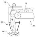
도 1은 종래 기술에 따른 운송물 처리장치의 도면이다.1 is a view of a vehicle handling apparatus according to the prior art.
도 1을 참고하면, 종래의 운송물 처리장치(10)는 연속적으로 공급되는 운송물(M)을 이송하기 위한 제1컨베이어(20)를 포함할 수 있다. 또한, 운송물 처리장치(10)는 제1컨베이어(20)로부터 공급되는 운송물(M)을 제2컨베이어(40)로 안내하는 슈트부(30)를 포함할 수 있다.Referring to FIG. 1, the conventional
운송물 처리장치(10)는 선박 등과 근접하여 배치되며, 이를 위해 선박이 접안할 수 있도록 제공된 바다 등에 마련된 원료부두의 선석 등에 설치될 수 있다.The
그런데, 최근에는 선박의 대형화와 함께 운송량이 증가함에 따라 운송물(M)을 운송하는 데 소요되는 시간이 증가하고 있으며, 이에 따라 선박이 원료부두에 머무르기 위해 지불되는 체선비용도 증가하고 있다.However, in recent years, the time required to transport the transport (M) increases with the increase of the transport volume along with the enlargement of the ship, and accordingly, the cost of the ship to be paid for the ship to stay in the wharf is also increasing.
한편, 운송물(M)의 운송량을 증가시키기 위해서는 벨트콘베이어 설비를 포함하는 운송물 처리장치(10)를 증설하여야 하나, 운송물 처리장치(10)가 설치되는 선석이 통상 바다 등에 설치되는바, 이러한 선석의 투자에 막대한 비용과 시간이 소요되고 있으며, 부두의 면적 제한으로 인해 운송물 처리장치(10)를 증설하기 어려운 실정이다.On the other hand, in order to increase the amount of transportation of the transport (M), but the
이에 따라 종래의 운송물 처리장치(10)는 선박으로부터 운송되는 운송물(M)의 운송속도를 증가시켜 운송물(M)의 운송량을 증가시키고 있으나, 지상 등에 설치된 시설물에서 증가된 운송물(M)의 운송량을 적절하게 분배하기 어려운 문제가 있다.Accordingly, the conventional
이에 따라 최근의 운송물 처리장치(10)는 선박 등으로부터 빠르게 공급되어 운송되는 운송물(M)을 적절하게 분기하여 공급하도록 제공되고 있으나, 종래의 운송물 처리장치(10)는 어느 하나의 운송라인으로 운송물(M)을 분기하여 공급하도록 제공되는 것으로서 순간적으로 운송물(M)의 운송량이 증가할 경우, 운송물(M)을 적절하게 분기할 수 없는 한계가 있다.Accordingly, the recent
본 발명의 일 실시예는 공급되는 운송물을 신속하게 분배하여 처리하도록 한 운송물 분배장치 및 이를 구비한 운송물 처리장치를 제공하는 것을 목적으로 한다.One embodiment of the present invention is to provide a transport distribution device and a transport processing apparatus having the same to quickly distribute and process the transported goods to be supplied.
본 발명의 일 측면에 따른 운송물 분배장치는 운송물 운송부와 복수의 운송물 수용부 사이에 제공되어 운송물의 이동을 안내하는 안내부; 및 안내부에 설치되어 운송물 운송부로부터 공급되는 운송물이 복수의 운송물 수용부 중 적어도 하나에 선택적으로 공급되도록 낙하방향을 조절하는 운송물 낙하방향 조절유닛;을 포함한다.According to one aspect of the invention The package distribution device may include: a guide unit provided between the package transport unit and the plurality of package receiving units to guide the movement of the package; And a transport object drop direction adjusting unit installed in the guide part and configured to adjust a drop direction to selectively supply a transport object supplied from the transport object transport unit to at least one of the plurality of transport object receiving units.
여기서, 운송물 낙하방향 조절유닛은 운송물 운송부로부터 공급되는 운송물과 접촉하며 낙하방향을 전환하는 가동댐퍼를 포함할 수 있다.Here, the shipment drop direction control unit may include a movable damper in contact with the shipment supplied from the shipment transport unit to switch the fall direction.
또한, 가동댐퍼는 운송물 운송부의 폭방향으로 다수개로 분할되어 댐퍼플레이트를 포함할 수 있다.In addition, the movable damper may be divided into a plurality in the width direction of the transport portion transport may include a damper plate.
또한, 가동댐퍼의 회전축에 설치되어 가동댐퍼의 회전량을 제어하는 구동부를 더 포함할 수 있다.The apparatus may further include a driving unit installed on the rotation shaft of the movable damper to control the amount of rotation of the movable damper.
또한, 본 발명의 다른 측면에 따른 운송물 처리장치는 운송물 운송부; 운송물 운송부의 하부에 마련되는 복수의 운송물 수용부; 및 운송물 운송부와 복수의 운송물 수용부를 연계하는 전술된 운송물 분배장치;를 포함한다.In addition, according to another aspect of the present invention Shipment handling apparatus is a transport transport unit; A plurality of transport accommodations provided under the transport transport; And the above-described shipment distribution device for linking the shipment transport unit and the plurality of shipment accommodation units.
여기서, 운송물 분배장치는 운송물 운송부로부터 공급되는 운송물과 접촉하며 낙하방향을 전환하는 가동댐퍼를 포함하고, 가동댐퍼의 회전축에 설치되어 가동댐퍼의 회전량을 제어하는 구동부를 더 포함할 수 있다.Here, the vehicle distribution device may include a movable damper contacting the vehicle supplied from the vehicle transport unit and changing the drop direction, and may further include a driving unit installed on the rotating shaft of the movable damper to control the amount of rotation of the movable damper.
또한, 운송물 운송부에 의해 이동되는 운송물의 운송량을 측정하기 위한 운송량 측정부를 더 포함하고, 운송량 측정부에 측정된 운송물의 운송량에 따라 구동부를 구동시켜 가동댐퍼의 설치각도를 조절할 수 있다.The apparatus may further include a transport amount measuring unit for measuring a transport amount of the transported goods transported by the transport transport unit, and may adjust the installation angle of the movable damper by driving the driving unit according to the transport amount of the transported product measured by the transport amount measuring unit.
또한, 운송물 운송부는 운송물 분배장치에 대해 진퇴 가능하게 설치될 수 있다.In addition, the vehicle transport unit may be installed to be retractable relative to the vehicle distribution device.
또한, 운송물 분배장치는 운송물 운송부에 대해 진퇴 가능하게 설치될 수 있다.In addition, the package distribution device may be installed to be retractable relative to the package transport unit.
또한, 운송물 수용부는 호퍼 또는 다른 운송물 운송부와 연계되는 슈트를 포함할 수 있다.The shipment receptacle may also include a chute associated with the hopper or other shipment hauler.
운송물은 원료광석 또는 철광석을 포함할 수 있다.The shipment may include raw or iron ore.
본 발명의 일 실시예에 따르면, 운송물 처리장치의 운송물을 신속하게 분배하여 운송함으로써 운송물의 운송량을 증가시킬 수 있다. 또한, 본 실시예는 원료부두의 선석 등의 크기를 증가시키지 않더라도 증가된 운송물을 적절하게 분배하여 하역할 수 있으며, 기존에 설치된 벨트 컨베이어 등을 활용하여 최소의 비용을 투자하여 물류량을 증가시킬 수 있다. According to one embodiment of the present invention, by rapidly distributing the transport of the transport processing device it can increase the transport amount of the transport. In addition, the present embodiment can be unloaded by appropriately distributing the increased transport, even without increasing the size of the berths of the raw material pier, it is possible to increase the logistics volume by investing a minimum cost by using the existing belt conveyor, etc. have.
이와 같이, 본 실시예는 선박 등으로부터 운송되는 운송물을 신속하게 운송할 수 있으므로, 선박이 원료부두 등에 정박하는 시간을 줄일 수 있으며, 이에 따라 선박의 체선비용을 줄일 수 있고, 운송물의 운송에 따른 전체적인 물류비용을 절감할 수 있다.As described above, the present embodiment can quickly transport the cargo transported from the ship, etc., thereby reducing the time for the ship to anchor in the raw material wharf, etc., thereby reducing the cost of the ship's body, and The overall logistics cost can be reduced.
도 1은 종래 기술에 따른 운송물 처리장치의 도면.
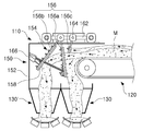
도 2는 본 발명의 일 실시예에 따른 운송물 처리장치의 도면.
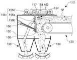
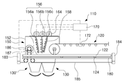
도 3은 본 발명의 일 실시예에 따른 운송물 처리장치의 가동댐퍼가 후방으로 이동한 상태의 도면.
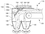
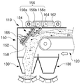
도 4는 본 발명의 일 실시예에 따른 운송물 처리장치의 가동댐퍼가 전방으로 이동한 상태의 도면.
도 5는 본 발명의 일 실시예에 따른 운송물 처리장치의 내부를 보인 정면도.
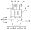
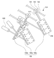
도 6은 본 발명의 일 실시예에 따른 운송물 처리장치의 가동댐퍼를 도시한 사시도.
도 7은 본 발명의 일 실시예에 따른 운송물 처리장치를 간략하게 도시한 구성도.
도 8은 본 발명의 일 실시예에 따른 운송물 처리장치의 운송물 운송부가 안내부로 진입된 상태의 도면.
도 9는 본 발명의 일 실시예에 따른 운송물 처리장치의 운송물 운송부가 안내부에서 퇴각된 상태의 도면.
도 10은 본 발명의 일 실시예에 따른 운송물 처리장치의 운송물 운송부 및 운송물 분배장치가 퇴각된 상태의 도면.1 is a view of a shipment processing apparatus according to the prior art.
2 is a view of a vehicle processing apparatus according to an embodiment of the present invention.
3 is a view of a state in which the movable damper of the transport processing apparatus according to an embodiment of the present invention moved rearward.
4 is a view of a state in which the movable damper of the transport processing apparatus according to an embodiment of the present invention moved forward.
Figure 5 is a front view showing the inside of the shipment processing apparatus according to an embodiment of the present invention.
Figure 6 is a perspective view showing a movable damper of the vehicle processing apparatus according to an embodiment of the present invention.
Figure 7 is a schematic diagram showing a vehicle handling apparatus according to an embodiment of the present invention.
8 is a view illustrating a state in which a transportation unit of the transportation processing apparatus according to an embodiment of the present invention enters the guide unit.
9 is a view of a state in which the transport portion of the transport of the transport processing apparatus according to an embodiment of the present invention withdrawn from the guide.
10 is a view of a state in which a vehicle transport unit and a vehicle distribution device of the vehicle processing apparatus according to an embodiment of the present invention are retreated;
이하, 본 발명의 일 실시예를 첨부한 도면을 참조하여 상세히 설명한다. 본 발명의 실시형태는 여러 가지의 다른 형태로 변형될 수 있으며, 본 발명의 범위가 이하 설명하는 실시형태로만 한정되는 것은 아니다. 도면에서의 요소들의 형상 및 크기 등은 보다 명확한 설명을 위해 과장될 수 있으며, 도면상의 동일한 부호로 표시되는 요소는 동일한 요소이다.
Hereinafter, an embodiment of the present invention will be described in detail with reference to the accompanying drawings. The embodiments of the present invention can be modified into various other forms, and the scope of the present invention is not limited to the embodiments described below. The shape and the size of the elements in the drawings may be exaggerated for clarity and the same elements are denoted by the same reference numerals in the drawings.
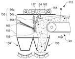
도 2는 본 발명의 일 실시예에 따른 운송물 처리장치의 도면이다. 또한, 도 3은 본 발명의 일 실시예에 따른 운송물 처리장치의 가동댐퍼가 후방으로 이동한 상태의 도면이고, 도 4는 본 발명의 일 실시예에 따른 운송물 처리장치의 가동댐퍼가 전방으로 이동한 상태의 도면이다. 또한, 도 5는 본 발명의 일 실시예에 따른 운송물 처리장치의 내부를 보인 정면도이다. 또한, 도 6은 본 발명의 일 실시예에 따른 운송물 처리장치의 가동댐퍼를 도시한 사시도다.2 is a view of a vehicle processing apparatus according to an embodiment of the present invention. 3 is a view showing a state in which the movable damper of the transport processing apparatus according to an embodiment of the present invention is moved rearward, and FIG. 4 is a movable damper of the transport processing apparatus according to an embodiment of the present invention moving forward. It is a figure of a state. In addition, Figure 5 is a front view showing the interior of the vehicle processing apparatus according to an embodiment of the present invention. 6 is a perspective view showing a movable damper of a vehicle processing apparatus according to an embodiment of the present invention.
도 2 내지 도 6을 참고하면, 본 실시예에 따른 운송물 처리장치(110)는 운송물(M)을 연속적으로 운송하는 운송물 운송부(120)를 포함하며, 이 운송물 운송부(120)의 하부에는 운송물 운송부(120)로부터 운송된 운송물(M)이 수용되는 운송물 수용부(130)가 제공될 수 있다.2 to 6, the
본 실시예에서 운송물 수용부(130)는 복수개로 이루어질 수 있으며, 운송물 운송부(120)의 하부에 마련되어 운송물(M)을 분기하여 수용할 수 있다.In the present embodiment, the
이를 위해, 운송물 운송부(120)와 복수의 운송물 수용부(130)에는 운송물(M)을 분기하여 공급하기 위한 운송물 분배장치(150)가 연계될 수 있다.To this end, the
운송물 분배장치(150)는 운송물(M)의 이동을 안내하기 위한 안내부(152)를 포함할 수 있다. 안내부(152)는 운송물 운송부(120)와 복수의 운송물 수용부(130) 사이에 제공될 수 있다.The
안내부(152)는 일측에 운송물 운송부(120)가 진입될 수 있도록 입구가 형성되고, 입구로 진입된 운송물 운송부(120)로부터 공급된 운송물(M)을 복수의 운송물 수용부(130)로 배출하기 위한 배출부가 구비될 수 있다.
또한, 운송물 분배장치(150)는 안내부(152)에 설치된 운송물 낙하방향 조절유닛(154)을 포함할 수 있다.In addition, the
운송물 낙하방향 조절유닛(154)은 운송물 운송부(120)로부터 공급된 운송물(M)의 낙하방향을 조절함으로써, 운송물(M)이 복수의 운송물 수용부(130) 중 적어도 하나에 선택적으로 수용되도록 낙하방향을 조절할 수 있다.The shipment drop
일례로, 본 실시예에서 운송물 낙하방향 조절유닛(154)은 안내부(152)의 상부에 설치되어 운송물 운송부(120)으로부터 공급된 운송물(M)이 부딪힌 후, 각도가 가변되며 낙하하도록 제공될 수 있다.For example, in the present embodiment, the shipment drop
이를 위해, 운송물 낙하방향 조절유닛(154)은 운송물 운송부(120)로부터 공급되는 운송물(M)과 접촉하는 가동댐퍼(156)를 포함하며, 이 가동댐퍼(156)는 일측이 안내부(152)의 상부에 소정의 각도를 유지하도록 설치될 수 있다.To this end, the shipment drop
따라서, 운송물 운송부(120)로부터 공급되는 운송물(M)은 운송물 수용부(130)로 낙하되는 과정에서 가동댐퍼(156)에 부딪힐 수 있으며, 이 과정에서 운송물(M)의 자중 및 가동댐퍼(156)에 부딪히는 위치 등에 따라 일부는 운송물 운송부(120)와 인접한 운송물 수용부(130)로 낙하되고, 다른 일부는 운송물 운송부(120)와 멀리 떨어진 운송물 수용부(130')로 낙하될 수 있다.Therefore, the vehicle M supplied from the
본 실시예에서 가동댐퍼(156)는 운송물 운송부(120)의 폭방향으로 다수개로 분할되어 배치되는 복수의 댐퍼 플레이트(156a, 156b, 156c)를 포함할 수 있다.In the present exemplary embodiment, the
그리고, 댐퍼 플레이트(156a, 156b, 156c)는 운송물(M)과 접촉하는 면에 내마모성을 갖는 재질의 라이너(158)가 설치될 수 있다. 이러한 라이너(158)는 댐퍼 플레이트(156a, 156b, 156c)의 접촉면에 볼트 등에 체결될 수 있다.In addition, the
이들 댐퍼 플레이트(156a, 156b, 156c)는 각각의 설치된 각도를 유지하도록 설치될 수 있다.These
즉, 가동댐퍼(156)는 이들 댐퍼 플레이트(156a, 156b, 156c) 중 중앙부에 위치한 댐퍼 플레이트(156b)는 외곽부에 위치한 댐퍼 플레이트(156a, 156c)들보다 운송물 운송부(120)에서 멀어지는 방향으로 더 경사지게 설치될 수 있다.That is, the
이에 따라 운송물 운송부(120)의 중앙부에 적재되어 안내부(152)로 투입된 운송물(M)은 가동댐퍼(156)의 중앙부 댐퍼 플레이트(156b)에 부딪힌 후, 운송물 운송부(120)와 멀리 떨어진 운송물 수용부(130')로 낙하할 수 있다.Accordingly, the transport object M loaded into the center portion of the
또한, 운송물 운송부(120)의 외곽부에 적재되어 안내부(152)로 투입된 운송물(M)은 가동댐퍼(156)의 외곽부 댐퍼 플레이트(156a, 156c)에 부딪힌 후, 운송물 운송부(120)와 인접한 운송물 수용부(130)로 낙하할 수 있다.In addition, the transport object M loaded on the outer portion of the
이때, 가동댐퍼(156)의 각 댐퍼 플레이트(156a, 156b, 156c)는 운송물(M)의 자중 또는 운송물(M)의 운송량이나, 운송속도 등에 따라 설치된 각도가 조절될 수 있으며, 이러한 각 댐퍼 플레이트(156a, 156b, 156c)의 각도 조절을 통해 각각의 운송물 수용부(130, 130')로 낙하는 운송물(M)의 분배량을 일정하게 유지할 수 있다.At this time, each damper plate (156a, 156b, 156c) of the
본 실시예에서 가동댐퍼(156)의 각 댐퍼 플레이트(156a, 156b, 156c)는 작업자에 의해 수동으로 설치된 각도가 조절될 수 있으며, 바람직하게는 각 댐퍼 플레이트(156a, 156b, 156c)의 각도를 자동으로 조절하기 위한 구동부(160)를 더 포함할 수 있다.In this embodiment, the
일례로, 본 실시예에서 안내부(152)의 상부에는 전후방향, 즉 운송물(M)이 운송되는 방향에 대해 전후방향으로 가이드바(162)가 설치되고, 이 가이드바(162)에는 구동부(160) 및 구동부(160)가 설치된 브래킷(164)이 전, 후로 이동 가능하게 설치될 수 있다.For example, in the present exemplary embodiment, the
그리고, 댐퍼 플레이트(156a, 156b, 156c)는 상부에 지지바(157)가 설치될 수 있으며, 이 지지바(157)는 브래킷(164)의 내측으로 연장된 구동부(160)의 회전축에 결합될 수 있다.In addition, the
댐퍼 플레이트(156a, 156b, 156c)는 구동부(160)의 작동에 따라 회전축이 회전함에 따라 지지바(157)가 회전하며 설치된 각도가 조절될 수 있다.The
또한, 안내부(152)의 내측에는 가동댐퍼(156)의 각 댐퍼 플레이트(156a, 156b, 156c)에 연결되는 복수의 액츄에이터(166)가 설치될 수 있다.In addition, a plurality of
이 액츄에이터(166)는 각 댐퍼 플레이트(156a, 156b, 156c)의 후면에 설치되며, 운송물 운송부(120)에 의해 운송물(M)이 부딪힐 경우 발생하는 충격에 의해 댐퍼 플레이트(156a, 156b, 156c)가 후방으로 밀리는 것을 지지하도록 제공된다.The
또한, 액츄에이터(166)는 댐퍼 플레이트(156a, 156b, 156c)를 간헐적으로 유동시킬 수 있으며, 이에 따라 댐퍼 플레이트(156a, 156b, 156c)에 부착된 운송물(M)을 탈락시킬 수 있다.In addition, the
더불어, 본 실시예에서 가동댐퍼(156)의 각 댐퍼 플레이트(156a, 156b, 156c)는 구동부(160)에 의해 설치된 각도가 조절되는 것으로 개시되어 있으나, 구동부(160) 외에 액츄에이터(166)를 이용하여 가동댐퍼(156)의 각 댐퍼 플레이트(156a, 156b, 156c)가 설치된 각도를 조정하는 것도 가능하다.In addition, in this embodiment, each damper plate (156a, 156b, 156c) of the
여기서, 액츄에이터(166)는 유압 등에 작동하는 실린더 유닛이 사용될 수 있다. In this case, the
도 7은 본 발명의 일 실시예에 따른 운송물 처리장치를 간략하게 도시한 구성도이다. 또한, 도 8은 본 발명의 일 실시예에 따른 운송물 처리장치의 운송물 운송부가 안내부로 진입된 상태의 도면이고, 도 9는 본 발명의 일 실시예에 따른 운송물 처리장치의 운송물 운송부가 안내부에서 퇴각된 상태의 도면이며, 도 10은 본 발명의 일 실시예에 따른 운송물 처리장치의 운송물 운송부 및 운송물 분배장치가 퇴각된 상태의 도면이다.Figure 7 is a schematic diagram showing a vehicle handling apparatus according to an embodiment of the present invention. 8 is a view illustrating a state in which a transportation unit of a transportation processing apparatus according to an embodiment of the present invention enters a guide unit, and FIG. 9 illustrates a transportation unit of the transportation processing unit according to an embodiment of the present invention in a guide unit. 10 is a view of the retracted state, Figure 10 is a view of the retracted vehicle transport unit and the vehicle distribution device of the transport processing apparatus according to an embodiment of the present invention.
도 7을 참고하면, 본 실시예의 운송물 처리장치(110)는 운송물(M)의 운송량을 측정하기 위한 운송량 측정부를 포함할 수 있다.Referring to FIG. 7, the
운송량 측정부는 운송물(M)의 운송량을 판단하기 위한 센서와, 이러한 센서(172)에 의해 측정된 데이터를 통해 운송물(M)을 운송량을 판단하여 구동부(160)를 제어토록 제공되는 제어부(170)를 포함할 수 있다.The transport amount measuring unit includes a sensor for determining a transport amount of the transport object M, and a
제어부(170)는 구동부(160)의 작동을 제어함에 따라 가동댐퍼(156)의 각 댐퍼 플레이트(156a, 156b, 156c)가 설치된 각도를 조절할 수 있으며, 이에 따라 운송물 운송부(120)로부터 공급되는 운송물(M)이 각 댐퍼 플레이트(156a, 156b, 156c)에 부딪힌 후 각각의 운송물 수용부(130)로 낙하, 공급되는 운송물(M)을 일정하게 유지시킬 수 있다.The
여기서, 운송물(M)의 운송량을 판단하기 위한 센서(172)의 일례로는 로드셀(rod cell)을 포함하는 하중센서가 사용될 수 있으며, 이러한 하중 센서는 운송물 운송부(120)와 직접 접촉되거나 다른 부재에 의해 간접적으로 접촉되며 하중을 측정할 수 있다.Here, a load sensor including a load cell may be used as an example of the
또한, 하중센서는 가동댐퍼(156)의 각 댐퍼 플레이트(156a, 156b, 156c)에 제공될 수 있으며, 운송물(M)이 각각의 댐퍼 플레이트(156a, 156b, 156c)에 부딪히는 충격량을 통해 운송물(M)의 운송량을 측정할 수 있다.In addition, the load sensor may be provided to each damper plate (156a, 156b, 156c) of the movable damper (156), and the shipment (M) by the amount of impact that strikes each of the damper plates (156a, 156b, 156c). The transportation volume of M) can be measured.
또한, 본 실시예에서 운송물 운송부(120)는 운송물 분배장치(150)에 대해 진퇴 가능하게 설치될 수 있다.In addition, in the present embodiment, the
일례로, 운송물 운송부(120)는 안내부(152)의 내부에서 소정 거리 안쪽으로 진입(도 8 참조)되거나 바깥쪽으로 퇴각(도 9 참조)할 수 있다.In one example, the
이때, 운송물 운송부(120)가 진퇴함에 따라 가동댐퍼(156)도 연동하여 이동할 수 있다.At this time, as the
운송물 운송부(120)는, 도 8과 같이, 안내부(152)의 내부에서 안쪽으로 진입하게 되면, 운송물 운송부(120)와 이격되어 있던 운송물 수용부(130')와 인접하게 된다. 더불어, 가동댐퍼(156)의 모든 댐퍼 플레이트(156a, 156b, 156c)는 후방으로 최대로 경사진 각도로 설치될 수 있다.As shown in FIG. 8, when the
그리고, 운송물 운송부(120)는 안내부(152)의 입구에서 먼거리에 위치한 운송물 수용부(130')로 공급되는 운송물(M)의 운송량을 증가시킬 수 있다.In addition, the
한편, 운송물 운송부(120)는, 도 9와 같이, 안내부(152)의 내부에서 바깥쪽으로 퇴각하게 되면, 운송물(M)을 안내부(152)의 입구와 인접한 운송물 수용부(130)로 공급할 수 있다.Meanwhile, as shown in FIG. 9, when the
이와 같이, 본 실시예에서 운송물 운송부(120)는 안내부(152)의 내부에서 진퇴함에 따라 선택된 운송물 수용부(130, 130')로만 운송물을 공급하는 것도 가능하다.As such, in this embodiment, the
이를 위해, 운송물 운송부(120)는 프레임(122)을 포함할 수 있고, 이 프레임(122)의 하부에는 레일(180)이 설치될 수 있다.To this end, the
그리고, 운송물 운송부(120)는 이 레일(180)을 따라 이동할 수 있도록 프레임(122)의 일측에 다수의 차륜(124)이 설치될 수 있다. 또한, 복수의 차륜(124) 중 적어도 하나에는 모터 등의 구동수단이 설치될 수 있으며, 제어부(170)에 의해 모터의 작동을 제어하여 운송물 운송부(120)를 진퇴시킬 수 있다.In addition, the
본 실시예에서 운송물 운송부(120)는 레일(180)에 안착된 차륜(124)을 회전시켜 이동하는 것으로 설명하고 있으나, 운송물 운송부(120)의 진퇴수단은 한정되지 않으며 공지된 다양한 형태의 진퇴수단이 구비될 수 있다.In this embodiment, the
또한, 운송물 처리장치(110)는 운송물 운송부(120)의 과도한 이동을 제한하기 위한 스토퍼부재(183, 184)를 포함할 수 있다. 이 스토퍼부재(183, 184)는 프레임(122)의 전단 또는 후단에 걸리도록 설치될 수 있다.In addition, the
또한, 본 실시예에서 운송물 분배장치(150)는 운송물 운송부(120)에 대해 진퇴 가능하게 설치될 수 있다.In addition, in this embodiment, the
일례로, 운송물 분배장치(150)의 안내부(152)는, 도 10과 같이, 운송물 운송부(120) 방향으로 이동할 수 있으며, 이에 따라 운송물 운송부(120)와 인접한 운송물 수용부(130)는 안내부(152)의 내측에 위치하고, 운송물 운송부(120)와 멀리 이격된 운송물 수용부(130')는 안내부(152)의 외측으로 벗어날 수 있다.In one example, the
또한, 운송물 분배장치(150)는 다시 원래의 위치로 이동할 수 있으며, 이에 따라 모든 운송물 수용부(130)가 안내부(152)의 내측에 위치할 수 있다.In addition, the
또한, 운송물 분배장치(150)는 안내부(152)의 이동과 연동하여 가동댐퍼(156)의 설치각도가 조절될 수 있다.In addition, the
이를 위해, 운송물 분배장치(150)는 진퇴선상에 체인(185)이 고정 설치될 수 있다.To this end, the
그리고, 안내부(152)에는 모터(186)가 설치될 수 있으며, 이 모터(186)에는 스프라켓(187)이 결합되어, 체인(185)에 연결될 수 있다. 이때, 안내부(152)의 모터(186)는 제어부(170)와 연결되며, 제어부(170)에 의해 모터(186)가 구동됨에 따라 스프라켓(187)이 회전하며 안내부(152)를 이동시킬 수 있다.In addition, a
본 실시예에서 운송물 분배장치(150)는 안내부(152)에 설치된 모터(186)가 스프라켓(187)을 회전시킴에 따라 체인(185)을 따라 이동하는 것으로 설명하고 있으나, 운송물 분배장치(150)의 이동수단은 한정되지 않으며 공지의 다양한 기술이 적용될 수 있다.In this embodiment, the
또한, 본 실시예에서 운송물 분배장치(150)는 운송물 운송부(120)와 연동하여 이동할 수 있으며, 이에 따라 운송물(M)을 어느 하나의 운송물 수용부(130 또는 130')로 공급하거나 모든 운송물 수용부(130, 130')로 일정하게 분배하는 것도 가능하다.In addition, in the present embodiment, the
또한, 본 실시예에서, 운송물(M)은 철광산업 등에 사용하는 원료 또는 연료 등을 포함할 수 있다.In addition, in the present embodiment, the transport (M) may include a raw material or fuel used in the iron ore industry and the like.
또한, 본 실시예에서, 운송물 운송부(120)는 원료부두의 선석 등에 설치되는 원료부두측 컨베이어를 포함할 수 있다. In addition, in the present embodiment, the
또한, 운송물 수용부(130)는 이러한 원료 또는 연료 등의 운송물을 저장하기 위한 호퍼 또는 운송물의 배출을 안내하는 슈트를 포함할 수 있으며, 이러한 호퍼 또는 슈트 등에는 운송물을 운송하는 다른 운송물 운송부가 연계될 수 있다.In addition, the
또한, 본 실시예의 운송물 수용부(130)의 일례인, 호퍼 또는 슈트는 운송물 적재부를 갖는 차량 등이 연계될 수 있다.In addition, the hopper or chute, which is an example of the
또한, 운송물 수용부(130)의 일례인, 호퍼 또는 슈트와 연계되는 다른 운송물 운송부는 지상의 처리시설 또는 적재장소로 운송물을 이송하는 지상측 컨베이어를 포함할 수 있다.In addition, another transport transport unit associated with the hopper or chute, which is an example of the
여기서, 원료부두측 컨베이어 또는 지상측 컨베이어는 각각에 설치된 벨트 등을 연속적으로 순환시키며, 벨트에 적재된 운송물을 연속적으로 운송할 수 있도록 제공될 수 있다.
Here, the raw material pier side conveyor or ground side conveyor may be provided to continuously circulate the belt and the like installed on each, and to continuously transport the goods loaded on the belt.
본 발명은 상술한 실시형태 및 첨부된 도면에 의해 한정되지 아니하며, 청구범위에 기재된 본 발명의 기술적 사상을 벗어나지 않는 범위 내에서 다양한 형태의 치환, 변형 및 변경이 가능하다는 것은 당 기술분야의 통상의 지식을 가진 자에게 자명할 것이다.It will be understood by those skilled in the art that various changes in form and details may be made therein without departing from the spirit and scope of the invention as defined by the appended claims and their equivalents. It will be clear to those who have knowledge.
110 : 운송물 처리장치 120 : 운송물 운송부
122 : 프레임 124 : 차륜
130, 130' : 운송물 수용부 150 : 운송물 분배장치
152 : 안내부 운송물 154 : 낙하방향 조절유닛
156 : 가동댐퍼 156a, 156b, 156c : 댐퍼 플레이트
157 : 지지바 158 : 라이너
160 : 구동부 162 : 가이드바
164 : 브래킷 166 : 액츄에이터
170 : 제어부 172 : 센서
180 : 레일 183, 184 : 스토퍼부재
185 : 체인 186 : 모터
M : 운송물110: transport processing device 120: transport transport unit
122: frame 124: wheel
130, 130 ': transport container 150: transport distribution device
152: guide transport goods 154: falling direction control unit
156:
157: support bar 158: liner
160: drive unit 162: guide bar
164: bracket 166: actuator
170: control unit 172: sensor
180:
185: chain 186: motor
M: Shipment
Claims (11)
안내부에 설치되어 운송물 운송부로부터 공급되는 운송물이 복수의 운송물 수용부 중 적어도 하나에 선택적으로 공급되도록 낙하방향을 조절하는 운송물 낙하방향 조절유닛;
을 포함하는 운송물 분배장치.
A guide unit provided between the vehicle transport unit and the plurality of package accommodation units to guide the movement of the package;
A shipment drop direction adjusting unit installed in the guide to adjust a drop direction so that a shipment supplied from the shipment transport unit is selectively supplied to at least one of the plurality of shipment receiving units;
Transport distribution device comprising a.
운송물 낙하방향 조절유닛은 운송물 운송부로부터 공급되는 운송물과 접촉하며 낙하방향을 전환하는 가동댐퍼를 포함하는 것을 특징으로 하는 운송물 분배장치.
The method according to claim 1,
The shipment drop direction control unit comprises a movable damper in contact with the shipment supplied from the shipment transport unit and a movable damper for switching the drop direction.
가동댐퍼는 운송물 운송부의 폭방향으로 다수개로 분할되어 댐퍼플레이트를 포함하는 것을 특징으로 하는 운송물 분배장치.
The method according to claim 2,
Movable damper is divided into a plurality in the width direction of the transport portion transport material distribution apparatus characterized in that it comprises a damper plate.
가동댐퍼의 회전축에 설치되어 가동댐퍼의 회전량을 제어하는 구동부를 더 포함하는 것을 특징으로 하는 운송물 분배장치.
The method according to claim 2 or 3,
And a drive unit installed on the rotary shaft of the movable damper to control the amount of rotation of the movable damper.
운송물 운송부의 하부에 마련되는 복수의 운송물 수용부; 및
운송물 운송부와 복수의 운송물 수용부를 연계하는 청구항 1 내지 청구항 3 중 어느 한 항에 따른 운송물 분배장치;
를 포함하는 운송물 처리장치.
Transportation Department;
A plurality of transport accommodations provided under the transport transport; And
Claims 1-3 according to any one of claims 1 to 3 linking the conveying material transport unit and the plurality of conveying goods receiving unit;
Transport processing apparatus comprising a.
운송물 분배장치는 운송물 운송부로부터 공급되는 운송물과 접촉하며 낙하방향을 전환하는 가동댐퍼를 포함하고,
가동댐퍼의 회전축에 설치되어 가동댐퍼의 회전량을 제어하는 구동부를 더 포함하는 것을 특징으로 하는 운송물 처리장치.
The method according to claim 5,
The package distribution device includes a movable damper that contacts the package supplied from the package carrying unit and changes the drop direction.
And a driving unit installed on the rotary shaft of the movable damper to control the amount of rotation of the movable damper.
운송물 운송부에 의해 이동되는 운송물의 운송량을 측정하기 위한 운송량 측정부를 더 포함하고,
운송량 측정부에 측정된 운송물의 운송량에 따라 구동부를 구동시켜 가동댐퍼의 설치각도를 조절하는 것을 특징으로 하는 운송물 처리장치.
The method of claim 6,
Further comprising a transport amount measuring unit for measuring the transport amount of the transported goods moved by the transport transport unit,
And a driving angle of the driving unit in accordance with the transportation amount measured in the transportation measurement unit to adjust the installation angle of the movable damper.
운송물 운송부는 운송물 분배장치에 대해 진퇴 가능하게 설치되는 것을 특징으로 하는 운송물 처리장치.
The method according to claim 5,
The transportation material transport unit is characterized in that the transportation equipment is installed to be retractable with respect to the distribution device.
운송물 분배장치는 운송물 운송부에 대해 진퇴 가능하게 설치되는 것을 특징으로 하는 운송물 처리장치.
The method according to claim 5,
The shipment distribution device is a shipment processing device, characterized in that the retractable installation for the transportation transport.
상기 운송물 수용부는 호퍼 또는 다른 운송물 운송부와 연계되는 슈트를 포함하는 것을 특징으로 하는 운송물 처리장치.
The method according to claim 5,
The shipment receiving unit includes a chute associated with a hopper or other shipment carrying unit.
상기 운송물은 원료광석 또는 철광석을 포함하는 것을 특징으로 하는 운송물 처리장치.The method according to claim 5,
The shipment is a processing device, characterized in that it comprises a raw ore or iron ore.
Priority Applications (1)
| Application Number | Priority Date | Filing Date | Title |
|---|---|---|---|
| KR1020110036750A KR101253884B1 (en) | 2011-04-20 | 2011-04-20 | Materials distrubute device and materials treatment apparatus having the same |
Applications Claiming Priority (1)
| Application Number | Priority Date | Filing Date | Title |
|---|---|---|---|
| KR1020110036750A KR101253884B1 (en) | 2011-04-20 | 2011-04-20 | Materials distrubute device and materials treatment apparatus having the same |
Publications (2)
| Publication Number | Publication Date |
|---|---|
| KR20120119030A true KR20120119030A (en) | 2012-10-30 |
| KR101253884B1 KR101253884B1 (en) | 2013-04-16 |
Family
ID=47286354
Family Applications (1)
| Application Number | Title | Priority Date | Filing Date |
|---|---|---|---|
| KR1020110036750A Expired - Fee Related KR101253884B1 (en) | 2011-04-20 | 2011-04-20 | Materials distrubute device and materials treatment apparatus having the same |
Country Status (1)
| Country | Link |
|---|---|
| KR (1) | KR101253884B1 (en) |
Cited By (2)
| Publication number | Priority date | Publication date | Assignee | Title |
|---|---|---|---|---|
| KR101373166B1 (en) * | 2012-11-30 | 2014-03-13 | 주식회사 포스코 | Chute with function of controlling falling object direction |
| KR101424451B1 (en) * | 2012-11-28 | 2014-08-04 | 현대제철 주식회사 | Transferring apparatus for fuel and raw material |
Families Citing this family (1)
| Publication number | Priority date | Publication date | Assignee | Title |
|---|---|---|---|---|
| KR101999572B1 (en) * | 2019-01-15 | 2019-07-15 | (주)신대양 | Thermal desorption device capable of uniform heat treatment |
Family Cites Families (4)
| Publication number | Priority date | Publication date | Assignee | Title |
|---|---|---|---|---|
| JPH07237742A (en) * | 1994-02-28 | 1995-09-12 | Asahi Glass Co Ltd | Transfer path direction switching device |
| KR200278684Y1 (en) * | 1998-07-24 | 2002-09-19 | 주식회사 포스코 | Head chute damper |
| JP3822766B2 (en) * | 1999-08-09 | 2006-09-20 | 新日本製鐵株式会社 | Distributing device in bulk material transfer line |
| KR20020037947A (en) * | 2000-11-16 | 2002-05-23 | 이구택 | An equally sharing apparatus for chute |
-
2011
- 2011-04-20 KR KR1020110036750A patent/KR101253884B1/en not_active Expired - Fee Related
Cited By (2)
| Publication number | Priority date | Publication date | Assignee | Title |
|---|---|---|---|---|
| KR101424451B1 (en) * | 2012-11-28 | 2014-08-04 | 현대제철 주식회사 | Transferring apparatus for fuel and raw material |
| KR101373166B1 (en) * | 2012-11-30 | 2014-03-13 | 주식회사 포스코 | Chute with function of controlling falling object direction |
Also Published As
| Publication number | Publication date |
|---|---|
| KR101253884B1 (en) | 2013-04-16 |
Similar Documents
| Publication | Publication Date | Title |
|---|---|---|
| CN109720893B (en) | Throwing device, loading machine head and bagged object loading method | |
| JP5558748B2 (en) | Fruit and vegetable transport and delivery method, fruit and vegetable transport and delivery device | |
| US8534443B2 (en) | Apparatus for stacking and reclaiming material | |
| CN102143901A (en) | Store-feeding device, and method for the operation of such a store-feeding device | |
| CN212049636U (en) | Material distributing and distributing device | |
| KR101330534B1 (en) | Control device of material supply | |
| KR101253884B1 (en) | Materials distrubute device and materials treatment apparatus having the same | |
| KR20040010301A (en) | A storage wagon including a sensor device | |
| US11046535B2 (en) | Storage apparatus for bulk material, in particular wood chips, and a filling method | |
| CN101863387A (en) | Mobile corrugated sidewall belt conveyor | |
| KR101435050B1 (en) | Transfer apparatus for rotary feeder of continuous ship unloader | |
| KR101393685B1 (en) | Hanging chute for rotary discharge machine | |
| US2758732A (en) | Conveying and unloading mechanism | |
| RU2577350C2 (en) | System for heaping, storing and distributing of fodder at vessels meant for transportation of large amount of cattle | |
| US3384248A (en) | Unloading system and method | |
| US3067891A (en) | Article handling apparatus and system | |
| KR101399859B1 (en) | Continuous ship unloader | |
| JP2000211744A (en) | Dispensing device and dispensing method for continuous unloader | |
| JP2000038193A (en) | Automatic loading equipment for bulk carriers | |
| CN220165260U (en) | Hopper belt conveyor | |
| KR101291533B1 (en) | Transferring apparatus for fuel and raw material in continuous ship unloader | |
| JP7252804B2 (en) | Bulk cargo unloading device | |
| JP6656814B2 (en) | Stacker control method | |
| RU2773483C2 (en) | Device for storing bulk material, in particular wood chip, and filling method | |
| JP7233996B2 (en) | Bulk item unloading device and installation method for bulk item unloading device |
Legal Events
| Date | Code | Title | Description |
|---|---|---|---|
| A201 | Request for examination | ||
| PA0109 | Patent application |
St.27 status event code: A-0-1-A10-A12-nap-PA0109 |
|
| PA0201 | Request for examination |
St.27 status event code: A-1-2-D10-D11-exm-PA0201 |
|
| PG1501 | Laying open of application |
St.27 status event code: A-1-1-Q10-Q12-nap-PG1501 |
|
| D13-X000 | Search requested |
St.27 status event code: A-1-2-D10-D13-srh-X000 |
|
| D14-X000 | Search report completed |
St.27 status event code: A-1-2-D10-D14-srh-X000 |
|
| E902 | Notification of reason for refusal | ||
| PE0902 | Notice of grounds for rejection |
St.27 status event code: A-1-2-D10-D21-exm-PE0902 |
|
| E13-X000 | Pre-grant limitation requested |
St.27 status event code: A-2-3-E10-E13-lim-X000 |
|
| P11-X000 | Amendment of application requested |
St.27 status event code: A-2-2-P10-P11-nap-X000 |
|
| P13-X000 | Application amended |
St.27 status event code: A-2-2-P10-P13-nap-X000 |
|
| E701 | Decision to grant or registration of patent right | ||
| PE0701 | Decision of registration |
St.27 status event code: A-1-2-D10-D22-exm-PE0701 |
|
| GRNT | Written decision to grant | ||
| PR0701 | Registration of establishment |
St.27 status event code: A-2-4-F10-F11-exm-PR0701 |
|
| PR1002 | Payment of registration fee |
St.27 status event code: A-2-2-U10-U11-oth-PR1002 Fee payment year number: 1 |
|
| PG1601 | Publication of registration |
St.27 status event code: A-4-4-Q10-Q13-nap-PG1601 |
|
| FPAY | Annual fee payment |
Payment date: 20160405 Year of fee payment: 4 |
|
| PR1001 | Payment of annual fee |
St.27 status event code: A-4-4-U10-U11-oth-PR1001 Fee payment year number: 4 |
|
| P22-X000 | Classification modified |
St.27 status event code: A-4-4-P10-P22-nap-X000 |
|
| PR1001 | Payment of annual fee |
St.27 status event code: A-4-4-U10-U11-oth-PR1001 Fee payment year number: 5 |
|
| FPAY | Annual fee payment |
Payment date: 20180405 Year of fee payment: 6 |
|
| PR1001 | Payment of annual fee |
St.27 status event code: A-4-4-U10-U11-oth-PR1001 Fee payment year number: 6 |
|
| R18-X000 | Changes to party contact information recorded |
St.27 status event code: A-5-5-R10-R18-oth-X000 |
|
| FPAY | Annual fee payment |
Payment date: 20190403 Year of fee payment: 7 |
|
| PR1001 | Payment of annual fee |
St.27 status event code: A-4-4-U10-U11-oth-PR1001 Fee payment year number: 7 |
|
| R18-X000 | Changes to party contact information recorded |
St.27 status event code: A-5-5-R10-R18-oth-X000 |
|
| R18-X000 | Changes to party contact information recorded |
St.27 status event code: A-5-5-R10-R18-oth-X000 |
|
| PR1001 | Payment of annual fee |
St.27 status event code: A-4-4-U10-U11-oth-PR1001 Fee payment year number: 8 |
|
| PR1001 | Payment of annual fee |
St.27 status event code: A-4-4-U10-U11-oth-PR1001 Fee payment year number: 9 |
|
| P22-X000 | Classification modified |
St.27 status event code: A-4-4-P10-P22-nap-X000 |
|
| R18-X000 | Changes to party contact information recorded |
St.27 status event code: A-5-5-R10-R18-oth-X000 |
|
| PN2301 | Change of applicant |
St.27 status event code: A-5-5-R10-R11-asn-PN2301 |
|
| PR1001 | Payment of annual fee |
St.27 status event code: A-4-4-U10-U11-oth-PR1001 Fee payment year number: 10 |
|
| PN2301 | Change of applicant |
St.27 status event code: A-5-5-R10-R14-asn-PN2301 |
|
| R18-X000 | Changes to party contact information recorded |
St.27 status event code: A-5-5-R10-R18-oth-X000 |
|
| PC1903 | Unpaid annual fee |
St.27 status event code: A-4-4-U10-U13-oth-PC1903 Not in force date: 20230406 Payment event data comment text: Termination Category : DEFAULT_OF_REGISTRATION_FEE |
|
| R18-X000 | Changes to party contact information recorded |
St.27 status event code: A-5-5-R10-R18-oth-X000 |
|
| PC1903 | Unpaid annual fee |
St.27 status event code: N-4-6-H10-H13-oth-PC1903 Ip right cessation event data comment text: Termination Category : DEFAULT_OF_REGISTRATION_FEE Not in force date: 20230406 |
|
| R18 | Changes to party contact information recorded |
Free format text: ST27 STATUS EVENT CODE: A-5-5-R10-R18-OTH-X000 (AS PROVIDED BY THE NATIONAL OFFICE) |
|
| R18-X000 | Changes to party contact information recorded |
St.27 status event code: A-5-5-R10-R18-oth-X000 |