KR20120119065A - Insulation structure of lng cargo tank, method for constructing the same and ship having the same - Google Patents
Insulation structure of lng cargo tank, method for constructing the same and ship having the same Download PDFInfo
- Publication number
- KR20120119065A KR20120119065A KR1020110036809A KR20110036809A KR20120119065A KR 20120119065 A KR20120119065 A KR 20120119065A KR 1020110036809 A KR1020110036809 A KR 1020110036809A KR 20110036809 A KR20110036809 A KR 20110036809A KR 20120119065 A KR20120119065 A KR 20120119065A
- Authority
- KR
- South Korea
- Prior art keywords
- cargo hold
- metal plate
- lng cargo
- insulation
- insulating
- Prior art date
- Legal status (The legal status is an assumption and is not a legal conclusion. Google has not performed a legal analysis and makes no representation as to the accuracy of the status listed.)
- Granted
Links
Images


Classifications
-
- B—PERFORMING OPERATIONS; TRANSPORTING
- B63—SHIPS OR OTHER WATERBORNE VESSELS; RELATED EQUIPMENT
- B63B—SHIPS OR OTHER WATERBORNE VESSELS; EQUIPMENT FOR SHIPPING
- B63B25/00—Load-accommodating arrangements, e.g. stowing, trimming; Vessels characterised thereby
- B63B25/02—Load-accommodating arrangements, e.g. stowing, trimming; Vessels characterised thereby for bulk goods
- B63B25/08—Load-accommodating arrangements, e.g. stowing, trimming; Vessels characterised thereby for bulk goods fluid
- B63B25/12—Load-accommodating arrangements, e.g. stowing, trimming; Vessels characterised thereby for bulk goods fluid closed
- B63B25/16—Load-accommodating arrangements, e.g. stowing, trimming; Vessels characterised thereby for bulk goods fluid closed heat-insulated
-
- B—PERFORMING OPERATIONS; TRANSPORTING
- B63—SHIPS OR OTHER WATERBORNE VESSELS; RELATED EQUIPMENT
- B63B—SHIPS OR OTHER WATERBORNE VESSELS; EQUIPMENT FOR SHIPPING
- B63B73/00—Building or assembling vessels or marine structures, e.g. hulls or offshore platforms
- B63B73/40—Building or assembling vessels or marine structures, e.g. hulls or offshore platforms characterised by joining methods
-
- B—PERFORMING OPERATIONS; TRANSPORTING
- B65—CONVEYING; PACKING; STORING; HANDLING THIN OR FILAMENTARY MATERIAL
- B65D—CONTAINERS FOR STORAGE OR TRANSPORT OF ARTICLES OR MATERIALS, e.g. BAGS, BARRELS, BOTTLES, BOXES, CANS, CARTONS, CRATES, DRUMS, JARS, TANKS, HOPPERS, FORWARDING CONTAINERS; ACCESSORIES, CLOSURES, OR FITTINGS THEREFOR; PACKAGING ELEMENTS; PACKAGES
- B65D90/00—Component parts, details or accessories for large containers
- B65D90/02—Wall construction
- B65D90/06—Coverings, e.g. for insulating purposes
-
- F—MECHANICAL ENGINEERING; LIGHTING; HEATING; WEAPONS; BLASTING
- F17—STORING OR DISTRIBUTING GASES OR LIQUIDS
- F17C—VESSELS FOR CONTAINING OR STORING COMPRESSED, LIQUEFIED OR SOLIDIFIED GASES; FIXED-CAPACITY GAS-HOLDERS; FILLING VESSELS WITH, OR DISCHARGING FROM VESSELS, COMPRESSED, LIQUEFIED, OR SOLIDIFIED GASES
- F17C3/00—Vessels not under pressure
- F17C3/02—Vessels not under pressure with provision for thermal insulation
- F17C3/025—Bulk storage in barges or on ships
-
- B—PERFORMING OPERATIONS; TRANSPORTING
- B63—SHIPS OR OTHER WATERBORNE VESSELS; RELATED EQUIPMENT
- B63B—SHIPS OR OTHER WATERBORNE VESSELS; EQUIPMENT FOR SHIPPING
- B63B2231/00—Material used for some parts or elements, or for particular purposes
- B63B2231/02—Metallic materials
-
- B—PERFORMING OPERATIONS; TRANSPORTING
- B63—SHIPS OR OTHER WATERBORNE VESSELS; RELATED EQUIPMENT
- B63B—SHIPS OR OTHER WATERBORNE VESSELS; EQUIPMENT FOR SHIPPING
- B63B2231/00—Material used for some parts or elements, or for particular purposes
- B63B2231/02—Metallic materials
- B63B2231/04—Irons, steels or ferrous alloys
- B63B2231/06—Stainless steels
-
- B—PERFORMING OPERATIONS; TRANSPORTING
- B63—SHIPS OR OTHER WATERBORNE VESSELS; RELATED EQUIPMENT
- B63B—SHIPS OR OTHER WATERBORNE VESSELS; EQUIPMENT FOR SHIPPING
- B63B2231/00—Material used for some parts or elements, or for particular purposes
- B63B2231/32—Vegetable materials or material comprising predominately vegetable material
- B63B2231/34—Wood or wood products
-
- B—PERFORMING OPERATIONS; TRANSPORTING
- B63—SHIPS OR OTHER WATERBORNE VESSELS; RELATED EQUIPMENT
- B63B—SHIPS OR OTHER WATERBORNE VESSELS; EQUIPMENT FOR SHIPPING
- B63B2231/00—Material used for some parts or elements, or for particular purposes
- B63B2231/40—Synthetic materials
-
- F—MECHANICAL ENGINEERING; LIGHTING; HEATING; WEAPONS; BLASTING
- F17—STORING OR DISTRIBUTING GASES OR LIQUIDS
- F17C—VESSELS FOR CONTAINING OR STORING COMPRESSED, LIQUEFIED OR SOLIDIFIED GASES; FIXED-CAPACITY GAS-HOLDERS; FILLING VESSELS WITH, OR DISCHARGING FROM VESSELS, COMPRESSED, LIQUEFIED, OR SOLIDIFIED GASES
- F17C2203/00—Vessel construction, in particular walls or details thereof
- F17C2203/03—Thermal insulations
- F17C2203/0304—Thermal insulations by solid means
- F17C2203/0354—Wood
-
- F—MECHANICAL ENGINEERING; LIGHTING; HEATING; WEAPONS; BLASTING
- F17—STORING OR DISTRIBUTING GASES OR LIQUIDS
- F17C—VESSELS FOR CONTAINING OR STORING COMPRESSED, LIQUEFIED OR SOLIDIFIED GASES; FIXED-CAPACITY GAS-HOLDERS; FILLING VESSELS WITH, OR DISCHARGING FROM VESSELS, COMPRESSED, LIQUEFIED, OR SOLIDIFIED GASES
- F17C2203/00—Vessel construction, in particular walls or details thereof
- F17C2203/03—Thermal insulations
- F17C2203/0304—Thermal insulations by solid means
- F17C2203/0358—Thermal insulations by solid means in form of panels
-
- F—MECHANICAL ENGINEERING; LIGHTING; HEATING; WEAPONS; BLASTING
- F17—STORING OR DISTRIBUTING GASES OR LIQUIDS
- F17C—VESSELS FOR CONTAINING OR STORING COMPRESSED, LIQUEFIED OR SOLIDIFIED GASES; FIXED-CAPACITY GAS-HOLDERS; FILLING VESSELS WITH, OR DISCHARGING FROM VESSELS, COMPRESSED, LIQUEFIED, OR SOLIDIFIED GASES
- F17C2203/00—Vessel construction, in particular walls or details thereof
- F17C2203/06—Materials for walls or layers thereof; Properties or structures of walls or their materials
- F17C2203/0634—Materials for walls or layers thereof
- F17C2203/0636—Metals
-
- F—MECHANICAL ENGINEERING; LIGHTING; HEATING; WEAPONS; BLASTING
- F17—STORING OR DISTRIBUTING GASES OR LIQUIDS
- F17C—VESSELS FOR CONTAINING OR STORING COMPRESSED, LIQUEFIED OR SOLIDIFIED GASES; FIXED-CAPACITY GAS-HOLDERS; FILLING VESSELS WITH, OR DISCHARGING FROM VESSELS, COMPRESSED, LIQUEFIED, OR SOLIDIFIED GASES
- F17C2209/00—Vessel construction, in particular methods of manufacturing
- F17C2209/22—Assembling processes
-
- F—MECHANICAL ENGINEERING; LIGHTING; HEATING; WEAPONS; BLASTING
- F17—STORING OR DISTRIBUTING GASES OR LIQUIDS
- F17C—VESSELS FOR CONTAINING OR STORING COMPRESSED, LIQUEFIED OR SOLIDIFIED GASES; FIXED-CAPACITY GAS-HOLDERS; FILLING VESSELS WITH, OR DISCHARGING FROM VESSELS, COMPRESSED, LIQUEFIED, OR SOLIDIFIED GASES
- F17C2270/00—Applications
- F17C2270/01—Applications for fluid transport or storage
- F17C2270/0102—Applications for fluid transport or storage on or in the water
- F17C2270/0105—Ships
Landscapes
- Engineering & Computer Science (AREA)
- Mechanical Engineering (AREA)
- Chemical & Material Sciences (AREA)
- Combustion & Propulsion (AREA)
- Ocean & Marine Engineering (AREA)
- Architecture (AREA)
- Structural Engineering (AREA)
- Physics & Mathematics (AREA)
- Thermal Sciences (AREA)
- General Engineering & Computer Science (AREA)
- Filling Or Discharging Of Gas Storage Vessels (AREA)
Abstract
액화천연가스 화물창의 단열구조와 그 시공방법 및 이를 포함하는 선박이 개시된다. 본 발명의 일 실시예에 따른 액화천연가스 화물창의 단열구조는, 액화천연가스 화물창의 내벽에 부착되며, 상면에 앵커스트립이 형성되는 앵커부재와; 단열패널 및 금속판을 구비하며, 상기 액화천연가스 화물창의 내벽에 부착되는 복수의 단위단열부재를 포함하되, 상기 금속판은 단부가 상기 단열패널의 테두리에서 외측으로 돌출되어 상기 앵커스트립 상에 위치하도록 상기 단열패널의 일면에 부착될 수 있으며, 상기 금속판의 단부는 서로 상기 앵커스트립 상에서 용접될 수 있다. Disclosed are an insulating structure of a LNG cargo hold, a construction method thereof, and a vessel including the same. Insulating structure of the liquefied natural gas cargo hold according to an embodiment of the present invention, the anchor member is attached to the inner wall of the liquefied natural gas cargo hold, the anchor strip is formed on the upper surface; And a plurality of unit insulation members attached to an inner wall of the liquefied natural gas cargo hold, wherein the metal plate has an end portion protruding outward from an edge of the insulation panel to be positioned on the anchor strip. It may be attached to one surface of the insulation panel, the ends of the metal plate may be welded to each other on the anchor strip.
Description
본 발명은 액화천연가스 화물창의 단열구조와 그 시공방법 및 이를 포함하는 선박에 관한 것이다.
The present invention relates to an insulating structure of a LNG cargo hold, a construction method thereof, and a vessel including the same.
오늘날에는, 수소, 산소, 천연가스 등과 같은 물질을 대량으로 저장 및 수송하기 위하여 저온액화 방법이 주로 사용되고 있다. 특히, 액화천연가스(LNG)와 같은 극저온의 액화가스를 저장 및 수송하기 위해서는, 단열용기의 단열성능이 매우 중요한 역할을 한다. Today, cryogenic liquefaction methods are mainly used to store and transport large quantities of substances such as hydrogen, oxygen, natural gas and the like. In particular, in order to store and transport cryogenic liquefied gas, such as liquefied natural gas (LNG), the thermal insulation performance of the thermal insulation container plays a very important role.
단열용기의 설계에 있어서, 외부로부터의 열 전달에 의한 액화가스의 기화를 방지하는 단열기술과 액화가스의 누출을 방지하는 누출방지기술은 매우 중요하다. In the design of a heat insulation container, a heat insulation technique for preventing vaporization of liquefied gas by heat transfer from the outside and a leak prevention technique for preventing leakage of liquefied gas are very important.
특히, 액화천연가스는 대기압 보다 높은 증기압을 가지며 대략 -163℃ 정도의 기화 온도를 갖기 때문에, 이러한 액화천연가스를 안전하게 보관하고 저장하는 화물창은 초저온에 견딜 수 있는 재료, 예를 들면 알루미늄강, 스테인리스강, 35% 니켈강 등으로 제작되며, 기타 열응력 및 열수축에 강하고 열침입을 막을 수 있는 단열 구조로 설계되어야 했다. Particularly, since LNG has a vapor pressure higher than atmospheric pressure and a vaporization temperature of about -163 ° C, the cargo hold for storing and storing such LNG naturally is resistant to cryogenic materials, such as aluminum steel and stainless steel. It was made of steel, 35% nickel steel, etc., and had to be designed with heat-insulating structure that is resistant to other thermal stress and heat shrinkage and prevents heat intrusion.
여기서, 먼저 종래의 액화천연가스 화물창의 단열구조를 첨부된 도면을 참조하여 설명하면 다음과 같다. Here, if first described with reference to the accompanying drawings, the insulating structure of the conventional LNG cargo hold is as follows.
도 1은 종래 기술에 따른 액화천연가스운반선의 화물창의 단열구조를 도시한 단면도이다. 도 1에 도시된 바와 같이, 액화천연가스운반선의 선체(1) 내벽에 설치된 에폭시 매스틱(13:Epoxy Mastic)과 스터드 볼트(14:Stud Bolt)에 의해 하부 단열패널(10:Insulation Panel)이 고정판(10a)을 매개로 하여 부착 고정된다. 하부 단열패널(10)의 상측에는 상부 단열패널(20)이 배치되고, 하부 단열패널(10) 및 상부 단열패널(20) 사이에는 리지드 트리플렉스(22:Rigid Triplex)가 개재된다. 1 is a cross-sectional view showing an insulating structure of the cargo hold of the liquefied natural gas carrier according to the prior art. As shown in FIG. 1, the
이렇게 하부 단열패널(10)과 상부 단열패널(20)이 부착된 리지드 트리플렉스(22)는, 미리 공장에서 제조되어 화물창 내부에 설치되며, 화물창의 2차 방벽을 구성하게 된다. The
그리고 이들 하부 단열패널(10)과 상부 단열패널(20) 등의 단열패널을 화물창 벽에 부착시킬 때에는, 인접한 하부 단열패널(10)들 사이에 글라스 울(Glass Wool)재질의 플랫 조인트(18:Flat Joint)가 삽입될 수 있도록 갭(40), 즉 공간을 두고 부착시킨다.When the insulation panels such as the
이후, 상부 단열 패널(20) 사이에 탑 브리지 패널(28:Top Bridge Panel)을 부착시키는데, 이때 기존에 부착되어 있는 리지드 트리플렉스(22) 상에 에폭시 글루(24:Epoxy Glue)를 이용하여 서플 트리플렉스(26:Supple Triplex)를 부착시키고, 그 위에 다시 에폭시 글루(24)를 이용하여 탑 브리지 패널(28)을 부착시킨다. Thereafter, a
그리고 상부 단열패널(20)과 탑 브리지 패널(28)의 상부는 동일 평면을 갖게 되고, 이러한 동일 평면상에 1차 방벽으로 다수의 주름이 형성된 코러게이티드 멤브레인(30:Corrugated Membrane)이 부착되어 액화천연가스 운반선 화물창의 단열구조가 완성된다.In addition, upper portions of the
그러나, 종래와 같이 하부 단열패널(10)과 상부 단열패널(20)이 폼(form)과 같은 단열재로만 구성되는 경우, 열팽창계수(CTE, coefficient of thermal expansion)에 의해 저온 조건에서 상당량의 수축 변위가 발생하게 된다. 이로 인해, 하부 단열패널(10)과 상부 단열패널(20) 사이에 설치되는 2차 방벽, 즉 리지드 트리플렉스(22)에 열수축 변위가 발생되며, 2차 방벽에도 과도한 변형량 혹은 열응력이 발생하게 된다. 이에 따라, 2차 방벽의 기밀성이 시간에 따라 성능이 저하되는 문제가 발생하게 된다. However, when the
또한, 금속재 단열박스 형태로 구성되는 단열구조의 경우, 단열박스에 단열재를 충진하여 단열층을 구성하고 2차 방벽은 금속용접으로 형성하게 되는데, 단열박스의 열수축량이 크지 않아서 2차 방벽의 변형량이 크지 않는 반면, 단열박스와 단열박스를 일체화하여 시공함에 있어 많은 시간이 소요될 뿐만 아니라, 2차 방벽 접합부의 기밀성을 확보하는데 상당한 시공상의 주의를 필요로 하는 문제가 있다.
In addition, in the case of a heat insulating structure composed of a metal heat insulating box, a heat insulating material is filled into the heat insulating box to form a heat insulating layer, and the secondary barrier is formed by metal welding. On the other hand, integrating the insulation box and insulation box takes a lot of time in construction, there is a problem that requires considerable construction attention to ensure the airtightness of the secondary barrier joint.
본 발명은 2차 방벽의 기밀성을 높임과 동시에 작업성을 향상시키고 시공기간을 단축시킬 수 있는 액화천연가스 화물창의 단열구조와 그 시공방법 및 이를 포함하는 선박을 제공하는 것이다.
The present invention provides an insulating structure of a LNG cargo hold, a construction method thereof, and a ship including the same, which can improve the airtightness of the secondary barrier and at the same time improve workability and shorten the construction period.
본 발명의 일 측면에 따르면, 액화천연가스 화물창의 단열구조로서, 상기 액화천연가스 화물창의 내벽에 부착되며, 상면에 앵커스트립이 형성되는 앵커부재와; 단열패널 및 금속판을 구비하며, 상기 액화천연가스 화물창의 내벽에 부착되는 복수의 단위단열부재를 포함하되, 상기 금속판은 단부가 상기 단열패널의 테두리에서 외측으로 돌출되어 상기 앵커스트립 상에 위치하도록 상기 단열패널의 일면에 부착되며, 상기 금속판의 단부는 서로 상기 앵커스트립 상에서 용접되는, 액화천연가스 화물창의 단열구조가 제공된다.According to an aspect of the present invention, as an insulating structure of the LNG cargo hold, the anchor member is attached to the inner wall of the LNG cargo hold, the anchor strip is formed on the upper surface; And a plurality of unit insulation members attached to an inner wall of the liquefied natural gas cargo hold, wherein the metal plate has an end portion protruding outward from an edge of the insulation panel to be positioned on the anchor strip. Attached to one side of the insulation panel, the ends of the metal plate is provided with an insulation structure of the LNG cargo hold, which is welded on each other the anchor strip.
액화천연가스 화물창의 단열구조는, 금속판 상면에 접합되는 상부 단열패널을 더 포함할 수 있다. The insulating structure of the LNG cargo hold may further include an upper insulating panel joined to the upper surface of the metal plate.
앵커부재는, 단열재와; 단열재 상면에 접합하는 절연층을 포함할 수 있다. 여기서, 앵커스트립은 절연층의 상면에 일면이 노출되도록 매립될 수 있다. The anchor member includes a heat insulating material; It may include an insulating layer bonded to the upper surface of the heat insulating material. Here, the anchor strip may be embedded so that one surface is exposed on the upper surface of the insulating layer.
절연층은, 플라이우드(plywood)로 형성될 수 있다. The insulating layer may be formed of plywood.
앵커스트립은, 스테인리스 강일 수 있다. The anchor strip may be stainless steel.
금속판의 두께는 0.7mm 내지 1.4mm일 수 있다. The metal plate may have a thickness of 0.7 mm to 1.4 mm.
금속판의 단부에는, 길이방향으로 주름부가 형성될 수 있다.
At the end of the metal plate, wrinkles may be formed in the longitudinal direction.
본 발명의 다른 측면에 따르면, 액화천연가스 화물창의 단열구조 시공방법으로서, 단열패널 및 단부가 외측으로 돌출되도록 상기 단열패널의 일면에 부착되는 금속판을 구비하는, 단위단열부재를 제공하는 단계; 상면에 앵커스트립이 형성되는 앵커부재를 상기 액화천연가스 화물창의 내벽에 부착하는 단계; 상기 앵커스트립 상에서 상기 금속판의 단부가 서로 겹치도록 복수의 상기 단위단열부재를 상기 액화천연가스 화물창의 내벽에 부착하는 단계; 및 상기 금속판의 단부를 서로 용접하는 단계를 포함하는 액화천연가스 화물창의 단열구조 시공방법이 제공된다. According to another aspect of the present invention, a method for constructing a heat insulation structure of a LNG cargo hold, comprising: providing a unit insulation member having a heat insulation panel and a metal plate attached to one surface of the heat insulation panel such that an end portion protrudes outward; Attaching an anchor member having an anchor strip formed on an upper surface thereof to an inner wall of the LNG cargo hold; Attaching the plurality of unit insulation members to the inner wall of the LNG cargo hold so that the ends of the metal plate overlap each other on the anchor strip; And it provides a method of building a thermal insulation structure of the LNG cargo hold comprising the step of welding the end of the metal plate to each other.
이 경우, 금속판 상면에는 상부 단열패널이 부착될 수 있다. In this case, the upper insulation panel may be attached to the upper surface of the metal plate.
앵커부재는, 단열재와; 단열재 상면에 접합하는 절연층을 포함할 수 있다. 여기서, 앵커스트립은 절연층의 상면에 일면이 노출되도록 매립될 수 있다. The anchor member includes a heat insulating material; It may include an insulating layer bonded to the upper surface of the heat insulating material. Here, the anchor strip may be embedded so that one surface is exposed on the upper surface of the insulating layer.
절연층은, 플라이우드(plywood)로 형성될 수 있다. The insulating layer may be formed of plywood.
앵커스트립은, 스테인리스 강일 수 있다. The anchor strip may be stainless steel.
금속판의 두께는 0.7mm 내지 1.4mm일 수 있다. The metal plate may have a thickness of 0.7 mm to 1.4 mm.
금속판의 단부에는, 길이방향으로 주름부가 형성될 수 있다.
At the end of the metal plate, wrinkles may be formed in the longitudinal direction.
본 발명의 또 다른 측면에 따르면, 선체와; 상기 선체에 구비된 액화천연가스 화물창과; 상기 액화천연가스 화물창에 설치되는 단열구조를 포함하는 선박이 제공된다.
According to another aspect of the invention, the hull; LNG cargo hold provided in the hull; There is provided a vessel comprising an insulated structure installed on the LNG cargo hold.
본 발명의 실시예에 따른 액화천연가스 화물창의 단열구조와 그 시공방법 및 이를 포함하는 선박은, 앵커스트립 상에서 서로 겹쳐지는 금속판의 단부를 서로 용접함으로써, 2차 방벽의 기밀성을 높임과 동시에 작업성을 향상시키고 시공기간을 단축시킬 수 있다.
Insulating structure of the LNG cargo hold according to an embodiment of the present invention, the construction method and the ship comprising the same, by welding the end of the metal plate overlapping each other on the anchor strips, thereby improving the airtightness of the secondary barrier and at the same time workability Can improve the construction time.
도 1은 종래 기술에 따른 액화천연가스 화물창의 단열구조를 나타낸 단면도.
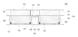
도 2는 본 발명의 일 실시예에 따른 액화천연가스 화물창의 단열구조를 절단한 단면도.
도 3은 본 발명의 일 실시예에 따른 앵커부재의 일 예를 나타낸 확대도.
도 4는 본 발명의 일 실시예에 따른 앵커부재의 다른 일 예를 나타낸 확대도.
도 5는 본 발명의 일 실시예에 따른 액화천연가스 화물창의 단열구조의 단면을 나타낸 사시도.
도 6은 본 발명의 일 실시예에 따른 액화천연가스 화물창의 단열구조 시공방법을 나타낸 도면.
도 7은 본 발명의 일 실시예에 따른 액화천연가스 화물창의 단열구조를 포함하는 선박을 나타낸 도면.1 is a cross-sectional view showing an insulating structure of the LNG cargo hold according to the prior art.
Figure 2 is a cross-sectional view cut the insulation structure of the LNG cargo hold according to an embodiment of the present invention.
Figure 3 is an enlarged view showing an example of an anchor member according to an embodiment of the present invention.
Figure 4 is an enlarged view showing another example of the anchor member according to an embodiment of the present invention.
Figure 5 is a perspective view showing a cross-section of the insulating structure of the LNG cargo hold according to an embodiment of the present invention.
Figure 6 is a view showing the construction method of the thermal insulation structure of the LNG cargo hold according to an embodiment of the present invention.
7 is a view showing a vessel including an insulating structure of the LNG cargo hold according to an embodiment of the present invention.
본 발명은 다양한 변환을 가할 수 있고 여러 가지 실시예를 가질 수 있는 바, 특정 실시예들을 도면에 예시하고 상세한 설명에 상세하게 설명하고자 한다. 그러나, 이는 본 발명을 특정한 실시 형태에 대해 한정하려는 것이 아니며, 본 발명의 사상 및 기술 범위에 포함되는 모든 변환, 균등물 내지 대체물을 포함하는 것으로 이해되어야 한다. 본 발명을 설명함에 있어서 관련된 공지 기술에 대한 구체적인 설명이 본 발명의 요지를 흐릴 수 있다고 판단되는 경우 그 상세한 설명을 생략한다.BRIEF DESCRIPTION OF THE DRAWINGS The present invention is capable of various modifications and various embodiments, and specific embodiments are illustrated in the drawings and described in detail in the detailed description. It is to be understood, however, that the invention is not to be limited to the specific embodiments, but includes all modifications, equivalents, and alternatives falling within the spirit and scope of the invention. DETAILED DESCRIPTION OF THE PREFERRED EMBODIMENTS Hereinafter, the present invention will be described in detail with reference to the accompanying drawings.
이하, 본 발명에 따른 액화천연가스 화물창의 단열구조와 그 시공방법 및 이를 포함하는 선박의 실시예를 첨부도면을 참조하여 상세히 설명하기로 하며, 첨부 도면을 참조하여 설명함에 있어, 동일하거나 대응하는 구성 요소는 동일한 도면번호를 부여하고 이에 대한 중복되는 설명은 생략하기로 한다.
Hereinafter, the insulating structure of the liquefied natural gas cargo hold according to the present invention and its construction method and an embodiment of the ship including the same will be described in detail with reference to the accompanying drawings, in the following description, the same or corresponding Components are assigned the same reference numerals and redundant description thereof will be omitted.
도 2는 본 발명의 일 실시예에 따른 액화천연가스 화물창의 단열구조를 절단한 단면도이고, 도 3은 본 발명의 일 실시예에 따른 앵커부재의 일 예를 나타낸 확대도이며, 도 4는 본 발명의 일 실시예에 따른 앵커부재의 다른 일 예를 나타낸 확대도이다. Figure 2 is a cross-sectional view of the insulating structure of the LNG cargo hold according to an embodiment of the present invention, Figure 3 is an enlarged view showing an example of an anchor member according to an embodiment of the present invention, Figure 4 An enlarged view showing another example of an anchor member according to an embodiment of the present invention.
본 발명의 일 실시예에 따른 액화천연가스 화물창의 단열구조(100)는, 액화천연가스 화물창(101)의 내벽에 부착되며, 상면에 앵커스트립(122)이 형성되는 앵커부재(120)와; 단열패널(134) 및 금속판(132)을 구비하며, 상기 액화천연가스 화물창(101)의 내벽에 부착되는 복수의 단위단열부재(130)를 포함할 수 있다.
여기서, 금속판(132)은 그 단부가 상기 단열패널(134)의 테두리에서 외측으로 돌출되어 앵커스트립(122) 상에 위치하도록 단열패널(134)의 일면에 부착될 수 있다. 또한, 서로 인접하는 단위단열부재(130)의 일면에 부착된 각각의 금속판(132)의 돌출 연장된 단부는, 상기 앵커스트립(122) 상에서 서로 겹쳐지도록 용접될 수 있다. Here, the
도 2에 도시된 바와 같이, 본 실시예에 따른 액화천연가스 화물창의 단열구조(100)에서는, 앵커부재(120)가 에폭시 글루와 같은 접착제 등에 의해 화물창(101)의 내벽에 부착될 수 있으며, 단위단열부재(130)가 액화천연가스 운반선의 화물창(101) 내벽에 에폭시 매스틱(102)과 스터드 볼트(104) 등에 의해 부착 고정될 수 있다. As shown in Figure 2, in the
여기서, 단위단열부재(130)는, 화물창(101) 내벽과 접하는 단위단열부재(130)의 타면에 접합되는 고정판(106)을 포함할 수 있다. 고정판(106)은, 에폭시 글루와 같은 접착제 등에 의해 단위단열부재(130)의 타면에 접합될 수 있다. Here, the
고정판(106)은, 단위단열부재(130)를 화물창(101) 내벽에 고정 부착하기 위한 판형의 부재로서, 플라이우드(plywood)와 같은 목재 재질로 형성될 수 있다 본 실시예에서는, 고정판(106)을 관통하는 스터드 볼트(104)의 일단부에 너트를 체결함으로써, 단위단열부재(130)를 화물창(101) 내벽에 고정 결합할 수 있다. The
즉, 화물창(101)의 내벽에 고정 결합된 스터드 볼트(104)의 일단부가 단위단열부재(130)의 고정판(106) 및 단열패널(134)을 관통하여 형성되는 삽입홀(108)에 삽입됨으로써, 너트를 상기 스터드 볼트(104)의 일단부에 체결하여 단위단열부재(130)를 화물창(101) 내벽에 고정 결합할 수 있다.That is, one end of the
비록 도시되지는 않았지만, 단위단열부재(130)는 이외에도 다양한 방식으로 액화천연가스 운반선의 화물창(101) 내벽에 부착 고정될 수 있음은 물론이다. Although not shown, the
도 3에 도시된 바와 같이, 앵커부재(120)는 서로 인접하는 단위단열부재(130) 사이에 개재되는 긴 막대형상의 단열부재로서, 단열재(124)와; 상기 단열재(124) 상면에 접합하는 절연층(126)을 포함하여 구성될 수 있다. 이때, 앵커스트립(122)은 절연층(126)의 상면에 일면이 노출되도록 매립될 수 있다. 예를 들면, 앵커스트립(122)의 일면은 절연층(126)의 상면과 동일 평면을 가지도록 형성될 수 있다.As shown in FIG. 3, the
단열재(124)는, 폴리우레탄 소재의 단열재로 형성될 수 있다. The
절연층(126)은, 단열재(124)의 상면에 형성되는 부재로서, 금속판(132) 용접 시 열전도를 차단하는 역할을 한다. 서로 인접한 금속판(132)의 각각의 단부들이 앵커스트립(122) 상에서 용접될 시 고온의 열에 의해 단열재(124)가 녹는 현상이 발생할 수 있는데, 절연층(126)을 단열재(124) 상면에 형성함으로써, 단열재(124)가 녹는 현상을 방지할 수 있다. The insulating
절연층(126)은, 절연성을 가지는 목재재질의 플라이우드(plywood)로 형성될 수 있다. 본 실시예에서는, 절연층(126)으로 열을 차단할 수 있는 플라이우드를 예로 들었으나, 이외에도 절연층(126)은 절연성뿐만 아니라 가볍고 고온에 견딜 수 있는 유리섬유 복합재(glass fiber reinforced composite) 혹은 카본섬유 복합재(Carbon fiber reinforced composite)로 형성될 수도 있다. The insulating
본 실시예에서는 도 3에 도시된 바와 같이 절연층(126)이 단열재(124)의 상면에 층을 형성하는 경우를 예로 들어 설명하였으나, 도 4에 도시된 바와 같이 앵커스트립(122)의 일면이 노출되도록 앵커스트립(122)을 감싸는 채널(channel) 형태를 가질 수도 있다.In this embodiment, as shown in FIG. 3, the insulating
앵커스트립(122)은, 일면이 노출되도록 절연층(126)의 상부에 매립되는 얇고 긴 판재 모양의 부재로서, 서로 인접하는 금속판(132)의 각각의 단부가 서로 겹쳐지게 배치되어 앵커스트립(122) 상에서 용접될 때, 금속판(132)의 단부들이 서로 용접될 수 있는 용접표면을 제공하는 역할을 한다. 이를 통해, 용접품질을 향상시킬 수 있으며 결과적으로 금속판(132)들이 연속적으로 용접되어 형성하는 2차 방벽의 기밀성을 향상시킬 수 있다. The
본 실시예에서는, 서로 인접하는 금속판(132)의 단부가 앵커스트립(122) 상에서 서로 겹쳐진 후 함께 용접되는 경우를 예로 들어 설명하였으나, 이외에도 서로 인접하는 금속판(132)의 단부 중 하나가 앵커스트립(122) 상면에 먼저 용접된 후 다른 하나가 그 위에 겹쳐져서 용접될 수도 있음은 물론이다. In the present embodiment, the ends of the
앵커스트립(122)은, 스테인리스 강(stainless steel), 알루미늄 합금, 인바(invar) 합금과 같은 금속재질로 이루어질 수 있다. 특히, 금속판(132)의 용접 시 용접성에 문제가 발생하는 것을 방지하기 위해, 앵커스트립(122)은 금속판(132)과 동일한 소재로 이루어질 수 있다. The
도 2에 도시된 바와 같이, 단위단열부재(130)는, 단열패널(134)과; 단부가 상기 단열패널(134)의 테두리에서 외측으로 돌출되어 상기 앵커스트립(122) 상에 위치하도록 상기 단열패널(134)의 상면에 접합되는 금속판(132)을 포함하여 구성될 수 있다. As shown in FIG. 2, the
단열패널(134)은, 박스 형태의 단열 판재로서, 고정판(106)의 일면에 접합될 수 있으며, 앞서 상술한 단열재(124)와 같은 폴리우레탄 소재의 단열재로 형성될 수 있다. The
금속판(132)은, 단열패널(134)의 테두리에서 외측으로 돌출되어 앵커부재(120)의 앵커스트립(122) 상에 위치하도록 단열패널(134)의 상면에 접합되는 금속 박막(metal foil)으로서, 액화천연가스 화물창의 단열구조(100)의 2차 방벽을 형성하게 된다. The
금속판(132)은, 평편하고 얇은 스테인리스 강, 알루미늄 합금, 인바 합금과 같은 금속재질로 이루어질 수 있다. The
본 실시예서는, 금속판(132)으로 두께가 0.7mm ~ 1.4mm 사이의 박막 금속판을 사용할 수 있다. In the present embodiment, a thin metal plate having a thickness of 0.7 mm to 1.4 mm may be used as the
금속판(132)의 두께가 1.4mm를 초과할 경우 금속판(132)의 자체 강성에 의하여 취급 및 가공이 어려운 문제점이 있다. 또한, 금속판(132)의 두께가 0.7mm보다 얇을 경우에는 금속판(132)의 자체 강성이 너무 약하여 취급 및 가공 시 어려움이 있으며, 금속판(132)들이 서로 용접결합되어 액화천연가스 화물창의 단열구조(100)의 2차 방벽을 형성하더라도 화물을 적재하고 운항 시 가해지는 외력 등에 의해 쉽게 파손되는 문제가 있다. When the thickness of the
금속판(132)은, 에폭시 글루 등과 같은 접착제에 의해 단열패널(134)의 상면에 접합될 수 있다. 이때, 접착 강도 향상을 위하여, 금속판(132)의 내벽은 먼저 프라이머(primer) 또는 실란(silane)으로 코팅 처리될 수 있다. The
또한, 금속판(132)이 단열패널(134) 및 후술할 상부 단열패널(140)과 더 강력하게 접합될 수 있도록 금속판(132)의 표면에 거칠기를 형성할 수도 있다. 즉, 금속판(132)의 표면에 거칠기를 형성함으로써, 접착 부위에서 발생할 수 있는 전단력에 대해 향상된 전단강도를 제공할 수 있다. 금속판(132)의 표면에 거칠기를 형성하기 위해 연마지가 사용될 수 있다. In addition, roughness may be formed on the surface of the
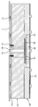
도 5는 본 실시예에 따른 액화천연가스 화물창의 단열구조(100)의 단위단열부재(130)를 절단한 단면을 나타낸 도면이다. 5 is a cross-sectional view of the
도 5에 도시된 바와 같이, 금속판(132)의 단부에는, 길이방향으로 주름부(136)가 형성될 수 있다. 주름부(136)는, 설계조건에 따라 오목하거나 볼록하게 형성될 수 있다. As shown in FIG. 5, at the end of the
본 실시예에서는, 주름부(136)가 금속판(132)의 테두리를 따라 하방향 또는 상방향으로 돌출되어 형성될 수 있으며, 금속판(132)에 가해지는 열수축 변위를 흡수하는 역할을 할 수 있다. 즉, 주름부(136)는, 열에 의한 팽창 및 수축을 흡수함으로써 금속판(132)의 열변형에 의한 기밀성 저하를 방지할 수 있다. In the present embodiment, the
따라서 본 발명에서는, 반복적인 열응력을 받을 경우, 내부 보강 섬유와 수지 간의 열팽창 계수 차이로 인하여 균열이 발생되고 이로 인해 가스 누설을 야기하는 복합재료인 트리플렉스 대신에, 금속판을 용접결합하고 금속판의 단부에는 주름부를 설치함으로써 열변형에 대응할 수 있고 2차 방벽의 기밀성을 유지할 수 있다. Therefore, in the present invention, when subjected to repeated thermal stress, cracks are generated due to the difference in coefficient of thermal expansion between the internal reinforcing fibers and the resin, and instead of the triplex, which is a composite material, which causes gas leakage, the metal sheets are welded and bonded to each other. By providing a pleat at the end, it is possible to cope with thermal deformation and to maintain the airtightness of the secondary barrier.
도 2에 도시된 바와 같이, 본 실시예에 따른 액화천연가스 화물창의 단열구조(100)는, 금속판(132)의 상면에 접합되는 상부 단열패널(140)을 더 포함할 수 있다. As shown in FIG. 2, the
여기서, 단열패널(134) 및 금속판(132)을 포함하는 단위단열부재(130)는, 미리 공장에서 상부 단열패널(140)과 서로 접합되어 하나의 단위체를 형성한 후, 화물창 내부에 설치될 수 있다. Here, the
상부 단열패널(140)은, 앞서 상술한 단열패널(134)과 동일 유사한 단열 판재로서, 금속판(132)의 상면에 접합될 수 있으며, 폴리우레탄 소재의 단열재로 형성될 수 있다. The upper
본 실시예에서는, 상부 단열패널(140)의 폭과 너비가 단열패널(134)의 폭과 너비에 비해 각각 작게 형성될 수 있다. 이는, 금속판(132)의 용접 시 작업공간을 제공함으로써 시공성을 향상시키기 위함이다. In this embodiment, the width and width of the
본 실시예에 따른 액화천연가스 화물창의 단열구조(100)는, 앵커스트립(122) 상에서 용접 결합된 금속판(132)의 단부 상에 위치하도록 인접한 두 상부 단열패널(140) 사이에 삽입되는 브리지 패널(150)을 더 포함할 수 있다. The
브리지 패널(150)은, 상부 단열패널(140)과 같은 폴리우레탄 소재의 단열재로 형성될 수 있으며, 인접하여 배치되는 두 상부 단열패널(140) 사이에 형성되는 빈 공간을 충진하는 역할을 한다. 브리지 패널(150)은, 앵커스트립(122) 상에서 용접 결합된 금속판(132)의 단부 상면에 에폭시 글루와 같은 접착제를 통해 부착될 수 있다. 이때, 금속판(132)의 단부 상면에 부착된 브리지 패널(150)의 상면은, 인접한 두 상부 단열패널(140)의 상면 각각과 동일 평면을 가지도록 형성될 수 있다. The
주름부(136)가 금속판(132)의 테두리를 따라 상방향으로 돌출되어 형성되는 경우, 브리지 패널(150)의 저면에는 주름부(136)를 수용하기 위한 홈(152)이 주름부(136)의 길이방향으로 형성될 수 있다. When the
이때, 홈(152)의 형상은, 금속판(132)의 주름부(136)가 삽입되어 수용될 수 있는 형상이면 무방하나, 단열재를 최대한 설치하기 위하여 주름부(136)와 최소한의 간격을 유지하며 주름부(136)에 대응되는 동일 또는 유사한 형상으로 형성될 수 있다. At this time, the shape of the
한편, 상부 단열패널(140)과 브리지 패널(150)의 상면에는 적재화물의 하중을 지지하기 위한 상부판재(미도시)가 형성될 수 있다. 상부판재(미도시)는, 플라이우드와 같은 목재로 형성될 수 있으며, 상부 단열패널(140)과 브리지 패널(150)의 상면에 에폭시 글루와 같은 접착제 등에 의해 접합될 수 있다. On the other hand, the upper surface of the
상부 단열패널(140)과 브리지 패널(150)의 상부에는, 멤브레인(160)을 부착하여 액화천연가스 화물창(100)의 단열구조를 완성할 수 있다. 멤브레인(160)은, 에폭시 글루와 같은 접착제 등에 의해 상부 단열패널(140)과 브리지 패널(150)의 상부에 동일한 평면을 이루도록 부착될 수 있다.A
멤브레인(160)은, 액화천연가스 화물창(100)의 단열구조에서 1차 방벽을 구성하는 부분으로 화물창의 기밀성을 유지하기 위해 금속재 시트로 형성될 수 있다. 멤브레인(160)은, 적재화물에 의한 온도변화에 대응하여 팽창 및 수축이 용이할 수 있도록 길이 또는 너비방향으로 주름이 형성된 스테인리스 강으로 이루어질 수 있다. The
이와 같이, 본 실시예에 따른 액화천연가스 화물창의 단열구조(100)에 따르면, 앵커스트립(122) 상에서 서로 겹쳐지는 금속판(132)의 단부를 서로 용접함으로써, 2차 방벽의 기밀성을 높임과 동시에 작업성을 향상시키고 시공기간을 단축시킬 수 있다.
As described above, according to the insulating
이상에서는 본 발명의 일 측면에 따른 액화천연가스 화물창의 단열구조(100)에 대해 설명하였으며, 이하에서는 상기 액화천연가스 화물창의 단열구조(100)를 시공하기 위한 본 발명의 다른 측면에 따른 액화천연가스 화물창의 단열구조 시공방법에 대해 설명하도록 한다. In the above description of the insulating
도 6은 본 발명의 일 실시예에 따른 액화천연가스 화물창의 단열구조 시공방법을 나타낸 순서도이다. Figure 6 is a flow chart illustrating a method for constructing a thermal insulation structure of a LNG cargo hold according to an embodiment of the present invention.
본 발명의 일 실시예에 따른 액화천연가스 화물창의 단열구조 시공방법은, 단열패널(134) 및 단부가 상기 단열패널(134)의 테두리에서 외측으로 돌출되도록 상기 단열패널(134)의 일면에 부착되는 금속판(132)을 구비하는 단위단열부재(130)를 제공하는 단계(S10); 상면에 앵커스트립(122)이 형성되는 앵커부재(120)를 액화천연가스 화물창(101)의 내벽에 부착하는 단계(S20); 상기 앵커스트립(122) 상에서 상기 금속판(132)의 단부가 서로 겹치도록 복수의 상기 단위단열부재(130)를 상기 액화천연가스 화물창(101)의 내벽에 부착하는 단계(S30); 및 상기 금속판(132)의 단부를 서로 용접하는 단계(S40)를 포함할 수 있다.Insulation structure construction method of the LNG cargo hold according to an embodiment of the present invention, the
본 실시예의 경우, 액화천연가스 화물창의 단열구조(100)에 대한 구성 및 작용은 전술한 실시예와 동일 또는 상응하므로 이에 대한 설명은 생략하기로 한다. In the case of the present embodiment, since the configuration and operation of the insulating
먼저, 화물창의 내벽에 복수의 단위단열부재를 부착하여 형성되는 액화 천연가스 화물창의 단열구조의 시공방법에 있어서, 단열패널(134) 및 금속판(132)을 포함하는 단위단열부재(130)를 제공할 수 있다(S10). 이때, 금속판(132)은 그 단부가 상기 단열패널(134)의 테두리에서 외측으로 돌출되도록 단열패널(134)의 일면에 부착될 수 있다. First, in the construction method of the insulating structure of the liquefied natural gas cargo hold formed by attaching a plurality of unit insulating members on the inner wall of the cargo hold, providing a
앞서 상술한 바와 같이, 단위단열부재(130)는, 단열패널(134)과; 상기 단열패널(134)의 테두리에서 외측으로 돌출되어 상기 앵커스트립(122) 상에 위치하도록 상기 단열패널(134)의 상면에 접합되는 금속판(132)을 포함하여 구성될 수 있다. As described above, the
또한, 금속판(132) 상면에는 상부 단열패널(140)이 부착될 수 있다. 즉, 본 실시예에 따른 단위단열부재(130)는, 단열패널(134)과, 단열패널(134)의 일면에 부착되는 금속판(132), 및 금속판(132)의 상면에 부착되는 상부 단열패널(140)을 포함하여 구성될 수 있다. In addition, the
즉, 단위단열부재(130)는, 단열패널(134)과 금속판(132) 및 상부 단열패널(140)이 일체(one body)로 형성된 부재로 이루어질 수 있다. That is, the
여기서, 단위단열부재(130)는, 미리 공장에서 상부 단열패널(140)과 서로 접합되어 하나의 단위체를 형성한 후, 화물창 내부에 설치될 수 있다. 이때, 단열패널(134) 및 상부 단열패널(140) 그리고 그 사이에 개재되는 금속판(132)은, 폴리우레탄 접착제 등에 의해 서로 접합될 수 있다. Here, the
다음으로, 상면에 앵커스트립(122)이 형성되는 앵커부재(120)를 액화천연가스 화물창(101)의 내벽에 부착할 수 있다(S20). 이때, 앵커부재(120)를 화물창(101)의 내벽에 선 시공한 후, 상기 앵커부재(120)를 사이에 두고 서로 인접하는 단위단열부재(130)를 내벽에 부착할 수 있다. Next, the
앵커부재(120)는 에폭시 글루와 같은 접착제 등에 의해 화물창(101)의 내벽에 부착될 수 있다. The
앞서 상술한 바와 같이, 앵커부재(120)는 서로 인접하는 단위단열부재(130) 사이에 개재되는 긴 막대형상의 단열부재로서, 단열재(124)와; 상기 단열재(124) 상면에 접합하는 절연층(126)과; 상기 절연층(126)의 상면에 일면이 노출되도록 매립되는 앵커스트립(122)을 포함하여 구성될 수 있다.As described above, the
다음으로, 인접하는 금속판(132)의 단부가 앵커스트립(122) 상에서 서로 겹치도록 복수의 단위단열부재(130)를 화물창(101)의 내벽에 부착할 수 있다(S30). 이때, 단위단열부재(130)는 화물창(101) 내벽에 에폭시 매스틱(102)과 스터드 볼트(104) 등에 의해 부착 고정될 수 있다. Next, the plurality of
도 3에 도시된 바와 같이, 앵커부재(120)를 사이에 두고 서로 인접하여 배치되는 단위단열부재(130)의 금속판(132)의 각각의 단부가, 앵커스트립(122) 상에서 서로 겹치지게 배치될 수 있다. As shown in FIG. 3, end portions of the
다음으로, 앵커스트립(122) 상에서 서로 겹쳐지는 금속판(132)의 단부를 서로 용접할 수 있다(S40). Next, the ends of the
앵커스트립(122) 상에서 서로 겹쳐지는 금속판(132)의 단부를 서로 용접함으로써, 2차 방벽을 형성하는 금속판(132)의 기밀성을 유지할 수 있다. By welding the ends of the
용접방식으로는, 미세 플라즈마 용접, 저항용접, 저출력 레이저용접, 초음파용접 등이 적용될 수 있다. As the welding method, fine plasma welding, resistance welding, low power laser welding, ultrasonic welding, or the like may be applied.
본 실시예에서는, 서로 인접하는 금속판(132)의 단부가 앵커스트립(122) 상에서 서로 겹쳐진 후 함께 용접되는 경우를 예로 들어 설명하였으나, 이외에도 서로 인접하는 금속판(132)의 단부 중 하나가 앵커스트립(122) 상면에 먼저 용접된 후 다른 하나가 그 위에 겹쳐져서 용접될 수도 있음은 물론이다. In the present embodiment, the ends of the
본 실시예에 따른 액화천연가스 화물창의 단열구조 시공방법은, 앵커스트립(122) 상에서 용접 결합된 금속판(132)의 단부 위에 위치하도록 인접한 두 상부 단열패널(140) 사이에 브리지 패널(150)을 삽입하는 단계(S50)를 더 포함할 수 있다.Insulating structure construction method of the LNG cargo hold according to the present embodiment, the
브리지 패널(150)은, 인접하여 배치되는 두 상부 단열패널(140) 사이에 형성되는 빈 공간을 충진하는 역할을 하며, 앵커스트립(122) 상에서 용접 결합된 금속판(132)의 단부 상면에 에폭시 글루와 같은 접착제를 통해 부착될 수 있다. The
이와 같이, 본 실시예에 따른 액화천연가스 화물창의 단열구조 시공방법에 따르면, 앵커스트립(122) 상에서 서로 겹쳐지는 금속판(132)의 단부를 서로 용접함으로써, 2차 방벽의 기밀성을 높임과 동시에 작업성을 향상시키고 시공기간을 단축시킬 수 있다.
As described above, according to the method for constructing the insulating structure of the LNG cargo hold according to the present embodiment, by welding the ends of the
이상에서는 본 발명의 다른 측면에 따른 액화천연가스 화물창 단열구조(100)의 시공방법에 대해 설명하였으며, 이하에서는 상기 액화천연가스 화물창의 단열구조(100)를 포함하는 본 발명의 또 다른 측면에 따른 선박(1000)에 대해 설명하도록 한다. In the above described the construction method of the liquefied natural gas cargo
도 7은 본 발명의 일 실시예에 따른 액화천연가스 화물창의 단열구조(100)를 포함하는 선박(1000)을 나타낸 도면이다. 7 is a view showing a
본 발명의 일 실시예에 따른 선박(1000)은, 선체(1)와; 상기 선체(1)에 구비된 액화천연가스 화물창(101)과; 상기 액화천연가스 화물창(101)에 설치된 단열구조(100)를 포함하여 구성될 수 있다.
본 실시예의 경우, 액화천연가스 화물창의 단열구조(100)에 대한 구성 및 작용은 전술한 실시예와 동일 또는 상응하므로 이에 대한 설명은 생략하기로 한다. In the case of the present embodiment, since the configuration and operation of the insulating
선체(1)는, 사람이나 화물 등을 싣고 수상을 항해하며 이들을 운반하는 구조물로서, 물위에 뜬다는 부양성과 사람이나 화물을 실을 수 있다는 적재성 및 적재된 것을 원하는 장소로 운반할 수 있는 이동성 등 기본 3요소를 갖춘 해상 구조물을 의미한다. The
본 명세서에서, "선박" 이라는 용어는 수상을 항해하는 구조물을 의미하는 것으로 한정되지 않으며, 수상을 항해하는 구조물뿐만 아니라, 수상에서 부유하며 작업을 수행하는 FLNG와 같은 해상 구조물 등을 포함하는 것으로 사용된다. 본 실시형태의 선박(1000)은 예를 들어 LNGC 또는 FLNG 일 수 있으나, 본 발명은 이에 제한되지 않는다.
In the present specification, the term "ship" is not limited to mean a structure that sails the water, but is used to include not only the structure that sails the water, but also a marine structure such as FLNG that floats and performs work in the water. do. The
상기에서는 본 발명의 실시예를 참조하여 설명하였지만, 해당 기술 분야에서 통상의 지식을 가진 자라면 하기의 특허 청구의 범위에 기재된 본 발명의 사상 및 영역으로부터 벗어나지 않는 범위 내에서 본 발명을 다양하게 수정 및 변경시킬 수 있음을 이해할 수 있을 것이다.Although the above has been described with reference to embodiments of the present invention, those skilled in the art may variously modify the present invention without departing from the spirit and scope of the present invention as set forth in the claims below. And can be changed.
전술한 실시예 외의 많은 실시예들이 본 발명의 특허청구범위 내에 존재한다.Many embodiments other than the above-described embodiments are within the scope of the claims of the present invention.
100 : 액화천연가스 화물창의 단열구조 101 : 화물창
102 : 에폭시 매스틱 104 : 스터드 볼트
106 : 고정판 120 : 앵커부재
122 : 앵커스트립 124 : 단열재
126 : 절연층 130 : 단위단열부재
132 : 금속판 134 : 단열패널
136 : 주름부 140 : 상부 단열패널
150 : 브리지 패널 152 : 홈
160 : 멤브레인 1000 : 선박100: liquefied natural gas cargo hold insulation structure 101: cargo hold
102: epoxy mastic 104: stud bolt
106: fixing plate 120: anchor member
122: anchor strip 124: insulation
126: insulating layer 130: unit insulation member
132: metal plate 134: insulation panel
136: wrinkles 140: upper insulation panel
150: bridge panel 152: groove
160: membrane 1000: ship
Claims (15)
상기 액화천연가스 화물창의 내벽에 부착되며, 상면에 앵커스트립이 형성되는 앵커부재; 및
단열패널 및 금속판을 구비하며, 상기 액화천연가스 화물창의 내벽에 부착되는 복수의 단위단열부재를 포함하되,
상기 금속판은 단부가 상기 단열패널의 테두리에서 외측으로 돌출되어 상기 앵커스트립 상에 위치하도록 상기 단열패널의 일면에 부착되며,
상기 금속판의 단부는 서로 상기 앵커스트립 상에서 용접되는 것을 특징으로 하는 액화천연가스 화물창의 단열구조.
As the insulation structure of LNG cargo hold,
An anchor member attached to an inner wall of the liquefied natural gas cargo hold and having an anchor strip formed on an upper surface thereof; And
It includes a heat insulation panel and a metal plate, and includes a plurality of unit insulation member attached to the inner wall of the liquefied natural gas cargo hold,
The metal plate is attached to one surface of the heat insulation panel so that an end portion protrudes outward from the edge of the heat insulation panel and located on the anchor strip.
End portions of the metal plate is insulated structure of the LNG cargo hold, characterized in that welded to each other on the anchor strip.
상기 금속판 상면에 접합되는 상부 단열패널을 더 포함하는 액화천연가스 화물창의 단열구조.
The method of claim 1,
The insulating structure of the LNG cargo hold further comprises an upper insulating panel bonded to the upper surface of the metal plate.
상기 앵커부재는,
단열재와;
상기 단열재 상면에 접합하는 절연층을 포함하며,
상기 앵커스트립은, 상기 절연층의 상면에 일면이 노출되도록 매립되는 것을 특징으로 하는 액화천연가스 화물창의 단열구조.
The method of claim 1,
The anchor member,
Insulation material;
An insulating layer bonded to the upper surface of the insulating material,
The anchor strip is a heat insulation structure of a LNG cargo hold, characterized in that the buried so that one surface is exposed on the upper surface of the insulating layer.
상기 절연층은,
플라이우드(plywood)로 형성되는 것을 특징으로 하는 액화천연가스 화물창의 단열구조.
The method of claim 3,
Wherein the insulating layer
Insulating structure of the LNG cargo hold, characterized in that formed of plywood (plywood).
상기 앵커스트립은,
스테인리스 강인 것을 특징으로 하는 액화천연가스 화물창의 단열구조.
The method of claim 3,
The anchor strip,
Insulating structure of LNG cargo hold, characterized in that stainless steel.
상기 금속판의 두께는 0.7mm 내지 1.4mm인 것을 특징으로 하는 액화천연가스 화물창의 단열구조.
The method of claim 1,
The thickness of the metal plate is a heat insulating structure of the LNG cargo hold, characterized in that 0.7mm to 1.4mm.
상기 금속판의 단부에는,
길이방향으로 주름부가 형성되는 것을 특징으로 하는 액화천연가스 화물창의 단열구조.
7. The method according to any one of claims 1 to 6,
At the end of the metal plate,
Insulating structure of the LNG cargo hold, characterized in that the corrugation is formed in the longitudinal direction.
단열패널 및 단부가 외측으로 돌출되도록 상기 단열패널의 일면에 부착되는 금속판을 구비하는, 단위단열부재를 제공하는 단계;
상면에 앵커스트립이 형성되는 앵커부재를 상기 액화천연가스 화물창의 내벽에 부착하는 단계;
상기 앵커스트립 상에서 상기 금속판의 단부가 서로 겹치도록 복수의 상기 단위단열부재를 상기 액화천연가스 화물창의 내벽에 부착하는 단계; 및
상기 금속판의 단부를 서로 용접하는 단계;를 포함하는 액화천연가스 화물창의 단열구조 시공방법.
As a method of constructing the insulation structure of LNG cargo hold,
Providing a unit insulation member having a heat insulation panel and a metal plate attached to one surface of the heat insulation panel so that the end portion protrudes outward;
Attaching an anchor member having an anchor strip formed on an upper surface thereof to an inner wall of the liquefied natural gas cargo hold;
Attaching the plurality of unit insulation members to the inner wall of the LNG cargo hold so that the ends of the metal plate overlap each other on the anchor strip; And
And welding the ends of the metal plate to each other.
상기 금속판 상면에는 상부 단열패널이 부착되는 것을 특징으로 하는 액화천연가스 화물창의 단열구조 시공방법.
9. The method of claim 8,
An upper insulation panel is attached to the upper surface of the metal plate, the insulation structure construction method of the LNG cargo hold.
상기 앵커부재는,
단열재와;
상기 단열재 상면에 접합하는 절연층을 포함하며,
상기 앵커스트립은, 상기 절연층의 상면에 일면이 노출되도록 매립되는 것을 특징으로 하는 액화천연가스 화물창의 단열구조 시공방법.
9. The method of claim 8,
The anchor member,
Insulation material;
An insulating layer bonded to the upper surface of the insulating material,
The anchor strip, the insulating structure construction method of the LNG cargo hold, characterized in that the buried so that one surface is exposed on the upper surface of the insulating layer.
상기 절연층은,
플라이우드로 형성되는 것을 특징으로 하는 액화천연가스 화물창의 단열구조 시공방법.
The method of claim 10,
Wherein the insulating layer
Method for constructing a thermal insulation structure of a LNG cargo hold, characterized in that formed by plywood.
상기 앵커스트립은,
스테인리스 강인 것을 특징으로 하는 액화천연가스 화물창의 단열구조 시공방법.
The method of claim 10,
The anchor strip,
Method for constructing a thermal insulation structure of LNG cargo hold, characterized in that the stainless steel.
상기 금속판의 두께는 0.7mm 내지 1.4mm인 것을 특징으로 하는 액화천연가스 화물창의 단열구조 시공방법.
9. The method of claim 8,
The thickness of the metal plate is 0.7mm to 1.4mm construction method of the insulating structure of the LNG cargo hold.
상기 금속판의 단부에는,
길이방향으로 주름부가 형성되는 것을 특징으로 하는 액화천연가스 화물창의 단열구조 시공방법.
The method according to any one of claims 8 to 13,
At the end of the metal plate,
Method for the insulation structure of the LNG cargo hold characterized in that the wrinkles are formed in the longitudinal direction.
상기 선체에 구비된 액화천연가스 화물창과;
상기 액화천연가스 화물창에 설치되는 상기 제1항 내지 제6항 중 어느 한 항에 따른 액화천연가스 화물창의 단열구조를 포함하는 선박.Hulls;
LNG cargo hold provided in the hull;
A ship comprising an insulating structure of the LNG cargo hold according to any one of claims 1 to 6 installed in the LNG cargo hold.
Priority Applications (1)
| Application Number | Priority Date | Filing Date | Title |
|---|---|---|---|
| KR1020110036809A KR101259059B1 (en) | 2011-04-20 | 2011-04-20 | Insulation structure of lng cargo tank, method for constructing the same and ship having the same |
Applications Claiming Priority (1)
| Application Number | Priority Date | Filing Date | Title |
|---|---|---|---|
| KR1020110036809A KR101259059B1 (en) | 2011-04-20 | 2011-04-20 | Insulation structure of lng cargo tank, method for constructing the same and ship having the same |
Publications (2)
| Publication Number | Publication Date |
|---|---|
| KR20120119065A true KR20120119065A (en) | 2012-10-30 |
| KR101259059B1 KR101259059B1 (en) | 2013-04-29 |
Family
ID=47286385
Family Applications (1)
| Application Number | Title | Priority Date | Filing Date |
|---|---|---|---|
| KR1020110036809A Expired - Fee Related KR101259059B1 (en) | 2011-04-20 | 2011-04-20 | Insulation structure of lng cargo tank, method for constructing the same and ship having the same |
Country Status (1)
| Country | Link |
|---|---|
| KR (1) | KR101259059B1 (en) |
Cited By (2)
| Publication number | Priority date | Publication date | Assignee | Title |
|---|---|---|---|---|
| KR20150028896A (en) * | 2013-09-06 | 2015-03-17 | 대우조선해양 주식회사 | Wrinkle-intensive membrane and cryogenic fluid storage tank using the same |
| KR20160015458A (en) * | 2014-07-30 | 2016-02-15 | 삼성중공업 주식회사 | Barriear sheet used for cargo and cargo for liguefied gas |
Families Citing this family (1)
| Publication number | Priority date | Publication date | Assignee | Title |
|---|---|---|---|---|
| KR102726448B1 (en) * | 2019-08-14 | 2024-11-05 | 한화오션 주식회사 | Structure of Anchor Strip for LNG Storage Tank |
Family Cites Families (3)
| Publication number | Priority date | Publication date | Assignee | Title |
|---|---|---|---|---|
| FR2781557B1 (en) | 1998-07-24 | 2000-09-15 | Gaz Transport & Technigaz | IMPROVEMENT FOR A WATERPROOF AND THERMALLY INSULATING TANK WITH PREFABRICATED PANELS |
| KR100751697B1 (en) | 2006-09-20 | 2007-08-23 | 현대중공업 주식회사 | Insulation structure of cargo hold for LM storage containers using carbon fiber reinforced polymer (CFP) |
| KR200441261Y1 (en) * | 2007-08-14 | 2008-08-04 | 삼성중공업 주식회사 | Insulation panel safety device |
-
2011
- 2011-04-20 KR KR1020110036809A patent/KR101259059B1/en not_active Expired - Fee Related
Cited By (2)
| Publication number | Priority date | Publication date | Assignee | Title |
|---|---|---|---|---|
| KR20150028896A (en) * | 2013-09-06 | 2015-03-17 | 대우조선해양 주식회사 | Wrinkle-intensive membrane and cryogenic fluid storage tank using the same |
| KR20160015458A (en) * | 2014-07-30 | 2016-02-15 | 삼성중공업 주식회사 | Barriear sheet used for cargo and cargo for liguefied gas |
Also Published As
| Publication number | Publication date |
|---|---|
| KR101259059B1 (en) | 2013-04-29 |
Similar Documents
| Publication | Publication Date | Title |
|---|---|---|
| KR101345809B1 (en) | Insulation structure of lng cargo tank and method for constructing the same | |
| KR102387173B1 (en) | Insulation structure of 90 degree corner in liquefied gas cargo tank, and cargo tank having the insulation structure | |
| KR20120135494A (en) | Lng cargo insulation system | |
| KR101784833B1 (en) | Cargo for liquefied gas and fixing unit for paner used therein | |
| KR101792482B1 (en) | Cargo for liquefied gas and fixing unit for paner used therein | |
| KR101722370B1 (en) | Cargo barrier structure | |
| KR20120135475A (en) | Insulation structure for cargo hold of lng carrier | |
| KR101625871B1 (en) | Cargo for liquefied gas and manufacturing method thereof | |
| KR101259059B1 (en) | Insulation structure of lng cargo tank, method for constructing the same and ship having the same | |
| KR101225168B1 (en) | Insulation structure of lng cargo tank and ship having the same | |
| KR101444370B1 (en) | Insulation strusture to lng carrier cargo | |
| KR101824428B1 (en) | Cargo for liquefied gas | |
| KR101644354B1 (en) | Cargo barrier structure | |
| KR102778405B1 (en) | Insulation System of Liquefied Gas Storage Tank | |
| KR20160015437A (en) | Cargo for liquefied gas | |
| KR101422517B1 (en) | Cargo for liquefied gas carrier ship and manufacturing method thereof | |
| KR101672209B1 (en) | Cargo for liquefied natural gas | |
| KR101434146B1 (en) | Connecting structure of insulating barrier | |
| KR101302213B1 (en) | Insulation structure of lng cargo tank | |
| KR101625867B1 (en) | Cargo for liquefied gas and manufacturing method thereof | |
| KR102883954B1 (en) | Insulation system of liquefied gas storage tank | |
| KR20170114001A (en) | Lng cargo and construction method for the same | |
| KR20160043162A (en) | Cargo barrier structure | |
| KR101864152B1 (en) | Cargo for liquefied gas | |
| KR101487674B1 (en) | Cargo barrier structure |
Legal Events
| Date | Code | Title | Description |
|---|---|---|---|
| A201 | Request for examination | ||
| PA0109 | Patent application |
St.27 status event code: A-0-1-A10-A12-nap-PA0109 |
|
| PA0201 | Request for examination |
St.27 status event code: A-1-2-D10-D11-exm-PA0201 |
|
| PN2301 | Change of applicant |
St.27 status event code: A-3-3-R10-R13-asn-PN2301 St.27 status event code: A-3-3-R10-R11-asn-PN2301 |
|
| PN2301 | Change of applicant |
St.27 status event code: A-3-3-R10-R13-asn-PN2301 St.27 status event code: A-3-3-R10-R11-asn-PN2301 |
|
| E902 | Notification of reason for refusal | ||
| PE0902 | Notice of grounds for rejection |
St.27 status event code: A-1-2-D10-D21-exm-PE0902 |
|
| PG1501 | Laying open of application |
St.27 status event code: A-1-1-Q10-Q12-nap-PG1501 |
|
| P11-X000 | Amendment of application requested |
St.27 status event code: A-2-2-P10-P11-nap-X000 |
|
| P13-X000 | Application amended |
St.27 status event code: A-2-2-P10-P13-nap-X000 |
|
| E701 | Decision to grant or registration of patent right | ||
| PE0701 | Decision of registration |
St.27 status event code: A-1-2-D10-D22-exm-PE0701 |
|
| R18-X000 | Changes to party contact information recorded |
St.27 status event code: A-3-3-R10-R18-oth-X000 |
|
| GRNT | Written decision to grant | ||
| PR0701 | Registration of establishment |
St.27 status event code: A-2-4-F10-F11-exm-PR0701 |
|
| PR1002 | Payment of registration fee |
St.27 status event code: A-2-2-U10-U11-oth-PR1002 Fee payment year number: 1 |
|
| PG1601 | Publication of registration |
St.27 status event code: A-4-4-Q10-Q13-nap-PG1601 |
|
| R18-X000 | Changes to party contact information recorded |
St.27 status event code: A-5-5-R10-R18-oth-X000 |
|
| R18-X000 | Changes to party contact information recorded |
St.27 status event code: A-5-5-R10-R18-oth-X000 |
|
| PN2301 | Change of applicant |
St.27 status event code: A-5-5-R10-R13-asn-PN2301 St.27 status event code: A-5-5-R10-R11-asn-PN2301 |
|
| PR1001 | Payment of annual fee |
St.27 status event code: A-4-4-U10-U11-oth-PR1001 Fee payment year number: 4 |
|
| R18-X000 | Changes to party contact information recorded |
St.27 status event code: A-5-5-R10-R18-oth-X000 |
|
| P22-X000 | Classification modified |
St.27 status event code: A-4-4-P10-P22-nap-X000 |
|
| PR1001 | Payment of annual fee |
St.27 status event code: A-4-4-U10-U11-oth-PR1001 Fee payment year number: 5 |
|
| PR1001 | Payment of annual fee |
St.27 status event code: A-4-4-U10-U11-oth-PR1001 Fee payment year number: 6 |
|
| FPAY | Annual fee payment |
Payment date: 20190329 Year of fee payment: 7 |
|
| PR1001 | Payment of annual fee |
St.27 status event code: A-4-4-U10-U11-oth-PR1001 Fee payment year number: 7 |
|
| P22-X000 | Classification modified |
St.27 status event code: A-4-4-P10-P22-nap-X000 |
|
| PC1903 | Unpaid annual fee |
St.27 status event code: A-4-4-U10-U13-oth-PC1903 Not in force date: 20200424 Payment event data comment text: Termination Category : DEFAULT_OF_REGISTRATION_FEE |
|
| PN2301 | Change of applicant |
St.27 status event code: A-5-5-R10-R13-asn-PN2301 St.27 status event code: A-5-5-R10-R11-asn-PN2301 |
|
| PC1903 | Unpaid annual fee |
St.27 status event code: N-4-6-H10-H13-oth-PC1903 Ip right cessation event data comment text: Termination Category : DEFAULT_OF_REGISTRATION_FEE Not in force date: 20200424 |
|
| P22-X000 | Classification modified |
St.27 status event code: A-4-4-P10-P22-nap-X000 |