KR20120126257A - A coupler for connecting drain pipe - Google Patents
A coupler for connecting drain pipe Download PDFInfo
- Publication number
- KR20120126257A KR20120126257A KR1020110043914A KR20110043914A KR20120126257A KR 20120126257 A KR20120126257 A KR 20120126257A KR 1020110043914 A KR1020110043914 A KR 1020110043914A KR 20110043914 A KR20110043914 A KR 20110043914A KR 20120126257 A KR20120126257 A KR 20120126257A
- Authority
- KR
- South Korea
- Prior art keywords
- sewer pipe
- pipe
- locking
- connector
- jaw
- Prior art date
- Legal status (The legal status is an assumption and is not a legal conclusion. Google has not performed a legal analysis and makes no representation as to the accuracy of the status listed.)
- Granted
Links
Images


Classifications
-
- E—FIXED CONSTRUCTIONS
- E03—WATER SUPPLY; SEWERAGE
- E03F—SEWERS; CESSPOOLS
- E03F3/00—Sewer pipe-line systems
- E03F3/04—Pipes or fittings specially adapted to sewers
-
- E—FIXED CONSTRUCTIONS
- E03—WATER SUPPLY; SEWERAGE
- E03F—SEWERS; CESSPOOLS
- E03F3/00—Sewer pipe-line systems
- E03F3/06—Methods of, or installations for, laying sewer pipes
-
- F—MECHANICAL ENGINEERING; LIGHTING; HEATING; WEAPONS; BLASTING
- F16—ENGINEERING ELEMENTS AND UNITS; GENERAL MEASURES FOR PRODUCING AND MAINTAINING EFFECTIVE FUNCTIONING OF MACHINES OR INSTALLATIONS; THERMAL INSULATION IN GENERAL
- F16L—PIPES; JOINTS OR FITTINGS FOR PIPES; SUPPORTS FOR PIPES, CABLES OR PROTECTIVE TUBING; MEANS FOR THERMAL INSULATION IN GENERAL
- F16L41/00—Branching pipes; Joining pipes to walls
- F16L41/08—Joining pipes to walls or pipes, the joined pipe axis being perpendicular to the plane of a wall or to the axis of another pipe
- F16L41/14—Joining pipes to walls or pipes, the joined pipe axis being perpendicular to the plane of a wall or to the axis of another pipe by screwing an intermediate part against the inside or outside of the wall
Landscapes
- Health & Medical Sciences (AREA)
- Life Sciences & Earth Sciences (AREA)
- Engineering & Computer Science (AREA)
- Hydrology & Water Resources (AREA)
- Public Health (AREA)
- Water Supply & Treatment (AREA)
- Sewage (AREA)
Abstract
본 발명은 연결구 본체의 양측의 중간과 연결 하수관의 전방 단부면을 일치시킴에 따라 연결 하수관으로 부터 유입되는 하수의 흐름을 원활히 할 수 있는 하수관 연결구에 관한 것이다.
그리고 본 발명의 하수관 연결구는, 삽입관의 전방단부의 둘레에는 외측 걸림턱이 형성되고 삽입관의 외주면에는 삽입 걸림부가 구비된 연결구 본체와, 상기 삽입관에 삽입되고 내주면에는 상기 삽입 걸림부에 걸려 고정되는 걸림 고정부가 구비되어 있는 고정링과, 상기 삽입관을 연결 하수관에 고정하는 밴드 클램프와, 상기 고정링을 삽입관에 고정하는 밴드 클램프를 포함하는 하수관 연결구에 있어서; 상기 삽입관의 내주면의 전방 상,하부에는 연결 하수관의 삽입을 단속하는 내측 돌출턱이 형성되고, 상기 상,하부의 내측 돌출턱의 사이인 삽입관의 내주면 전방의 양측에는 개방부가 형성되며, 상기 연결구 본체의 전방 단부의 양측의 중간은 상기 연결 하수관의 전방 단부면과 일치되게 상기 내측 돌출턱의 후면과 일치되는 깊이로 함몰되게 형성되고, 상기 상,하부의 내측 돌출턱의 둘레 모서리부에는 전방으로 상향지고 전방으로 하향진 배수 경사면이 각각 형성되어 있는 것을 특징으로 한다. The present invention relates to a sewer pipe connector that facilitates the flow of sewage flowing from the connection sewer pipe by matching the middle of both sides of the connector body with the front end face of the connection sewer pipe.
And the sewer pipe connector of the present invention, the outer peripheral end of the insertion pipe is formed around the front end of the insertion pipe and the connector main body is provided with an insertion locking portion on the outer peripheral surface of the insertion pipe, and inserted into the insertion pipe and the inner peripheral surface is caught in the insertion locking portion In the sewer pipe connector comprising a fixing ring having a locking fixing portion to be fixed, a band clamp for fixing the insertion pipe to the connection sewer pipe, and a band clamp for fixing the fixing ring to the insertion pipe; An inner protrusion jaw is formed on the front upper and lower portions of the inner circumferential surface of the insertion tube to control the insertion of the connection sewer pipe, and an opening is formed on both sides of the inner circumferential surface front of the insertion tube between the upper and lower inner protrusion jaws. The middle of both sides of the front end of the connector body is formed to be recessed to a depth corresponding to the rear surface of the inner projection jaw to coincide with the front end surface of the connection sewer pipe, and the front and rear peripheral edges of the upper and lower inner projection jaw It is characterized in that the drain slope inclined upwardly and forwardly formed respectively.
Description
본 발명은 하수관 연결구에 관한 것으로, 보다 상세하게는, 연결구 본체의 양측의 중간과 연결 하수관의 전방 단부면을 일치시킴에 따라 연결 하수관으로 부터 유입되는 하수의 흐름을 원활히 할 수 있는 하수관 연결구에 관한 것이다.
The present invention relates to a sewer pipe connector, and more particularly, to a sewer pipe connector that can facilitate the flow of sewage flowing from the connection sewer pipe by matching the middle of both sides of the connector body and the front end surface of the connection sewer pipe. will be.
일반적으로 하수관은 콘크리트 옹벽으로 이루어진 지하시설물로서의 하수관과, 필요에 의해 교체하거나 보수할 수 있는 하수관으로 구분할 수 있으며, 이러한 하수관은 사람이 사용하고 버리는 생활하수를 일정한 장소 즉, 생활하수를 정화하는 하수정화처리장으로 흘러갈 수 있도록 지하에 매설하는 관을 지칭하는 것이다.In general, sewage pipes can be divided into sewage pipes as underground facilities consisting of concrete retaining walls, and sewage pipes that can be replaced or repaired as necessary. It refers to a pipe buried underground to flow to the purification plant.
이와 같이 하수관이 지하에 매설되어 있는 상태에서 주변에 사람이 거주하고 생활하는 새로운 건축물(주택이나 빌딩)을 건축할 경우에 주변에 매설되어 있는 하수관에 새로운 하수관을 연결하게 된다.
In this way, when a sewer is buried underground, when a new building (house or building) is inhabited and lived around it, a new sewer pipe is connected to the sewer pipe buried nearby.
따라서, 종래 지하에 매설된 하수관(이하, "주하수관" 이라 한다)에 새로운 하수관(이하, "연결 하수관"이라 한다.)을 연결시킬 경우, 주하수관의 외주면에 연결 하수관의 직경보다 같거나 크게 구멍을 뚫고 연결 하수관의 일단을 주하수관의 내측으로 끼워 넣고 그 주변에 시멘트몰탈을 덮어 연결 하수관을 연결시켰다.Therefore, when a new sewer pipe (hereinafter referred to as a "connected sewer pipe") is connected to a sewer pipe (hereinafter referred to as "main sewer pipe") buried underground, the diameter of the sewer pipe connected to the outer circumferential surface of the main sewer pipe is greater than or equal to the diameter of the sewer pipe. A hole was drilled and one end of the connecting sewage pipe was inserted into the inner side of the main sewage pipe, and the connecting sewage pipe was connected by covering the cement mortar with the periphery thereof.
그러나 상기와 같이 시멘트 몰탈을 덮는 방법으로 연결 하수관을 주하수관에 연결시킨 후, 연결 하수관과 주하수관을 흙으로 덮는 과정에서는 외부의 충격으로 인하여 시멘트 몰탈 부분에 손상이 발생되는 문제점을 가지고 있었다.
However, after connecting the connection sewer pipe to the main sewer pipe by covering the cement mortar as described above, in the process of covering the connection sewer pipe and the main sewer pipe with soil had a problem that damage to the cement mortar part due to external impact.
이에, 상기와 같은 문제점을 해소하기 위하여 본 출원인이 출원하여 등록받은 대한민국 등록실용신안 제299981호의 "하수관 연결구"(이하, "종래의 하수관 연결구"라 한다.)가 알려져 있다. Accordingly, in order to solve the above problems, the "sewer pipe connector" (hereinafter, referred to as "a conventional sewage pipe connector") of the Republic of Korea Registered Utility Model No. 299981 registered and applied by the applicant is known.
즉 종래의 하수관 연결관은, 연결구본체와 고정환으로 연결구가 이루어지되, 상기 연결구본체는 하단부에 외측으로 돌출한 외측걸림턱과 내측으로 돌출한 내측걸림턱을 형성하고, 하부에 길이방향의 수축홈을 등간격으로 다수 형성하며, 하부 내측면에 보강링이 갖춰지고, 상부 외면에 일방향(상방향)으로 경사면을 갖춘 랙(rack)형상의 상방향걸림부를 형성하고, 상기 외측걸림턱의 상면은 주하수관의 내경 곡면과 일치하는 곡면부를 이루며, 상기 보강링은 상단부의 링과 그 하측의 보강판으로 이루어지고, 상기 보강판은 링과 일체를 이루며, 내측으로 돌출한 탄성판을 등간격으로 다수 형성하고, 보강판의 하단부를 내측으로 절곡하여 지지단을 형성하며, 상기 고정환은 내면에 일방향(하방향)으로 경사면을 갖춘 랙형상의 하방향걸림부를 형성한 것을 특징으로 한다.
That is, the conventional sewer pipe connection, the connector is made of the connector and the fixed ring, the connector body is formed in the lower end of the outer engaging projection protruding outward and the inner engaging projection protruding inward, the longitudinal shrinkage groove in the lower portion It is formed a plurality of at equal intervals, the lower inner surface is provided with a reinforcing ring, the upper outer surface to form a rack-shaped upper engaging portion having a slope in one direction (upward direction), the upper surface of the outer locking jaw The reinforcing ring is composed of a ring at the upper end and a reinforcing plate at the lower side thereof, and the reinforcing plate is integral with the ring, and a plurality of elastic plates protruding inward are provided at equal intervals. Forming, bending the lower end of the reinforcing plate to the inner side to form a support end, wherein the fixed ring is formed on the inner surface of the rack-shaped down engaging portion having an inclined surface in one direction (downward direction) .
그런데, 상기와 같이 구성된 종래의 하수관 연결구는, 연결구본체의 내부 하단부에 형성된 내측걸림턱이 연결구본체의 내측 둘레에 전체적으로 돌출되게 형성됨으로써, 주 하수관에 연결된 연결 하수관의 양측에 단차가 지게됨에 따라 하수의 흐름이 원활하지 않는 문제점을 가지고 있었다. By the way, the conventional sewage pipe connector configured as described above, the inner catching jaw formed in the inner lower end of the connector main body is formed to protrude entirely around the inner circumference of the connector main body, so that the step is connected to both sides of the connection sewer pipe connected to the main sewer pipe Had a problem that the flow is not smooth.
또한 내측 걸림턱의 내측 둘레의 단부가 직각으로 형성됨에 따라, 연결하수관으로 부터 주 하수관으로 하수가 유입되는 과정에서 상기 내측 걸림터의 직각 단부에 하수에 포함된 이물질이 끼게 됨으로써, 시간이 흐를수록 하수의 흐름이 나빠지는 문제점도 가지고 있었다.
In addition, as the end portion of the inner circumference of the inner locking jaw is formed at right angles, foreign matter contained in the sewage is trapped at the right angled end of the inner locking ground in the process of flowing sewage from the connecting sewer pipe into the main sewer pipe. The sewage flow was also bad.
본 발명은 상기와 같은 문제점을 해소하기 위하여 안출된 것으로,The present invention has been made to solve the above problems,
본 발명의 목적은, 연결구 본체의 양측의 중간과 연결 하수관의 전방 단부면을 일치시킴으로써, 연결 하수관으로 부터 유입되는 하수의 흐름을 원활히 할 수 있도록 하는 하수관 연결구를 제공함에 있다. It is an object of the present invention to provide a sewer pipe connector that facilitates the flow of sewage flowing from a connection sewer pipe by matching the middle of both sides of the connector body with the front end face of the connection sewer pipe.
또한, 본 발명의 다른 목적은, 연결구 본체의 내주면의 전방 상,하부에 형성된 내측걸림턱의 모서리부에 함몰된 배수 경사면을 더 형성함으로써, 연결 하수관에서 유입되는 하수에 포함된 찌꺼기가 내측 걸림턱에 잔류되는 것을 방지할 수 있는 하수관 연결구를 제공함에 있다.In addition, another object of the present invention, by further forming a drain inclined surface recessed in the corner portion of the inner locking jaw formed in the front upper, lower portion of the inner circumferential surface of the connector body, the waste contained in the sewage flowing from the connection sewer pipe inside the locking jaw It is to provide a sewer pipe connection that can prevent the remaining in.
또한, 본 발명의 또 다른 목적은, 연결구본체를 구성하는 삽입관의 외주면의 전방둘레에 주 하수관의 관통홀의 둘레면이 밀착되는 수밀링부를 더 형성함으로써, 주 하수관의 관통홀과 연결구본체의 밀봉력을 향상시킬 수 있도록 하는 하수구 연결구를 제공함에 있다. Further, another object of the present invention is to seal the through hole of the main sewage pipe and the connector body by further forming a water sealing part in which the circumferential surface of the through hole of the main sewage pipe is in close contact with the front circumference of the outer circumferential surface of the insertion pipe constituting the connector main body. It is to provide a sewer connector to improve the power.
또한, 본 발명의 또 다른 목적은, 연결구 본체를 구성하는 삽입관의 후방에 고정링을 후방에서 전방으로 슬라이딩되게 삽입한 후, 일정각도의 회전만을 통해 삽입관에 고정링을 신속하면서도 용이하게 고정할 수 있도록 하는 하수관 연결구를 제공함에 있다. In addition, another object of the present invention, after inserting the fixed ring to the rear of the insertion tube constituting the connector body to slide from the rear to the front, and fast and easy to fix the fixing ring to the insertion tube only through the rotation of a certain angle. To provide a sewer pipe connection that allows it.
상기와 같은 목적을 달성하기 위한 본 발명은, 삽입관의 전방단부의 둘레에는 외측 걸림턱이 형성되고 삽입관의 외주면에는 삽입 걸림부가 구비된 연결구 본체와, 상기 삽입관에 삽입되고 내주면에는 상기 삽입 걸림부에 걸려 고정되는 걸림 고정부가 구비되어 있는 고정링과, 상기 삽입관을 연결 하수관에 고정하는 밴드 클램프와, 상기 고정링을 삽입관에 고정하는 밴드 클램프를 포함하는 하수관 연결구에 있어서; 상기 삽입관의 내주면의 전방 상,하부에는 연결 하수관의 삽입을 단속하는 내측 돌출턱이 형성되고, 상기 상,하부의 내측 돌출턱의 사이인 삽입관의 내주면 전방의 양측에는 개방부가 형성되며, 상기 연결구 본체의 전방 단부의 양측의 중간은 상기 연결 하수관의 전방 단부면과 일치되게 상기 내측 돌출턱의 후면과 일치되는 깊이로 함몰되게 형성되고, 상기 상,하부의 내측 돌출턱의 둘레 모서리부에는 전방으로 상향지고 전방으로 하향진 배수 경사면이 각각 형성되어 있는 것을 특징으로 한다. The present invention for achieving the above object, the outer end of the insertion tube is formed in the outer engaging jaw and the outer peripheral surface of the insertion tube is provided with a connector body, and the insertion tube is inserted into the insertion tube and the inner peripheral surface is inserted In the sewer pipe connector comprising a fixing ring having a locking fixing portion is fixed to the locking portion, a band clamp for fixing the insertion pipe to the connection sewer pipe, and a band clamp for fixing the fixing ring to the insertion pipe; An inner protrusion jaw is formed on the front upper and lower portions of the inner circumferential surface of the insertion tube to control the insertion of the connection sewer pipe, and an opening is formed on both sides of the inner circumferential surface front of the insertion tube between the upper and lower inner protrusion jaws. The middle of both sides of the front end of the connector body is formed to be recessed to a depth corresponding to the rear surface of the inner projection jaw to coincide with the front end surface of the connection sewer pipe, and the front and rear peripheral edges of the upper and lower inner projection jaw It is characterized in that the drain slope inclined upwardly and forwardly formed respectively.
또한, 상기 개방부는, 상,하부에 형성된 상기 상,하 내측돌출턱의 단부턱을 포함하여 단부턱의 사이에 형성되는 것을 특징으로 한다.In addition, the opening is characterized in that formed between the end jaw, including the end jaw of the upper, lower inner projection jaw formed in the upper, lower portion.
또한, 상기 삽입관의 외주면의 전방 둘레인 상기 외측 돌출턱의 후방에는, 주 하수관의 관통홀의 둘레 단부면과 밀착되는 수밀링이 접착이나 열융착에 의해 더 구비되어 있는 것을 특징으로 한다. In addition, the rear of the outer protruding jaw, which is the front circumference of the outer circumferential surface of the insertion pipe, is characterized in that the water-sealing is in close contact with the circumferential end surface of the through hole of the main sewer pipe is further provided by adhesion or heat fusion.
또한, 상기 삽입 걸림부는, 링 삽입홈부와 걸림랙부가 등간격의 교호 형성되어 구성되고; 상기 걸림 고정부는, 상기 걸림랙부가 전방에서 후방으로 삽입되는 관 삽입홈부와 상기 링 삽입홈부에 후방에서 전방으로 삽입되어 회전에 의해 상기 걸림랙부에 걸리는 고정랙부가 등간격의 교호로 형성되어 구성되는 것을 특징으로 한다. In addition, the insertion locking portion, the ring insertion groove portion and the locking rack portion is formed by alternating formation of equal intervals; The locking fixing portion is formed by the tube inserting groove portion into which the locking rack portion is inserted from the front and the ring insertion groove portion is inserted into the ring insertion groove from the rear to the front and the fixed rack portion to be caught by the locking rack at equal intervals. It is characterized by.
또한, 상기 걸림랙부는, 전방 수직단부와 전방 수직단부의 상부에서 후방으로 하향지게 형성된 후방 경사단부로 구성된 다수의 톱니가 다수 열로 형성되어 구성되고; 상기 고정랙부는, 후방 수직단부와 후방 수직단부의 상부에서 전방으로 하향지게 형성된 전방 경사단부로 구성된 다수의 톱니가 다수 열로 형성되어 구성되는 것을 특징으로 한다.
In addition, the locking rack portion is composed of a plurality of teeth formed of a plurality of teeth consisting of a front inclined end portion and a rear inclined end formed downward from the upper vertical end portion; The fixed rack portion is characterized in that a plurality of teeth formed of a plurality of teeth consisting of a front inclined end portion formed downward from the upper vertical rear portion and the rear vertical end portion forward.
상술한 바와 같은 본 발명은, 연결구 본체의 양측의 중간과 연결 하수관의 전방 단부면을 일치시킴에 따라, 연결 하수관으로 부터 유입되는 하수의 흐름을 원활히 함으로써, 우수시 하수의 흐름 적체로 인하여 발생되는 하수구의 역류현상을 사전에 예방하는 효과가 있다. The present invention as described above, by matching the middle of the both sides of the connector body and the front end surface of the connecting sewer pipe, by smoothing the flow of sewage flowing from the connecting sewer pipe, which is generated due to the flow of sewage during rain It is effective to prevent the backflow of sewers in advance.
또한, 연결부 본체의 내주연의 전방 상,하부에 구비된 내측걸림턱의 모서리부에 함몰된 배수 경사면을 더 형성함에 따라, 연결 하수관에서 유입되는 하수에 포함된 찌꺼기가 내측 걸림턱에 잔류되는 것을 방지함으로써, 시간이 경과되어 연결 하수관이 막히는 현상을 사전에 예방하는 효과도 있다. In addition, by further forming a drain inclined surface recessed at the corners of the inner locking jaw provided in the front upper and lower portions of the inner periphery of the connecting portion main body, the residue contained in the sewage flowing from the connecting sewage pipe remains in the inner locking jaw. By preventing it, there is also an effect of preventing the phenomenon that the connection sewer pipe is clogged over time.
또한, 연결구 본체를 구성하는 삽입관의 외주면의 전방둘레에 주 하수관에 형성된 관통홀의 둘레면이 밀착되는 수밀링부를 더 형성하여 주 하수관의 관통홀과 연결구 본체의 밀봉력을 향상시킴으로써, 장기간 동안 사용하더라도 누수를 방지하는 효과도 있다. In addition, by forming a water-tightening portion in which the circumferential surface of the through hole formed in the main sewer pipe is in close contact with the front circumference of the outer circumferential surface of the insertion pipe constituting the connector body to improve the sealing force of the through hole of the main sewer pipe and the connector body, for long-term use Even if it has the effect of preventing leakage.
또한, 일정각도의 회전만을 통해 삽입관에 고정링을 신속하면서도 용이하게 고정할 수 있도록 함으로써, 시공성을 향상시킨 하수관 연결구를 제공하는 효과도 있다.
In addition, by being able to quickly and easily fix the fixing ring to the insertion pipe only by a certain angle of rotation, there is also an effect of providing a sewer pipe connector with improved workability.
도 1은 본 발명의 하수관 연결구의 설치 상태를 나타낸 후방에서 본 분해사시도.
도 2는 본 발명에 따른 연결구 본체를 확대도시한 일부 절개사시도.
도 3은 본 발명의 하수관 연결구의 조립상태를 나타낸 종단면도.
1 is an exploded perspective view seen from the rear showing the installation state of the sewer pipe connector of the present invention.
Figure 2 is a partially cut perspective view showing an enlarged connector body according to the present invention.
Figure 3 is a longitudinal sectional view showing the assembled state of the sewer pipe connector of the present invention.
이하, 본 발명을 첨부된 도면에 의거하여, 보다 구체적으로 설명한다. 다만, 첨부된 도면은 본 발명의 기술사상을 보다 상세하게 설명하기 위한 것일 뿐이며, 본 발명의 기술사상이 이에 한정되는 것이 아님은 당연하다.
Hereinafter, with reference to the accompanying drawings, the present invention will be described in more detail. However, the accompanying drawings are only intended to describe the technical spirit of the present invention in more detail, and the technical spirit of the present invention is not limited thereto.
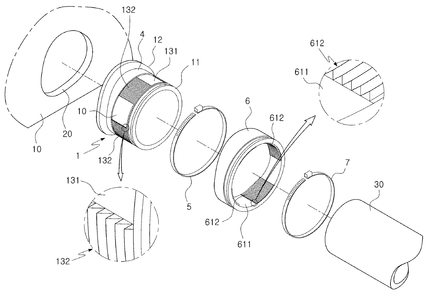
도 1은 본 발명의 하수관 연결구의 설치 상태를 나타낸 후방에서 본 분해사시도이고, 도 2는 본 발명에 따른 연결구 본체를 확대도시한 일부 절개사시도이며, 도 3은 본 발명의 하수관 연결구의 조립상태를 나타낸 종단면도이다.
1 is an exploded perspective view from the rear showing the installation state of the sewer pipe connector of the present invention, Figure 2 is a partial cutaway perspective view showing an enlarged connector body according to the present invention, Figure 3 is an assembled state of the sewer pipe connector of the present invention It is a longitudinal cross-sectional view shown.
도면에 도시된 바와 같이 본 발명의 하수관 연결구는, 삽입관(11)의 전방단부의 둘레에는 외측으로 돌출된 외측 걸림턱(12)이 형성되고 삽입관(11)의 외주면에는 삽입 걸림부(13)가 구비된 연결구본체와, 상기 삽입관(11)에 삽입되고 내주연에는 상기 삽입 걸림부(13)에 걸려 고정되는 걸림 고정부(61)가 구비되어 있는 고정링(6)과, 상기 삽입관(11)을 연결 하수관(30)에 고정하는 밴드 클램프(5)와, 상기 고정링(6)을 삽입관(11)에 고정하는 밴드 클램프(7)를 포함한다.
As shown in the figure, the sewer pipe connector of the present invention, the
그리고, 본 발명의 하수관 연결구는, 상기 삽입관(11)의 내주면의 전방 상,하부에 연결 하수관(30)의 삽입을 단속하는 내측 돌출턱(2)이 형성되고, 상기 상,하부의 내측 돌출턱(2)의 사이인 삽입관(11)의 내주면의 전방 양측에는 개방부(3)가 형성되며, 상기 연결구 본체(1)의 전방 단부 양측의 중간은 상기 연결 하수관(30)의 전방 단부면과 일치되게 상기 내측 돌출턱(2)의 후면과 일치되는 깊이로 함몰되게 형성된 것을 특징으로 한다.In addition, the sewer pipe connector of the present invention, the inner projection jaw (2) for intermittent insertion of the
상기 개방부(3)는, 상,하부에 형성된 상기 상,하 내측돌출턱의 단부턱(31)을 포함하여 단부턱(31)의 사이에 개방되게 형성되는 것이다. The
따라서 상기와 같이 삽입관(11)의 내주면 전방의 양측에 개방부(3)를 형성하고, 연결구 본체(1)의 전방 단부 양측의 중간과 연결 하수관(30)의 전방 단부면을 일치시킴으로써, 연결 하수관(30)으로 부터 유입되는 하수가 주 하수관(10)의 내부로 원활하게 유입되는 것이다. 즉 상기 삽입관(11)의 양측에 개방부(3)가 형성되고, 개방부(3)의 양측인 연결구 본체(1)의 전방 단부 양측의 중간이 하수 연결관의 단부와 일치되게 함몰되어 있음으로써, 연결 하수관(30)으로 유입되는 하수가 양측의 개방부(3)를 통과하여 함몰부분을 통해 주 하수관(10)으로 내부로 신속하고 원활하게 유입되는 것이다.
Therefore, as described above,
또한, 본 발명의 하수관 연결구는, 도 1 및 도 3에 도시된 바와 같이, 상기 상부에 형성된 내측 돌출턱(2)의 둘레 모서리부에는 전방으로 상향진 배수 경사면(21)이 함몰되게 형성되고, 상기 하부에 형성된 내측 돌출턱(2)의 둘레 모서리부에는 전방으로 하향진 배수 경사면(21)이 함몰되게 형성되어 있는 것이다.In addition, the sewer pipe connector of the present invention, as shown in Figures 1 and 3, the inclined corner portion of the inner protruding jaw (2) formed in the upper portion is formed to be recessed
따라서 상기와 같이 상,하부에 형성된 내측걸림턱의 모서리부에 함몰된 배수 경사면(21)을 더 형성함으로써, 연결 하수관(30)에서 유입되는 하수에 포함된 찌꺼기가 내측 걸림턱에 잔류됨이 없이 원활하게 배수될 수 있도록 하는 장점도 있는 것이다.
Therefore, by further forming a drain
또한, 본 발명의 하수관 연결구는, 도 2와 도 3에 도시된 바와 같이, 상기 연결구 본체(1)를 구성하는 상기 삽입관(11)의 외주면의 전방 둘레인 상기 외측 돌출턱의 후방에는, 주 하수관(10)에 형성된 관통홀(20)의 둘레 단부면과 밀착되는 수밀링(4)이 더 구비되어 있는 것이다.In addition, the sewage pipe connector of the present invention, as shown in Fig. 2 and 3, the rear of the outer projection jaw which is the front circumference of the outer peripheral surface of the
즉 상기 수밀링(4)은 판형의 링형상으로 구성되어 있는 것으로, 내측면이 상기 삽입관(11)의 둘레면에 접착제를 통해 접착 되거나, 또는 열융착으로 부착되어 있는 것이다. That is, the
따라서 상기 연결구 본체(1)를 구성하는 삽입관(11)의 외주면의 전방둘레에 주 하수관(10)에 형성된 관통홀(20)의 둘레면이 밀착되는 수밀링(4)을 더 형성함으로써, 주 하수관(10)의 관통홀(20)과 연결구 본체(1)의 밀봉력을 향상시킬 수 있는 것이다. 그러므로 본 발명에 따른 하수관 연결구를 장기간 동안 사용하더라도 주 하수관(10) 관통홀(20)의 둘레 단부면과 연결구 본체(1)의 사이에서 누수가 발생되는 것을 방지할 수 있는 것이다.
Therefore, by further forming a water-
한편, 도 2 및 도 3에 도시된 바와 같이, 본 발명을 구성하는 상기 삽입관(11)의 외주면에 형성된 삽입 걸림부(13)는, 링 삽입홈부(131)와 걸림랙부(132)가 등간격의 교호 형성되어 구성된다. On the other hand, as shown in Figures 2 and 3, the insertion locking portion 13 formed on the outer circumferential surface of the
상기 걸림랙부(132)는, 전방 수직다부(133a)와 전방 수직다부(133a)의 상부에서 후방으로 하향지게 형성된 후방 경사단부(133b)로 구성된 다수의 톱니(133)가 다수 열로 형성되어 구성된다. The
또한, 상기 고정링(6)의 내주연에 형성된 걸림 고정부(61)는, 상기 걸림랙부(132)가 전방에서 후방으로 저항 없이 삽입되는 관 삽입홈부(611)와 상기 링 삽입홈부(131)에 후방에서 전방으로 저항 없이 삽입되어 회전에 의해 상기 걸림랙부(132)에 걸리는 고정랙부(612)가 등간격의 교호로 형성되어 구성된다. In addition, the locking fixing portion 61 formed on the inner circumference of the
상기 고정랙부(612)는 후방 수직단부(613a)와 후방 수직단부(613a)의 상부에서 전방으로 하향지게 형성된 전방 경사단부(613b)로 구성된 다수의 톱니(613)가 다수 열로 형성되어 구성된다. The
따라서 상기와 같이, 삽입 걸림부(13)는 링 삽입홈부(131)와 걸림랙부(132)가 등간격의 교호 형성되고, 걸림 고정부(61)는 관 삽입홈부(611)와 고정랙부(612)가 등간격의 교호로 형성됨으로써, 상기 삽입 걸림부(13)를 구성하는 걸림랙부(132)와 상기 걸림 고정부(61)를 구성하는 고정랙부(612)를 서로 일치하지 않게 엇갈리게 한 상태에서 고정링(6)을 삽입링의 후방에 저항 없이 삽입한다. Therefore, as described above, the insertion locking portion 13 is the ring
다음 고정링(6)을 일정각도로 회전시켜 상기 걸림랙부(132)에 고정랙부(612)가 걸리게 하는 것이다. 즉 상기 고정랙부(612)를 구성하는 다수의 톱니(613)가 상기 걸림랙부(132)를 구성하는 다수의 톱니(133) 사이에 걸려 고정되게 하는 것이다. Next, the fixed
그러므로 상기 고정링(6)을 전방으로 저항 없이 밀어 이동시킨 다음, 일정 각도로 회전시키는 과정만을 통해 고정링(6)의 고정랙부(612)를 신속하면서 용이하게 삽입링의 걸림랙부(132)에 고정할 수 있는 장점도 있는 것이다.
Therefore, the fixed
이하, 상기와 같이 구성된 본 발명에 따른 하수관 연결구의 시공과정을 설명하면 다음과 같다. Hereinafter, the construction process of the sewer pipe connector according to the present invention configured as described above are as follows.
도 1 내지 도 3에 도시된 바와 같이, 본 발명의 하수관 연결구를 사용하여 주 하수관(10)의 관통홀(20)에 연결하수관을 시공할 경우에는, 먼저, 주 하수관(10)의 측부에 형성된 관통홀(20)에 연결구 본체(1)의 전방 둘레를 구부림에 따라 축소시켜 관통홀(20)에 삽입한 후 원상태로 복귀되게 한다. As shown in Figures 1 to 3, when constructing a sewer pipe to the through
그러면 상기 관통홀(20)의 내부 둘레면에 연결구 본체(1)를 구성하는 삽입관(11)의 전방 둘레에 형성된 수밀링(4)이 밀착되고, 상기 삽입관(11)의 전방단부의 둘레에 외측으로 돌출되게 형성된 외측 걸림턱(12)의 후면이 상기 관통홀(20)의 주위인 주 하수관(10)의 내측면에 밀착된다. Then, the water-
다음 상기 삽입관(11)의 외주면에 형성된 삽입 걸림부(13)를 구성하는 걸림랙부(132)와, 상기 고정링(6)의 내주면에 형성된 걸림 고정부(61)를 구성하는 고정랙부(612)를 서로 일치하지 않게 엇갈린 상태에서 고정링(6)을 삽입링의 후방에서 전방으로 밀어 슬라이딩 되게 삽입한다. 그런 후 고정링(6)을 일정각도로 회전시켜 상기 삽입관(11)의 걸림랙부(132)에 고정링(6)의 고정랙부(612)가 걸리게 하는 과정을 통해 고정링(6)을 삽입관(11)에 고정한다. Next, the
그리고 상기 삽입관(11)의 후방에 형성된 둘레홈부에 밴드 클램프(5)를 고정하여 삽입관(11)과 연결 하수관(30)을 상호 연결하고, 상기 고정링(6)의 후방에 형성된 둘레홈부에 밴드 클램프(7)를 고정하여 삽입관(11)과 고정링(6)의 연결함으로써, 주 하수관(10)의 관통홀(20)에 연결 하수관(30)의 연결을 완료하는 것이다.
Then, the
따라서, 상기와 같이 본 발명의 하수관 연결구를 시공함에 있어서, 삽입링에 고정링(6)을 전방으로 저항 없이 밀어 이동시킨 다음 일정 각도로 회전시키는 과정만을 통해 고정링(6)을 삽입관(11)에 신속하면서 용이하게 고정함으로써, 시공성이 우수한 하수관 연결구를 제공할 수 있는 것이다. Therefore, in the construction of the sewer pipe connector of the present invention as described above, the fixed ring (6) by moving the fixed ring (6) forward without resistance to the insertion ring and then rotates at a predetermined angle through the insertion ring (11) insertion pipe (11) By fast and easy fixing), it is possible to provide a sewer pipe connector having excellent workability.
이상에서 본 발명에 의한 하수관 연결구를 구체적으로 설명하였으나, 이는 본 발명의 가장 바람직한 실시양태를 기재한 것일 뿐, 본 발명이 이에 한정되는 것은 아니며, 첨부된 특허청구범위에 의해서 그 범위가 결정되어지고 한정되어진다. 또한, 이 기술분야에서 통상의 지식을 가진 자라면 누구나 본 발명의 명세서에 기재내용에 의하여 다양한 변형 및 모방을 행할 수 있는 것이나, 이 역시 본 발명의 범위를 벗어난 것이 아님은 명백하다고 할 것이다.
Although the sewage pipe connector according to the present invention has been described in detail above, this is only for describing the most preferred embodiment of the present invention, and the present invention is not limited thereto, and the scope thereof is determined by the appended claims. It is limited. In addition, any one of ordinary skill in the art can make various modifications and imitations according to the description in the specification of the present invention, but it will be apparent that this is also outside the scope of the present invention.
1 : 연결구 본체
11 : 삽입관
12 : 외측 걸림턱
13 : 삽입 걸림부
131 : 링 삽입홈부, 132 : 걸림랙부, 133 : 톱니,
133a : 전방 수직단부, 133b : 후방 경사단부
2 : 내측 돌출턱
21 : 배수 경사면
3 : 개방부
31 : 단부턱
4 : 수밀링
5 : 밴드 클램프
6 : 고정링
61 : 걸림 고정부
611 : 관 삽입홈부, 612 : 고정랙부, 613 : 톱니,
613a : 후방 수직단부, 613b : 전방 경사단부
7 : 밴드 클램프
10 : 주 하수관
20 : 관통홀
30 : 연결 하수관1 connector body
11: insertion tube
12: outer locking jaw
13: insertion stop
131: ring insertion groove, 132: locking rack, 133: tooth,
133a: front vertical end, 133b: rear inclined end
2: inner projection jaw
21: drainage slope
3: opening part
31: end jaw
4: water milling
5: band clamp
6: retaining ring
61: jamming part
611: tube insertion groove, 612: fixed rack, 613: tooth,
613a: rear vertical end, 613b: front inclined end
7: band clamp
10: main sewer pipe
20: Through hole
30: connection sewer
Claims (5)
상기 삽입관(11)의 내주면의 전방 상,하부에는 연결 하수관(30)의 삽입을 단속하는 내측 돌출턱(2)이 형성되고,
상기 상,하부의 내측 돌출턱(2)의 사이인 삽입관(11)의 내주면 전방의 양측에는 개방부(3)가 형성되며,
상기 연결구 본체(1)의 전방 단부의 양측의 중간은 상기 연결 하수관(30)의 전방 단부면과 일치되게 상기 내측 돌출턱(2)의 후면과 일치되는 깊이로 함몰되게 형성되고,
상기 상,하부의 내측 돌출턱(2)의 둘레 모서리부에는 전방으로 상향지고 전방으로 하향진 배수 경사면(21)이 각각 형성되어 있는 것을 특징으로 하는 하수관 연결구.
An outer locking jaw 12 is formed around the front end of the insertion tube 11, and a connector body 1 having an insertion locking portion 13 is provided on an outer circumferential surface of the insertion tube 11, and the insertion tube 11. And a band clamp for fixing the insertion pipe 11 to the sewer pipe 30 and the fixing ring 6 having a locking fixing portion 61 inserted into the inner circumferential surface and fixed to the insertion locking portion 13. (5) and a sewer pipe connector including a band clamp (7) for fixing the fixing ring (6) to the insertion pipe (11);
On the front upper and lower portions of the inner circumferential surface of the insertion pipe 11 is formed an inner projection jaw (2) to control the insertion of the connection sewage pipe 30,
Opening portions 3 are formed at both sides of the inner circumferential surface front of the insertion pipe 11 between the upper and lower inner protruding jaws 2,
The middle of both sides of the front end of the connector body 1 is formed to be recessed to a depth corresponding to the rear surface of the inner protruding jaw (2) to match the front end surface of the connection sewer (30),
The upper and lower inner protruding jaw (2) in the circumferential edge portion of the sewer pipe connector, characterized in that the drainage inclined surface 21 which is upwardly forward and downwardly forward.
상기 개방부(3)는,
상,하부에 형성된 상기 상,하 내측돌출턱의 단부턱(31)을 포함하여 단부턱(31)의 사이에 형성되는 것을 특징으로 하는 하수관 연결구.
The method of claim 1,
The opening part 3,
Sewage pipe connector characterized in that formed between the end jaw (31), including the end jaw (31) of the upper, lower inner projection jaw formed in the upper, lower portion.
상기 삽입관(11)의 외주면의 전방 둘레인 상기 외측 돌출턱의 후방에는,
주 하수관(10)의 관통홀(20)의 둘레 단부면과 밀착되는 수밀링(4)이 접착이나 열융착에 의해 더 구비되어 있는 것을 특징으로 하는 하수관 연결구.
The method of claim 1,
At the rear of the outer protruding jaw, which is the front circumference of the outer circumferential surface of the insertion pipe 11,
A sewer pipe connector characterized in that the water sealing ring (4) in close contact with the peripheral end surface of the through hole (20) of the main sewer pipe (10) is further provided by adhesion or heat fusion.
상기 삽입 걸림부(13)는, 링 삽입홈부(131)와 걸림랙부(132)가 등간격의 교호 형성되어 구성되고;
상기 걸림 고정부(61)는, 상기 걸림랙부(132)가 전방에서 후방으로 삽입되는 관 삽입홈부(611)와 상기 링 삽입홈부(131)에 후방에서 전방으로 삽입되어 회전에 의해 상기 걸림랙부(132)에 걸리는 고정랙부(612)가 등간격의 교호로 형성되어 구성되는 것을 특징으로 하는 하수관 연결구.
The method of claim 1,
The insertion locking portion 13 is formed by alternating ring insertion groove portion 131 and the locking rack portion 132 are formed at equal intervals;
The locking fixing portion 61 is inserted into the tube insertion groove 611 and the ring insertion groove 131 which is inserted from the front to the rear of the locking rack 132 from the rear to the locking rack ( 132, the fixed rack portion 612 is sewer pipe connector characterized in that formed by alternating at equal intervals.
상기 걸림랙부(132)는, 전방 수직다부(133a)와 전방 수직다부(133a)의 상부에서 후방으로 하향지게 형성된 후방 경사단부(133b)로 구성된 다수의 톱니(133)가 다수 열로 형성되어 구성되고;
상기 고정랙부(612)는, 후방 수직단부(613a)와 후방 수직단부(613a)의 상부에서 전방으로 하향지게 형성된 전방 경사단부(613b)로 구성된 다수의 톱니(613)가 다수 열로 형성되어 구성되는 것을 특징으로 하는 하수관 연결구. 5. The method of claim 4,
The locking rack 132 is composed of a plurality of teeth 133 composed of a plurality of teeth 133 composed of a front inclined portion 133a and a rear inclined end portion 133b formed downward from the upper portion of the front vertical portion 133a. ;
The fixed rack portion 612 is composed of a plurality of teeth 613 consisting of a plurality of teeth 613 composed of a front inclined end portion 613b formed downward from the top of the rear vertical end portion 613a and the rear vertical end portion 613a. Sewer pipe connector, characterized in that.
Priority Applications (1)
| Application Number | Priority Date | Filing Date | Title |
|---|---|---|---|
| KR1020110043914A KR101350205B1 (en) | 2011-05-11 | 2011-05-11 | A coupler for connecting drain pipe |
Applications Claiming Priority (1)
| Application Number | Priority Date | Filing Date | Title |
|---|---|---|---|
| KR1020110043914A KR101350205B1 (en) | 2011-05-11 | 2011-05-11 | A coupler for connecting drain pipe |
Publications (2)
| Publication Number | Publication Date |
|---|---|
| KR20120126257A true KR20120126257A (en) | 2012-11-21 |
| KR101350205B1 KR101350205B1 (en) | 2014-01-23 |
Family
ID=47511616
Family Applications (1)
| Application Number | Title | Priority Date | Filing Date |
|---|---|---|---|
| KR1020110043914A Active KR101350205B1 (en) | 2011-05-11 | 2011-05-11 | A coupler for connecting drain pipe |
Country Status (1)
| Country | Link |
|---|---|
| KR (1) | KR101350205B1 (en) |
Families Citing this family (3)
| Publication number | Priority date | Publication date | Assignee | Title |
|---|---|---|---|---|
| KR101903474B1 (en) * | 2016-11-08 | 2018-10-02 | 오강원 | Sealing pads for sewer pipe connections |
| KR20190045632A (en) | 2017-10-24 | 2019-05-03 | 오강원 | pipe connector |
| KR20220026107A (en) | 2020-08-25 | 2022-03-04 | 오준민 | Different diameter pipe connection socket for easy angle adjustment |
Family Cites Families (2)
| Publication number | Priority date | Publication date | Assignee | Title |
|---|---|---|---|---|
| KR200337231Y1 (en) * | 2003-10-06 | 2003-12-31 | 주식회사 삼정파인스 | a |
| KR200424708Y1 (en) * | 2006-05-01 | 2006-08-28 | 오강원 | Sewer pipe connection |
-
2011
- 2011-05-11 KR KR1020110043914A patent/KR101350205B1/en active Active
Also Published As
| Publication number | Publication date |
|---|---|
| KR101350205B1 (en) | 2014-01-23 |
Similar Documents
| Publication | Publication Date | Title |
|---|---|---|
| RU2515721C2 (en) | Flexible drain bellows | |
| AU2015281789B2 (en) | A debris trap | |
| KR101721631B1 (en) | Joint sturcture of precast concrete culvert unit using Magnetic packing material | |
| KR20120126257A (en) | A coupler for connecting drain pipe | |
| KR20120109897A (en) | Drain trap sleeve for bath | |
| JP4700213B2 (en) | Building drainage piping structure | |
| JP6159295B2 (en) | Manhole repair method | |
| KR20120007819U (en) | Alien substance emission function having drain watershoot | |
| KR20080105687A (en) | Sewer branch pipe connection structure | |
| KR100985990B1 (en) | Concrete Round Drain Pipe | |
| KR100995348B1 (en) | Manhole fixture | |
| KR101215873B1 (en) | Storm water attenuation and combined sewer overflows tank in best performance for anti-corrosion and leakage protection and its manufacturing method | |
| WO2018046348A1 (en) | An arrangement for a sewerage system comprising a french drain | |
| KR101641114B1 (en) | Manholes equipped with pipe connectors | |
| KR200314875Y1 (en) | Connector for apparatus draining | |
| KR20130051222A (en) | Pipe connector | |
| KR101175907B1 (en) | Supporting construct for hume pipe | |
| JP2006214225A (en) | Simple sluice for field | |
| CN202482943U (en) | Non-acute-angled V-shaped trap | |
| KR101168642B1 (en) | Connected assembly of pipe and sewage discharge apparatus | |
| KR20090003423U (en) | Connecting member for culvert bundle | |
| KR100851638B1 (en) | Prefabricated manhole for easy positioning and construction | |
| KR20080030812A (en) | Manhole rubber connector and construction method | |
| KR20080002978U (en) | Odor blocker for rain pipe | |
| KR200298291Y1 (en) | Manhole with drain |
Legal Events
| Date | Code | Title | Description |
|---|---|---|---|
| A201 | Request for examination | ||
| PA0109 | Patent application |
St.27 status event code: A-0-1-A10-A12-nap-PA0109 |
|
| PA0201 | Request for examination |
St.27 status event code: A-1-2-D10-D11-exm-PA0201 |
|
| PG1501 | Laying open of application |
St.27 status event code: A-1-1-Q10-Q12-nap-PG1501 |
|
| E902 | Notification of reason for refusal | ||
| PE0902 | Notice of grounds for rejection |
St.27 status event code: A-1-2-D10-D21-exm-PE0902 |
|
| E13-X000 | Pre-grant limitation requested |
St.27 status event code: A-2-3-E10-E13-lim-X000 |
|
| P11-X000 | Amendment of application requested |
St.27 status event code: A-2-2-P10-P11-nap-X000 |
|
| P13-X000 | Application amended |
St.27 status event code: A-2-2-P10-P13-nap-X000 |
|
| E90F | Notification of reason for final refusal | ||
| PE0902 | Notice of grounds for rejection |
St.27 status event code: A-1-2-D10-D21-exm-PE0902 |
|
| T11-X000 | Administrative time limit extension requested |
St.27 status event code: U-3-3-T10-T11-oth-X000 |
|
| P11-X000 | Amendment of application requested |
St.27 status event code: A-2-2-P10-P11-nap-X000 |
|
| P13-X000 | Application amended |
St.27 status event code: A-2-2-P10-P13-nap-X000 |
|
| E701 | Decision to grant or registration of patent right | ||
| PE0701 | Decision of registration |
St.27 status event code: A-1-2-D10-D22-exm-PE0701 |
|
| GRNT | Written decision to grant | ||
| PR0701 | Registration of establishment |
St.27 status event code: A-2-4-F10-F11-exm-PR0701 |
|
| PR1002 | Payment of registration fee |
St.27 status event code: A-2-2-U10-U11-oth-PR1002 Fee payment year number: 1 |
|
| PG1601 | Publication of registration |
St.27 status event code: A-4-4-Q10-Q13-nap-PG1601 |
|
| R18-X000 | Changes to party contact information recorded |
St.27 status event code: A-5-5-R10-R18-oth-X000 |
|
| P22-X000 | Classification modified |
St.27 status event code: A-4-4-P10-P22-nap-X000 |
|
| FPAY | Annual fee payment |
Payment date: 20161110 Year of fee payment: 4 |
|
| PR1001 | Payment of annual fee |
St.27 status event code: A-4-4-U10-U11-oth-PR1001 Fee payment year number: 4 |
|
| FPAY | Annual fee payment |
Payment date: 20171208 Year of fee payment: 5 |
|
| PR1001 | Payment of annual fee |
St.27 status event code: A-4-4-U10-U11-oth-PR1001 Fee payment year number: 5 |
|
| P22-X000 | Classification modified |
St.27 status event code: A-4-4-P10-P22-nap-X000 |
|
| R18-X000 | Changes to party contact information recorded |
St.27 status event code: A-5-5-R10-R18-oth-X000 |
|
| R18-X000 | Changes to party contact information recorded |
St.27 status event code: A-5-5-R10-R18-oth-X000 |
|
| FPAY | Annual fee payment |
Payment date: 20181231 Year of fee payment: 6 |
|
| PR1001 | Payment of annual fee |
St.27 status event code: A-4-4-U10-U11-oth-PR1001 Fee payment year number: 6 |
|
| FPAY | Annual fee payment |
Payment date: 20191217 Year of fee payment: 7 |
|
| PR1001 | Payment of annual fee |
St.27 status event code: A-4-4-U10-U11-oth-PR1001 Fee payment year number: 7 |
|
| PR1001 | Payment of annual fee |
St.27 status event code: A-4-4-U10-U11-oth-PR1001 Fee payment year number: 8 |
|
| PR1001 | Payment of annual fee |
St.27 status event code: A-4-4-U10-U11-oth-PR1001 Fee payment year number: 9 |
|
| PR1001 | Payment of annual fee |
St.27 status event code: A-4-4-U10-U11-oth-PR1001 Fee payment year number: 10 |
|
| PR1001 | Payment of annual fee |
St.27 status event code: A-4-4-U10-U11-oth-PR1001 Fee payment year number: 11 |
|
| PR1001 | Payment of annual fee |
St.27 status event code: A-4-4-U10-U11-oth-PR1001 Fee payment year number: 12 |
|
| PR1001 | Payment of annual fee |
St.27 status event code: A-4-4-U10-U11-oth-PR1001 Fee payment year number: 13 |
|
| U11 | Full renewal or maintenance fee paid |
Free format text: ST27 STATUS EVENT CODE: A-4-4-U10-U11-OTH-PR1001 (AS PROVIDED BY THE NATIONAL OFFICE) Year of fee payment: 13 |