KR20130002702A - 3 dimensional image display device and driving method thereof - Google Patents
3 dimensional image display device and driving method thereof Download PDFInfo
- Publication number
- KR20130002702A KR20130002702A KR1020110063824A KR20110063824A KR20130002702A KR 20130002702 A KR20130002702 A KR 20130002702A KR 1020110063824 A KR1020110063824 A KR 1020110063824A KR 20110063824 A KR20110063824 A KR 20110063824A KR 20130002702 A KR20130002702 A KR 20130002702A
- Authority
- KR
- South Korea
- Prior art keywords
- image
- eye image
- data
- gate
- left eye
- Prior art date
- Legal status (The legal status is an assumption and is not a legal conclusion. Google has not performed a legal analysis and makes no representation as to the accuracy of the status listed.)
- Granted
Links
Images





Classifications
-
- H—ELECTRICITY
- H04—ELECTRIC COMMUNICATION TECHNIQUE
- H04N—PICTORIAL COMMUNICATION, e.g. TELEVISION
- H04N13/00—Stereoscopic video systems; Multi-view video systems; Details thereof
-
- H—ELECTRICITY
- H04—ELECTRIC COMMUNICATION TECHNIQUE
- H04N—PICTORIAL COMMUNICATION, e.g. TELEVISION
- H04N13/00—Stereoscopic video systems; Multi-view video systems; Details thereof
- H04N13/30—Image reproducers
- H04N13/332—Displays for viewing with the aid of special glasses or head-mounted displays [HMD]
- H04N13/341—Displays for viewing with the aid of special glasses or head-mounted displays [HMD] using temporal multiplexing
-
- G—PHYSICS
- G02—OPTICS
- G02B—OPTICAL ELEMENTS, SYSTEMS OR APPARATUS
- G02B30/00—Optical systems or apparatus for producing three-dimensional [3D] effects, e.g. stereoscopic images
-
- G—PHYSICS
- G09—EDUCATION; CRYPTOGRAPHY; DISPLAY; ADVERTISING; SEALS
- G09G—ARRANGEMENTS OR CIRCUITS FOR CONTROL OF INDICATING DEVICES USING STATIC MEANS TO PRESENT VARIABLE INFORMATION
- G09G3/00—Control arrangements or circuits, of interest only in connection with visual indicators other than cathode-ray tubes
- G09G3/20—Control arrangements or circuits, of interest only in connection with visual indicators other than cathode-ray tubes for presentation of an assembly of a number of characters, e.g. a page, by composing the assembly by combination of individual elements arranged in a matrix no fixed position being assigned to or needed to be assigned to the individual characters or partial characters
- G09G3/34—Control arrangements or circuits, of interest only in connection with visual indicators other than cathode-ray tubes for presentation of an assembly of a number of characters, e.g. a page, by composing the assembly by combination of individual elements arranged in a matrix no fixed position being assigned to or needed to be assigned to the individual characters or partial characters by control of light from an independent source
- G09G3/3406—Control of illumination source
- G09G3/342—Control of illumination source using several illumination sources separately controlled corresponding to different display panel areas, e.g. along one dimension such as lines
-
- G—PHYSICS
- G09—EDUCATION; CRYPTOGRAPHY; DISPLAY; ADVERTISING; SEALS
- G09G—ARRANGEMENTS OR CIRCUITS FOR CONTROL OF INDICATING DEVICES USING STATIC MEANS TO PRESENT VARIABLE INFORMATION
- G09G3/00—Control arrangements or circuits, of interest only in connection with visual indicators other than cathode-ray tubes
- G09G3/20—Control arrangements or circuits, of interest only in connection with visual indicators other than cathode-ray tubes for presentation of an assembly of a number of characters, e.g. a page, by composing the assembly by combination of individual elements arranged in a matrix no fixed position being assigned to or needed to be assigned to the individual characters or partial characters
- G09G3/34—Control arrangements or circuits, of interest only in connection with visual indicators other than cathode-ray tubes for presentation of an assembly of a number of characters, e.g. a page, by composing the assembly by combination of individual elements arranged in a matrix no fixed position being assigned to or needed to be assigned to the individual characters or partial characters by control of light from an independent source
- G09G3/36—Control arrangements or circuits, of interest only in connection with visual indicators other than cathode-ray tubes for presentation of an assembly of a number of characters, e.g. a page, by composing the assembly by combination of individual elements arranged in a matrix no fixed position being assigned to or needed to be assigned to the individual characters or partial characters by control of light from an independent source using liquid crystals
- G09G3/3611—Control of matrices with row and column drivers
- G09G3/3648—Control of matrices with row and column drivers using an active matrix
-
- H—ELECTRICITY
- H04—ELECTRIC COMMUNICATION TECHNIQUE
- H04N—PICTORIAL COMMUNICATION, e.g. TELEVISION
- H04N13/00—Stereoscopic video systems; Multi-view video systems; Details thereof
- H04N13/30—Image reproducers
- H04N13/356—Image reproducers having separate monoscopic and stereoscopic modes
- H04N13/359—Switching between monoscopic and stereoscopic modes
-
- G—PHYSICS
- G09—EDUCATION; CRYPTOGRAPHY; DISPLAY; ADVERTISING; SEALS
- G09G—ARRANGEMENTS OR CIRCUITS FOR CONTROL OF INDICATING DEVICES USING STATIC MEANS TO PRESENT VARIABLE INFORMATION
- G09G2310/00—Command of the display device
- G09G2310/02—Addressing, scanning or driving the display screen or processing steps related thereto
- G09G2310/0202—Addressing of scan or signal lines
- G09G2310/0205—Simultaneous scanning of several lines in flat panels
-
- G—PHYSICS
- G09—EDUCATION; CRYPTOGRAPHY; DISPLAY; ADVERTISING; SEALS
- G09G—ARRANGEMENTS OR CIRCUITS FOR CONTROL OF INDICATING DEVICES USING STATIC MEANS TO PRESENT VARIABLE INFORMATION
- G09G2310/00—Command of the display device
- G09G2310/02—Addressing, scanning or driving the display screen or processing steps related thereto
- G09G2310/024—Scrolling of light from the illumination source over the display in combination with the scanning of the display screen
-
- G—PHYSICS
- G09—EDUCATION; CRYPTOGRAPHY; DISPLAY; ADVERTISING; SEALS
- G09G—ARRANGEMENTS OR CIRCUITS FOR CONTROL OF INDICATING DEVICES USING STATIC MEANS TO PRESENT VARIABLE INFORMATION
- G09G2310/00—Command of the display device
- G09G2310/06—Details of flat display driving waveforms
- G09G2310/061—Details of flat display driving waveforms for resetting or blanking
-
- G—PHYSICS
- G09—EDUCATION; CRYPTOGRAPHY; DISPLAY; ADVERTISING; SEALS
- G09G—ARRANGEMENTS OR CIRCUITS FOR CONTROL OF INDICATING DEVICES USING STATIC MEANS TO PRESENT VARIABLE INFORMATION
- G09G3/00—Control arrangements or circuits, of interest only in connection with visual indicators other than cathode-ray tubes
- G09G3/20—Control arrangements or circuits, of interest only in connection with visual indicators other than cathode-ray tubes for presentation of an assembly of a number of characters, e.g. a page, by composing the assembly by combination of individual elements arranged in a matrix no fixed position being assigned to or needed to be assigned to the individual characters or partial characters
- G09G3/34—Control arrangements or circuits, of interest only in connection with visual indicators other than cathode-ray tubes for presentation of an assembly of a number of characters, e.g. a page, by composing the assembly by combination of individual elements arranged in a matrix no fixed position being assigned to or needed to be assigned to the individual characters or partial characters by control of light from an independent source
- G09G3/36—Control arrangements or circuits, of interest only in connection with visual indicators other than cathode-ray tubes for presentation of an assembly of a number of characters, e.g. a page, by composing the assembly by combination of individual elements arranged in a matrix no fixed position being assigned to or needed to be assigned to the individual characters or partial characters by control of light from an independent source using liquid crystals
- G09G3/3611—Control of matrices with row and column drivers
- G09G3/3614—Control of polarity reversal in general
Landscapes
- Engineering & Computer Science (AREA)
- Physics & Mathematics (AREA)
- General Physics & Mathematics (AREA)
- Multimedia (AREA)
- Signal Processing (AREA)
- Theoretical Computer Science (AREA)
- Computer Hardware Design (AREA)
- Chemical & Material Sciences (AREA)
- Crystallography & Structural Chemistry (AREA)
- Optics & Photonics (AREA)
- Liquid Crystal (AREA)
- Control Of Indicators Other Than Cathode Ray Tubes (AREA)
- Liquid Crystal Display Device Control (AREA)
- Testing, Inspecting, Measuring Of Stereoscopic Televisions And Televisions (AREA)
Abstract
본 발명에 따른 입체 영상 표시 장치 및 그 구동 방법은 3D 모드인 경우에는 상기 2D 주파수보다 높은 3D 주파수로 좌안용 영상과 우안용 영상을 표시하며, 상기 좌안용 영상 또는 상기 우안용 영상을 연속하는 적어도 두 프레임에 걸쳐 동일 극성 및 동일 크기의 데이터 전압으로 데이터선에 인가하여 충전율 및 휘도를 향상시킨다. 또한, 상기 데이터선과 교차하는 복수의 게이트선에 총 데이터 지연값에 기초하여 계산된 보정 게이트 온 인가 시간만큼씩 순차적으로 게이트 온 전압을 인가하여 지연으로 인한 문제점을 제거한다.The stereoscopic image display device and the driving method thereof according to the present invention display a left eye image and a right eye image at a 3D frequency higher than the 2D frequency in the 3D mode, and at least one continuous image of the left eye image or the right eye image. The charging rate and brightness are improved by applying the data voltages of the same polarity and the same magnitude to the data lines over two frames. In addition, the gate-on voltage is sequentially applied to the plurality of gate lines crossing the data lines by the correction gate on application time calculated based on the total data delay value, thereby eliminating the problem caused by the delay.
Description
본 발명은 입체 영상 표시 장치 및 그 구동 방법에 대한 것이다.The present invention relates to a stereoscopic image display device and a driving method thereof.
오늘날 초고속 정보 통신망을 근간으로 구축된 정보의 고속화를 위해 실현될 서비스들은 현재의 전화와 같은 단순히 듣고 말하는 서비스로부터 문자, 음성, 영상을 고속 처리하는 디지털 단말을 중심으로 한 보고 듣는 멀티 미디어형 서비스로 발전하고 궁극적으로는 시공간을 초월하여 실감 있고 입체적으로 보고 느끼고 즐기는 초공간형 실감 3차원 입체 정보통신 서비스로 발전할 것으로 예상된다.The services to be realized for the high speed of information based on the high-speed information communication network today are the multimedia service centered on the digital terminal which processes text, voice, and video at high speed from the simple listening and speaking service such as the current telephone. It is expected to develop and ultimately develop into a super-spatial realistic 3D stereoscopic information communication service that can see, feel and enjoy realistic and three-dimensionally beyond time and space.
일반적으로 3차원을 표현하는 입체 영상은 두 눈을 통한 스테레오 시각의 원리에 의하여 이루어지게 되는데, 두 눈의 시차 즉, 두 눈이 약 65mm정도 떨어져서 존재하기 때문에 나타나게 되는 양안시차는 입체감의 가장 중요한 요인이라 할 수 있다. 즉, 좌우의 눈은 각각 서로 다른 2차원 화상을 보게 되고, 이 두 화상이 망막을 통해 뇌로 전달되면 뇌는 이를 정확히 서로 융합하여 본래 3차원 영상의 깊이감과 실제감을 재생하는 것이다. 이러한 능력을 통상 스테레오그라피(stereography)라 한다. In general, three-dimensional images representing three-dimensional image is made by the principle of stereo vision through two eyes. The parallax of two eyes, that is, binocular disparity that appears because two eyes are about 65mm apart, is the most important factor of three-dimensional effect. This can be called. In other words, each of the left and right eyes sees different two-dimensional images, and when these two images are transmitted to the brain through the retina, the brain accurately fuses each other to reproduce the depth and reality of the original three-dimensional image. This ability is commonly referred to as stereography.
입체 영상 표시 장치는 양안시차를 이용하는 것으로 관찰자의 별도의 안경착용 여부에 따라 안경식(stereoscopic)의 편광 방식과 시분할 방식, 비안경식(autostereoscopic)의 패럴랙스-배리어방식, 렌티큘러(lenticular)방식 및 블린킹 라이트(blinking light) 방식이 있다.The stereoscopic image display device uses binocular disparity, and according to whether the viewer wears separate glasses, stereoscopic polarization and time division, autostereoscopic parallax-barrier, lenticular and blinding There is a lighting (blinking light) method.
비안경식 입체 영상 표시 장치는 액정 표시 장치 위에 렌티 큘러 렌즈층과 같이 좌안용 영상과 우안용 영상을 분리하는 장치가 사용된다. 비안경식 입체 영상 표시 장치는 관찰자가 직접 스크린을 주시하게 되어 추가적인 안경 없이 입체 영상을 볼 수 있다는 장점이 있지만, 오른쪽 눈으로 전달되는 화상과 왼쪽 눈으로 전달되는 화상이 명확하게 구분되지 않아 입체감이 떨어지는 단점이 있다. In the non-stereoscopic 3D display device, a device for separating a left eye image and a right eye image, such as a lenticular lens layer, is used on a liquid crystal display. The non-glass type stereoscopic image display device has an advantage of allowing the observer to directly watch the screen so that the stereoscopic image can be viewed without additional glasses, but the image transmitted to the right eye and the image transmitted to the left eye are not clearly distinguished, resulting in poor stereoscopic effect. There are disadvantages.
한편, 안경식 입체 영상 표시 장치는 별도의 안경을 사용해야 한다는 점에서 추가 비용이 발생하지만, 많은 인원이 입체 영상을 즐길 수 있고 왼쪽 눈으로 전달되는 화상과 오른쪽 눈으로 전달되는 화상을 명확하게 구분시켜 입체감이 뛰어난 장점이 있다.On the other hand, the three-dimensional image display device is an additional cost in that separate glasses are used, but many people can enjoy the stereoscopic image, and clearly distinguish between the image transmitted to the left eye and the image delivered to the right eye This has an outstanding advantage.
본 발명이 이루고자 하는 기술적 과제는 별도의 패널 구조를 변경하지 않고도 고속 구동시 액정층에 충분한 전압 인가시간을 제공하여 표시하고자 하는 계조를 정확하게 표시할 수 있도록 하며, 입체 영상을 표시하더라도 일반 영상보다 휘도가 저하되는 것을 줄이는 입체 영상 표시 장치 및 그 구동 방법을 제공하고자 한다.The technical problem to be achieved by the present invention is to provide sufficient voltage application time to the liquid crystal layer during high-speed driving without changing a separate panel structure, so that it is possible to accurately display the gray scale to be displayed, even when displaying a three-dimensional image luminance than a normal image The present invention provides a stereoscopic image display device and a driving method thereof to reduce deterioration.
이러한 과제를 해결하기 위하여 본 발명의 실시예에 따른 입체 영상 표시 장치의 구동 방법은 2D 모드인지 3D 모드인지 판단하는 단계; 2D 모드인 경우에는 설정된 2D 주파수로 화상을 표시하는 단계; 3D 모드인 경우에는 상기 2D 주파수보다 높은 3D 주파수로 좌안용 영상과 우안용 영상을 표시하는 단계를 포함하며, 상기 좌안용 영상과 우안용 영상을 표시하는 단계는 상기 좌안용 영상 또는 상기 우안용 영상을 연속하는 적어도 두 프레임에 걸쳐 동일 극성 및 동일 크기의 데이터 전압으로 데이터선에 인가하는 단계; 및 상기 데이터선과 교차하는 복수의 게이트선에 총 데이터 지연값에 기초하여 계산된 보정 게이트 온 인가 시간만큼씩 순차적으로 게이트 온 전압을 인가하는 단계를 포함한다.In order to solve this problem, a method of driving a stereoscopic image display device according to an embodiment of the present invention comprises the steps of determining whether the 2D mode or 3D mode; Displaying an image at a set 2D frequency in the 2D mode; In the 3D mode, the method may include displaying a left eye image and a right eye image at a 3D frequency higher than the 2D frequency, and the displaying of the left eye image and the right eye image may include the left eye image and the right eye image. Applying the data lines with data voltages of the same polarity and the same magnitude over at least two consecutive frames; And sequentially applying gate on voltages to the plurality of gate lines crossing the data lines by the correction gate on application time calculated based on a total data delay value.
상기 보정 게이트 온 인가 시간은 상기 총 데이터 지연값을 상기 복수의 게이트선의 총 개수로 나눈 값인 기준 데이터 지연값을 1H의 시간에 더한 값일 수 있다.The correction gate on application time may be a value obtained by adding a reference data delay value, which is a value obtained by dividing the total data delay value by the total number of the plurality of gate lines, to a time of 1H.
상기 좌안용 영상 또는 상기 우안용 영상이 연속하여 인가되는 프레임 수를 x라고 하면, 상기 3D 모드에서 유효 충전 시간에서 총 게이트 지연값을 뺀 시간의 x배한 시간은 2D 모드에서의 유효 충전 시간에서 상기 총 게이트 지연값을 뺀 시간보다 크도록 마진을 제공할 수 있다.When x is the number of frames continuously applied to the left eye image or the right eye image, x times the effective charging time minus the total gate delay value in the 3D mode is equal to the effective charging time in the 2D mode. Margin can be provided to be greater than the time minus the total gate delay.
상기 3D 주파수는 상기 2D 주파수의 1.5배 내지 4배일 수 있다.The 3D frequency may be 1.5 to 4 times the 2D frequency.
상기 좌안용 영상 및 상기 우안용 영상을 포함하는 입체 영상 신호 그룹은 좌안용 영상 그룹과 우안용 영상 그룹으로 구분되며, 좌안용 영상 그룹의 마지막 프레임 및 우안용 영상 그룹의 마지막 프레임에는 블랙 영상이 포함되어 있을 수 있다.The stereoscopic image signal group including the left eye image and the right eye image are divided into a left eye image group and a right eye image group, and the last frame of the left eye image group and the last frame of the right eye image group include a black image. It may be.
상기 블랙 영상이 인가되는 프레임에서 게이트 온 전압은 상기 좌안용 영상 및 상기 우안용 영상이 인가되는 프레임에서 게이트 온 전압이 인가되는 시간의 두 배로 인가할 수 있다.In the frame to which the black image is applied, the gate on voltage may be applied twice as long as the gate on voltage is applied in the frame to which the left eye image and the right eye image are applied.
상기 입체 영상 표시 장치는 신호 처리부, 데이터 구동부, 게이트 구동부, 액정 표시 패널, 상기 액정 표시 패널의 배면에 위치하는 백라이트 및 안경을 포함하며, 상기 좌안용 영상과 우안용 영상을 표시하는 단계는 상기 신호 처리부로 입력되는 입력 영상 데이터를 3D 주파수에 적합하도록 재배열한 영상 데이터를 생성하고 상기 데이터 구동부로 출력하는 단계를 더 포함할 수 있다.The stereoscopic image display device includes a signal processor, a data driver, a gate driver, a liquid crystal display panel, a backlight and glasses positioned on a rear surface of the liquid crystal display panel, and the displaying of the left eye image and the right eye image may include displaying the signal. The method may further include generating rearranged image data of the input image data input to the processor to be suitable for the 3D frequency and outputting the rearranged image data to the data driver.
상기 좌안용 영상 및 상기 우안용 영상은 LLLRRR, LLBRRB, LLLLRRRR, LLLBRRRB 중 하나의 배열로 재배열 할 수 있으며, 여기서, L은 좌안용 영상, R은 우안용 영상, B는 블랙 영상을 나타낸다.The left eye image and the right eye image may be rearranged into one of LLLRRR, LLBRRB, LLLLRRRR, and LLLBRRRB, where L is a left eye image, R is a right eye image, and B is a black image.
상기 신호 처리부에서는 입력된 상기 입력 영상 데이터를 상기 재배열외에 DCC 처리를 수행한 후 상기 영상 데이터를 생성할 수 있다.The signal processor may generate the image data after performing DCC processing on the input image data.
상기 입체 영상 표시 장치는 액정 표시 패널 및 상기 액정 표시 패널의 배면에 위치하는 백라이트를 포함하며, 상기 좌안용 영상과 우안용 영상을 표시하는 단계는 상기 액정 표시 패널을 복수의 블록으로 구분하는 단계; 및 상기 백라이트에서 복수의 블록에 대응하는 부분을 각각 온/오프 시키거나 상기 백라이트 전체를 온/오프시키는 단계를 더 포함할 수 있다.The stereoscopic image display device includes a liquid crystal display panel and a backlight positioned on a rear surface of the liquid crystal display panel, and displaying the left eye image and the right eye image comprises: dividing the liquid crystal display panel into a plurality of blocks; And turning on / off portions corresponding to the plurality of blocks in the backlight, or turning on / off the entire backlight.
상기 입체 영상 표시 장치는 상기 입체 영상 표시 장치와 동기화되어 있는 안경을 더 포함하며, 상기 안경의 렌즈를 상기 입체 영상 표시 장치의 신호에 따라 온/오프시키는 단계를 더 포함할 수 있다.The stereoscopic image display apparatus may further include glasses synchronized with the stereoscopic image display apparatus, and the method may further include turning on / off a lens of the glasses according to a signal of the stereoscopic image display apparatus.
상기 입체 영상 표시 장치는 FRC부 및 신호 처리부, 데이터 구동부, 게이트 구동부, 액정 표시 패널, 상기 액정 표시 패널의 배면에 위치하는 백라이트 및 안경을 포함하며, 상기 좌안용 영상과 우안용 영상을 표시하는 단계는 상기 FRC부로 입력되는 외부 영상 신호를 수신하여 LLLRRR, LLBRRB, LLLLRRRR, LLLBRRRB과 같은 배열 중 하나로 재배열하여 상기 신호 처리부로 전달하는 단계를 더 포함할 수 있으며, 여기서, L은 좌안용 영상, R은 우안용 영상, B는 블랙 영상을 나타낸다.The stereoscopic image display device includes an FRC unit, a signal processor, a data driver, a gate driver, a liquid crystal display panel, a backlight and glasses positioned on a rear surface of the liquid crystal display panel, and displaying the left eye image and the right eye image. The method may further include receiving an external image signal input to the FRC unit, rearranging the external image signal to one of the arrangements such as LLLRRR, LLBRRB, LLLLRRRR, and LLLBRRRB, and transmitting the rear image signal to the signal processor, where L is a left eye image, R Is the right eye image, and B is the black image.
본 발명의 실시예에 따른 입체 영상 표시 장치는 2차원 영상을 표시하는 2D 모드와 입체 영상을 표시하는 3D 모드를 가지며, 신호 처리부, 데이터 구동부, 게이트 구동부 및 액정 표시 패널을 포함하는 입체 영상 표시 장치에서, 2D 모드를 표시할 때 동작하는 동작 주파수인 2D 주파수는 3D 모드를 표시할 때 동작하는 동작 주파수인 3D 주파수보다 작으며, 상기 신호 처리부는 좌안용 영상 또는 우안용 영상을 각각 연속하는 적어도 두 프레임에 걸쳐 동일 극성으로 상기 액정 표시 패널의 데이터선에 인가하도록 영상 데이터를 상기 데이터 구동부에 전달하며, 상기 신호 처리부는 상기 데이터선과 교차하는 복수의 게이트선에 상기 데이터선을 따라 데이터 전압이 지연되는 총 데이터 지연값에 기초하여 계산된 보정 게이트 온 인가 시간만큼씩 순차적으로 게이트 온 전압이 인가되도록 상기 게이트 구동부를 제어한다.A stereoscopic image display device according to an embodiment of the present invention has a 2D mode for displaying a 2D image and a 3D mode for displaying a 3D image, and includes a signal processor, a data driver, a gate driver, and a liquid crystal display panel. The 2D frequency, which is an operating frequency operating when displaying the 2D mode, is smaller than the 3D frequency, which is an operating frequency operating when displaying the 3D mode, and the signal processor is configured to include at least two consecutive left eye images or right eye images, respectively. Image data is transferred to the data driver to be applied to the data line of the liquid crystal display panel with the same polarity over a frame, and the signal processing unit delays the data voltage along the data line to a plurality of gate lines crossing the data line. Sequentially by the correction gate-on time calculated based on the total data delay value Sites on and controls the gate driver so that the applied voltage.
상기 보정 게이트 온 인가 시간은 상기 총 데이터 지연값을 상기 복수의 게이트선의 총 개수로 나눈 값인 기준 데이터 지연값을 1H의 시간에 더한 값일 수 있다.The correction gate on application time may be a value obtained by adding a reference data delay value, which is a value obtained by dividing the total data delay value by the total number of the plurality of gate lines, to a time of 1H.
상기 좌안용 영상 또는 상기 우안용 영상이 연속하여 인가되는 프레임 수를 x라고 하면, 상기 3D 모드에서 유효 충전 시간에서 총 게이트 지연값을 뺀 시간의 x배한 시간은 2D 모드에서의 유효 충전 시간에서 상기 총 게이트 지연값을 뺀 시간보다 클 수 있다.When x is the number of frames continuously applied to the left eye image or the right eye image, x times the effective charging time minus the total gate delay value in the 3D mode is equal to the effective charging time in the 2D mode. It can be greater than the time minus the total gate delay.
상기 3D 주파수는 상기 2D 주파수의 1.5배 내지 4배일 수 있다.The 3D frequency may be 1.5 to 4 times the 2D frequency.
상기 좌안용 영상 및 상기 우안용 영상을 포함하는 입체 영상 신호 그룹은 좌안용 영상 그룹과 우안용 영상 그룹으로 구분되며, 좌안용 영상 그룹의 마지막 프레임 및 우안용 영상 그룹의 마지막 프레임에는 블랙 영상이 포함되어 있을 수 있다.The stereoscopic image signal group including the left eye image and the right eye image are divided into a left eye image group and a right eye image group, and the last frame of the left eye image group and the last frame of the right eye image group include a black image. It may be.
상기 블랙 영상이 인가되는 프레임에서 게이트 온 전압은 상기 좌안용 영상 및 상기 우안용 영상이 인가되는 프레임에서 게이트 온 전압이 인가되는 시간의 두 배로 인가될 수 있다.In a frame to which the black image is applied, the gate on voltage may be applied twice as long as the time of applying the gate on voltage to the frame to which the left eye image and the right eye image are applied.
상기 신호 처리부는 프레임 메모리를 더 포함하며, 상기 신호 처리부는 입력된 입력 영상 데이터를 상기 프레임 메모리에 저장하고 3D 주파수에 적합하도록 재배열한 영상 데이터를 생성하여 상기 데이터 구동부로 출력할 수 있다.The signal processor may further include a frame memory, and the signal processor may store the input image data in the frame memory and generate rearranged image data to be suitable for a 3D frequency and output the image data to the data driver.
상기 좌안용 영상 및 상기 우안용 영상은 LLLRRR, LLBRRB, LLLLRRRR, LLLBRRRB와 같은 배열 중 하나로 재배열할 수 있으며, 여기서, L은 좌안용 영상, R은 우안용 영상, B는 블랙 영상을 나타낸다.The left eye image and the right eye image may be rearranged into one of the following arrangements, such as LLLRRR, LLBRRB, LLLLRRRR, LLLBRRRB, where L is a left eye image, R is a right eye image, and B is a black image.
상기 신호 처리부에서는 입력된 상기 입력 영상 데이터를 상기 재배열외에 DCC 처리가 수행될 수 있다.The signal processor may perform DCC processing in addition to the rearrangement of the input image data.
상기 입체 영상 표시 장치는 상기 액정 표시 패널의 배면에 위치하며 광원을 포함하는 백라이트를 포함하며, 상기 백라이트는 상기 광원을 일정 블록으로 구분한 후 블록별로 각각 온/오프하거나 상기 백라이트 전체를 온/오프할 수 있다.The stereoscopic image display device includes a backlight disposed on a rear surface of the liquid crystal display panel and including a light source, wherein the backlight divides the light source into a predetermined block, and then turns on / off each block or turns the entire backlight on / off. can do.
상기 입체 영상 표시 장치는 상기 입체 영상 표시 장치와 동기화되어 있는 안경을 더 포함하며, 상기 안경의 렌즈는 상기 입체 영상 표시 장치의 신호에 따라 온/오프될 수 있다.The stereoscopic image display apparatus may further include glasses synchronized with the stereoscopic image display apparatus, and the lens of the glasses may be turned on / off according to a signal of the stereoscopic image display apparatus.
상기 입체 영상 표시 장치는 FRC부를 더 포함하며, 상기 FRC부는 외부로부터 입력되는 외부 영상 신호를 수신하여 LLLRRR, LLBRRB, LLLLRRRR, LLLBRRRB와 같은 배열 중 하나로 재배열하여 상기 신호 처리부로 전달할 수 있으며, 여기서, L은 좌안용 영상, R은 우안용 영상, B는 블랙 영상을 나타낸다.The stereoscopic image display apparatus may further include an FRC unit, and the FRC unit may receive an external image signal input from the outside, rearrange it in one of the arrangements such as LLLRRR, LLBRRB, LLLLRRRR, LLLBRRRB, and transmit the same to the signal processor. L represents a left eye image, R represents a right eye image, and B represents a black image.
이상과 같이 좌안용 영상 또는 우안용 영상을 연속하는 적어도 두 프레임에 걸쳐 동일 극성으로 상기 액정 표시 패널의 데이터선에 인가하여 고 주파수에서도 충전량이 충분하도록 하며, 그에 따라 표시 휘도도 향상되도록 한다.As described above, the left eye image or the right eye image is applied to the data line of the liquid crystal display panel with the same polarity over at least two consecutive frames so that the charging amount is sufficient even at a high frequency, thereby improving display brightness.
또한, 게이트 전압 또는 데이터 전압의 지연을 보상하여 입체 영상 표시 장치를 구동하여 고 주파수에서도 표시 품질이 저하되지 않는다.In addition, the stereoscopic display device is driven by compensating for the delay of the gate voltage or the data voltage so that the display quality is not degraded even at a high frequency.
120Hz 또는 240Hz에서 2차원 영상을 표시하는데 문제가 없는 액정 표시 패널은 본 발명과 같이 좌안용 영상 및 우안용 영상을 적어도 두 프레임에 걸쳐 동일 극성으로 인가함으로 입체 영상에서도 표시 품질에 문제가 발생하지 않도록 할 수 있다. 그 결과 별도의 구성 요소를 추가하거내 액정 표시 패널의 구조를 변경할 필요가 없어 제작 비용이 획기적으로 감소된다.The liquid crystal display panel having no problem of displaying a two-dimensional image at 120 Hz or 240 Hz is applied to the left eye image and the right eye image with the same polarity over at least two frames, so that the display quality does not occur even in the stereoscopic image. can do. As a result, there is no need to add additional components or to change the structure of the liquid crystal display panel, thereby significantly reducing manufacturing costs.
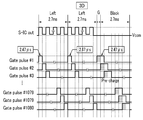
도 1은 본 발명의 실시예에 따른 입체 영상 표시 장치의 동작을 도시한 도면이다.
도 2는 본 발명의 실시예에 따른 입체 영상 표시 장치에서 입체 영상을 표시하기 위하여 게이트선 및 데이터선에 인가되는 신호의 파형도이다.
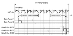
도 3은 본 발명의 실시예에 따른 입체 영상 표시 장치에서 2차원 영상을 표시하기 위하여 게이트선 및 데이터선에 인가되는 신호의 파형도이다.
도 4는 본 발명의 실시예에 따른 입체 영상 표시 장치에서 데이터 구동부로부터 멀어질수록 발생하는 데이터 전압의 지연을 보상하기 위하여 게이트 전압을 인가하는 방식을 도시한 파형도이다.
도 5는 본 발명의 실시예에 따른 입체 영상 표시 장치에서 게이트 구동부로부터 멀어질수록 발생하는 게이트 전압의 지연을 도시한 파형도이다.
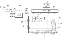
도 6은 본 발명의 실시예에 따른 입체 영상 표시 장치의 블록도이다.
도 7은 본 발명의 실시예에 따른 다양항 입체 영상 표시용 데이터의 예를 도시한 도면이다.
도 8은 본 발명의 실시예에 따른 입체 영상 표시 장치의 구동 방법을 나타낸 순서도이다.1 is a diagram illustrating an operation of a stereoscopic image display device according to an exemplary embodiment of the present invention.
2 is a waveform diagram of signals applied to gate lines and data lines in order to display stereoscopic images in the stereoscopic image display apparatus according to an exemplary embodiment of the present invention.
3 is a waveform diagram of signals applied to gate lines and data lines in order to display a 2D image in a 3D image display device according to an exemplary embodiment of the present invention.
FIG. 4 is a waveform diagram illustrating a method of applying a gate voltage in order to compensate for a delay of a data voltage generated when the stereoscopic image display device moves away from the data driver in accordance with an exemplary embodiment of the present invention.
FIG. 5 is a waveform diagram illustrating a delay of a gate voltage generated as the distance from a gate driver is increased in a stereoscopic image display device according to an exemplary embodiment of the present invention.
6 is a block diagram of a stereoscopic image display device according to an exemplary embodiment of the present invention.
7 is a diagram illustrating an example of various stereoscopic image display data according to an exemplary embodiment of the present invention.
8 is a flowchart illustrating a method of driving a stereoscopic image display device according to an exemplary embodiment of the present invention.
첨부한 도면을 참고로 하여 본 발명의 실시예에 대하여 본 발명이 속하는 기술 분야에서 통상의 지식을 가진 자가 용이하게 실시할 수 있도록 상세히 설명한다. 그러나 본 발명은 여러 가지 상이한 형태로 구현될 수 있으며 여기에서 설명하는 실시예에 한정되지 않는다.DETAILED DESCRIPTION Embodiments of the present invention will be described in detail with reference to the accompanying drawings so that those skilled in the art may easily implement the present invention. The present invention may, however, be embodied in many different forms and should not be construed as limited to the embodiments set forth herein.
도면에서 여러 층 및 영역을 명확하게 표현하기 위하여 두께를 확대하여 나타내었다. 명세서 전체를 통하여 유사한 부분에 대해서는 동일한 도면 부호를 붙였다. 층, 막, 영역, 판 등의 부분이 다른 부분 "위에" 있다고 할 때, 이는 다른 부분 "바로 위에" 있는 경우뿐 아니라 그 중간에 또 다른 부분이 있는 경우도 포함한다. 반대로 어떤 부분이 다른 부분 "바로 위에" 있다고 할 때에는 중간에 다른 부분이 없는 것을 뜻한다.In the drawings, the thickness is enlarged to clearly represent the layers and regions. Like parts are designated with like reference numerals throughout the specification. When a portion of a layer, film, region, plate, etc. is said to be "on top" of another part, this includes not only when the other part is "right on" but also another part in the middle. Conversely, when a part is "directly over" another part, it means that there is no other part in the middle.
이제 본 발명의 실시예에 따른 입체 영상 표시 장치에 대하여 도 1을 참고로 하여 상세하게 설명한다.Now, a stereoscopic image display device according to an embodiment of the present invention will be described in detail with reference to FIG. 1.
도 1은 본 발명의 실시예에 따른 입체 영상 표시 장치의 동작을 도시한 도면이다.1 is a diagram illustrating an operation of a stereoscopic image display device according to an exemplary embodiment of the present invention.
본 발명의 실시예에 따른 입체 영상 표시 장치는 기본적으로 입체 영상을 표시하는 모드(이하 3D 모드라 함)와 2차원 영상을 표시하는 모드(이하 2D 모드라 함)를 가진다.The stereoscopic image display apparatus according to the embodiment of the present invention basically has a mode for displaying a stereoscopic image (hereinafter referred to as 3D mode) and a mode for displaying a 2D image (hereinafter referred to as 2D mode).
본 실시예에 따른 입체 영상 표시 장치는 2D 모드로 영상을 표시할 때 사용되는 주파수(이하 2D 주파수라 함)와 3D 모드로 영상을 표시할 때 사용되는 주파수(이하 3D 주파수라 함)가 다르며, 2D 주파수가 3D 주파수보다 작다. 표시 장치에서 가장 기본적으로 사용되는 주파수(이하 기본 주파수라 함)가 60Hz라고 할 때, 3D 모드의 영상을 표시하기 위해서는 적어도 기본 주파수의 두 배의 주파수가 필요하다. 이는 좌안용 영상(L) 신호와 우안용 영상(R) 신호가 각각 표시되어야 하기 때문이다. 본 발명의 실시예에서는 2D 주파수로는 기본 주파수의 두 배인 120Hz 또는 네 배인 240Hz를 예로 들어 살펴보며, 3D 주파수로는 기본 주파수의 여섯 배인 360Hz 및 여덟 배인 480Hz를 예로 들어 살펴본다. 또한, 패널 별로 기본 주파수는 다양할 수 있어 60Hz 이외의 주파수를 사용할 수도 있다.In the stereoscopic image display apparatus according to the present embodiment, a frequency (hereinafter, referred to as 2D frequency) used when displaying an image in 2D mode and a frequency (hereinafter, referred to as 3D frequency) used when displaying an image in 3D mode are different from each other. 2D frequency is less than 3D frequency. When the frequency most commonly used in the display device (hereinafter, referred to as a fundamental frequency) is 60 Hz, at least twice the frequency of the fundamental frequency is required to display an image in 3D mode. This is because the left eye image L signal and the right eye image R signal should be displayed respectively. In the embodiment of the present invention, the 2D frequency is taken as an example of 120Hz or four times 240Hz, which is twice the fundamental frequency, and the 3D frequency is taken as an example of 360Hz and 480Hz, which is six times the fundamental frequency, as an example. In addition, since the fundamental frequency may vary from panel to panel, frequencies other than 60 Hz may be used.
3D 모드를 표시하기 위해서는 좌안용 영상은 왼쪽 눈으로 인가되고, 우안용 영상은 오른쪽 눈으로 인가되어야 한다. 이를 위하여 본 발명의 실시예에 따른 입체 영상 표시 장치(300)는 좌안용 영상을 표시하는 구간과 우안용 영상을 표시하는 구간을 구분하여 표시한다. 또한, 안경(100)을 사용하여 좌안용 영상이 표시된 구간에서는 왼쪽 렌즈가 투명하게 되고 오른쪽 렌즈가 불투명하게 되어 왼쪽 눈으로만 입체 영상 표시 장치(300)를 볼 수 있도록 하며, 우안용 영상이 표시된 구간에서는 반대로 오른쪽 눈으로만 입체 영상 표시 장치(300)를 볼 수 있도록 한다. 그 결과 좌안용 영상은 왼쪽 눈으로 인가되고, 우안용 영상은 오른쪽 눈으로 인가되어 입체 영상을 볼 수 있다.In order to display the 3D mode, the left eye image is applied to the left eye and the right eye image is applied to the right eye. To this end, the stereoscopic
이와 같이 안경(100)을 온/오프 시켜 입체 영상 표시 장치(300)를 보는 경우에는 좌안용 영상과 우안용 영상이 겹치는 크로스 토크 문제를 제거하기 위하여 좌안용 영상과 우안용 영상 사이에 블랙 데이터를 삽입하거나 백라이트의 전부 또는 일부를 일정 시간동안 오프시키거나 안경(100)의 양쪽 렌즈를 모두 불투명하게 할 수 있다. 이러한 방식 중 도 1의 실시예에서는 블랙 데이터를 삽입하고 백라이트를 복수의 블록으로 구분하여 블록별로 온/오프 시키는 방식을 사용한다.When viewing the stereoscopic
도 1에 도시되어 있는 파형도는 360Hz로 입체 영상을 표시하는 경우로 좌안용 영상으로는 화이트를 표시하며, 우안용 영상으로는 블랙을 표시하는 경우를 나타낸다.The waveform diagram shown in FIG. 1 shows a case where a stereoscopic image is displayed at 360 Hz, white is displayed as a left eye image, and black is displayed as a right eye image.
이하 도 1에 대하여 상세하게 설명하면 아래와 같다.Hereinafter, FIG. 1 will be described in detail.
도 1에 따른 입체 영상 표시 장치(300)의 액정 표시 패널은 게이트선을 따라서 가로 방향으로 연장되어 있는 8개의 블록(block)으로 구분되어 있다. 도 1에서는 각 블록을 나타내기 위하여 입체 영상 표시 장치(300)내에 점선을 추가하여 구분하였다. 각 블록은 동일한 개수의 게이트선을 포함한다. The liquid crystal display panel of the stereoscopic
입체 영상 표시 장치(300)는 액정 표시 패널의 배면에 위치하는 백라이트를 포함한다. 백라이트는 CCFL과 같은 형광 램프를 포함할 수도 있고, LED와 같은 발광 다이오드를 포함할 수도 있는데, 도 1의 실시예에서는 LED를 기준으로 살펴본다.The stereoscopic
백라이트에 형성되어 있는 LED는 액정 표시 패널의 특정 블록에만 빛을 제공하거나 제공하지 않을 수 있도록 배치되어 있으며, 해당 블록에 대응하는 LED를 온/오프시켜 해당 블록에 포함되는 화소에서 표시하는 화상이 외부에서는 시인할 수 없도록 한다.The LEDs formed in the backlight are arranged to provide or not provide light only to a specific block of the liquid crystal display panel, and the image displayed by the pixels included in the block is turned on by turning on / off the LED corresponding to the block. Do not allow it to be recognized.
도 1에서는 해당 블록에 대응하는 LED가 온/오프 되는 타이밍을 파형도 상에 도시하였다. 파형도 상에서 "LED On"에 대응하는 화이트 색으로 표시된 부분은 백라이트의 LED가 켜진 구간을 의미하며, "LED Off"에 대응하는 회색으로 표시된 부분은 백라이트의 LED가 꺼진 구간을 나타낸다. 즉, 첫번째 블록(Block #1)은 대응하는 LED가 꺼진 상태가 4.05ms동안 유지되다가 켜진 상태로 변경되며, 4.05ms를 주기로 반복된다. 여기서 4.05ms는 360Hz 구동시 1H 기간인 2.7ms의 1.5배의 값이며, LED의 온과 오프간의 듀티비는 50%이다. 두번째 블록(Block #2)에 대응하는 LED는 첫번째 블록(Block #1)보다 약 0.3ms정도 뒤에 동작한다. 즉, 첫번째 블록(Block #1)에 대응하는 LED가 켜지면, 약 0.3ms정도 뒤에 두번째 블록(Block #2)에 대응하는 LED도 켜지고, 첫번째 블록(Block #1)에 대응하는 LED가 꺼지면, 약 0.3ms정도 뒤에 두번째 블록(Block #2)에 대응하는 LED도 꺼진다. 도 1에서 도시하고 있는 바와 같이 각 블록은 약 0.3ms를 간격으로 순차적으로 동작한다.In FIG. 1, the timing at which an LED corresponding to the block is turned on / off is illustrated on a waveform diagram. In the waveform diagram, a portion indicated by white color corresponding to “LED On” indicates a section in which the LED of the backlight is turned on, and a portion indicated in gray corresponding to “LED Off” indicates a section in which the LED of the backlight is turned off. That is, the first block (Block # 1) is changed to the state in which the corresponding LED is turned off after being maintained for 4.05 ms, and is repeated every 4.05 ms. Here, 4.05ms is 1.5 times the value of 2.7ms, which is the 1H period when driving at 360Hz, and the duty ratio between the LED on and off is 50%. The LED corresponding to the second block (Block # 2) operates about 0.3 ms after the first block (Block # 1). That is, when the LED corresponding to the first block (Block # 1) turns on, after about 0.3 ms, the LED corresponding to the second block (Block # 2) also turns on, and when the LED corresponding to the first block (Block # 1) turns off, After about 0.3ms, the LED corresponding to the second block (Block # 2) also turns off. As shown in FIG. 1, each block operates sequentially at intervals of about 0.3 ms.
도 1의 우측 파형도에서 각 블록마다 도시된 파형은 입체 영상을 표시하는 경우의 대표적인 액정층의 응답을 나타내며, 최대 응답에서는 화이트를 표시하고 최소 응답에서는 블랙을 표시한다. In the waveform diagram on the right side of FIG. 1, the waveform shown for each block represents the response of the representative liquid crystal layer in the case of displaying a stereoscopic image, and displays white at the maximum response and black at the minimum response.
입체 영상을 표시하기 위하여 도 1의 실시예에서는 360Hz의 주파수로 좌안용 영상 데이터(L), 좌안용 영상 데이터(L), 블랙 영상 데이터(B), 우안용 영상 데이터(R), 우안용 영상 데이터(R), 블랙 영상 데이터(B)을 순차적으로 그리고 반복적으로 표시한다. 이하에서는 이를 간단하게 'LLBRRB'로도 나타내며, 이들은 입체 영상 신호 그룹이라고 한다. In order to display a stereoscopic image, in the embodiment of FIG. 1, the left eye image data L, the left eye image data L, the black image data B, the right eye image data R, and the right eye image are displayed at a frequency of 360 Hz. The data R and the black image data B are sequentially and repeatedly displayed. Hereinafter, this is also simply referred to as 'LLBRRB', which is called a stereoscopic image signal group.
도1의 파형도에서는 좌안용 영상 데이터(L)로는 화이트가 인가되며, 각 블록에서 좌안용 영상 데이터(L)가 첫번째로 인가되는 프레임 동안에는 액정층이 데이터 전압을 충분한 시간동안 인가받지 못하여 원하는 휘도인 화이트를 표시하지 못한다.In the waveform diagram of FIG. 1, white is applied to the left eye image data L, and the liquid crystal layer does not receive the data voltage for a sufficient time during the first frame to which the left eye image data L is applied in each block. It does not display white.
이는 360Hz로 구동하는 경우 한 프레임이 2.7ms이지만, 풀 HD의 해상도를 가지는 패널의 경우에는 1080개의 게이트선이 있어 하나의 게이트선에 게이트 온 전압을 인가할 수 있는 시간(이하 유효 충전 시간이라 함)은 약 2.47μs이다. (도 2 참고) 약 2.47μs이라는 시간은 240Hz로 화상을 표시할 때 사용되는 유효 충전 시간인 3.7μs(도 3 참고)에 못 미쳐 충분한 충전이 이루어지지 않는다.In case of driving at 360Hz, one frame is 2.7ms, but in case of panel having full HD resolution, there are 1080 gate lines so that the gate-on voltage can be applied to one gate line (hereinafter referred to as effective charging time). ) Is about 2.47 μs. (See Fig. 2) The time of about 2.47 μs is not enough charge to reach 3.7 μs (see Fig. 3), which is an effective charging time used when displaying an image at 240 Hz.
이와 같이 액정층이 충분한 시간동안 충전되지 못하는 문제가 발생할 수 있으므로 본 발명의 실시예에서는 동일한 극성으로 좌안용 데이터 전압을 적어도 한번 더 인가한다. 그 결과 두번째 프레임에서는 목표 휘도인 화이트를 표시할 수 있게 된다. 이는 첫번째 유효 충전 시간과 두번째 유효 충전 시간을 더한 유효 충전 시간동안 액정층이 충전되는 것과 실질적으로 동일하므로 총 4.94μs (2.47*2) 동안 충전되는 효과를 가진다. As such, a problem in that the liquid crystal layer may not be charged for a sufficient time may occur. In the exemplary embodiment of the present invention, the left eye data voltage is applied at least once with the same polarity. As a result, white, which is the target luminance, can be displayed in the second frame. This is substantially the same as that of the liquid crystal layer being charged during the effective charging time plus the first effective charging time and the second effective charging time, and thus has the effect of being charged for a total of 4.94 μs (2.47 * 2).
즉, 본 발명의 실시예에서는 3D 모드로 입체 영상을 표시함에 있어서 2D 모드보다 고 주파수로 화상을 표시하도록 하여 유효 충전 시간이 줄어들 수 있는 문제가 발생할 수 있지만, 적어도 두 번 연속하여 동일한 극성의 좌안용 데이터 전압 또는 우안용 데이터 전압을 인가하여 충분한 충전 시간을 확보한다. 적어도 두번 연속하여 인가된 좌안용 영상 데이터 또는 우안용 영상 데이터 중 첫번째 프레임에 인가된 것은 프리 차지의 효과를 가져, 프리 차지용 영상 데이터라고도 한다.That is, in the exemplary embodiment of the present invention, when displaying a stereoscopic image in 3D mode, a problem may occur in that the effective charging time may be reduced by displaying an image at a higher frequency than in the 2D mode, but at least two consecutive eyes of the same polarity may occur. A sufficient charging time is secured by applying a data voltage or a right eye data voltage. What is applied to the first frame of the left eye image data or the right eye image data applied at least two times in succession is also referred to as precharge image data.
도 1의 파형도에 의하면 그 다음 프레임(세번째 프레임)에는 블랙 데이터가 삽입되어 블랙 영상을 표시하게 된다. According to the waveform diagram of FIG. 1, black data is inserted into the next frame (third frame) to display a black image.
네번째 프레임에서는 우안용 영상 데이터(R)가 입력되며, 우안용 영상 데이터(R)도 충분한 유효 충전 시간을 확보하지 못하므로 추가적으로 다섯번째 프레임에서도 동일한 극성의 우안용 데이터 전압을 다시 한번 더 입력하여 충분한 유효 충전 시간을 확보할 수 있도록 한다. 그 후, 여섯번째 프레임에서는 블랙 데이터가 삽입되어 블랙 영상을 표시하게 된다. 다만 도 1에서는 우안용 영상 데이터(R)로 블랙 데이터를 사용하고 있어 우안용 영상 데이터(R)과 블랙 영상 데이터(B)가 동일하여 혼란의 우려가 있지만, 도 1에서는 입체 영상 표시 장치(300)의 동작을 설명하기 위하여 우안용 영상 데이터(R)를 블랙으로 한정한 것이고, 실제로는 다양한 계조의 데이터가 표시되어 차이가 있다.In the fourth frame, the right eye image data R is inputted, and the right eye image data R also does not have sufficient effective charging time. Therefore, in the fifth frame, the right eye image data voltage having the same polarity is input again. Ensure an effective charge time. Thereafter, in the sixth frame, black data is inserted to display a black image. In FIG. 1, black data is used as the right eye image data R, and the right eye image data R and the black image data B are the same, which may cause confusion. The right eye image data R is limited to black in order to explain the operation of). Actually, various gray levels of data are displayed and there is a difference.
이상과 같이 하나의 입체 영상 신호 그룹(LLBRRB)이 표시 패널에 표시되면, 총 6개의 프레임이 필요하며, 360Hz로 6개 프레임이 소비되며, 이는 60Hz의 기본 주파수로는 한 프레임과 동일한 시간이다.When one stereoscopic image signal group LLBRRB is displayed on the display panel as described above, a total of six frames are required, and six frames are consumed at 360 Hz, which is the same time as one frame at a fundamental frequency of 60 Hz.
하나의 입체 영상 신호 그룹이 표시됨과 함께 백라이트의 LED는 온/오프 동작하며, 안경(100)도 좌측 렌즈와 우측 렌즈가 온/오프 동작하게 된다.As one stereoscopic image signal group is displayed, the LED of the backlight is turned on and off, and the
도 1을 참고하면, 각 블록에 대응하는 LED는 약 0.3ms의 간격으로 순차적으로 온/오프 동작하며, 온과 오프간의 듀티비는 50%이다. 온/오프 간의 듀티비는 실시예에 따라서는 보다 온 구간을 늘릴 수 있으며, 60~70%로 온 구간을 늘릴 수도 있다. LED가 온될 때 액정층은 원하는 계조를 표시할 수 있도록 배열되어 있어야 LED의 온 구간을 늘리기 위해서는 액정의 충전시간에 따른 응답속도가 빠를 필요가 있다.Referring to FIG. 1, LEDs corresponding to each block are sequentially turned on and off at intervals of about 0.3 ms, and the duty ratio between on and off is 50%. According to the embodiment, the duty ratio between on / off may be increased on interval, and the on interval may be increased to 60 to 70%. When the LED is turned on, the liquid crystal layer should be arranged so as to display a desired gray scale, so that the response speed according to the charging time of the liquid crystal needs to be fast to increase the on period of the LED.
이 때 안경(100)에서 좌측 렌즈를 투명하도록 온되는 때는 우안용 영상이 표시 패널에서 모두 제거된 후(또는, 모든 패널에 삽입되는 블랙 데이터가 모두 표시된 후)이며, 그 이후에 표시되는 좌안용 영상을 모두 시인할 수 있도록 온 상태를 유지한다. 다만, 좌측 렌즈가 온된 상태에서도 각 블록에서는 LED가 오프된 상태와 온된 상태를 반복 동작하고 있으므로 검은 화면을 적어도 일부 시인하게 된다. 그 후, 좌안용 영상이 표시 패널에서 모두 제거되면, (또는, 모든 패널에 삽입되는 블랙 데이터가 모두 표시되면) 좌측 렌즈가 오프되어 불투명하게 되고, 우측 렌즈가 온되어 투명하게 된다.In this case, when the left lens of the
이상에서는 도 1을 통하여 전체적으로 입체 영상을 표시하는 방식을 살펴보았으며, 이하에서는 도 2를 통하여 입체 영상을 표시함에 있어서 인가되는 게이트 신호 및 데이터 신호를 중심으로 살펴본다.In the above, a method of displaying a stereoscopic image as a whole is described with reference to FIG. 1, and the following description will be made with reference to a gate signal and a data signal applied in displaying a stereoscopic image through FIG. 2.
도 2는 본 발명의 실시예에 따른 입체 영상 표시 장치에서 입체 영상을 표시하기 위하여 게이트선 및 데이터선에 인가되는 신호의 파형도이다.2 is a waveform diagram of signals applied to gate lines and data lines in order to display stereoscopic images in the stereoscopic image display apparatus according to an exemplary embodiment of the present invention.
도 2에서는 각 블록에 대응하는 LED의 온/오프와 안경(100)의 렌즈가 온/오프되는 타이밍은 제외하고 액정 표시 패널의 하나의 데이터선 및 이와 교차하는 1080개의 게이트선에 인가되는 신호를 도시하고 있다. 또한, 도 2에서는 하나의 입체 영상 신호 그룹(LLBRRB) 중 좌안용 영상 그룹(LLB)만을 도시하고 있으며, 우안용 영상 그룹(RRB)은 도 2와 유사하므로 생략하고 있다.In FIG. 2, signals applied to one data line of the liquid crystal display panel and 1080 gate lines crossing the same are excluded except for timings of turning on / off the LEDs corresponding to the blocks and turning on / off the lenses of the
먼저 첫번째 프레임의 첫번째 1H(1 수평 주기)에서는 첫번째 게이트선에 첫번째 게이트 온 전압(Gate pulse #1)이 인가되며, 두번째 1H 동안에는 두번째 게이트선에 두번째 게이트 온 전압(Gate pulse #2)가 인가되며, 1H 간격으로 1080번째 게이트선까지 게이트 온 전압이 순차적으로 인가된다. 이와 함께 데이터 구동부의 출력단(S-IC out)에서는 1H 간격으로 좌안용 영상 신호에 대응하는 데이터 전압(이하 좌안용 데이터 전압이라 함)을 인가한다. 실제 데이터 구동부의 출력단(S-IC out)에서는 좌안용 데이터 전압은 인가될 각 화소에 따라서 서로 다른 크기의 전압값이 인가되겠지만, 도 2에서는 단순하게 출력되는 전압이 변하고 있다는 점만을 명확하게 도시하였다. 한편, 도 2에서는 데이터 구동부의 출력단(S-IC out)에서 출력되는 좌안용 데이터 전압이 공통 전압(Vcom)보다 높아 동일한 극성을 가지는 데이터 전압이 인가되는 것으로 도시되어 있지만, 실시예에 따라서는 한 프레임내에서 일정한 규칙에 따라서 극성이 다른 데이터 전압을 인가할 수도 있다.First, the first gate on voltage (Gate pulse # 1) is applied to the first gate line in the first 1H (1 horizontal period) of the first frame, and the second gate on voltage (Gate pulse # 2) is applied to the second gate line during the second 1H. The gate-on voltage is sequentially applied to the 1080th gate line at 1H intervals. At the same time, the output terminal S-IC out of the data driver applies a data voltage (hereinafter, referred to as a left eye data voltage) corresponding to the left eye image signal at intervals of 1H. In the output terminal (S-IC out) of the actual data driver, different values of voltage values may be applied according to each pixel to be applied, but in FIG. 2, only the output voltage is clearly changed. . Meanwhile, although FIG. 2 illustrates that the left eye data voltage output from the output terminal S-IC out of the data driver is higher than the common voltage Vcom, a data voltage having the same polarity is applied. In the frame, data voltages having different polarities may be applied according to a predetermined rule.
그 후, 두번째 프레임에서도 첫번째 프레임과 같이 1H 간격으로 순차적으로 게이트 온 전압이 인가되며, 데이터 구동부의 출력단(S-IC out)도 1H 간격으로 좌안용 데이터 전압을 데이터선으로 인가한다. 여기서 동일한 화소에 인가되는 첫번째 프레임 및 두번째 프레임에서의 좌안용 영상 신호에 따른 데이터 전압은 극성 및 크기가 동일하다. 이는 한 프레임만으로 유효 충전 시간이 충분하지 않기 때문에 두 프레임에 걸쳐 충전이 이루어지도록 하기 위함이다. 그 결과 첫번째 프레임에서 인가된 데이터 전압은 프리 차지의 특성을 가져 프리 차지용 데이터 전압이라고도 한다. Thereafter, the gate-on voltage is sequentially applied to the second frame at 1H intervals as in the first frame, and the output terminal S-IC out of the data driver also applies the left eye data voltage to the data line at intervals of 1H. Here, the data voltages according to the left eye image signal in the first frame and the second frame applied to the same pixel have the same polarity and magnitude. This is for charging over two frames because the effective charging time is not enough in one frame. As a result, the data voltage applied in the first frame has a characteristic of precharge and is also called a precharge data voltage.
세번째 프레임에서는 블랙 데이터가 인가되며, 한 프레임 동안에만 블랙 데이터가 인가되어야 하므로 블랙 데이터의 유효 충전 시간이 불충분한 문제가 발생할 수 있다. 이에 도 2의 실시예에서는 하나의 게이트선에 인가되는 게이트 온 시간을 1H의 두 배인 2H로 수정하여 인가하고 있다.In the third frame, black data is applied, and since black data should be applied only during one frame, insufficient charging time of black data may occur. Accordingly, in the embodiment of FIG. 2, the gate-on time applied to one gate line is modified to 2H, which is twice as high as 1H.
이를 위하여 도 2의 실시예에서는 두번째 프레임과 세번째 프레임의 사이의 블랭크 기간(G) 중에 첫번째 게이트선에 첫번째 게이트 온 펄스(Gate pulse #1)를 미리 인가하고, 2H 동안 유지시킨다. 첫번째 게이트 온 펄스(Gate pulse #1)의 인가로부터 1H 이후에는 두번째 게이트선에 두번째 게이트 온 펄스(Gate pulse #2)를 인가하고 2H(약 4.94μs)동안 유지시킨다. 이와 같이 1H를 주기로 각 게이트선에 순차적으로 2H 동안 지속되는 게이트 온 펄스를 인가한다. 이와 같이 게이트 온 전압이 인가되는 중에 데이터 구동부의 출력단(S-IC out)에서는 블랙 데이터 전압(일 예로 공통 전압(Vcom))이 일정하게 인가된다. 그 결과 한 프레임인 2.7ms 동안에만 블랙 영상(B)이 인가되지만, 각 화소에서는 충분한 유효 충정 시간동안 충전되고 블랙 영상이 표시된다. To this end, in the embodiment of FIG. 2, the first gate-on pulse #
실시예에 따라서는 블랙 영상을 표시하기 위하여 모든 게이터선에 게이트 온 전압을 동시에 인가할 수도 있다. 이때에도 유효 충전 시간을 고려하면 게이트 온 전압이 유지되는 시간은 2H 이상인 것이 바람직하다.In some embodiments, the gate-on voltage may be simultaneously applied to all the gate lines in order to display the black image. In this case, considering the effective charging time, the time for which the gate-on voltage is maintained is preferably 2H or more.
이상에서는 도 1 및 도 2를 이용하여 본 발명의 실시예에 따른 입체 영상 표시 장치에서 입체 영상을 표시하는 방식에 대하여 살펴보았다.In the above, the method of displaying a stereoscopic image in the stereoscopic image display device according to an exemplary embodiment of the present invention has been described with reference to FIGS. 1 and 2.
이하에서는 도 3에서 본 발명의 실시예에 따른 입체 영상 표시 장치에서 2D 모드로 2차원 영상을 표시하는 방식에 대하여 살펴본다.Hereinafter, a method of displaying a 2D image in 2D mode in the 3D image display device according to an exemplary embodiment of the present invention will be described with reference to FIG. 3.
도 3은 본 발명의 실시예에 따른 입체 영상 표시 장치에서 2차원 영상을 표시하기 위하여 게이트선 및 데이터선에 인가되는 신호의 파형도이다.3 is a waveform diagram of signals applied to gate lines and data lines in order to display a 2D image in a 3D image display device according to an exemplary embodiment of the present invention.
본 발명의 실시예에 따른 입체 영상 표시 장치의 2D 모드에서는 3D 모드에서 사용하는 3D 주파수보다 낮은 주파수로 화상을 표시한다. 도 3에서의 2D 주파수는 240Hz이다. 그 결과 2D 모드에서의 한 프레임은 약 4.1ms로 3D 모드에서의 한 프레임(약 2.7ms)보다 길며, 2D 모드에서의 1H는 약 3.7μs로 3D 모드에서의 1H(약 2.47μs)보다 길다.In the 2D mode of the stereoscopic image display device according to an embodiment of the present invention, the image is displayed at a frequency lower than the 3D frequency used in the 3D mode. The 2D frequency in FIG. 3 is 240 Hz. As a result, one frame in 2D mode is about 4.1 ms, longer than one frame (about 2.7 ms) in 3D mode, and 1H in 2D mode is about 3.7 μs, which is longer than 1H (about 2.47 μs) in 3D mode.
도 3에서도 액정 표시 패널의 하나의 데이터선 및 이와 교차하는 1080개의 게이트선에 인가되는 신호를 도시하고 있다.3 also illustrates a signal applied to one data line of the liquid crystal display panel and 1080 gate lines crossing the data line.
먼저 첫번째 프레임의 첫번째 1H)에서는 첫번째 게이트선에 첫번째 게이트 온 전압(Gate pulse #1)이 인가되며, 두번째 1H 동안에는 두번째 게이트선에 두번째 게이트 온 전압(Gate pulse #2)가 인가되며, 1H 간격으로 1080번째 게이트선까지 게이트 온 전압이 순차적으로 인가된다. 이와 함께 데이터 구동부의 출력단(S-IC out)에서는 1H 간격으로 데이터 전압을 인가한다. 실제 데이터 구동부의 출력단(S-IC out)에서는 데이터 전압이 인가될 각 화소에 따라서 서로 다른 크기의 전압값이 인가되겠지만, 도 3에서는 단순하게 출력되는 전압이 변하고 있다는 점만을 명확하게 도시하였다. 한편, 도 3에서는 데이터 구동부의 출력단(S-IC out)에서 출력되는 데이터 전압이 공통 전압(Vcom)보다 높아 동일한 극성을 가지는 데이터 전압이 인가되는 것으로 도시되어 있지만, 실시예에 따라서는 한 프레임내에서 일정한 규칙에 따라서 극성이 다른 데이터 전압을 인가할 수도 있다.First, the first gate-on voltage (Gate pulse # 1) is applied to the first gate line in the first 1H of the first frame, and the second gate-on voltage (Gate pulse # 2) is applied to the second gate line during the second 1H. The gate-on voltage is sequentially applied up to the 1080th gate line. In addition, the data voltage is applied at the output terminal S-IC out of the data driver at intervals of 1H. In the output terminal S-IC out of the actual data driver, voltage values having different magnitudes may be applied according to each pixel to which the data voltage is applied, but in FIG. 3, only the output voltage is clearly changed. Meanwhile, although FIG. 3 shows that the data voltage output from the output terminal S-IC out of the data driver is higher than the common voltage Vcom, a data voltage having the same polarity is applied. In accordance with a predetermined rule, data voltages having different polarities may be applied.
그 후, 두번째 프레임에서도 첫번째 프레임과 같이 1H 간격으로 순차적으로 게이트 온 전압이 인가되며, 데이터 구동부의 출력단(S-IC out)도 1H 간격으로 데이터 전압을 데이터선으로 인가한다. Thereafter, the gate-on voltage is sequentially applied to the second frame at 1H intervals as in the first frame, and the output terminal S-IC out of the data driver also applies the data voltage to the data line at intervals of 1H.
첫번째 프레임과 두번째 프레임은 각각 유효 충전 시간으로 3.7μs를 가져 충분한 충전 시간을 가진다. 그러므로 첫번째 프레임에서 인가되는 데이터 전압과 두번째 프레임에서 인가되는 데이터 전압은 극성이 다를 수 있고, 그 크기도 다를 수 있다.The first and second frames each have 3.7μs as the effective charge time, which is sufficient charge time. Therefore, the data voltage applied in the first frame and the data voltage applied in the second frame may have different polarities and their magnitudes.
또한, 2D 모드에서는 도 1에서 도시하고 있는 바와 같이 좌안용 영상(L)과 우안용 영상(R)의 구분이 없고, 각 블록 별로 대응하는 LED를 온/오프시킬 필요도 없으며, 안경(100)의 렌즈도 온/오프시킬 필요도 없다. 또한, 2D 모드에서 영상과 영상 사이에 블랙 영상(B)을 삽입할 수도 있지만, 삽입하지 않을 수도 있다. 블랙 영상(B)을 삽입하는 경우에는 입력되는 영상 신호의 주파수보다 두 배의 높은 주파수로 변경하여 입력되는 영상 신호의 사이에 블랙 영상(B)을 삽입하여 동영상의 표시 특성을 향상시킬 수 있다.In addition, in the 2D mode, as shown in FIG. 1, there is no distinction between the left eye image L and the right eye image R, and there is no need to turn on / off corresponding LEDs for each block, and the
도 3과 같이 240Hz로도 2D 모드로 2차원 영상을 표시하는 것은 유효 충전 시간 및 신호 지연에 따라 표시 특성이 저하되는 문제는 극복되었다.As shown in FIG. 3, displaying the 2D image in the 2D mode even at 240 Hz overcomes the problem of deterioration of display characteristics according to the effective charging time and signal delay.
하지만, 도 1 및 도 2와 같이 고주파수의 3D 모드로 입체 영상을 표시하는 경우에는 유효 충전 시간이 줄어들게 되면서 신호 지연도 유효 충전 시간을 줄이는 큰 요소로 부각된다.However, when displaying a stereoscopic image in the
이에 본 발명의 실시예에 따른 입체 영상 표시 장치에서는 신호 지연에 따른 표시 특성의 저하를 막기 위한 방법에 대하여 도 4 및 도 5를 기초로 이하에서 살펴본다.Accordingly, the stereoscopic image display device according to an exemplary embodiment of the present invention will be described below with reference to FIGS. 4 and 5 with respect to a method for preventing a deterioration of display characteristics due to signal delay.
먼저 도 4에서는 데이터선을 따라서 발생하는 신호 지연으로 인한 문제점을 본 발명의 실시예에 따라 극복하는 방법에 대하여 살펴본다.First, a method of overcoming a problem due to a signal delay occurring along a data line according to an embodiment of the present invention will be described.
도 4는 본 발명의 실시예에 따른 입체 영상 표시 장치에서 데이터 구동부로부터 멀어질수록 발생하는 데이터 전압의 지연을 보상하기 위하여 게이트 전압을 인가하는 방식을 도시한 파형도이다.FIG. 4 is a waveform diagram illustrating a method of applying a gate voltage in order to compensate for a delay of a data voltage generated when the stereoscopic image display device moves away from the data driver in accordance with an exemplary embodiment of the present invention.
도 4에서는 액정 표시 패널의 하나의 데이터선 및 이와 교차하는 1080개의 게이트선에 인가되는 신호를 도시하고 있다.4 illustrates a signal applied to one data line of the liquid crystal display panel and 1080 gate lines crossing the data line.
도 4에서 데이터 구동부의 출력단(S-IC out)에서는 점선과 같이 사각파 형태로 순간적으로 많은 전압 차이가 발생되도록 1H마다 데이터 전압을 변경시키면서 출력하고 있지만, 실제 데이터선에 인가되는 데이터 전압은 실선과 같이 순차적으로 변하면서 데이터 구동부(500)에서 멀어질수록(도 6의 A 부분 참고) 데이터 전압의 크기가 낮아지면서 지연되는 것을 확인할 수 있다.In FIG. 4, the output terminal (S-IC out) of the data driver is output while changing the data voltage every 1H so that a large voltage difference is generated in a square wave like a dotted line. As shown in FIG. 6, as the sequential change is moved away from the data driver 500 (refer to part A of FIG. 6), the data voltage may be delayed while being lowered.
데이터선으로 인가된 데이터 전압이 첫번째 게이트선에 도달할 때까지는 지연을 거의 느낄 수 없지만, 1080번째의 마지막 게이트선에 도달할 때에는 상당한 지연이 발생하며, 도 4의 실시예에서는 0.8μs의 지연(도 4에서 'ds'로 도시되어 있으며, 이하 '총 데이터 지연값'이라 함)이 발생한 것을 측정하였다.Although the delay is hardly felt until the data voltage applied to the data line reaches the first gate line, a significant delay occurs when the 1080th last gate line is reached. In the embodiment of FIG. In FIG. 4, it is shown as 'ds' and hereinafter referred to as 'total data delay value'.
이와 같이 0.8μs의 지연을 무시한 채로 3D 모드로 구동하는 경우에는 1080 번째 게이트선과 연결된 화소들은 유효 충전 시간으로 0.8μs만큼을 손해보게 되는 문제가 발생한다. 그 결과 원하는 휘도로 충전되지 못하는 문제가 발생할 수도 있다.When driving in the 3D mode while ignoring the 0.8 μs delay, the pixels connected to the 1080 th gate line lose 0.8 μs as the effective charging time. As a result, a problem may occur that the battery cannot be charged at a desired brightness.
이를 막기 위하여 본 발명의 실시예에서는 최종 게이트선에서 발생한 총 데이터 지연값을 총 게이트선의 개수로 나눈 값(이하 '기준 데이터 지연값'이라 함)을 산출하고, 각 게이트 온 전압마다 기준 데이터 지연값만큼씩 게이트 온 전압의 인가시간을 증가시켜 각 게이트선에 인가시킨다. 다음 게이트선에 인가되는 게이트 온 전압은 전단 게이트선의 게이트 온 전압이 종료되어야 인가되므로 각 게이트선에 인가되는 게이트 온 타이밍은 지연되는 것과 동일한 효과를 가진다.In order to prevent this, an embodiment of the present invention calculates a value obtained by dividing the total data delay value generated at the final gate line by the total number of gate lines (hereinafter referred to as a reference data delay value), and for each gate-on voltage, a reference data delay value. The application time of the gate-on voltage is increased by each and applied to each gate line. Since the gate-on voltage applied to the next gate line is applied only when the gate-on voltage of the previous gate line is terminated, the gate-on timing applied to each gate line has the same effect as the delay.
즉, 각 게이트 온 전압은 1H인 2.47μs동안 인가되지 않고 1H의 시간에 기준 데이터 지연값만큼 더한 시간(이하 '보정 게이트 온 인가 시간'이라 함)동안 지속되어 인가되도록 한다. 그 결과 첫번째 게이트선에 인가되는 첫번째 게이트 온 전압(Gate pulse #1)은 보정 게이트 온 인가 시간 동안 게이트 온 전압을 인가하며, 첫번째 게이트 온 전압이 게이트 오프 전압으로 바뀜과 동시에 두번째 게이트선에 두번째 게이트 온 전압(Gate pulse #2)이 인가되어 보정 게이트 온 인가 시간동안 인가된다. 이와 같이 각 게이트 온 전압이 보정 게이트 온 인가 시간동안 인가되면 1080번째 게이트선에 인가되는 게이트 온 전압은 원래 인가되어야 하는 타이밍보다 총 데이터 지연값만큼 지연되어 인가되므로 데이터 전압이 지연되더라도 화상을 적절하게 표시할 수 있다.That is, each gate-on voltage is not applied for 2.47 μs, which is 1H, but is continuously applied for a time (hereinafter, referred to as a 'correction gate-on application time') added to the time of 1H by the reference data delay value. As a result, the first gate-on voltage (Gate pulse # 1) applied to the first gate line applies the gate-on voltage during the correction gate-on application time, and at the same time the first gate-on voltage changes to the gate-off voltage and the second gate on the second gate line. The on voltage (Gate pulse # 2) is applied and applied during the correction gate on application time. In this way, when the gate-on voltage is applied during the correction gate-on application time, the gate-on voltage applied to the 1080th gate line is delayed by the total data delay value than the timing at which it is originally applied. I can display it.
도 4에서는 게이트 인에이블 신호(즉, 게이트 구동부(400)에서 게이트 온 전압이 인가될 수 있도록 하는 신호, 예를 들면 CPV 신호)의 주기를 1H보다 긴 보정 게이트 온 인가 시간으로 설정하는 방식으로 구현될 수 있다.In FIG. 4, the period of the gate enable signal (ie, a signal for allowing the gate-on voltage to be applied from the
한편, 도 5에서는 게이트선을 따라서 발생하는 신호 지연으로 인한 문제점에 대하여 살펴본다.Meanwhile, FIG. 5 describes a problem due to signal delay occurring along the gate line.
도 5는 본 발명의 실시예에 따른 입체 영상 표시 장치에서 게이트 구동부로부터 멀어질수록 발생하는 게이트 전압의 지연을 도시한 파형도이다.FIG. 5 is a waveform diagram illustrating a delay of a gate voltage generated as the distance from a gate driver is increased in a stereoscopic image display device according to an exemplary embodiment of the present invention.
도 5에서는 액정 표시 패널의 하나의 게이트선 및 이와 교차하는 데이터선 중 첫번째 데이터선 및 마지막 데이터선에서의 게이트 온 전압을 도시하고 있다.FIG. 5 illustrates gate-on voltages at one gate line and one last data line among one gate line and data lines crossing the liquid crystal display panel.
입력되는 게이트 전압(Input gate)에서 하이 값인 게이트 온 전압은 1H 또는 보정 게이트 온 인가 시간동안 유지된다. The gate-on voltage, which is high at the input gate voltage, is maintained during 1H or the correction gate-on application time.
게이트 구동부(400)와 가까운 첫번째 데이터선과 교차하는 위치에서의 게이트 전압은 로우 전압(게이트 오프 전압)에서 순간적으로 하이 전압(게이트 온 전압)으로 변하지 못하여 일정 시간 후에 게이트 온 전압에 도달한다. 하지만, 게이트 구동부(400)에서 가장 먼 마지막 데이터선과 교차하는 위치에서의 게이트 전압은 게이트 온 전압인 하이 전압에 도달하는 시간이 지연에 의하여 더욱 늦어지게 된다. 첫번째 데이터선과 교차하는 부분에서 하이 전압에 이르는 시간과 마지막 데이터선과 교차하는 부분에서 하이 전압에 이르는 시간의 차이(도 5에서 'dg'로 도시되어 있으며, 이하 '총 게이트 지연값'이라 함)가 발생한다. 총 게이트 지연값으로 인하여 마지막 데이터선과 교차하는 부분(도 6의 B 부분 참고)에서는 유효 충전 시간이 총 게이트 지연값만큼 줄어든다. 즉, 총 게이트 지연값을 0.8μs라고 하면, 360Hz로 구동하는 경우 한 프레임 동안의 유효 충전 시간은 2.47μs-0.8μs가 되어 1.67μs이다. 하지만, 본 발명의 실시예에서는 동일한 극성의 좌안용 데이터 전압 또는 우안용 데이터 전압이 적어도 두 번 중복하여 인가되므로 1.67μs *2인 3.34μs의 유효 충전 시간을 가지며, 이는 게이트 지연으로 인한 240Hz의 유효 충전 시간인 2.9μs(=3.7μs-0.8μs)보다 크다. 그 결과 본 발명의 실시예에 따르면 게이트 지연값은 충분한 마진을 가짐을 알 수 있다.The gate voltage at a position crossing the first data line close to the
하지만, 패널의 특성에 따라서 총 게이트 지연값이 커서 360Hz에서 두번 연속으로 좌안용 영상 데이터(L) 또는 우안용 영상 데이터(R)를 인가하더라도 240Hz의 유효 충전 시간에 못 미치는 경우에는 360Hz에서 좌안용 영상 데이터(L) 또는 우안용 영상 데이터(R)를 연속하여 세 번 인가하도록 할 수도 있다.However, depending on the characteristics of the panel, if the total gate delay value is large and the left eye image data (L) or the right eye image data (R) is applied twice at 360 Hz, the left eye image at 360 Hz is less than the effective charging time of 240 Hz. The image data L or the right eye image data R may be applied three times in succession.
액정 표시 패널(310)에는 도 4의 데이터선의 지연과 도 5의 게이트선의 지연이 모두 발생하는 부분이 있으며, 이는 도 6에서 A 영역과 B 영역이 중첩되는 영역이다. A 영역과 B 영역이 중첩되는 부분은 게이트 온 전압이 보정 게이트 온 인가 시간동안씩 인가되면서 데이터 전압의 지연을 보상하고, 이와 함께 총 게이트 지연값에 기초하여 충분한 마진을 가지는지 판단하여 게이트 전압의 지연도 보상한다. 그 결과 표시 품질에 문제가 발생하지 않는다.The liquid
이상과 같은 입체 영상 표시 장치(300)를 도 6을 통하여 보다 상세하게 살펴본다.The stereoscopic
도 6은 본 발명의 실시예에 따른 입체 영상 표시 장치의 블록도이다.6 is a block diagram of a stereoscopic image display device according to an exemplary embodiment of the present invention.
입체 영상 표시 장치(300)는 액정 표시 패널(310), 게이트 구동부(400), 데이터 구동부(500), 계조 전압 생성부(550), 신호 처리부(600) 및 FRC부(650)를 포함한다.The 3D
액정 표시 패널(310)은 서로 교차하는 게이트선(G1-Gn) 및 데이터선(D1-Dm)을 포함하며, 한 쌍의 게이트선(G1-Gn) 및 데이터선(D1-Dm)에 연결되어 있으며, 매트릭스 형태로 배열된 복수의 화소(PX)를 포함한다.The liquid
하나의 화소(PX)는 하나의 게이트선과 제어 단자가 연결되고, 하나의 데이터선에 입력 단자가 연결되어 있는 박막 트랜지스터를 포함하며, 박막 트랜지스터의 출력 단자에는 액정 축전기(CLC) 및 유지 축전기(CST)를 포함한다. 본 발명의 실시예에 다른 액정 표시 패널(310)은 하나의 화소가 하나의 게이트선 및 하나의 데이터선에 연결되어 있는 하나의 스위칭 소자를 가진다. One pixel PX includes a thin film transistor having one gate line and a control terminal connected thereto, and an input terminal connected to one data line. An output terminal of the thin film transistor includes a liquid crystal capacitor C LC and a storage capacitor ( C ST ). The liquid
일반적으로의 입체 영상 표시 장치는 고속 구동으로 인하여 충전율이 떨어지므로 액정 표시 패널(310)에 충전율을 보상하기 위하여 별도의 구조를 형성할 필요가 있지만, 본 발명의 실시예에서는 기존의 액정 표시 장치를 사용하더라도 동일한 극성의 좌안용 데이터 전압 또는 우안용 데이터 전압을 적어도 두번 연속적으로 인가함으로써 충전율을 보상하므로 기존의 액정 표시 패널에 별도의 구조를 추가하지 않고서도 사용 가능하다.In general, the stereoscopic image display device has a low charging rate due to high speed driving, and thus a separate structure needs to be formed in the liquid
외부 영상 신호는 FRC부(650)로 인가되며, FRC부(650)는 외부 영상 신호를 신호 처리부(600)의 처리 규격에 맞추어 재 배열하여 입력 데이터(Input DAT)로 신호 처리부(600)에 전달한다. 입력 데이터(Input DAT)는 3D 모드인 경우에 좌안용 데이터와 우안용 데이터가 구분되어 포함되어 있으며, 240Hz에 맞추어 LLRR과 같이 좌안용 영상, 좌안용 영상, 우안용 영상, 우안용 영상이 순서대로 배열되어 있다.The external video signal is applied to the
신호 처리부(600)는 입력 데이터(Input DAT)를 수신하고 모드에 따라서 영상 데이터(DAT)로 보정하여 데이터 구동부(500)로 전달한다. The
240Hz의 LLRR의 입력 데이터(Input DAT)가 입력되면, 신호 처리부(600)는 360Hz의 LLBRRB와 같이 좌안용 영상 데이터, 좌안용 영상 데이터, 블랙 영상 데이터, 우안용 영상 데이터, 우안용 영상 데이터, 블랙 영상 데이터의 순서로 재배열한 후 영상 데이터(DAT)로 데이터 구동부(500)에 전달한다. 한편, 블랙 영상 데이터는 신호 처리부(600)에서 삽입되지 않고, LLLRRR의 형태로 데이터 구동부(500)에 전달된 후 데이터 구동부에서 L 및 R을 블랙 데이터 전압으로 교체하여 LLBRRB에 대응하는 데이터 전압을 인가시킬 수도 있다.When input data (Input DAT) of LLRR of 240 Hz is input, the
신호 처리부(600)는 입력받는 메인 클록(MCLK)을 수정하여 360Hz 등의 주파수에 맞는 클록으로 변경하며, 입력 받는 메인 클록(MCLK)은 기본 주파수 또는 2D 주파수일 수 있다.The
신호 처리부(600)는 입력 받는 입력 데이터(Input DAT)와 출력하는 영상 데이터(DAT)간의 주파수 차이로 인하여 일정 시간동안 데이터를 저장해둘 필요가 있어 프레임 메모리를 포함한다. 프레임 메모리에 데이터를 저장함에 있어서는 입력 데이터(Input DAT)를 그대로 입력할 수도 있지만, 프레임 메모리의 용량을 줄이기 위하여 입력 데이터(Input DAT)를 압축시켜 저장할 수도 있다.The
또한, 신호 처리부(600)는 액정 표시 패널에서 영상을 보다 빠르게 표시하기 위하여 입력 데이터(Input DAT)를 보정한 후 영상 데이터(DAT)로 출력할 수 있다. 이를 위하여 아래와 같은 DCC (Dynamic Capacitance Compensation)처리가 수행될 수 있다. 즉, DCC 처리는 액정의 응답속도를 향상시키기 위하여 현재 프레임의 화상 데이터와 기존 프레임의 화상 데이터의 차이에 따라서 기설정된 보정값으로 현재 프레임의 화상 데이터를 보정하는 것이다. 이때, 기설정된 보정값은 DCC용 룩업 테이블(LUT)에 저장되어 있을 수 있다.In addition, the
또한, 신호 처리부(600)는 액정 표시 패널의 감마 특성에 따라 적절하게 화상을 표시하기 위하여 입력 데이터(Input DAT)를 보정한 후 영상 데이터(DAT)로 출력할 수 있다. 이를 위하여 아래와 같은 ACC(Accurate Color Capture) 처리가 수행될 수 있다. 즉, ACC 처리는 외부로부터 입력된 입력 데이터(Input DAT)를 표시 장치의 감마 특성에 따라서 기 설정된 보정 감마값(ACC용 룩업 테이블에 저장되어 있음)에 근거하여 감마 보정한다.In addition, the
데이터 구동부(500)는 제어 신호(CONT2) 및 영상 데이터(DAT)를 이용하여 계조 전압 생성부(550)에서 계조 전압을 생성하고 이를 데이터 전압으로 데이터선(D1-Dm)으로 인가한다.The
게이트 구동부(400)는 신호 처리부(600)의 제어 신호(CONT1)에 따라서 게이트선(G1-Gn)에 게이트 온 전압(Von) 및 게이트 오프 전압(Voff)을 번갈아 인가한다. 또한, 게이트 온 전압은 1H 또는 보정 게이트 온 인가 시간동안 지속되며, 그 후에는 아래 게이트선에서 게이트 온 전압이 인가된다.The
한편, 실시예에 따라서는 블랙 영상(B)을 표시하기 위하여 게이트 온 전압이 2H의 시간 (또는 두 배의 보정 게이트 온 인가 시간)동안 인가되거나 모든 게이트선에 동시에 인가될 수 있다.In some embodiments, in order to display the black image B, the gate-on voltage may be applied for a time of 2H (or twice the correction gate-on application time) or simultaneously applied to all the gate lines.
이상에서는 2D 모드로 240Hz의 주파수로 동작하고, 3D 모드로 360Hz로 동작하는 경우를 중심으로 살펴보았다. 하지만, 실시예에 따라서는 다른 동작 주파수를 가질 수 있으며, 특히 3D 모드의 영상 데이터(DAT)에 대한 다양한 실시예를 살펴본다.In the above, the case of operating at a frequency of 240 Hz in the 2D mode and 360 Hz in the 3D mode has been described. However, some embodiments may have different operating frequencies. In particular, various embodiments of the image data DAT in the 3D mode will be described.
LR은 본 발명의 실시예에 따른 다양항 입체 영상 표시용 데이터의 예를 도시한 도면이다. 도 7에서 L1, L2는 좌안용 영상을 나타내며, 서로 동일한 값을 가질 수 있고, R1, R2는 우안용 영상을 나타내며, 서로 동일한 값을 가질 수 있다. 또한, 도 7에서 L1, L2, R1, R2의 표시 옆에 기술된 숫자는 해당 데이터가 지속되는 시간으로 한 프레임의 길이를 나타낸다. 또한, Input DAT (a), Input DAT (b), DAT(a), DAT(b), DAT(c), DAT(d)의 아래에는 사각파형이 도시되어 있는데, 이 파형은 좌안용 영상과 우안용 영상을 구분시켜주는 동기화 신호(싱크 신호; LR sync)를 나타낸다. 해당 동기화 신호가 하이이면 좌안용 영상을, 로우이면 우안용 영상을 나타낸다.LR is a diagram showing an example of various stereoscopic image display data according to an embodiment of the present invention. In FIG. 7, L1 and L2 represent left eye images, and may have the same value, and R1 and R2 represent right eye images, and may have the same value. Further, in Fig. 7, the numerals described next to the marks L1, L2, R1, and R2 indicate the length of one frame as the duration of the corresponding data. Also, a square wave is shown below Input DAT (a), Input DAT (b), DAT (a), DAT (b), DAT (c), and DAT (d). A synchronization signal (sink signal; LR sync) for distinguishing a right eye image is shown. If the synchronization signal is high, the left eye image is displayed. If the synchronization signal is high, the right eye image is displayed.
도 7에서는 신호 처리부(600)로 입력되는 입력 데이터(Input DAT)도 두 종류로 기술하고 있다. 먼저 도 7의 Input DAT (a)에서는 240Hz(기본 주파수의 4배)로 입력되는 입력 데이터(Input DAT)를 도시하고 있다. 그 결과 도 7의 Input DAT (a)의 입력 데이터(Input DAT)에서는 L1과 L2로 좌안용 영상을 도시하고 있으며, R1과 R2로 우안용 영상을 도시하고 있다. In FIG. 7, two types of input data (Input DAT) input to the
또한, 입력 데이터(Input DAT)가 120Hz(기본 주파수의 두배)일 수도 있는데, 이 때에는 좌안용 영상 L1과 L2가 하나의 L1으로만 입력되며, 우안용 영상 R1과 R2가 하나의 R1으로만 입력된다. (도 7의 Input DAT (b) 참고) In addition, the input data (Input DAT) may be 120 Hz (double the fundamental frequency), in which case the left eye images L1 and L2 are inputted with only one L1, and the right eye images R1 and R2 are inputted with only one R1. do. (See Input DAT (b) of Figure 7)
도 7에서 도시된 두 종류의 입력 데이터(Input DAT) 중 하나가 입력되면, 이를 기초로 본 발명의 실시예에 따른 입체 영상 표시 장치의 신호 처리부(600)는 3D 주파수로 동작 주파수를 변경시키고, 입력 데이터(Input DAT)를 재배열하여 도 7에서 도시된 영상 데이터(DAT) 4개 ((a), (b), (c), (d)) 중 하나를 생성한다.When one of the two types of input data (Input DAT) illustrated in FIG. 7 is input, the
도 7에서 도시된 4개의 영상 데이터(DAT) 중 (a), (b) 두개는 360Hz(기본 주파수의 여섯배)의 3D 주파수에 대응하며, 나머지 두 개의 영상 데이터(DAT) (c), (d)는 480Hz(기본 주파수의 여덟배)의 3D 주파수에 대응한다.Of the four image data (DAT) shown in Figure 7 (a), (b) two correspond to the 3D frequency of 360Hz (six times the fundamental frequency), the remaining two image data (DAT) (c), ( d) corresponds to a 3D frequency of 480 Hz (eight times the fundamental frequency).
360Hz의 3D 주파수에 대응하는 영상 데이터 (DAT) (a)는 각각 LLLRRR의 입체 영상 신호 그룹을 가진다. 이와 같은 입체 영상 신호 그룹을 가지는 경우에는 블랙 영상(B)이 삽입되지 않아 크로스토크가 발생할 가능성이 있으며, 크로스토스를 방지하기 위하여 안경(100)의 렌즈의 온/오프 주기를 도 1과 다르게 설정하여 크로스토크를 제거할 수도 있으며, 데이터 구동부(500)에서 L 및 R을 블랙 데이터 전압으로 교체하여 LLBRRB와 같은 화상이 액정 표시 패널(310)에 표시되도록 할 수도 있다. 여기서 좌안용 입력 데이터가 L1, L2 두 종류이지만, L1 데이터만을 중복사용하고 있고, 우안용 입력 데이터가 R1, R2 두 종류이지만, R1 데이터만을 중복사용하고 있다. 이는 실시예에 따라 바뀔수도 있다.The image data (DAT) (a) corresponding to the 3D frequency of 360 Hz each have a stereoscopic image signal group of LLLRRR. In the case of having such a stereoscopic image signal group, crosstalk may occur because the black image B is not inserted, and the on / off cycle of the lens of the
한편, 360Hz의 3D 주파수에 대응하는 영상 데이터 (DAT) (b)는 LLBRRB의 입체 영상 신호 그룹을 가진다. 여기서 좌안용 입력 데이터가 L1, L2 두 종류이지만, L1 데이터만을 중복사용하고 있고, 우안용 입력 데이터가 R1, R2 두 종류이지만, R1 데이터만을 중복사용하고 있다. 이는 실시예에 따라 바뀔수도 있다.On the other hand, the image data (DAT) (b) corresponding to the 3D frequency of 360 Hz has a stereoscopic image signal group of LLBRRB. Although the left eye input data is two types of L1 and L2, only the L1 data is used repeatedly, and the right eye input data is two types of R1 and R2, but only the R1 data is used. This may vary depending on the embodiment.
480Hz의 3D 주파수에 대응하는 영상 데이터 (DAT) (c)는 LLLLRRRR의 입체 영상 신호 그룹을 가진다. 이와 같은 입체 영상 신호 그룹을 가지는 경우에는 블랙 영상(B)이 삽입되지 않아 크로스토크가 발생할 가능성이 있으며, 크로스토스를 방지하기 위하여 안경(100)의 렌즈의 온/오프 주기를 도 1과 다르게 설정하여 크로스토크를 제거할 수도 있으며, 데이터 구동부(500)에서 L 및 R을 블랙 데이터 전압으로 교체하여 LLLBRRRB와 같은 화상이 액정 표시 패널(310)에 표시되도록 할 수도 있다. 여기서 좌안용 입력 데이터가 L1, L2 두 종류이지만, L1 데이터만을 중복사용하고 있고, 우안용 입력 데이터가 R1, R2 두 종류이지만, R1 데이터만을 중복사용하고 있다. 이는 실시예에 따라 바뀔수도 있다.Image data (DAT) (c) corresponding to a 3D frequency of 480 Hz has a stereoscopic image signal group of LLLLRRRR. In the case of having such a stereoscopic image signal group, crosstalk may occur because the black image B is not inserted, and the on / off cycle of the lens of the
한편, 480Hz의 3D 주파수에 대응하는 영상 데이터 (DAT) (d)는 LLLBRRRB의 입체 영상 신호 그룹을 가진다. 여기서 좌안용 입력 데이터가 L1, L2 두 종류이지만, L1 데이터만을 중복사용하고 있고, 우안용 입력 데이터가 R1, R2 두 종류이지만, R1 데이터만을 중복사용하고 있다. 이는 실시예에 따라 바뀔수도 있다.On the other hand, the image data (DAT) (d) corresponding to the 3D frequency of 480 Hz has a stereoscopic image signal group of LLLBRRRB. Although the left eye input data is two types of L1 and L2, only the L1 data is used repeatedly, and the right eye input data is two types of R1 and R2, but only the R1 data is used. This may vary depending on the embodiment.
도 7의 DAT (c) 및 DAT(d)에서 도시하고 있는 바와 같이 480Hz의 경우에는 하나의 프레임은 2.08ms의 시간동안 지속되며, 약 1.85μs의 1H 시간을 가진다. 1H 시간만으로는 충분한 유효 충전 시간을 가질 수 없으나, 동일한 극성의 좌안용 데이터 전압 또는 우안용 데이터 전압이 적어도 3 프레임에 걸쳐 연속적으로 인가되므로 약 5.55μs의 유효 충전 시간을 가진다. 이는 240Hz의 2D 주파수에서의 유효 충전 시간인 3.7μs에 비하여 충분히 커서 충전이 불충분한 문제는 발생되지 않는다.As shown in DAT (c) and DAT (d) of FIG. 7, in the case of 480 Hz, one frame lasts for 2.08 ms and has a 1H time of about 1.85 µs. The 1H time alone cannot have sufficient effective charging time, but since the left eye data voltage or the right eye data voltage of the same polarity is applied continuously over at least three frames, it has an effective charging time of about 5.55 μs. This is sufficiently large compared to 3.7 μs, which is an effective charging time at a 2D frequency of 240 Hz, so that insufficient charging does not occur.
또한, 도 4와 같은 데이터 전압이 지연되는 문제도 발생되므로 최종 게이트선에서 발생한 총 데이터 지연값을 총 게이트선의 개수로 나눈 값인 기준 데이터 지연값을 산출하고, 각 게이트 온 전압의 인가시간을 기준 데이터 지연값만큼씩 증가시켜 각 게이트선에 인가시켜 극복한다.In addition, since a problem of delaying the data voltage as shown in FIG. 4 occurs, a reference data delay value, which is a value obtained by dividing the total data delay value generated at the final gate line by the total number of gate lines, is calculated, and the application time of each gate-on voltage is calculated as the reference data. It is increased by the delay value and applied to each gate line to overcome it.
그리고 도 5와 같은 게이트 전압의 지연 문제도 발생되는데, 적어도 3프레임이 연속되어 약 5.55μs의 충분한 유효 충전 시간을 가지므로 문제가 발생되지 않을 정도의 마진을 가진다.In addition, there is a problem of delay of the gate voltage as shown in FIG. 5, which has a sufficient effective charging time of about 5.55 μs in succession of at least three frames, so that the margin does not occur.
즉, 총 게이트 지연값을 위에서 살펴본 바와 같이 0.8μs라고 하면, 480Hz로 구동하는 경우 한 프레임 동안의 유효 충전 시간은 1.85μs-0.8μs가 되어 1.05μs이다. 하지만, 480Hz의 3D 모드에서는 동일한 극성의 좌안용 데이터 전압 또는 우안용 데이터 전압이 적어도 세 번 중복하여 인가되므로 1.05μs *3인 3.15μs의 유효 충전 시간을 가지며, 이는 게이트 지연으로 인한 240Hz의 유효 충전 시간인 2.9μs(=3.7μs-0.8μs)보다 크다. 그 결과 본 발명의 실시예에 따르면 게이트 지연값은 충분한 마진을 가짐을 알 수 있다.In other words, if the total gate delay value is 0.8 μs as described above, the effective charging time for one frame when driving at 480 Hz is 1.85 μs-0.8 μs, which is 1.05 μs. However, in the 3D mode of 480Hz, the left eye data voltage or the right eye data voltage of the same polarity is applied at least three times so that the effective charge time of 3.15 μs is 1.05 μs * 3, which is effective charge of 240 Hz due to the gate delay. Greater than 2.9 μs (= 3.7 μs-0.8 μs). As a result, according to the embodiment of the present invention, it can be seen that the gate delay value has sufficient margin.
한편, 이상과 같이 3D 주파수에 대응하는 영상 데이터(DAT)를 신호 처리부(600)에서 재배열 시키는 것으로 설명하였지만, 실시예에 따라서는 도 6의 FRC부(650)에서 재배열 한 후 신호 처리부로 전달할 수도 있다.On the other hand, as described above, the image data (DAT) corresponding to the 3D frequency has been described as rearranged in the
본 발명의 실시예는 액정 표시 패널(310)이 2차원 영상을 표시하기 위하여 240Hz(기본 주파수의 4배)로 동작하는데 문제가 없는 경우에는 액정 표시 패널(310)을 구조를 변경하지 않고, 구성 요소를 추가하지 않더라도 360Hz에서는 적어도 두번 연속하여 동일 극성의 좌안용 데이터 전압 또는 우안용 데이터 전압을 인가하고, 480Hz에서는 적어도 세번 연속하여 동일 극성의 좌안용 데이터 전압 또는 우안용 데이터 전압을 인가하여 충전율을 보상할 수 있음을 설명하였다. 또한, 본 발명의 실시예는 데이터 전압의 지연은 보정 게이트 온 인가 시간동안 게이트 온 전압을 인가하도록 보정함에 의하여 극복하며, 게이트 전압의 지연은 두번 또는 세번 연속하여 인가함에 의하여 마진을 충분하게 가짐을 확인하였다.According to an exemplary embodiment of the present invention, when the liquid
이하에서는 도 8을 이용하여 본 발명의 실시예에 따른 입체 영상 표시 장치의 구동 방법을 살펴본다.Hereinafter, a driving method of a stereoscopic image display device according to an exemplary embodiment of the present invention will be described with reference to FIG. 8.
도 8은 본 발명의 실시예에 따른 입체 영상 표시 장치의 구동 방법을 나타낸 순서도이다.8 is a flowchart illustrating a method of driving a stereoscopic image display device according to an exemplary embodiment of the present invention.
본 발명의 실시예에 따른 입체 영상 표시 장치는 외부로부터 외부 영상 신호가 입력되면, 2D 모드로 화상을 표시할 것인지, 3D 모드로 화상을 표시할 것인지 판단한다. (S10)When the external image signal is input from the outside, the stereoscopic image display device according to an embodiment of the present invention determines whether to display the image in the 2D mode or the 3D mode. (S10)
2D 모드로 화상을 표시하는 경우에는 120Hz 또는 240Hz와 같이 기본 주파수에 2배 또는 4배인 2D 주파수로 2차원 영상을 표시한다. (S100) 2차원 영상을 표시하는 방식에 대해서는 다양한 방식이 있으며, 이에 대한 설명은 본 명세서에 포함시키지 않고 있지만, 이 분야의 통상의 지식을 가진 자는 습득하고 있는 내용이다.When the image is displayed in the 2D mode, the 2D image is displayed at a 2D frequency twice or four times the fundamental frequency, such as 120 Hz or 240 Hz. (S100) There are various methods for displaying a 2D image, and a description thereof is not included in the present specification, but those skilled in the art have learned.
한편, 3D 모드로 화상을 표시하는 경우에는 3D 주파수로 좌안용 영상과 우안용 영상을 구분하여 표시한다. (S200)On the other hand, when the image is displayed in the 3D mode, the left eye image and the right eye image are displayed separately by the 3D frequency. (S200)
3D 모드에서는 도 8에서 도시된 다양한 단계가 일정한 관계를 가지고 영상을 표시하게 되는데, 실시예에 따라서는 해당 단계를 포함하지 않는 실시예도 존재할 수 있다.In the 3D mode, various steps shown in FIG. 8 display an image with a predetermined relationship, and some embodiments may not include the corresponding step.
우선, 본 발명의 실시예에 따른 입체 영상 표시 장치에서 3D 모드의 주파수(3D 주파수)는 2D 주파수와 다르며, 기본 주파수의 6배 또는 8배의 주파수일 수 있으며, 2D 주파수의 1.5배 내지 4배의 주파수를 가진다.First, in the 3D image display device according to the embodiment of the present invention, the frequency (3D frequency) of the 3D mode is different from the 2D frequency, and may be 6 times or 8 times the frequency of the fundamental frequency, and 1.5 to 4 times the 2D frequency. Has a frequency of
또한, 본 발명의 실시예에 따른 입체 영상 표시 장치에서 좌안용 영상 및 우안용 영상은 적어도 2개의 프레임에서 연속적으로 인가된다. (S210) 즉, 360Hz에서는 두번 연속 인가되고 한번은 블랙 영상이 삽입되거나 세번 연속 인가되며, 480Hz에서는 세번 연속 인가되고 한번은 블랙 영상이 삽입되거나 네번 연속 인가된다. 이와 같이 입력 영상 데이터와 다른 배열을 가지므로 신호 처리부(600)는 입력 영상 데이터를 재배열할 필요가 있으며, 재배열과 함께 DCC 처리나 ACC 처리 등을 함께 수행할 수 있다. 또한, 재배열시에는 프레임 메모리를 사용하여 영상 데이터를 임시로 저장할 수 있으며, 저장 용량을 줄이기 위하여 압출하여 저장할 수도 있다. 그리고 DCC 처리 또는 ACC 처리시에는 룩업 테이블을 이용할 수 있다. 한편, 신호 처리부(600)가 아닌 FRC부(650)에서 외부 영상 신호를 입력받아 이를 재배열시킬 수도 있다. 이 때, 신호 처리부(600)는 재배열을 제외한 DCC 처리 또는 ACC 처리가 진행될 수 있다.In addition, in the stereoscopic image display device according to an embodiment of the present invention, the left eye image and the right eye image are applied continuously in at least two frames. That is, at 360 Hz, two consecutive applications are applied twice, and once a black image is inserted or applied three times in succession, at 480 Hz, three consecutive applications are applied and one black image is inserted or applied four times in succession. Since the input image data has a different arrangement as described above, the
한편, 액정 표시 패널(310)에서 발생하는 데이터 전압의 지연 또는 게이트 전압의 지연을 보상하기 위하여 S220 또는 S225의 단계가 수행될 수 있다. Meanwhile, in order to compensate for the delay of the data voltage or the delay of the gate voltage generated in the liquid
먼저 데이터 전압의 지연을 보상하는 S220 단계를 살펴보면, 도 4에서 살펴본 바와 같이 총 데이터 지연값에 기초하여 계산된 보정 게이트 온 인가 시간만큼씩 순차적으로 게이트 온 전압을 인가하여 게이트 온 전압의 인가 타이밍을 순차적으로 지연시켜 데이터 전압이 지연에 맞추어 게이트 온 전압이 인가되도록 한다.First, in step S220 of compensating for the delay of the data voltage, as shown in FIG. 4, the timing of applying the gate on voltage is sequentially applied by sequentially applying the gate on voltage by the correction gate on application time calculated based on the total data delay value. The delay is sequentially performed so that the gate-on voltage is applied in accordance with the delay of the data voltage.
또한, 게이트 전압의 지연을 보상하는 S225 단계를 살펴보면, 좌안용 영상 또는 우안용 영상이 연속하여 인가되는 프레임 수를 x라고 할 때, 한 프레임에서 유효 충전 시간에서 총 게이트 지연값을 뺀 시간의 x배한 시간은 2D 모드에서의 유효 충전 시간에서 상기 총 게이트 지연값을 뺀 시간보다 크도록 마진을 제공하여 게이트 전압의 지연을 보상한다. (도 5 참고) 이는 액정 표시 패널 자체가 충분한 마진을 가지는 경우에는 별도로 제공하지 않을 수도 있다.Further, referring to step S225 for compensating for the delay of the gate voltage, when x is the number of frames to which the left eye image or the right eye image is continuously applied, x of the time obtained by subtracting the total gate delay value from the effective charging time in one frame The multiplied time provides a margin to be greater than the effective charge time in the 2D mode minus the total gate delay value to compensate for the delay of the gate voltage. 5 may not be provided separately when the liquid crystal display panel itself has sufficient margin.
이상의 두 단계(S220, S225)는 패널의 특성에 따라서 지연으로 인하여 문제가 발생하는 경우에만 적용하면 되므로 두 단계 중 하나만 적용되거나 전부 적용되지 않을 수도 있다. The above two steps S220 and S225 may be applied only when a problem occurs due to a delay according to the characteristics of the panel, so that only one of the two steps may be applied or not all may be applied.
본 발명의 실시예에 따른 입체 영상 표시 장치는 백라이트를 온/오프시킬 수 있으며, 도 1과 같이 블록으로 구분하고 해당 블록에 대응하는 LED(LED 외의 다른 광원일 수 있음)를 온/오프시키거나 백라이트 전체를 온/오프 시킬 수 있다. (S230)According to an exemplary embodiment of the present invention, the 3D image display device may turn on / off a backlight, and turn on / off an LED (which may be a light source other than the LED) corresponding to the block as shown in FIG. The whole backlight can be turned on or off. (S230)
또한 좌안용 영상은 왼쪽 눈에만 인가되어야 하며, 우안용 영상은 오른쪽 눈에만 인가되어야 하므로 안경(100)의 렌즈가 입체 영상 표시 장치와 동기화되어 온/오프 된다. (S240)In addition, the left eye image should be applied only to the left eye, and the right eye image should be applied only to the right eye, so that the lens of the
이상에서 본 발명의 바람직한 실시예에 대하여 상세하게 설명하였지만 본 발명의 권리범위는 이에 한정되는 것은 아니고 다음의 청구범위에서 정의하고 있는 본 발명의 기본 개념을 이용한 당업자의 여러 변형 및 개량 형태 또한 본 발명의 권리범위에 속하는 것이다.Although the preferred embodiments of the present invention have been described in detail above, the scope of the present invention is not limited thereto, and various modifications and improvements of those skilled in the art using the basic concepts of the present invention defined in the following claims are also provided. It belongs to the scope of rights.
100: 안경 300: 입체 영상 표시 장치
310: 액정 표시 패널 400: 게이트 구동부
500: 데이터 구동부 550: 계조 전압 생성부
600: 신호 처리부 650: FRC부100: glasses 300: stereoscopic image display device
310: liquid crystal display panel 400: gate driver
500: data driver 550: gray voltage generator
600: signal processing unit 650: FRC unit
Claims (66)
2D 모드인 경우에는 설정된 2D 주파수로 화상을 표시하는 단계;
3D 모드인 경우에는 상기 2D 주파수보다 높은 3D 주파수로 좌안용 영상과 우안용 영상을 표시하는 단계를 포함하며,
상기 좌안용 영상과 우안용 영상을 표시하는 단계는
상기 좌안용 영상 또는 상기 우안용 영상을 연속하는 적어도 두 프레임에 걸쳐 동일 극성 및 동일 크기의 데이터 전압으로 데이터선에 인가하는 단계; 및
상기 데이터선과 교차하는 복수의 게이트선에 총 데이터 지연값에 기초하여 계산된 보정 게이트 온 인가 시간만큼씩 순차적으로 게이트 온 전압을 인가하는 단계를 포함하는 입체 영상 표시 장치의 구동 방법.Determining whether it is a 2D mode or a 3D mode;
Displaying an image at a set 2D frequency in the 2D mode;
In the case of the 3D mode includes displaying a left eye image and a right eye image at a 3D frequency higher than the 2D frequency.
Displaying the left eye image and the right eye image
Applying the left eye image or the right eye image to a data line with a data voltage having the same polarity and the same magnitude over at least two consecutive frames; And
And sequentially applying gate-on voltages to the plurality of gate lines that intersect the data lines by the correction gate-on application time calculated based on a total data delay value.
상기 보정 게이트 온 인가 시간은 상기 총 데이터 지연값을 상기 복수의 게이트선의 총 개수로 나눈 값인 기준 데이터 지연값을 1H의 시간에 더한 값인 입체 영상 표시 장치의 구동 방법.In claim 1,
And the correction gate on application time is a value obtained by adding a reference data delay value, which is a value obtained by dividing the total data delay value by the total number of the plurality of gate lines, to a time of 1H.
상기 좌안용 영상 또는 상기 우안용 영상이 연속하여 인가되는 프레임 수를 x라고 하면,
상기 3D 모드에서 유효 충전 시간에서 총 게이트 지연값을 뺀 시간의 x배한 시간은 2D 모드에서의 유효 충전 시간에서 상기 총 게이트 지연값을 뺀 시간보다 크도록 마진을 제공하는 입체 영상 표시 장치의 구동 방법.In claim 2,
If x is the number of frames to which the left eye image or the right eye image is continuously applied,
A method of driving a stereoscopic image display device which provides a margin such that x times the effective charging time minus the total gate delay value is greater than the effective charging time minus the total gate delay value in the 2D mode. .
상기 3D 주파수는 상기 2D 주파수의 1.5배 내지 4배인 입체 영상 표시 장치의 구동 방법.4. The method of claim 3,
And wherein the 3D frequency is 1.5 to 4 times the 2D frequency.
상기 좌안용 영상 및 상기 우안용 영상을 포함하는 입체 영상 신호 그룹은 좌안용 영상 그룹과 우안용 영상 그룹으로 구분되며, 좌안용 영상 그룹의 마지막 프레임 및 우안용 영상 그룹의 마지막 프레임에는 블랙 영상이 포함되어 있는 입체 영상 표시 장치의 구동 방법.5. The method of claim 4,
The stereoscopic image signal group including the left eye image and the right eye image are divided into a left eye image group and a right eye image group, and the last frame of the left eye image group and the last frame of the right eye image group include a black image. A method of driving a stereoscopic image display device.
상기 블랙 영상이 인가되는 프레임에서 게이트 온 전압은 상기 좌안용 영상 및 상기 우안용 영상이 인가되는 프레임에서 게이트 온 전압이 인가되는 시간의 두 배로 인가하는 입체 영상 표시 장치의 구동 방법.The method of claim 5,
And a gate-on voltage applied to a frame to which the black image is applied is twice as long as the gate-on voltage is applied to a frame to which the left-eye image and the right-eye image are applied.
상기 입체 영상 표시 장치는 신호 처리부, 데이터 구동부, 게이트 구동부, 액정 표시 패널, 상기 액정 표시 패널의 배면에 위치하는 백라이트 및 안경을 포함하며,
상기 좌안용 영상과 우안용 영상을 표시하는 단계는
상기 신호 처리부로 입력되는 입력 영상 데이터를 3D 주파수에 적합하도록 재배열한 영상 데이터를 생성하고 상기 데이터 구동부로 출력하는 단계를 더 포함하는 입체 영상 표시 장치의 구동 방법.The method of claim 6,
The stereoscopic image display device includes a signal processor, a data driver, a gate driver, a liquid crystal display panel, a backlight and glasses positioned on a rear surface of the liquid crystal display panel.
Displaying the left eye image and the right eye image
And generating the rearranged image data of the input image data input to the signal processor so as to conform to a 3D frequency and outputting the rearranged image data to the data driver.
상기 좌안용 영상 및 상기 우안용 영상은 아래와 같은 배열 중 하나로 재배열하는 입체 영상 표시 장치의 구동 방법.
LLLRRR, LLBRRB, LLLLRRRR, LLLBRRRB
여기서, L은 좌안용 영상, R은 우안용 영상, B는 블랙 영상을 나타냄.In claim 7,
And the left eye image and the right eye image are rearranged in one of the following arrangements.
LLLRRR, LLBRRB, LLLLRRRR, LLLBRRRB
Where L is a left eye image, R is a right eye image, and B is a black image.
상기 신호 처리부에서는 입력된 상기 입력 영상 데이터를 상기 재배열외에 DCC 처리를 수행한 후 상기 영상 데이터를 생성하는 입체 영상 표시 장치의 구동 방법.9. The method of claim 8,
And the signal processor generates the image data after performing DCC processing on the input image data.
상기 좌안용 영상 또는 상기 우안용 영상이 연속하여 인가되는 프레임 수를 x라고 하면,
상기 3D 모드에서 유효 충전 시간에서 총 게이트 지연값을 뺀 시간의 x배한 시간은 2D 모드에서의 유효 충전 시간에서 상기 총 게이트 지연값을 뺀 시간보다 크도록 마진을 제공하는 입체 영상 표시 장치의 구동 방법.In claim 1,
If x is the number of frames to which the left eye image or the right eye image is continuously applied,
A method of driving a stereoscopic image display device which provides a margin such that x times the effective charging time minus the total gate delay value is greater than the effective charging time minus the total gate delay value in the 2D mode. .
상기 3D 주파수는 상기 2D 주파수의 1.5배 내지 4배인 입체 영상 표시 장치의 구동 방법11. The method of claim 10,
Wherein the 3D frequency is 1.5 to 4 times the 2D frequency.
상기 좌안용 영상 및 상기 우안용 영상을 포함하는 입체 영상 신호 그룹은 좌안용 영상 그룹과 우안용 영상 그룹으로 구분되며, 좌안용 영상 그룹의 마지막 프레임 및 우안용 영상 그룹의 마지막 프레임에는 블랙 영상이 포함되어 있는 입체 영상 표시 장치의 구동 방법.12. The method of claim 11,
The stereoscopic image signal group including the left eye image and the right eye image are divided into a left eye image group and a right eye image group, and the last frame of the left eye image group and the last frame of the right eye image group include a black image. A method of driving a stereoscopic image display device.
상기 블랙 영상이 인가되는 프레임에서 게이트 온 전압은 상기 좌안용 영상 및 상기 우안용 영상이 인가되는 프레임에서 게이트 온 전압이 인가되는 시간의 두 배로 인가하는 입체 영상 표시 장치의 구동 방법.The method of claim 12,
And a gate-on voltage applied to a frame to which the black image is applied is twice as long as the gate-on voltage is applied to a frame to which the left-eye image and the right-eye image are applied.
상기 입체 영상 표시 장치는 신호 처리부, 데이터 구동부, 게이트 구동부, 액정 표시 패널, 상기 액정 표시 패널의 배면에 위치하는 백라이트 및 안경을 포함하며,
상기 좌안용 영상과 우안용 영상을 표시하는 단계는
상기 신호 처리부로 입력되는 입력 영상 데이터를 3D 주파수에 적합하도록 재배열한 영상 데이터를 생성하고 상기 데이터 구동부로 출력하는 단계를 더 포함하는 입체 영상 표시 장치의 구동 방법.In claim 13,
The stereoscopic image display device includes a signal processor, a data driver, a gate driver, a liquid crystal display panel, a backlight and glasses positioned on a rear surface of the liquid crystal display panel.
Displaying the left eye image and the right eye image
And generating the rearranged image data of the input image data input to the signal processor so as to conform to a 3D frequency and outputting the rearranged image data to the data driver.
상기 좌안용 영상 및 상기 우안용 영상은 아래와 같은 배열 중 하나로 재배열하는 입체 영상 표시 장치의 구동 방법.
LLLRRR, LLBRRB, LLLLRRRR, LLLBRRRB
여기서, L은 좌안용 영상, R은 우안용 영상, B는 블랙 영상을 나타냄.The method of claim 14,
And the left eye image and the right eye image are rearranged in one of the following arrangements.
LLLRRR, LLBRRB, LLLLRRRR, LLLBRRRB
Where L is a left eye image, R is a right eye image, and B is a black image.
상기 신호 처리부에서는 입력된 상기 입력 영상 데이터를 상기 재배열외에 DCC 처리를 수행한 후 상기 영상 데이터를 생성하는 입체 영상 표시 장치의 구동 방법.16. The method of claim 15,
And the signal processor generates the image data after performing DCC processing on the input image data.
상기 3D 주파수는 상기 2D 주파수의 1.5배 내지 4배인 입체 영상 표시 장치의 구동 방법In claim 1,
Wherein the 3D frequency is 1.5 to 4 times the 2D frequency.
상기 좌안용 영상 및 상기 우안용 영상을 포함하는 입체 영상 신호 그룹은 좌안용 영상 그룹과 우안용 영상 그룹으로 구분되며, 좌안용 영상 그룹의 마지막 프레임 및 우안용 영상 그룹의 마지막 프레임에는 블랙 영상이 포함되어 있는 입체 영상 표시 장치의 구동 방법.The method of claim 17,
The stereoscopic image signal group including the left eye image and the right eye image are divided into a left eye image group and a right eye image group, and the last frame of the left eye image group and the last frame of the right eye image group include a black image. A method of driving a stereoscopic image display device.
상기 블랙 영상이 인가되는 프레임에서 게이트 온 전압은 상기 좌안용 영상 및 상기 우안용 영상이 인가되는 프레임에서 게이트 온 전압이 인가되는 시간의 두 배로 인가하는 입체 영상 표시 장치의 구동 방법.The method of claim 18,
And a gate-on voltage applied to a frame to which the black image is applied is twice as long as the gate-on voltage is applied to a frame to which the left-eye image and the right-eye image are applied.
상기 입체 영상 표시 장치는 신호 처리부, 데이터 구동부, 게이트 구동부, 액정 표시 패널, 상기 액정 표시 패널의 배면에 위치하는 백라이트 및 안경을 포함하며,
상기 좌안용 영상과 우안용 영상을 표시하는 단계는
상기 신호 처리부로 입력되는 입력 영상 데이터를 3D 주파수에 적합하도록 재배열한 영상 데이터를 생성하고 상기 데이터 구동부로 출력하는 단계를 더 포함하는 입체 영상 표시 장치의 구동 방법.20. The method of claim 19,
The stereoscopic image display device includes a signal processor, a data driver, a gate driver, a liquid crystal display panel, a backlight and glasses positioned on a rear surface of the liquid crystal display panel.
Displaying the left eye image and the right eye image
And generating the rearranged image data of the input image data input to the signal processor so as to conform to a 3D frequency and outputting the rearranged image data to the data driver.
상기 좌안용 영상 및 상기 우안용 영상은 아래와 같은 배열 중 하나로 재배열하는 입체 영상 표시 장치의 구동 방법.
LLLRRR, LLBRRB, LLLLRRRR, LLLBRRRB
여기서, L은 좌안용 영상, R은 우안용 영상, B는 블랙 영상을 나타냄.20. The method of claim 20,
And the left eye image and the right eye image are rearranged in one of the following arrangements.
LLLRRR, LLBRRB, LLLLRRRR, LLLBRRRB
Where L is a left eye image, R is a right eye image, and B is a black image.
상기 신호 처리부에서는 입력된 상기 입력 영상 데이터를 상기 재배열외에 DCC 처리를 수행한 후 상기 영상 데이터를 생성하는 입체 영상 표시 장치의 구동 방법.22. The method of claim 21,
And the signal processor generates the image data after performing DCC processing on the input image data.
상기 좌안용 영상 및 상기 우안용 영상을 포함하는 입체 영상 신호 그룹은 좌안용 영상 그룹과 우안용 영상 그룹으로 구분되며, 좌안용 영상 그룹의 마지막 프레임 및 우안용 영상 그룹의 마지막 프레임에는 블랙 영상이 포함되어 있는 입체 영상 표시 장치의 구동 방법.In claim 1,
The stereoscopic image signal group including the left eye image and the right eye image are divided into a left eye image group and a right eye image group, and the last frame of the left eye image group and the last frame of the right eye image group include a black image. A method of driving a stereoscopic image display device.
상기 블랙 영상이 인가되는 프레임에서 게이트 온 전압은 상기 좌안용 영상 및 상기 우안용 영상이 인가되는 프레임에서 게이트 온 전압이 인가되는 시간의 두 배로 인가하는 입체 영상 표시 장치의 구동 방법.The method of claim 23,
And a gate-on voltage applied to a frame to which the black image is applied is twice as long as the gate-on voltage is applied to a frame to which the left-eye image and the right-eye image are applied.
상기 입체 영상 표시 장치는 신호 처리부, 데이터 구동부, 게이트 구동부, 액정 표시 패널, 상기 액정 표시 패널의 배면에 위치하는 백라이트 및 안경을 포함하며,
상기 좌안용 영상과 우안용 영상을 표시하는 단계는
상기 신호 처리부로 입력되는 입력 영상 데이터를 3D 주파수에 적합하도록 재배열한 영상 데이터를 생성하고 상기 데이터 구동부로 출력하는 단계를 더 포함하는 입체 영상 표시 장치의 구동 방법.25. The method of claim 24,
The stereoscopic image display device includes a signal processor, a data driver, a gate driver, a liquid crystal display panel, a backlight and glasses positioned on a rear surface of the liquid crystal display panel.
Displaying the left eye image and the right eye image
And generating the rearranged image data of the input image data input to the signal processor so as to conform to a 3D frequency and outputting the rearranged image data to the data driver.
상기 좌안용 영상 및 상기 우안용 영상은 아래와 같은 배열 중 하나로 재배열하는 입체 영상 표시 장치의 구동 방법.
LLLRRR, LLBRRB, LLLLRRRR, LLLBRRRB
여기서, L은 좌안용 영상, R은 우안용 영상, B는 블랙 영상을 나타냄.26. The method of claim 25,
And the left eye image and the right eye image are rearranged in one of the following arrangements.
LLLRRR, LLBRRB, LLLLRRRR, LLLBRRRB
Where L is a left eye image, R is a right eye image, and B is a black image.
상기 신호 처리부에서는 입력된 상기 입력 영상 데이터를 상기 재배열외에 DCC 처리를 수행한 후 상기 영상 데이터를 생성하는 입체 영상 표시 장치의 구동 방법.The method of claim 26,
And the signal processor generates the image data after performing DCC processing on the input image data.
상기 입체 영상 표시 장치는 신호 처리부, 데이터 구동부, 게이트 구동부, 액정 표시 패널, 상기 액정 표시 패널의 배면에 위치하는 백라이트 및 안경을 포함하며,
상기 좌안용 영상과 우안용 영상을 표시하는 단계는
상기 신호 처리부로 입력되는 입력 영상 데이터를 3D 주파수에 적합하도록 재배열한 영상 데이터를 생성하고 상기 데이터 구동부로 출력하는 단계를 더 포함하는 입체 영상 표시 장치의 구동 방법.In claim 1,
The stereoscopic image display device includes a signal processor, a data driver, a gate driver, a liquid crystal display panel, a backlight and glasses positioned on a rear surface of the liquid crystal display panel.
Displaying the left eye image and the right eye image
And generating the rearranged image data of the input image data input to the signal processor so as to conform to a 3D frequency and outputting the rearranged image data to the data driver.
상기 좌안용 영상 및 상기 우안용 영상은 아래와 같은 배열 중 하나로 재배열하는 입체 영상 표시 장치의 구동 방법.
LLLRRR, LLBRRB, LLLLRRRR, LLLBRRRB
여기서, L은 좌안용 영상, R은 우안용 영상, B는 블랙 영상을 나타냄.29. The method of claim 28,
And the left eye image and the right eye image are rearranged in one of the following arrangements.
LLLRRR, LLBRRB, LLLLRRRR, LLLBRRRB
Where L is a left eye image, R is a right eye image, and B is a black image.
상기 신호 처리부에서는 입력된 상기 입력 영상 데이터를 상기 재배열외에 DCC 처리를 수행한 후 상기 영상 데이터를 생성하는 입체 영상 표시 장치의 구동 방법.The method of claim 29,
And the signal processor generates the image data after performing DCC processing on the input image data.
상기 입체 영상 표시 장치는 액정 표시 패널 및 상기 액정 표시 패널의 배면에 위치하는 백라이트를 포함하며,
상기 좌안용 영상과 우안용 영상을 표시하는 단계는
상기 액정 표시 패널을 복수의 블록으로 구분하는 단계; 및
상기 백라이트에서 복수의 블록에 대응하는 부분을 각각 온/오프 시키거나 상기 백라이트 전체를 온/오프시키는 단계를 더 포함하는 입체 영상 표시 장치의 구동 방법.In claim 1,
The stereoscopic image display device includes a liquid crystal display panel and a backlight disposed on a rear surface of the liquid crystal display panel.
Displaying the left eye image and the right eye image
Dividing the liquid crystal display panel into a plurality of blocks; And
And turning on / off portions corresponding to a plurality of blocks in the backlight, or turning on / off the entire backlight.
상기 입체 영상 표시 장치는 상기 입체 영상 표시 장치와 동기화되어 있는 안경을 더 포함하며,
상기 안경의 렌즈를 상기 입체 영상 표시 장치의 신호에 따라 온/오프시키는 단계를 더 포함하는 입체 영상 표시 장치의 구동 방법.In claim 1,
The stereoscopic image display apparatus further includes glasses synchronized with the stereoscopic image display apparatus,
And turning on / off the lens of the glasses according to the signal of the stereoscopic image display device.
상기 입체 영상 표시 장치는 FRC부 및 신호 처리부, 데이터 구동부, 게이트 구동부, 액정 표시 패널, 상기 액정 표시 패널의 배면에 위치하는 백라이트 및 안경을 포함하며,
상기 좌안용 영상과 우안용 영상을 표시하는 단계는
상기 FRC부로 입력되는 외부 영상 신호를 수신하여 아래와 같은 배열 중 하나로 재배열하여 상기 신호 처리부로 전달하는 단계를 더 포함하는 입체 영상 표시 장치의 구동 방법.
LLLRRR, LLBRRB, LLLLRRRR, LLLBRRRB
여기서, L은 좌안용 영상, R은 우안용 영상, B는 블랙 영상을 나타냄.In claim 1,
The stereoscopic image display device includes an FRC unit, a signal processor, a data driver, a gate driver, a liquid crystal display panel, a backlight and glasses disposed on a rear surface of the liquid crystal display panel.
Displaying the left eye image and the right eye image
And receiving the external image signal inputted to the FRC unit, rearranging the external image signal in one of the following arrangements, and transferring the external image signal to the signal processor.
LLLRRR, LLBRRB, LLLLRRRR, LLLBRRRB
Where L is a left eye image, R is a right eye image, and B is a black image.
2D 모드를 표시할 때 동작하는 동작 주파수인 2D 주파수는 3D 모드를 표시할 때 동작하는 동작 주파수인 3D 주파수보다 작으며,
상기 신호 처리부는 좌안용 영상 또는 우안용 영상을 각각 연속하는 적어도 두 프레임에 걸쳐 동일 극성으로 상기 액정 표시 패널의 데이터선에 인가하도록 영상 데이터를 상기 데이터 구동부에 전달하며,
상기 신호 처리부는 상기 데이터선과 교차하는 복수의 게이트선에 상기 데이터선을 따라 데이터 전압이 지연되는 총 데이터 지연값에 기초하여 계산된 보정 게이트 온 인가 시간만큼씩 순차적으로 게이트 온 전압이 인가되도록 상기 게이트 구동부를 제어하는 입체 영상 표시 장치.In a stereoscopic image display device having a 2D mode for displaying a two-dimensional image and a 3D mode for displaying a stereoscopic image, and including a signal processor, a data driver, a gate driver, and a liquid crystal display panel,
The 2D frequency, the operating frequency operating when displaying the 2D mode, is less than the 3D frequency, the operating frequency operating when displaying the 3D mode,
The signal processor transmits the image data to the data driver to apply the left eye image or the right eye image to the data line of the liquid crystal display panel with the same polarity over at least two consecutive frames.
The signal processor is configured to sequentially apply the gate-on voltage to a plurality of gate lines crossing the data line by a correction gate-on application time calculated based on a total data delay value at which a data voltage is delayed along the data line. 3D image display device for controlling the driving unit.
상기 보정 게이트 온 인가 시간은 상기 총 데이터 지연값을 상기 복수의 게이트선의 총 개수로 나눈 값인 기준 데이터 지연값을 1H의 시간에 더한 값인 입체 영상 표시 장치.35. The method of claim 34,
And the correction gate on application time is a value obtained by adding a reference data delay value, which is a value obtained by dividing the total data delay value by the total number of the plurality of gate lines, to a time of 1H.
상기 좌안용 영상 또는 상기 우안용 영상이 연속하여 인가되는 프레임 수를 x라고 하면,
상기 3D 모드에서 유효 충전 시간에서 총 게이트 지연값을 뺀 시간의 x배한 시간은 2D 모드에서의 유효 충전 시간에서 상기 총 게이트 지연값을 뺀 시간보다 큰 입체 영상 표시 장치.The method of claim 35,
If x is the number of frames to which the left eye image or the right eye image is continuously applied,
And the x times the effective charge time minus the total gate delay value in the 3D mode is greater than the time obtained by subtracting the total gate delay value from the effective charge time in the 2D mode.
상기 3D 주파수는 상기 2D 주파수의 1.5배 내지 4배인 입체 영상 표시 장치.37. The method of claim 36,
And the 3D frequency is 1.5 to 4 times the 2D frequency.
상기 좌안용 영상 및 상기 우안용 영상을 포함하는 입체 영상 신호 그룹은 좌안용 영상 그룹과 우안용 영상 그룹으로 구분되며, 좌안용 영상 그룹의 마지막 프레임 및 우안용 영상 그룹의 마지막 프레임에는 블랙 영상이 포함되어 있는 입체 영상 표시 장치.The method of claim 37,
The stereoscopic image signal group including the left eye image and the right eye image are divided into a left eye image group and a right eye image group, and the last frame of the left eye image group and the last frame of the right eye image group include a black image. Stereoscopic image display device.
상기 블랙 영상이 인가되는 프레임에서 게이트 온 전압은 상기 좌안용 영상 및 상기 우안용 영상이 인가되는 프레임에서 게이트 온 전압이 인가되는 시간의 두 배로 인가되는 입체 영상 표시 장치.The method of claim 38,
And a gate-on voltage applied to a frame to which the black image is applied is twice as long as the gate-on voltage is applied to a frame to which the left-eye image and the right-eye image are applied.
상기 신호 처리부는 프레임 메모리를 더 포함하며,
상기 신호 처리부는 입력된 입력 영상 데이터를 상기 프레임 메모리에 저장하고 3D 주파수에 적합하도록 재배열한 영상 데이터를 생성하여 상기 데이터 구동부로 출력하는 입체 영상 표시 장치.The method of claim 39,
The signal processor further includes a frame memory,
And the signal processor stores the input image data in the frame memory and generates rearranged image data to fit the 3D frequency and outputs the rearranged image data to the data driver.
상기 좌안용 영상 및 상기 우안용 영상은 아래와 같은 배열 중 하나로 재배열하는 입체 영상 표시 장치.
LLLRRR, LLBRRB, LLLLRRRR, LLLBRRRB
여기서, L은 좌안용 영상, R은 우안용 영상, B는 블랙 영상을 나타냄.41. The method of claim 40 wherein
And the left eye image and the right eye image are rearranged in one of the following arrangements.
LLLRRR, LLBRRB, LLLLRRRR, LLLBRRRB
Where L is a left eye image, R is a right eye image, and B is a black image.
상기 신호 처리부에서는 입력된 상기 입력 영상 데이터를 상기 재배열외에 DCC 처리가 수행되는 입체 영상 표시 장치.43. The method of claim 41 wherein
And the signal processing unit performs DCC processing on the input image data.
상기 좌안용 영상 또는 상기 우안용 영상이 연속하여 인가되는 프레임 수를 x라고 하면,
상기 3D 모드에서 유효 충전 시간에서 총 게이트 지연값을 뺀 시간의 x배한 시간은 2D 모드에서의 유효 충전 시간에서 상기 총 게이트 지연값을 뺀 시간보다 큰 입체 영상 표시 장치.35. The method of claim 34,
If x is the number of frames to which the left eye image or the right eye image is continuously applied,
And the x times the effective charge time minus the total gate delay value in the 3D mode is greater than the time obtained by subtracting the total gate delay value from the effective charge time in the 2D mode.
상기 3D 주파수는 상기 2D 주파수의 1.5배 내지 4배인 입체 영상 표시 장치.The method of claim 43,
And the 3D frequency is 1.5 to 4 times the 2D frequency.
상기 좌안용 영상 및 상기 우안용 영상을 포함하는 입체 영상 신호 그룹은 좌안용 영상 그룹과 우안용 영상 그룹으로 구분되며, 좌안용 영상 그룹의 마지막 프레임 및 우안용 영상 그룹의 마지막 프레임에는 블랙 영상이 포함되어 있는 입체 영상 표시 장치.45. The method of claim 44,
The stereoscopic image signal group including the left eye image and the right eye image are divided into a left eye image group and a right eye image group, and the last frame of the left eye image group and the last frame of the right eye image group include a black image. Stereoscopic image display device.
상기 블랙 영상이 인가되는 프레임에서 게이트 온 전압은 상기 좌안용 영상 및 상기 우안용 영상이 인가되는 프레임에서 게이트 온 전압이 인가되는 시간의 두 배로 인가되는 입체 영상 표시 장치.The method of claim 45,
And a gate-on voltage applied to a frame to which the black image is applied is twice as long as the gate-on voltage is applied to a frame to which the left-eye image and the right-eye image are applied.
상기 신호 처리부는 프레임 메모리를 더 포함하며,
상기 신호 처리부는 입력된 입력 영상 데이터를 상기 프레임 메모리에 저장하고 3D 주파수에 적합하도록 재배열한 영상 데이터를 생성하여 상기 데이터 구동부로 출력하는 입체 영상 표시 장치.The method of claim 46,
The signal processor further includes a frame memory,
And the signal processor stores the input image data in the frame memory and generates rearranged image data to fit the 3D frequency and outputs the rearranged image data to the data driver.
상기 좌안용 영상 및 상기 우안용 영상은 아래와 같은 배열 중 하나로 재배열하는 입체 영상 표시 장치.
LLLRRR, LLBRRB, LLLLRRRR, LLLBRRRB
여기서, L은 좌안용 영상, R은 우안용 영상, B는 블랙 영상을 나타냄.The method of claim 47,
And the left eye image and the right eye image are rearranged in one of the following arrangements.
LLLRRR, LLBRRB, LLLLRRRR, LLLBRRRB
Where L is a left eye image, R is a right eye image, and B is a black image.
상기 신호 처리부에서는 입력된 상기 입력 영상 데이터를 상기 재배열외에 DCC 처리가 수행되는 입체 영상 표시 장치.The method of claim 48,
And the signal processing unit performs DCC processing on the input image data.
상기 3D 주파수는 상기 2D 주파수의 1.5배 내지 4배인 입체 영상 표시 장치.35. The method of claim 34,
And the 3D frequency is 1.5 to 4 times the 2D frequency.
상기 좌안용 영상 및 상기 우안용 영상을 포함하는 입체 영상 신호 그룹은 좌안용 영상 그룹과 우안용 영상 그룹으로 구분되며, 좌안용 영상 그룹의 마지막 프레임 및 우안용 영상 그룹의 마지막 프레임에는 블랙 영상이 포함되어 있는 입체 영상 표시 장치.51. The method of claim 50,
The stereoscopic image signal group including the left eye image and the right eye image are divided into a left eye image group and a right eye image group, and the last frame of the left eye image group and the last frame of the right eye image group include a black image. Stereoscopic image display device.
상기 블랙 영상이 인가되는 프레임에서 게이트 온 전압은 상기 좌안용 영상 및 상기 우안용 영상이 인가되는 프레임에서 게이트 온 전압이 인가되는 시간의 두 배로 인가되는 입체 영상 표시 장치.The method of claim 51,
And a gate-on voltage applied to a frame to which the black image is applied is twice as long as the gate-on voltage is applied to a frame to which the left-eye image and the right-eye image are applied.
상기 신호 처리부는 프레임 메모리를 더 포함하며,
상기 신호 처리부는 입력된 입력 영상 데이터를 상기 프레임 메모리에 저장하고 3D 주파수에 적합하도록 재배열한 영상 데이터를 생성하여 상기 데이터 구동부로 출력하는 입체 영상 표시 장치.53. The method of claim 52,
The signal processor further includes a frame memory,
And the signal processor stores the input image data in the frame memory and generates rearranged image data to fit the 3D frequency and outputs the rearranged image data to the data driver.
상기 좌안용 영상 및 상기 우안용 영상은 아래와 같은 배열 중 하나로 재배열하는 입체 영상 표시 장치.
LLLRRR, LLBRRB, LLLLRRRR, LLLBRRRB
여기서, L은 좌안용 영상, R은 우안용 영상, B는 블랙 영상을 나타냄.54. The method of claim 53,
And the left eye image and the right eye image are rearranged in one of the following arrangements.
LLLRRR, LLBRRB, LLLLRRRR, LLLBRRRB
Where L is a left eye image, R is a right eye image, and B is a black image.
상기 신호 처리부에서는 입력된 상기 입력 영상 데이터를 상기 재배열외에 DCC 처리가 수행되는 입체 영상 표시 장치.55. The method of claim 54,
And the signal processing unit performs DCC processing on the input image data.
상기 좌안용 영상 및 상기 우안용 영상을 포함하는 입체 영상 신호 그룹은 좌안용 영상 그룹과 우안용 영상 그룹으로 구분되며, 좌안용 영상 그룹의 마지막 프레임 및 우안용 영상 그룹의 마지막 프레임에는 블랙 영상이 포함되어 있는 입체 영상 표시 장치.35. The method of claim 34,
The stereoscopic image signal group including the left eye image and the right eye image are divided into a left eye image group and a right eye image group, and the last frame of the left eye image group and the last frame of the right eye image group include a black image. Stereoscopic image display device.
상기 블랙 영상이 인가되는 프레임에서 게이트 온 전압은 상기 좌안용 영상 및 상기 우안용 영상이 인가되는 프레임에서 게이트 온 전압이 인가되는 시간의 두 배로 인가되는 입체 영상 표시 장치.The method of claim 56,
And a gate-on voltage applied to a frame to which the black image is applied is twice as long as the gate-on voltage is applied to a frame to which the left-eye image and the right-eye image are applied.
상기 신호 처리부는 프레임 메모리를 더 포함하며,
상기 신호 처리부는 입력된 입력 영상 데이터를 상기 프레임 메모리에 저장하고 3D 주파수에 적합하도록 재배열한 영상 데이터를 생성하여 상기 데이터 구동부로 출력하는 입체 영상 표시 장치.The method of claim 57,
The signal processor further includes a frame memory,
And the signal processor stores the input image data in the frame memory and generates rearranged image data to fit the 3D frequency and outputs the rearranged image data to the data driver.
상기 좌안용 영상 및 상기 우안용 영상은 아래와 같은 배열 중 하나로 재배열하는 입체 영상 표시 장치.
LLLRRR, LLBRRB, LLLLRRRR, LLLBRRRB
여기서, L은 좌안용 영상, R은 우안용 영상, B는 블랙 영상을 나타냄.The method of claim 58,
And the left eye image and the right eye image are rearranged in one of the following arrangements.
LLLRRR, LLBRRB, LLLLRRRR, LLLBRRRB
Where L is a left eye image, R is a right eye image, and B is a black image.
상기 신호 처리부에서는 입력된 상기 입력 영상 데이터를 상기 재배열외에 DCC 처리가 수행되는 입체 영상 표시 장치.59. The method of claim 59,
And the signal processing unit performs DCC processing on the input image data.
상기 신호 처리부는 프레임 메모리를 더 포함하며,
상기 신호 처리부는 입력된 입력 영상 데이터를 상기 프레임 메모리에 저장하고 3D 주파수에 적합하도록 재배열한 영상 데이터를 생성하여 상기 데이터 구동부로 출력하는 입체 영상 표시 장치.35. The method of claim 34,
The signal processor further includes a frame memory,
And the signal processor stores the input image data in the frame memory and generates rearranged image data to fit the 3D frequency and outputs the rearranged image data to the data driver.
상기 좌안용 영상 및 상기 우안용 영상은 아래와 같은 배열 중 하나로 재배열하는 입체 영상 표시 장치.
LLLRRR, LLBRRB, LLLLRRRR, LLLBRRRB
여기서, L은 좌안용 영상, R은 우안용 영상, B는 블랙 영상을 나타냄.62. The method of claim 61,
And the left eye image and the right eye image are rearranged in one of the following arrangements.
LLLRRR, LLBRRB, LLLLRRRR, LLLBRRRB
Where L is a left eye image, R is a right eye image, and B is a black image.
상기 신호 처리부에서는 입력된 상기 입력 영상 데이터를 상기 재배열외에 DCC 처리가 수행되는 입체 영상 표시 장치.63. The method of claim 62,
And the signal processing unit performs DCC processing on the input image data.
상기 입체 영상 표시 장치는 상기 액정 표시 패널의 배면에 위치하며 광원을 포함하는 백라이트를 포함하며,
상기 백라이트는 상기 광원을 일정 블록으로 구분한 후 블록별로 각각 온/오프하거나 상기 백라이트 전체를 온/오프하는 입체 영상 표시 장치.35. The method of claim 34,
The stereoscopic image display device includes a backlight disposed on a rear surface of the liquid crystal display panel and including a light source.
The backlight classifies the light source into a predetermined block and then turns on / off each block or turns on / off the entire backlight.
상기 입체 영상 표시 장치는 상기 입체 영상 표시 장치와 동기화되어 있는 안경을 더 포함하며,
상기 안경의 렌즈는 상기 입체 영상 표시 장치의 신호에 따라 온/오프되는 입체 영상 표시 장치.35. The method of claim 34,
The stereoscopic image display apparatus further includes glasses synchronized with the stereoscopic image display apparatus,
And the lens of the glasses is turned on / off according to the signal of the stereoscopic image display device.
상기 입체 영상 표시 장치는 FRC부를 더 포함하며,
상기 FRC부는 외부로부터 입력되는 외부 영상 신호를 수신하여 아래와 같은 배열 중 하나로 재배열하여 상기 신호 처리부로 전달하는 입체 영상 표시 장치.
LLLRRR, LLBRRB, LLLLRRRR, LLLBRRRB
여기서, L은 좌안용 영상, R은 우안용 영상, B는 블랙 영상을 나타냄.35. The method of claim 34,
The stereoscopic image display apparatus further includes an FRC unit,
The FRC unit receives an external image signal input from the outside, rearranges the same in one of the following arrangements, and transmits the same to the signal processor.
LLLRRR, LLBRRB, LLLLRRRR, LLLBRRRB
Where L is a left eye image, R is a right eye image, and B is a black image.
Priority Applications (5)
| Application Number | Priority Date | Filing Date | Title |
|---|---|---|---|
| KR1020110063824A KR101860083B1 (en) | 2011-06-29 | 2011-06-29 | 3 dimensional image display device and driving method thereof |
| US13/359,896 US9219909B2 (en) | 2011-06-29 | 2012-01-27 | Three dimensional image display device having 2D and 3D modes and driving method thereof |
| EP12153995.1A EP2541951B1 (en) | 2011-06-29 | 2012-02-06 | Three dimensional image display device and driving method thereof |
| CN201210107028.6A CN102855853B (en) | 2011-06-29 | 2012-04-12 | 3-D image display device and driving method thereof |
| JP2012106778A JP5972038B2 (en) | 2011-06-29 | 2012-05-08 | 3D image display apparatus and driving method thereof |
Applications Claiming Priority (1)
| Application Number | Priority Date | Filing Date | Title |
|---|---|---|---|
| KR1020110063824A KR101860083B1 (en) | 2011-06-29 | 2011-06-29 | 3 dimensional image display device and driving method thereof |
Publications (2)
| Publication Number | Publication Date |
|---|---|
| KR20130002702A true KR20130002702A (en) | 2013-01-08 |
| KR101860083B1 KR101860083B1 (en) | 2018-05-23 |
Family
ID=45558648
Family Applications (1)
| Application Number | Title | Priority Date | Filing Date |
|---|---|---|---|
| KR1020110063824A Expired - Fee Related KR101860083B1 (en) | 2011-06-29 | 2011-06-29 | 3 dimensional image display device and driving method thereof |
Country Status (5)
| Country | Link |
|---|---|
| US (1) | US9219909B2 (en) |
| EP (1) | EP2541951B1 (en) |
| JP (1) | JP5972038B2 (en) |
| KR (1) | KR101860083B1 (en) |
| CN (1) | CN102855853B (en) |
Cited By (4)
| Publication number | Priority date | Publication date | Assignee | Title |
|---|---|---|---|---|
| KR20140139836A (en) * | 2013-05-28 | 2014-12-08 | 삼성디스플레이 주식회사 | 3 dimensional image display device |
| KR20150000925A (en) * | 2013-06-25 | 2015-01-06 | 엘지디스플레이 주식회사 | Stereoscopic image display and driving method thereof |
| US9837025B2 (en) | 2014-08-25 | 2017-12-05 | Samsung Display Co., Ltd. | Organic light-emitting diode (OLED) display and method of driving the same |
| US10262608B2 (en) | 2015-01-06 | 2019-04-16 | Samsung Display Co., Ltd. | Display device and driving method thereof |
Families Citing this family (13)
| Publication number | Priority date | Publication date | Assignee | Title |
|---|---|---|---|---|
| KR101477967B1 (en) * | 2012-03-12 | 2014-12-31 | 삼성디스플레이 주식회사 | Method of driving display panel and display apparatus for performing the same |
| TWI490840B (en) * | 2012-07-27 | 2015-07-01 | 群康科技(深圳)有限公司 | Liquid crystal display and 3d image generation apparatus and operating methods thereof |
| EP2973215B1 (en) | 2013-03-15 | 2023-05-17 | NIKE Innovate C.V. | Feedback signals from image data of athletic performance |
| CN103761946A (en) * | 2013-12-25 | 2014-04-30 | 深圳市华星光电技术有限公司 | Data signal polarity-reversal driving method and liquid crystal display panel image display method |
| KR20160006360A (en) * | 2014-07-08 | 2016-01-19 | 삼성디스플레이 주식회사 | Method of displaying a stereoscopic image and display device |
| JP6562626B2 (en) | 2014-12-10 | 2019-08-21 | キヤノン株式会社 | Microscope system |
| JP6562624B2 (en) * | 2014-12-10 | 2019-08-21 | キヤノン株式会社 | Adapter for microscope system and microscope system having the adapter |
| KR102272252B1 (en) | 2014-12-29 | 2021-07-02 | 삼성디스플레이 주식회사 | Display apparatus |
| CN107290883A (en) * | 2017-07-20 | 2017-10-24 | 深圳市华星光电半导体显示技术有限公司 | The driving method of liquid crystal display panel |
| CN107221284B (en) * | 2017-07-27 | 2020-12-04 | 深圳市华星光电技术有限公司 | Display panel and driving control method thereof |
| TWI678693B (en) * | 2018-09-12 | 2019-12-01 | 友達光電股份有限公司 | Method for driving the multiplexer and display device |
| CN111464848A (en) * | 2020-03-13 | 2020-07-28 | 深圳市峰泳科技有限公司 | Double-display synchronous display device, head-mounted display device, VR/AR and intelligent glasses |
| KR102705335B1 (en) * | 2020-05-28 | 2024-09-12 | 삼성디스플레이 주식회사 | Display device, and method of driving the same |
Family Cites Families (30)
| Publication number | Priority date | Publication date | Assignee | Title |
|---|---|---|---|---|
| TW444184B (en) | 1999-02-22 | 2001-07-01 | Samsung Electronics Co Ltd | Driving system of an LCD device and LCD panel driving method |
| KR100623726B1 (en) | 2005-02-22 | 2006-09-14 | 삼성에스디아이 주식회사 | Field-sequential driving stereoscopic liquid crystal display device and driving method thereof |
| JP2006276822A (en) | 2005-03-02 | 2006-10-12 | Hitachi Displays Ltd | Display device |
| JP5048970B2 (en) | 2006-05-31 | 2012-10-17 | 株式会社ジャパンディスプレイイースト | Display device |
| JP2008164952A (en) * | 2006-12-28 | 2008-07-17 | Hitachi Displays Ltd | Liquid crystal display |
| KR100859694B1 (en) | 2007-04-12 | 2008-09-23 | 삼성에스디아이 주식회사 | Flat panel / stereoscopic liquid crystal display and its driving method |
| US8659641B2 (en) | 2007-05-18 | 2014-02-25 | 3M Innovative Properties Company | Stereoscopic 3D liquid crystal display apparatus with black data insertion |
| JP4985184B2 (en) | 2007-07-26 | 2012-07-25 | ソニー株式会社 | 3D image display apparatus and 3D image display method |
| KR20090033624A (en) | 2007-10-01 | 2009-04-06 | 삼성모바일디스플레이주식회사 | Electronic imaging equipment |
| KR20100000585A (en) | 2008-06-25 | 2010-01-06 | 엘지전자 주식회사 | Plasma display apparatus |
| JP5355024B2 (en) | 2008-10-08 | 2013-11-27 | 三菱電機株式会社 | Liquid crystal display device and stereoscopic image display device |
| US8339441B2 (en) | 2008-12-26 | 2012-12-25 | Kabushiki Kaisha Toshiba | Frame processing device, television receiving apparatus and frame processing method |
| KR20100111082A (en) | 2009-04-06 | 2010-10-14 | 삼성전자주식회사 | Method for displaying 3 dimensional image and display device for performing the same |
| KR101577826B1 (en) | 2009-05-27 | 2015-12-16 | 엘지디스플레이 주식회사 | Image display device and driving method of thereof |
| JP2010276965A (en) | 2009-05-29 | 2010-12-09 | Sony Corp | Stereoscopic display device and method |
| JP5343714B2 (en) * | 2009-06-05 | 2013-11-13 | ソニー株式会社 | Video processing device, display device, and display system |
| JP2011053554A (en) * | 2009-09-03 | 2011-03-17 | Toshiba Mobile Display Co Ltd | Organic el display device |
| CN101650922B (en) | 2009-09-04 | 2011-10-05 | 青岛海信电器股份有限公司 | Backlight scanning control method and device of 3D liquid crystal television |
| US20110058024A1 (en) | 2009-09-09 | 2011-03-10 | Samsung Electronics Co., Ltd. | Display apparatus and method of driving the same |
| JP5321393B2 (en) * | 2009-09-30 | 2013-10-23 | ソニー株式会社 | Image display device, image display observation system, and image display method |
| JP2011076034A (en) | 2009-10-02 | 2011-04-14 | Sony Corp | Image display device and method for driving the same |
| EP2471059A4 (en) * | 2009-10-30 | 2013-04-17 | Samsung Electronics Co Ltd | APPARATUS FOR DISPLAYING TWO-DIMENSIONAL / THREE-DIMENSIONAL IMAGES AND METHOD OF CONTROLLING THE SAME |
| JP2011118302A (en) | 2009-12-07 | 2011-06-16 | Toshiba Mobile Display Co Ltd | Display device, shutter spectacles and display system |
| US9143771B2 (en) | 2010-02-19 | 2015-09-22 | Lg Electronics Inc. | Image display device and method for operating the same |
| KR101710577B1 (en) | 2010-05-11 | 2017-02-28 | 삼성디스플레이 주식회사 | Methode for compensating data and display apparatus for performing the method |
| KR101303456B1 (en) | 2010-06-22 | 2013-09-10 | 엘지디스플레이 주식회사 | 3 dimensional data modulation method and liquid crystal display device using the same |
| KR101705368B1 (en) * | 2010-08-11 | 2017-02-09 | 엘지디스플레이 주식회사 | Stereoscopic image display device and driving method thereof |
| KR101742182B1 (en) | 2010-09-17 | 2017-06-16 | 삼성디스플레이 주식회사 | Method of processing image data, and display apparatus performing the method of displaying image |
| KR101701779B1 (en) | 2010-11-19 | 2017-02-03 | 삼성디스플레이 주식회사 | Method of displaying stereoscopic image and display device performing the same |
| US8957834B2 (en) | 2011-05-13 | 2015-02-17 | Innolux Corporation | Timing controller with frequency modulation, converter with frequency modulation for scanning-based backlight unit module, and control system for 3D display |
-
2011
- 2011-06-29 KR KR1020110063824A patent/KR101860083B1/en not_active Expired - Fee Related
-
2012
- 2012-01-27 US US13/359,896 patent/US9219909B2/en not_active Expired - Fee Related
- 2012-02-06 EP EP12153995.1A patent/EP2541951B1/en not_active Not-in-force
- 2012-04-12 CN CN201210107028.6A patent/CN102855853B/en not_active Expired - Fee Related
- 2012-05-08 JP JP2012106778A patent/JP5972038B2/en not_active Expired - Fee Related
Cited By (4)
| Publication number | Priority date | Publication date | Assignee | Title |
|---|---|---|---|---|
| KR20140139836A (en) * | 2013-05-28 | 2014-12-08 | 삼성디스플레이 주식회사 | 3 dimensional image display device |
| KR20150000925A (en) * | 2013-06-25 | 2015-01-06 | 엘지디스플레이 주식회사 | Stereoscopic image display and driving method thereof |
| US9837025B2 (en) | 2014-08-25 | 2017-12-05 | Samsung Display Co., Ltd. | Organic light-emitting diode (OLED) display and method of driving the same |
| US10262608B2 (en) | 2015-01-06 | 2019-04-16 | Samsung Display Co., Ltd. | Display device and driving method thereof |
Also Published As
| Publication number | Publication date |
|---|---|
| EP2541951B1 (en) | 2017-09-06 |
| EP2541951A3 (en) | 2013-04-10 |
| JP5972038B2 (en) | 2016-08-17 |
| CN102855853A (en) | 2013-01-02 |
| US9219909B2 (en) | 2015-12-22 |
| JP2013011859A (en) | 2013-01-17 |
| CN102855853B (en) | 2016-09-28 |
| US20130002653A1 (en) | 2013-01-03 |
| EP2541951A2 (en) | 2013-01-02 |
| KR101860083B1 (en) | 2018-05-23 |
Similar Documents
| Publication | Publication Date | Title |
|---|---|---|
| KR101860083B1 (en) | 3 dimensional image display device and driving method thereof | |
| KR101323468B1 (en) | Stereoscopic image display device and drving method thereof | |
| KR101301322B1 (en) | Stereoscopic image display and driving method thereof | |
| JP5483432B2 (en) | 3D image display device and driving method thereof | |
| KR101356321B1 (en) | Image display device | |
| KR101356248B1 (en) | Image display device | |
| KR101279128B1 (en) | Stereoscopic image display and driving method thereof | |
| KR101950204B1 (en) | Method of driving display panel and display apparatus for performing the same | |
| EP2884482A2 (en) | Display device, controller, and related operating method | |
| JP2016110115A (en) | Display and drive method thereof | |
| JP2010266852A (en) | 3D image display device | |
| KR101752809B1 (en) | 3 dimensional image displaydevice and method of driving the same | |
| KR101268057B1 (en) | Device and Method for Displaying Three Dimensional Images | |
| JP6208444B2 (en) | Display device | |
| KR101707586B1 (en) | 3 dimensional image display device | |
| CN103152597B (en) | Stereoscopic image display device and method of driving the same | |
| KR102104333B1 (en) | 3 dimensional image display device | |
| KR20120012197A (en) | 3D image display device and driving method thereof | |
| US20150221263A1 (en) | Three-dimensional image display device and driving method thereof | |
| KR102206283B1 (en) | Method of driving a display panel and display apparatus performing the method | |
| KR101863140B1 (en) | Display Apparatus For Displaying Three Dimensional Picture And Driving Method For The Same | |
| KR102110855B1 (en) | Method for displaying three-dimensional image and display apparatus for performing the same |
Legal Events
| Date | Code | Title | Description |
|---|---|---|---|
| PA0109 | Patent application |
St.27 status event code: A-0-1-A10-A12-nap-PA0109 |
|
| R18-X000 | Changes to party contact information recorded |
St.27 status event code: A-3-3-R10-R18-oth-X000 |
|
| N231 | Notification of change of applicant | ||
| PN2301 | Change of applicant |
St.27 status event code: A-3-3-R10-R13-asn-PN2301 St.27 status event code: A-3-3-R10-R11-asn-PN2301 |
|
| PG1501 | Laying open of application |
St.27 status event code: A-1-1-Q10-Q12-nap-PG1501 |
|
| R18-X000 | Changes to party contact information recorded |
St.27 status event code: A-3-3-R10-R18-oth-X000 |
|
| A201 | Request for examination | ||
| E13-X000 | Pre-grant limitation requested |
St.27 status event code: A-2-3-E10-E13-lim-X000 |
|
| P11-X000 | Amendment of application requested |
St.27 status event code: A-2-2-P10-P11-nap-X000 |
|
| P13-X000 | Application amended |
St.27 status event code: A-2-2-P10-P13-nap-X000 |
|
| PA0201 | Request for examination |
St.27 status event code: A-1-2-D10-D11-exm-PA0201 |
|
| D13-X000 | Search requested |
St.27 status event code: A-1-2-D10-D13-srh-X000 |
|
| D14-X000 | Search report completed |
St.27 status event code: A-1-2-D10-D14-srh-X000 |
|
| E902 | Notification of reason for refusal | ||
| PE0902 | Notice of grounds for rejection |
St.27 status event code: A-1-2-D10-D21-exm-PE0902 |
|
| E13-X000 | Pre-grant limitation requested |
St.27 status event code: A-2-3-E10-E13-lim-X000 |
|
| P11-X000 | Amendment of application requested |
St.27 status event code: A-2-2-P10-P11-nap-X000 |
|
| P13-X000 | Application amended |
St.27 status event code: A-2-2-P10-P13-nap-X000 |
|
| E701 | Decision to grant or registration of patent right | ||
| PE0701 | Decision of registration |
St.27 status event code: A-1-2-D10-D22-exm-PE0701 |
|
| GRNT | Written decision to grant | ||
| PR0701 | Registration of establishment |
St.27 status event code: A-2-4-F10-F11-exm-PR0701 |
|
| PR1002 | Payment of registration fee |
St.27 status event code: A-2-2-U10-U11-oth-PR1002 Fee payment year number: 1 |
|
| PG1601 | Publication of registration |
St.27 status event code: A-4-4-Q10-Q13-nap-PG1601 |
|
| R18-X000 | Changes to party contact information recorded |
St.27 status event code: A-5-5-R10-R18-oth-X000 |
|
| P22-X000 | Classification modified |
St.27 status event code: A-4-4-P10-P22-nap-X000 |
|
| P22-X000 | Classification modified |
St.27 status event code: A-4-4-P10-P22-nap-X000 |
|
| PC1903 | Unpaid annual fee |
St.27 status event code: A-4-4-U10-U13-oth-PC1903 Not in force date: 20210516 Payment event data comment text: Termination Category : DEFAULT_OF_REGISTRATION_FEE |
|
| PC1903 | Unpaid annual fee |
St.27 status event code: N-4-6-H10-H13-oth-PC1903 Ip right cessation event data comment text: Termination Category : DEFAULT_OF_REGISTRATION_FEE Not in force date: 20210516 |