KR20130106830A - Current-sensing resistor - Google Patents
Current-sensing resistor Download PDFInfo
- Publication number
- KR20130106830A KR20130106830A KR1020137007432A KR20137007432A KR20130106830A KR 20130106830 A KR20130106830 A KR 20130106830A KR 1020137007432 A KR1020137007432 A KR 1020137007432A KR 20137007432 A KR20137007432 A KR 20137007432A KR 20130106830 A KR20130106830 A KR 20130106830A
- Authority
- KR
- South Korea
- Prior art keywords
- current
- connection
- sensitive resistor
- contact point
- flat
- Prior art date
- Legal status (The legal status is an assumption and is not a legal conclusion. Google has not performed a legal analysis and makes no representation as to the accuracy of the status listed.)
- Granted
Links
Images


Classifications
-
- G—PHYSICS
- G01—MEASURING; TESTING
- G01R—MEASURING ELECTRIC VARIABLES; MEASURING MAGNETIC VARIABLES
- G01R1/00—Details of instruments or arrangements of the types included in groups G01R5/00 - G01R13/00 and G01R31/00
- G01R1/20—Modifications of basic electric elements for use in electric measuring instruments; Structural combinations of such elements with such instruments
- G01R1/203—Resistors used for electric measuring, e.g. decade resistors standards, resistors for comparators, series resistors, shunts
-
- H—ELECTRICITY
- H01—ELECTRIC ELEMENTS
- H01C—RESISTORS
- H01C7/00—Non-adjustable resistors formed as one or more layers or coatings; Non-adjustable resistors made from powdered conducting material or powdered semi-conducting material with or without insulating material
-
- G—PHYSICS
- G01—MEASURING; TESTING
- G01R—MEASURING ELECTRIC VARIABLES; MEASURING MAGNETIC VARIABLES
- G01R19/00—Arrangements for measuring currents or voltages or for indicating presence or sign thereof
-
- H—ELECTRICITY
- H01—ELECTRIC ELEMENTS
- H01C—RESISTORS
- H01C7/00—Non-adjustable resistors formed as one or more layers or coatings; Non-adjustable resistors made from powdered conducting material or powdered semi-conducting material with or without insulating material
- H01C7/001—Mass resistors
-
- H—ELECTRICITY
- H01—ELECTRIC ELEMENTS
- H01C—RESISTORS
- H01C7/00—Non-adjustable resistors formed as one or more layers or coatings; Non-adjustable resistors made from powdered conducting material or powdered semi-conducting material with or without insulating material
- H01C7/06—Non-adjustable resistors formed as one or more layers or coatings; Non-adjustable resistors made from powdered conducting material or powdered semi-conducting material with or without insulating material including means to minimise changes in resistance with changes in temperature
Landscapes
- Engineering & Computer Science (AREA)
- Microelectronics & Electronic Packaging (AREA)
- Physics & Mathematics (AREA)
- Electromagnetism (AREA)
- General Physics & Mathematics (AREA)
- Measuring Instrument Details And Bridges, And Automatic Balancing Devices (AREA)
- Details Of Resistors (AREA)
Abstract
본 발명은 전류를 측정하기 위한 것으로, 상세하게는 측정되어질 전류를 도입시키기 위한 것으로서 도전재료로 구성된 평판형 제1 접속부(3); 측정되어질 전류를 내보내기 위한 것으로서 역시 도전재료로 구성된 평판형 제2 접속부(2); 및 상기 두개의 접속부 사이에 접속되어 관통하여 측정 전류가 유동하는 것으로 비교적 높은 임피던스 저항재료로 구성된 평판형 저항소자(4);를 가지는 차량 동력 공급 시시템에서의 배터리 전류를 측정하기 위한 전류 감응형 저항기에 관한 것이다. 본 발명에 따르면, 상기 평판형 제1 접속부(3) 및/또는 평판형 제2 접속부(2)에 절개부(10, 110가 배치되어 측정부의 온도 의존도를 감소시키고 그리고 평판형 접속부(통상적으로 구리 또는 알루미늄)의 영향을 배제하도록 한다.The present invention is for measuring a current, in detail for introducing a current to be measured, the first plate-shaped connection portion 3 made of a conductive material; A second flat plate-like connection portion 2, also made of a conductive material, for releasing the current to be measured; And a flat plate resistance element (4) made of a relatively high impedance resistance material connected to and connected between the two connecting portions to allow a measurement current to flow therethrough. Relates to a resistor. According to the invention, cutouts 10, 110 are arranged in the first flat plate connection 3 and / or the second flat plate connection 2 to reduce the temperature dependence of the measuring section and the flat plate connection (usually copper Or aluminum).
Description
본 발명은 전류 측정용 전류 감응형 저항기에 관해, 보다 상세하게는, 모터 차량 온-보드 전기 시스템(motor vehicle board electrical system)에서의 배터리 전류를 측정하기 위한 전류 감응형 저항기에 관한 것이다.
The present invention relates to a current sensitive resistor for current measurement, and more particularly to a current sensitive resistor for measuring battery current in a motor vehicle board electrical system.
EP 005 800 A1은 이러한 형식의 전류 감응형 저항기를 기술하고 있는 것으로, 상기 저항기는 두개의 구리 평판형 접속부와 역시 평판형으로서 저항합금(이를 테면, Cu84Ni4Mn12)으로 된 저 저항소자로 구성되며, 상기 저항소자는 접속부들 사이에 배치되어 용접되어 있다. 그와 같은 전류 감은형 저항기는 공지의 4-선 기술과 같이 전류를 측정하는 데 사용되며, 측정될 전류는 평판형 접속부를 통해 저항소자를 통해 도통된다. 그런 다음 저항소자상에서의 전압강하는 옴의 법칙에 따라 측정되는 전류용 측정치를 형성한다. 공지의 전류 감응형 저항기는 결과적으로 양 평판형 접촉부 상에서 저항소자 근처에 배치된 두개의 전압 접촉점을 가져서 저항소자에서의 전압강하의 측정을 가능하게 한다. 그와 같은 전류 감응형 저항기는 측정의 오직 비교적 낮은 온도 의존도를 나타내며, 그로 인해, 사용된 저항재료(이를 테면, Cu84Ni4Mn12)는 매우 낮은 온도계수를 가진다. 그러나, 그와 같은 전류 감응형 저항기의 온도 일관성에 관한 요구는 여전히 증가하고 있다.
EP 005 800 A1 describes a current sensitive resistor of this type, which consists of two copper flat connections and also a low resistance element made of a resistive alloy (such as Cu84Ni4Mn12), which is also flat. The resistance element is arranged between the connecting portions and welded. Such a current wound resistor is used to measure the current as in the known four-wire technique, and the current to be measured is conducted through the resistance element through the planar connection. The voltage drop on the resistive element then forms a measurement for the current, measured according to Ohm's law. Known current sensitive resistors consequently have two voltage contact points arranged near the resistive element on both planar contacts to allow the measurement of the voltage drop in the resistive element. Such current sensitive resistors exhibit only relatively low temperature dependence of the measurement, whereby the resistive material used (such as Cu84Ni4Mn12) has a very low temperature coefficient. However, the demand for temperature consistency of such current sensitive resistors is still increasing.
US 5 999 085는 각 접속부상에서 접속부를 전압 접촉점과 전류 접촉점으로 각기 분할시키는 절개부를 가지는 것을 기술하고 있다. 양 전류 접촉점은 측정될 전류를 도입하여 전류 감응형 저항기 내외로 도통시켜 측정되도록 한다. 양 전압 접촉점은 이에 대조하여 공지의 4-선 기술에 따른 전류 감응형 저항기에 비해 감소되는 전압을 측정하는 역활을 한다. 여기서, 접속부의 절개부는 양 접속부 사이의 전류 유동방향에 평행하여 있어서 전류 측정의 온도 안정성에 특별히 유리한 영향을 가지는 것이 아니다. 여기서, 특별히 절개부는 주 전류방향에 평행하여 배향되어 있기 때문에 접속부들의 전류 코스 상에 매우 제한된 영향을 갖는다.
US 5 999 085 describes having a cutout on each connection that divides the connection into voltage contact points and current contact points, respectively. Both current contact points introduce the current to be measured and conduct it into and out of the current sensitive resistor. Both voltage contact points, in contrast, serve to measure the reduced voltage compared to current-sensitive resistors according to known four-wire techniques. Here, the cutout of the connection part is parallel to the current flow direction between both connection parts, and thus does not have a particularly advantageous effect on the temperature stability of the current measurement. Here, in particular, the cutout has a very limited effect on the current course of the connections since it is oriented parallel to the main current direction.
따라서, 본 발명의 목적은 상기한 종래의 전류 감응형 저항기의 온도 항상성을 개선시키는 데 있다.
Accordingly, it is an object of the present invention to improve the temperature homeostasis of the conventional current sensitive resistors described above.
본 발명의 상기 목적은 첨부된 독립청구항에 따른 본 발명의 전류 감응형 저항기에 의해 달성된다.
This object of the invention is achieved by the current sensitive resistor of the invention according to the appended independent claims.
본 발명은 평판형 접속부의 도전재료(이를 테면, 구리)가 평판형 저항재료(이를 테면, Cu84Ni4Mn12)보다 훨씬 높은 온도계수를 가진다는 기술적-물리적 발견에 기초한다. 양 전압 접촉점 사이의 저항소자에서 강하되는 전류의 측정 중에도 역시 접속부의 재료에 의해 야기된 측정상의 영향이 존재한다. 전압 측정의 온도 의존도는 따라서 저항재료의 온도계수에 의해서만이 아니라, 도전재료의 온도계수에 의해서도 결정되는 것이다. 여기서, 중요하게 고려될 것으로, 예컨대 구리의 온도계수는 α = 3.9·10-3 K-1 이며 이는 α = 0.02·10-3 K-1를 가진 Cu84Ni4Mn12(등록상표:Manganin)의 온도계수보다 195 팩터 만큼 더 크다. 구리의 훨씬 더 큰 온도계수로 인해, 평판형 접속부는 전압 접촉점들 사이의 전압의 미소 부분만이 접속부상에서 강하한다면 전체 측정의 온도 의존도에 실질적으로 영향을 미친다.
The present invention is based on the technical-physical finding that the conductive material (such as copper) of the planar connection has a much higher temperature coefficient than the planar resistive material (such as Cu84Ni4Mn12). There is also a measurement influence caused by the material of the connection also during the measurement of the current drop in the resistance element between the two voltage contacts. The temperature dependence of the voltage measurement is thus determined not only by the temperature coefficient of the resistive material but also by the temperature coefficient of the conductive material. Here, it will be important to consider, for example, the temperature coefficient of copper is α = 3.9 · 10 −3 K −1 , which is 195 higher than the temperature coefficient of Cu84Ni4Mn12® Manganin having α = 0.02 · 10 −3 K −1 . Larger than the factor. Due to the much larger temperature coefficient of copper, the planar connection substantially affects the temperature dependence of the entire measurement if only a small fraction of the voltage between the voltage contacts falls on the connection.
본 발명은 따라서 적어도 하나의 접속부에 절개부를 제공하여 측정의 온도 의존을 줄이도록 한 일반적인 기술적 교시를 포함한다.
The present invention thus includes a general technical teaching to provide an incision in at least one connection to reduce the temperature dependence of the measurement.
상기 절개부는 가급적 양 접속부 사이의 전류 유동방향에 대해 적어도 부분적으로 횡방향으로(이를 테면, 직각으로) 주행한다. 이 절개부는 따라서 양 접속부 사이의 접속선에 적어도 부분적으로 횡방향으로(이를 테면, 직각으로) 배향된다. 바꾸어 말해, 상기 절개부는 저항소자와 이웃하는 접속부들 사이의 접속선에 적어도 일부의 길이만큼 평행하여 주행한다. 본 발명에 따른 전류 감응형 저항기는 따라서 앞서 기술한 절개부가 전류 유동방향에 평행하여 있는 US 5 99 085에 따른 공지의 전류 감응형 저항기와는 다르다.
The incision travels in at least partially the transverse direction (such as at right angles) with respect to the direction of current flow between both connections, if possible. This cut is thus oriented at least partially in the transverse direction (such as at right angles) to the connecting line between both connections. In other words, the cutout travels at least partly parallel to the connection line between the resistance element and the neighboring connection parts. The current sensitive resistor according to the invention is therefore different from the known current sensitive resistors according to US 5 99 085 in which the above-described cutout is parallel to the current flow direction.
대표적인 구현예에 있어, 본 발명에 따른 전류 감응형 저항기는 EP 0 605 800 A1에 기술된 전류 감응형 저항기와는 아주 큰 범위에서 상응하므로, 본 발명의 내용은 전류 감응형 저항기의 설계에 관해 본 발명의 설명에서도 이용될 것이다. 이 점에서 언급될 것으로, 본 발명에 따른 전류 감응형 저항기는 전기적으로 도전성의 도전재료(이를 테면, 구리)로 구성되어 측정될 전류를 유도하고 또는 흐ㄹ려보내는 것으로 사용되는 두개의 평판형 접속부를 가진다는 것이다. 또한, 본 발명에 따른 전류 감응형 저항기는 양 접속부 사이의 접속 경로에 접속되어 그를 통해 측정될 전류가 유동하는 평판형 저항소자를 가지며, 저항소자는 절대적 관점에서 낮은 저항값으로 있지만 도전재료보다는 큰 비저항을 가지는 낮은 저항값의 저항재료(이를 테면, Cu84Ni4Mn12)로 구성된다.
In a representative embodiment, the current-sensitive resistor according to the invention corresponds in a very wide range to the current-sensitive resistor described in
본 발명에 따른 전류 감응형 저항기는 가급적 옴의 법칙과 같이 측정되어질 전류의 측정으로서 저항소자 상에서 강하하는 전류를 측정하기 위해 두개의 전압 접촉점을 가지며, 상기 전압 접촉점은 양 평판형 접속부와 전기적으로 그리고 기계적으로 접속되며, 양 전압 접촉점은 가급적 평판형 접속부 상의 저항소자에 가능한 한 근접하여 배치된다.
The current sensitive resistor according to the invention preferably has two voltage contacts to measure the current falling on the resistive element as a measure of the current to be measured, as in Ohm's law, the voltage contacts being electrically and Mechanically connected, both voltage contact points are arranged as close as possible to the resistive element on the plate-like connection.
예컨대, 전압 접촉점들은 이를 테면, DE 10 2009 031 40에 기술된 구현예로서 될 수 있으므로, 본 발명의 내용도 이들의 구성적인 설계를 이용하도록 한다.
For example, the voltage contact points can be, for example, the implementation described in
대안적으로, 예컨대, EP 0 605 800 A1에서 기술된 전압 접촉점 및 접촉면의 설계는 선택사항이므로, 본 발명의 내용도 상기한 전압 접촉점의 구성적 설계를 이용하는 것으로 한다.
Alternatively, the design of the voltage contact points and the contact surfaces described, for example, in
아울러, 본 발명의 관점에서, 전압 접촉점의 구성적 설계를 위한 기타 다른 선택도 가능하다.
In addition, in view of the present invention, other options for the constitutive design of the voltage contact points are possible.
두개의 전압 접촉점을 갖는 본 발명에 따른 전류 감응형 저항기의 그와 같은 설계와 함께, 측정의 온도 의존도를 줄이기 위해 양자 결합된 평판형 접속부 각각에 적어도 하나의 절개부를 위한 우선사항이 존재한다.
With such a design of the current-sensitive resistor according to the invention with two voltage contacts, there is a priority for at least one cut in each of the quantum coupled planar connections to reduce the temperature dependence of the measurement.
여기서, 양 평판형 접속부에 있는 양측 절개부는 가급적 평판형 접속부들에 전류선과 등전위선을 변형시키는 방도로 배치되며 전압 접촉점을 통해 주행하는 평판형 접속부의 등전위선은 저항소자, 이를 테면, 통상적으로 평판형 접속부와 저항소자 사이의 용접 시임과 접촉점(결합점)을 직접 도달시키도록 한다. 이것의 잇점은 전압 접촉점이 저항소자의 테두리와 동일한 전기 전위에 있게 되어, 전압 측정이 적어도 평판형 접속부의 도전재료에 의해 왜곡되지 않는다는 것이다.
Here, both side cutouts in both flattened connections are arranged in a way to deform the current lines and the equipotential lines in the flattened connections where possible, and the equipotential lines of the flattened connections traveling through the voltage contact points are resistive elements, such as flat plates. The welding seam and the contact point (coupling point) between the mold connection and the resistance element are to be reached directly. An advantage of this is that the voltage contact point is at the same electrical potential as the edge of the resistance element, so that the voltage measurement is not distorted at least by the conductive material of the flat plate connection.
양 평판형 접속부의 양 절개부는 따라서 저항소자로부터 떨어져 대면하는 각각의 전압 접촉점의 측면에 배치되는 것이 좋다. 따라서, 양 절개부는 가급적 전압 접촉점과 각각의 전류 접촉점 사이를 주행하여서, 측정될 전류를 유도 또는 흘려보내는 역활을 하고 그리고 각각의 평판형 접속부에 전기적으로 그리고 기계적으로 접속되어 있다.
Both cutouts of both flat-panel connections are therefore preferably arranged on the side of each voltage contact point facing away from the resistance element. Thus, both cuts serve to induce or flow the current to be measured by running between the voltage contact points and the respective current contact points as possible, and are electrically and mechanically connected to the respective plate-shaped connections.
본 발명의 관점에서 전류 접촉점에 대한 구성적인 설계에 대해 몇몇 선택적인 여지가 있는 바, 몇몇 예가 EP 0 605 800 A1 및 DE 10 2009 031 408에 기술되어 있으므로, 본 발명에 대한 구성적인 설계는 이것을 이용하는 것으로 한다.
There are several options for constructive design for current contact points in the context of the present invention, some examples are described in
역시 언급되어야 할 것으로, 절개부는 가급적 아치형으로 되며, 절개부는 30°, 40°, 50°, 60° 또는 70°보다 큰 각도 이상으로 연장한다.
It should also be mentioned that the incision is preferably arcuate and the incision extends beyond an angle greater than 30 °, 40 °, 50 °, 60 ° or 70 °.
또 언급되어질 것으로, 대표적인 구현예에서의 평판형 접속부의 절개부는 전류 접촉점으로부터 떨어져 저항소자를 향해 아치형 또는 각형을 이룬다.
As will also be mentioned, the cutout of the planar connection in an exemplary embodiment is arcuate or angular towards the resistance element away from the current contact point.
절개부는 가급적 절개부의 길이에 걸쳐 일정한 폭을 보여준다. 이 절개부는 따라서 가급적 기타 형상도 가능하지만 슬릿형이 좋다.
The incision shows a constant width, preferably over the length of the incision. This cutout is therefore also possible in other shapes, but slit-shaped.
또 언급되어야 할 것으로, 절개부는 가급적 각각의 접속부의 테두리로부터 내부를 향해 연장하며, 또한 양 접속부의 절개부는 가급적 동일한 테두리로부터 연장한다.
It should also be noted that the cutout extends inwardly from the edge of each connection as much as possible, and the cutouts of both connection portions extend from the same edge as much as possible.
또한, 절개부는 가급적 각각의 평판형 접속부의 저항소자 또는 양측 테두리의 위치에 도달하지 않도록 해서, 전압 접촉점이 절개부에도 불구하고 평판형 접속부에 걸쳐 전체 폭으로 저항소자와 접촉할 수 있게 된다.
In addition, the cutout portion does not reach the position of the resistance element or both edges of each flattened connection as much as possible, so that the voltage contact point can contact the resistive element at full width over the flattened connection portion despite the cutout portion.
본 발명에 따르면, 평판형 접속부의 절개부의 배열을 통해, 본 발명의 관점에서 전체 전류 감응형 저항기의 저항의 온도계수가 절개부 없이 기타 다른 동일한 구조를 갖춘 전류 감응형 저항기를 위한 것보다 적어도 30°, 40°, 50°, 60°정도 작다는 것이 가능하다.
According to the present invention, through the arrangement of the cutouts of the planar connection, the temperature coefficient of the resistance of the total current-sensitive resistor in the sense of the invention is at least 30 ° than for other current-equipped resistors with the same structure without the cutout. It is possible to be as small as 40 °, 50 ° or 60 °.
본 발명의 대표적인 구현예를 위해, 구리 또는 구리합금이 평판형 접속부용 도전재료로서 사용된다. 그러나, 사용된 도전재료에 대해 본 발명에서는 상기한 것에 한정하지 않는다.
For a representative embodiment of the present invention, copper or copper alloy is used as the conductive material for the planar connection. However, the conductive material used is not limited to the above in the present invention.
또 주지하여야 할 것으로, 저항소자용 저항재료는 가급적 구리합금, 특별하게는 Cu84Ni4Mn12(등록상표:Manganin)와 같은 구리-망간-니켈합금이 좋다. 그러나, 저항소자용 저항재료에 대해 본 발명에서는 상기한 것에 한정하지 않는다. 그러나, 저항소자의 저항재료는 가급적 평판형 접속부의 도전재료보다 낮은 전도성과 큰 비저항을 나타낸다.
It should be noted that the resistive material for the resistive element is preferably a copper alloy, particularly a copper-manganese-nickel alloy such as Cu84Ni4Mn12 (Manganin). However, in the present invention, the resistive material for the resistive element is not limited to the above. However, the resistive material of the resistive element exhibits lower conductivity and greater specific resistance than the conducting material of the plate-shaped connection.
또 언급될 것으로, 저항소자는 가급적 양 접속부에 전기적 그리고 기계적으로, 특별하게는 용접부를 통해 접속되며, 이미 EP 0 605 800 A1에 상세하게 기술된 바와 같이 전자 비임 용접이 특히 적절한 것으로 되어 있으므로, 본 발명의 내용에서도 본 발명에 따른 전류 감응형 저항기의 설계 및 제조방법에 대해서도 이를 이용하는 것으로 한다.
It will also be mentioned that the resistive element is preferably electrically and mechanically connected to both joints, particularly through the weld, and that electron beam welding is particularly suitable as already described in detail in
마지막으로, 언급되어야 할 것으로, 접속부는 저항소자의 양측에 배치되도록 해서, 저항소자가 양 접속부 사이에 위치시킨다. 그러나, 저항소자의 동일 측면에 양 접속부를 배치시키는 대안적인 선택도 가능하다.
Finally, it should be mentioned that the connecting portion is arranged on both sides of the resistive element so that the resistive element is positioned between both connecting portions. However, alternative choices for placing both connections on the same side of the resistive element are also possible.
본 발명의 다른 유리한 추가적인 개선책은 본 발명의 종속항에 기재된 바와 같거나 또는 본 발명의 대표적인 구현예에 관련해 도면을 참고로 하여 상세히 설명된다.
Further advantageous further developments of the invention are described in detail with reference to the drawings as described in the dependent claims of the invention or in connection with a representative embodiment of the invention.
본 발명에 따르면, 평판형 접속부 내의 절개부의 배열을 통해, 본 발명의 관점에서 전체 전류 감응형 저항기의 저항의 온도계수가 절개부 없이 기타 다른 동일한 구조를 갖춘 전류 감응형 저항기를 위한 것보다 적어도 30°, 40°, 50°, 60°정도 작게 하는 것이 가능하다.
According to the present invention, through the arrangement of the cutouts in the planar connection, the temperature coefficient of the resistance of the total current-sensitive resistor in the sense of the invention is at least 30 ° than for other current-equipped resistors with the same structure without the cutout. It is possible to reduce the temperature by 40 °, 50 °, and 60 °.
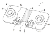
도1은 본 발명에 따른 전류 감응형 저항기의 사시도.
도2는 도1의 전류 감응형 저항기의 평면도.
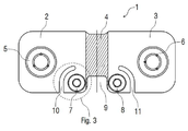
도3은 도1 및 도2의 전류 감응형 저항기의 측면도.
도4는 도2의 전류 감응형 저항기의 상세도.
도5는 전압 접촉점들 사이의 전류선과 등전위선을 갖춘 종래의 전류 감응형 저항기의 평면도.
도6은 종래의 전류 감응형 저항기와 비교된, 본 발명에 따른 전류 감응형 저항기의 저항값의 온도 의존도를 보여주는 다이아그램.
<도면의 주요부분에 대한 부호의 설명>
1: 전류 감응형 저항기 2, 3: 접속부
4: 저항소자 5, 6: 전류 접촉점
7, 8: 전압 접촉점 9, 10, 11: 절개부
12: 전류선 13: 등전위선1 is a perspective view of a current sensitive resistor according to the present invention;
2 is a plan view of the current sensitive resistor of FIG.
3 is a side view of the current sensitive resistor of FIGS. 1 and 2;
4 is a detailed view of the current sensitive resistor of FIG.
5 is a plan view of a conventional current sensitive resistor having current lines and equipotential lines between voltage contact points.
Figure 6 is a diagram showing the temperature dependence of the resistance value of the current sensitive resistor according to the present invention, compared to a conventional current sensitive resistor.
Description of the Related Art
1: current
4:
7, 8:
12: current line 13: equipotential line
이하, 첨부 도면을 참고로 하여 본 발명의 일 실시예를 상세히 설명하기로 한다.
Hereinafter, an embodiment of the present invention will be described in detail with reference to the accompanying drawings.
도1 내지 도4 및 도5B는 본 발명에 따른 전류 감응형 저항기(1)의 대표적인 구현예를 보여주는 것으로, 이것은 예컨대, 모터 차량 온-보드 전기 시스템에서 공지된 4-선 기술에 따라 전류를 측정하는 데 사용되는 것이다.
1-4 and 5B show a representative embodiment of the current-
본 발명에 따른 전류 감응형 저항기(1)는 EP 0 605 800 A1에 기술된 바와 같은 종래의 전류 감응형 저항기와 대부분 상응한 것으로서, 본 출원에서도 이를 토대로 부가적으로 설명된다.
The current
본 발명에 따른 전류 감응형 저항기(1)는 실질적으로 도전재료(이를 테면, 구리)로 된 두개의 평판형 접속부(2, 3)와 저-저항값의 저항재료(이를 테면, Cu84Ni4Mn12)로 되어 상기 양 평판형 접속부(2, 3) 사이에 삽입되는 평판형 저항소자(4)로 구성된다. 여기서, 상기 양 평판형 접속부(2, 3)는 상기 평판형 저항소자(4)의 양측에 배치되어 상기 평판형 저항소자(4)에 용접된다.
The current
또한, 본 발명에 따른 전류 감응형 저항기(1)는 양 평판형 접속부(2, 3)와 전기적 및 기계적으로 접속된 두개의 전류 접촉점(5, 6)을 가지며, 상기 전류 접촉점(6)은 측정될 전류(I)를 도입시키는 데 사용되고, 전류 접촉점(5)은 측정될 전류(I)를 통전시키는 역활을 하며, 이는 특히 도3 측면도로부터 명백하다.
In addition, the current
또한, 본 발명에 따른 전류 감응형 저항기(1)는 양 평판형 접속부(2, 3)와 전기적 및 기계적으로 접속된 두개의 전압 접촉점(7, 8)을 가지며, 상기 두개의 전압 접촉점(7, 8)은 저항소자(4)에 걸쳐 강하하는 전압을 측정하는 기능을 한다. 상기 양 전압 접촉점(7, 8)은 양 평판형 접속부(2, 3)의 저항소자(4)에 아주 근접하여 배치되어 양 평판형 접속부(2, 3)상의 전압 강하에 의한 전압측정의 왜곡을 피하도록 한다.
In addition, the current-
언급되어야 할 것으로, 본 발명에 따른 전류 감응형 저항기(1)는 저항소자(4)의 영역 측면에 절개부(9)를 가져서 제조의 관점에서 크거나 작게 제조하여 전류 감응형 저항기(1)의 원하는 저항값을 계산 또는 조정하여 사용되도록 한다.
It should be mentioned that the current-
그러나, 본 발명에 따른 기능상 중요한 것으로, 각 절개부(10, 11)가 양 평판형 접속부(2, 3)에 배치되어 측정의 온도 의존도를 감소시키도록 한다. 여기서, 양 절개부(10, 11)는 양 평판형 접속부(2 또는 3)의 동일 테두리로부터 내향하여 횡방향으로 연장하여 아치형 방도로 각각의 전압 접촉점(7 또는 8) 둘레에 유도되며, 양 절개부(10, 11)는 도4의 상세도에서 보는 바와 같이 아크각 α![]()
However, functionally important in accordance with the present invention, each ![]()
아울러, 도4의 상세도는 양 절개부(10, 11)가 슬릿형으로 되고 그리고 절개부(10, 11)의 전체 길이에 걸쳐 일정한 폭(b)을 가지는 것을 보여준다.
In addition, the detailed view of FIG. 4 shows that both
양 절개부(10, 11)의 기능은 도5A 및 도5B를 비교할 때 명백한 것으로, 도5A는 종래기술의 전류 감응형 저항기(1)의전류선(12)과 등전위선(13)의 경로를 보여주고, 도5B는 본 발명의 전류 감응형 저항기(1)의 전류선(12)과 등전위선(13)의 경로를 보여준다. 여기서, 전류선(12)은 주 전류방향을 한정하고, 양 절개부(10, 11)는 이 주 전류방향에 대해 일부 횡방향으로 배향되어 전류 경로에 영향을 주도록 한다.
The function of both
상기 비교는 도5A에 따른 종래의 전류 감응형 저항기(1)에 있어 전압 접촉점(7, 8)을 통과하여 주행하는 등전위선(13)이 저항소자(4)의 외부 테두리와 동일한 전위와 정확히는 같지 않다. 이는 전압 접촉점(7, 8) 사이에서 측정된 전압이 평판형 접속부(2, 3)의 도전재료의 비교적 높은 온도 의존도에 의해 영향받을 수 있다는 것을 의미한다.
The comparison shows that in the conventional current
이에 비해, 도5B와 같이 본 발명의 전류 감응형 저항기(1)에 있어, 양 절개부(10, 11)는 전압 접촉점(7, 8)을 통과하여 주행하는 등전위선들이 저항소자(4)의 외부 테두리에 도달하여 동일한 전위로 있도록 하는 방도로 전류선(12)과 등전위선로부터 멀리 떨어져 휘어진다. 전압 측정 중, 오로지 저항소자(4) 상에 강하하는 전압 만이 측정된다. 이것은 평판형 접속부(2, 3)의 도전재료(이를 테면, 구리)가 저항소자(4)의 저항재료(이를 테면, 등록상표 Manganin) 보다 훨씬 더 높은, 비저항에 대한 온도 의존도를 나타내기 때문에 유리하다. 여기서, 등전위선(13)은 평판형 접속부(2, 3)와 저항소자(4) 사이의 용접 테두리에 점근적으로 적용된다.
On the other hand, in the current-
절개부(10, 11)를 갖는 본 발명의 전류 감응형 저항기(1)의 설계는 도6에 도시된 다이아그램에서 알 수 있는 바와 같이 전류 측정 중 온도 의존도에 대해 고려할만한 감소를 유도하는 바, 도6은 온도(T)의 함수로써 저항값(R)의 온도 의존도를 보여준다.
The design of the current
이상과 같이 본 발명을 도면에 도시한 실시예를 참고하여 설명하였으나, 이는 발명을 설명하기 위한 것일 뿐이며 어떠한 경우에도 본 발명을 한정하는 것은 아니다. 본 발명의 진정한 권리범위는 상술한 명세서에 의해서 보다는 첨부된 특허청구범위의 기술적 사상에 의해 결정되어야 한다. 그리고 이들 청구항의 의미 및 균등범위에 속하는 모든 변경 실시예들은 모두 그 범위에 포괄되도록 의도된 것이다.
As described above, the present invention has been described with reference to the embodiments shown in the drawings, but this is only for illustrating the present invention and does not limit the present invention in any case. The true scope of the invention should be determined by the technical spirit of the appended claims rather than by the foregoing specification. And it is intended that all modifications which come within the meaning and range of equivalency of the claims shall be embraced within their scope.
Claims (12)
a) 측정되어질 전류(I)를 유도하기 위한 것으로, 전기도전성 재료로 구성된 평판형 제1 접속부(3),
b) 측정되어질 전류(I)를 내보내기 위한 것으로, 전기도전성 재료로 구성된 평판형 제2 접속부(2),
c) 상기 양 평판형 접속부들 사이의 전류 경로에 접속되어 측정되어질 전류(I)가 관통유동하게 되는 평판형 저항소자(4)를 포함하고,
d) 절개부(10, 11)가 상기 평판형 제1 접속부(3) 및/또는 상기 평판형 제2 접속부(2)중에 배치되어 측정부의 온도 의존도를 감소시키도록 한 것을 특징으로 하는 전류 감응형 저항기(1).
The current sensitive resistor 1 for measuring the current I is
a) a flat plate-shaped first connection 3 made of an electrically conductive material for inducing a current I to be measured,
b) a flat plate-like second connection 2 composed of an electroconductive material, for releasing the current I to be measured,
c) a flat resistor element 4 connected to a current path between the two flat plate connections, through which a current I to be measured flows through;
d) Current-sensitive type, characterized in that the cutouts 10, 11 are arranged in the flat first connection 3 and / or in the flat second connection 2 to reduce the temperature dependence of the measuring section. Resistor (1).
a) 측정되어질 전류(I)가 양 평판형 접속부(2, 3) 사이의 주 전류방향(12)을 따라 유동하고, 그리고
b) 상기 절개부(10, 11)가 적어도 자신의 길이의 일부분이 상기 주 전류방향(12)에 대해 횡방향으로 배향된 것을 특징으로 하는 전류 감응형 저항기(1).
The method of claim 1,
a) the current I to be measured flows along the main current direction 12 between the two planar connections 2, 3, and
b) the current sensitive resistor (1), characterized in that the cutout (10, 11) is at least part of its length oriented transverse to the main current direction (12).
a) 제1 전압 접촉점(8)이 평판형 제1 접속부(3)와 전기적 및 기계적으로 접속되고,
b) 제1 절개부(11)가 평판형 제1 접속부(3)에 배치되고,
c) 제2 전압 접촉점(7)이 평판형 제2 접속부(2)와 전기적 및 기계적으로 접속되고,
d) 제2 절개부(10)가 평판형 제2 접속부(2)에 배치된 것을 특징으로 하는 전류 감응형 저항기(1).
10. A method according to any one of the preceding claims,
a) the first voltage contact point 8 is electrically and mechanically connected to the first plate-shaped connecting portion 3,
b) the first cutout 11 is arranged in the flat plate-shaped first connecting portion 3,
c) the second voltage contact point 7 is electrically and mechanically connected to the second plate-shaped connection part 2;
d) A current sensitive resistor (1), characterized in that a second cutout (10) is arranged in the plate-shaped second connection (2).
a) 평판형 제1 접속부(3)에 있어, 제1 등전위선(13)이 제1 전압 접촉점(7)으로부터 저항소자(4)과의 접촉점까지 주행하여서, 제1 전압 접촉점(7)이 저항소자(4)와의 접촉점과 동일한 전위로 놓이도록 하고, 그리고
b) 평판형 제2 접속부(2)에 있어, 제2 등전위선이 제2 전압 접촉점(8)으로부터 저항소자(4)과의 접촉점까지 주행하여서, 제2 전압 접촉점(8)이 저항소자(4)와의 접촉점과 동일한 전위로 놓이도록 한 것을 특징으로 하는 전류 감응형 저항기(1).
The method of claim 3, wherein
a) In the first flat contact portion 3, the first equipotential line 13 travels from the first voltage contact point 7 to the contact point with the resistance element 4, so that the first voltage contact point 7 resists. To be at the same potential as the point of contact with the element 4, and
b) in the second flat contact portion 2, the second equipotential line travels from the second voltage contact point 8 to the contact point with the resistance element 4, so that the second voltage contact point 8 becomes the resistance element 4; Current-sensitive resistor (1), characterized in that it is placed at the same potential as the point of contact with
a) 제1 접속부(3)의 제1 절개부(11)가 저항소자(4)로부터 떨어져 대면하는 제1 전압 접촉점(8)의 측면상에 배치되고,
b) 제2 접속부(2)의 제2 절개부(10)가 저항소자(4)로부터 떨어져 대면하는 제2 전압 접촉점(7)의 측면상에 배치되는 것을 특징으로 하는 전류 감응형 저항기(1).
The method according to claim 3 or 4,
a) a first cutout 11 of the first connection part 3 is arranged on the side of the first voltage contact point 8 facing away from the resistance element 4,
b) the current sensitive resistor 1, characterized in that the second cutout 10 of the second connection part 2 is arranged on the side of the second voltage contact point 7 facing away from the resistance element 4. .
a) 평판형 제1 접속부(3)의 제1 절개부(11)가 제1 전압 접촉점(8) 둘레에 아치형 또는 각도형 방도로 연장하고, 그리고
b) 평판형 제2 접속부(2)의 제2 절개부(10)가 제2 전압 접촉점(7) 둘레에 아치형 또는 각도형 방도로 연장하는 것을 특징으로 하는 전류 감응형 저항기(1).
6. The method according to any one of claims 3 to 5,
a) the first incision 11 of the first plate-shaped connection 3 extends in an arcuate or angular manner around the first voltage contact point 8, and
b) A current sensitive resistor (1), characterized in that the second cutout (10) of the planar second connection (2) extends in an arcuate or angular manner around the second voltage contact point (7).
a) 절개부(10, 11)가 아크-만곡형으로, 그리고/또는
b) 절개부(10, 11)가 30°, 40°, 50°, 60°또는 70°보다 큰 아크각(α)에 걸쳐 연장하는 것을 특징으로 하는 전류 감응형 저항기(1).
10. A method according to any one of the preceding claims,
a) the incisions 10, 11 are arc-curved and / or
b) Current sensitive resistor (1), characterized in that the cutout (10, 11) extends over an arc angle (α) greater than 30 °, 40 °, 50 °, 60 ° or 70 °.
a) 제1 전류 접촉점(6)이 평판형 제1 접속부(3)와 전기적 그리고 기계적으로 접속되고, 상기 제1 전류 접촉점(6)은 측정되어질 전류(I)를 도입시키는 역활을 하고, 그리고
b) 제2 전류 접촉점(5)이 평판형 제2 접속부(2)와 전기적 그리고 기계적으로 접속되고, 상기 제2 전류 접촉점(5)은 측정되어질 전류(I)를 흘려보내는 역활을 하는 것을 특징으로 하는 전류 감응형 저항기(1).
10. A method according to any one of the preceding claims,
a) a first current contact point 6 is electrically and mechanically connected to the first plate-like connection 3, the first current contact point 6 serves to introduce a current I to be measured, and
b) a second current contact point 5 is electrically and mechanically connected to the plate-shaped second connection part 2, and the second current contact point 5 serves to flow a current I to be measured. Current-sensitive resistor (1).
상기 평판형 접속부(2, 3)의 절개부(10, 11)가 각기 전류 접촉점(5, 6)으로부터 떨어져 만곡되거나 얼마의 각도를 가져 저항소자(4)를 향해진 것을 특징으로 하는 전류 감응형 저항기(1).
9. The method of claim 8,
The cut-out portions 10 and 11 of the plate-shaped connecting portions 2 and 3 are each bent away from the current contact points 5 and 6 or have a certain angle toward the resistance element 4. Resistor (1).
a) 절개부(10, 11)는 그의 길이에 걸쳐 일정한 폭(b)을 가지며, 그리고/또는
b) 절개부(10, 11)는 제 접속부 및/또는 제2 접속부(2)의 테두리로부터 시작하여 내향하여 연장하고, 그리고/또는
c) 적어도 하나의 절개부(10, 11)는 각기 저항소자(4)에 도달하지 않도록 하여 전압 접촉점(7, 8)이 평판형 접속부(2, 3)를 거쳐 그의 전 폭에서 저항소자(4)와 접촉할 수 있도록 한 것을 특징으로 하는 전류 감응형 저항기(1).
10. A method according to any one of the preceding claims,
a) the incisions 10, 11 have a constant width b over their length, and / or
b) the incisions 10, 11 extend inwardly starting from the rim of the first and / or second connection 2, and / or
c) The at least one cutout 10, 11 does not reach the resistive element 4, respectively, so that the voltage contact points 7, 8 pass through the planar connection 2, 3 at their full width. Current-sensitive resistor (1), characterized in that it makes contact with
a) 상기 전류 감응형 저항기(1)는 한정된 온도계수를 가진 한정된 저항값을 가지며, 그리고
b) 상기 저항값의 온도계수는 다른방도로 동일한 평판형 접속부(2, 3)에 절개부(10, 11)가 없는 구성의 전류 감응형 저항기(1)의 것보다 적어도 30%, 40%, 50% 또는 60% 만큼 작은 것을 특징으로 하는 전류 감응형 저항기(1).
10. A method according to any one of the preceding claims,
a) the current sensitive resistor 1 has a finite resistance value with a finite temperature coefficient, and
b) the temperature coefficient of the resistance value is at least 30%, 40%, higher than that of the current-sensitive resistor 1 in the configuration without the cutouts 10, 11 in the same flat connection 2, 3 in different ways; Current-sensitive resistor (1), characterized in that as small as 50% or 60%.
a) 도전재료는 구리 또는 구리합금이고, 그리고/또는
b) 저항재료는 구리합금, 특별하게는 구리-망간-니켈합금, 더 구체적으로는 Cu84Ni4Mn13이고, 그리고/또는
c) 저항소자(4)는 양 접속부(2, 3)와, 상세하게는 용접결합점을 통해 전기적 그리고 기계적으로 접속되며, 그리고/또는
d) 양 접속부(2, 3)는 저항소자(4)의 양측면상에 배치되고, 그리고/또는
e) 평판형 접속부(2, 3) 및/또는 평판형 저항소자(4)는 평탄하거나 만곡된 것을 특징으로 하는 전류 감응형 저항기(1).
10. A method according to any one of the preceding claims,
a) the conductive material is copper or a copper alloy, and / or
b) the resistive material is a copper alloy, in particular a copper-manganese-nickel alloy, more specifically Cu84Ni4Mn13, and / or
c) the resistance element 4 is electrically and mechanically connected to both connections 2 and 3, in particular through a welding point, and / or
d) both connections 2, 3 are arranged on both sides of the resistance element 4 and / or
e) Current sensitive resistor (1), characterized in that the planar connection (2, 3) and / or the planar resistive element (4) are flat or curved.
Applications Claiming Priority (3)
| Application Number | Priority Date | Filing Date | Title |
|---|---|---|---|
| DE102010035485A DE102010035485A1 (en) | 2010-08-26 | 2010-08-26 | Current sense resistor |
| DE102010035485.6 | 2010-08-26 | ||
| PCT/EP2011/004245 WO2012019784A1 (en) | 2010-08-26 | 2011-08-24 | Current-sensing resistor |
Publications (2)
| Publication Number | Publication Date |
|---|---|
| KR20130106830A true KR20130106830A (en) | 2013-09-30 |
| KR101887405B1 KR101887405B1 (en) | 2018-09-11 |
Family
ID=44653244
Family Applications (1)
| Application Number | Title | Priority Date | Filing Date |
|---|---|---|---|
| KR1020137007432A Active KR101887405B1 (en) | 2010-08-26 | 2011-08-24 | Current-sensing resistor |
Country Status (8)
| Country | Link |
|---|---|
| US (1) | US8884733B2 (en) |
| EP (1) | EP2446449B1 (en) |
| JP (1) | JP2013536424A (en) |
| KR (1) | KR101887405B1 (en) |
| CN (1) | CN103180916B (en) |
| DE (1) | DE102010035485A1 (en) |
| ES (1) | ES2684111T3 (en) |
| WO (1) | WO2012019784A1 (en) |
Cited By (1)
| Publication number | Priority date | Publication date | Assignee | Title |
|---|---|---|---|---|
| US10539623B2 (en) | 2016-03-07 | 2020-01-21 | Lg Chem, Ltd. | Charging/discharging current estimation device |
Families Citing this family (46)
| Publication number | Priority date | Publication date | Assignee | Title |
|---|---|---|---|---|
| KR102115114B1 (en) * | 2009-09-04 | 2020-05-25 | 비쉐이 데일 일렉트로닉스, 엘엘씨 | Resistor with temperature coefficient of resistance(tcr) compensation |
| DE102012013036B4 (en) * | 2012-06-29 | 2015-04-02 | Isabellenhütte Heusler Gmbh & Co. Kg | Resistance, in particular low-impedance current measuring resistor, and coating method for this purpose |
| US9523720B2 (en) * | 2013-03-15 | 2016-12-20 | Infineon Technologies Ag | Multiple current sensor device, a multiple current shunt device and a method for providing a sensor signal |
| JP6417756B2 (en) * | 2014-07-02 | 2018-11-07 | 株式会社ジェイテクト | Current detector |
| CN106662603B (en) * | 2014-09-25 | 2019-12-13 | 三洋电机株式会社 | Current detection device and power supply unit with shunt resistor |
| JP6714974B2 (en) * | 2015-05-19 | 2020-07-01 | Koa株式会社 | Current detector |
| JP6795879B2 (en) * | 2015-06-15 | 2020-12-02 | Koa株式会社 | Resistor and its manufacturing method |
| EP3115798A1 (en) * | 2015-07-10 | 2017-01-11 | Continental Automotive GmbH | Battery sensor unit with resistance element |
| CN107923952A (en) * | 2015-08-14 | 2018-04-17 | 大陆汽车有限公司 | Battery sensor units with high mechanical robustness |
| JP6695122B2 (en) * | 2015-10-15 | 2020-05-20 | サンコール株式会社 | Manufacturing method of shunt resistor |
| DE102015226665A1 (en) * | 2015-12-23 | 2017-06-29 | Robert Bosch Gmbh | Electrically conductive measuring layer for measuring a potential difference |
| JP6942438B2 (en) * | 2016-03-18 | 2021-09-29 | ローム株式会社 | Shunt resistor |
| JP6400051B2 (en) * | 2016-07-12 | 2018-10-03 | Koa株式会社 | Shunt resistance type current detector |
| DE102017203535A1 (en) | 2017-03-03 | 2018-09-06 | Continental Automotive Gmbh | Current sensor with optimized current density distribution, method for determining a load current |
| DE102017207713A1 (en) | 2017-05-08 | 2018-11-08 | Robert Bosch Gmbh | Shunt resistor for detecting the state of an electrical energy storage unit |
| WO2018229817A1 (en) * | 2017-06-12 | 2018-12-20 | 新電元工業株式会社 | Power module |
| US10438730B2 (en) * | 2017-10-31 | 2019-10-08 | Cyntec Co., Ltd. | Current sensing resistor and fabrication method thereof |
| KR101856670B1 (en) | 2017-12-12 | 2018-05-15 | (주)서준전기 | A bus bar for a distribution board capable of measuring a current by combining a shunt resistor and a method of manufacturing the same, and a bus bar module |
| CN108565082A (en) * | 2018-04-16 | 2018-09-21 | 张照亮 | Microhm current sense resistor |
| EP3853620B1 (en) * | 2018-09-21 | 2023-11-08 | Continental Automotive Technologies GmbH | Battery sensor for temperature-independent current measurement using a shunt |
| EP3664269A1 (en) * | 2018-12-07 | 2020-06-10 | Siemens Aktiengesellschaft | Measuring shunt |
| US11415601B2 (en) * | 2018-12-21 | 2022-08-16 | Cyntec Co., Ltd. | Resistor having low temperature coefficient of resistance |
| CN109975614B (en) * | 2019-02-18 | 2021-02-23 | 南京隆特集成电路科技有限公司 | Four-wire current sensing resistor and measuring method thereof |
| JP7210335B2 (en) * | 2019-03-08 | 2023-01-23 | サンコール株式会社 | Shunt resistor and its manufacturing method |
| WO2021100084A1 (en) | 2019-11-18 | 2021-05-27 | サンコール株式会社 | Shunt resistor |
| JP7491723B2 (en) | 2020-04-20 | 2024-05-28 | Koa株式会社 | Shunt Resistor |
| JP7491727B2 (en) * | 2020-04-28 | 2024-05-28 | Koa株式会社 | Shunt Resistor |
| DE102020111634B3 (en) * | 2020-04-29 | 2021-04-01 | Isabellenhütte Heusler Gmbh & Co. Kg | Current sense resistor |
| DE102020118637B3 (en) * | 2020-07-15 | 2022-01-13 | Isabellenhütte Heusler Gmbh & Co. Kg | Current measuring device with redundant current measurement |
| JP7567261B2 (en) * | 2020-07-31 | 2024-10-16 | 株式会社デンソー | Current Detector |
| EP3958002B1 (en) * | 2020-08-20 | 2024-03-13 | TE Connectivity Germany GmbH | Current sensor element, current sensor unit, and method of measuring a current |
| KR102575337B1 (en) * | 2020-08-20 | 2023-09-06 | 비쉐이 데일 일렉트로닉스, 엘엘씨 | Resistors, Current Sense Resistors, Battery Shunts, Shunt Resistors, and Methods of Manufacturing |
| JP7606842B2 (en) | 2020-09-30 | 2024-12-26 | Koa株式会社 | Shunt resistor device and method for adjusting characteristics of current detection shunt resistor device |
| DE102020214083A1 (en) * | 2020-11-10 | 2022-05-12 | Continental Automotive Gmbh | Resistor assembly and battery sensor with resistor assembly |
| EP4012428B1 (en) * | 2020-12-09 | 2023-06-07 | Continental Automotive Technologies GmbH | Resistor element and method for producing a resistor element |
| DE102020007556A1 (en) | 2020-12-10 | 2022-06-15 | Wieland-Werke Aktiengesellschaft | Resistor arrangement and method for its manufacture |
| DE102021103238A1 (en) | 2021-02-11 | 2022-08-11 | Isabellenhütte Heusler Gmbh & Co. Kg | current sensing resistor |
| WO2022171439A1 (en) | 2021-02-11 | 2022-08-18 | Isabellenhütte Heusler Gmbh & Co. Kg | Current-sensing resistor |
| DE102021103241A1 (en) | 2021-02-11 | 2022-08-11 | Isabellenhütte Heusler Gmbh & Co. Kg | current sensing resistor |
| USD1069711S1 (en) | 2021-05-11 | 2025-04-08 | Vishay Dale Electronics, Llc | Resistor |
| JP7627172B2 (en) * | 2021-05-18 | 2025-02-05 | Koa株式会社 | Current Detector |
| DE102021117637A1 (en) | 2021-07-08 | 2023-01-12 | Preh Gmbh | Measuring resistor for measuring electrical current, associated manufacturing process and current sensor containing the measuring resistor |
| DE102021122491B4 (en) * | 2021-08-31 | 2023-03-30 | Isabellenhütte Heusler Gmbh & Co. Kg | current sensing resistor |
| JP2023087730A (en) * | 2021-12-14 | 2023-06-26 | Koa株式会社 | Shunt resistors and current sensing devices |
| JP7783770B2 (en) * | 2022-03-28 | 2025-12-10 | Koa株式会社 | Current detection device |
| US12068092B2 (en) * | 2022-04-08 | 2024-08-20 | Cyntec Co., Ltd. | Structure of resistor device and system for measuring resistance of same |
Citations (1)
| Publication number | Priority date | Publication date | Assignee | Title |
|---|---|---|---|---|
| JP2002519672A (en) * | 1998-06-30 | 2002-07-02 | デルタ・エレクトリカル・リミテッド | Current detector and current measuring device having such a detector |
Family Cites Families (15)
| Publication number | Priority date | Publication date | Assignee | Title |
|---|---|---|---|---|
| DE2939594A1 (en) * | 1979-09-29 | 1981-04-09 | Robert Bosch Gmbh, 7000 Stuttgart | High current electrical measurement resistance - with stamped and punched resistance path and current connections and welded tappings |
| JPH0483175A (en) * | 1990-07-25 | 1992-03-17 | Mitsubishi Electric Corp | current detection device |
| DE4243349A1 (en) | 1992-12-21 | 1994-06-30 | Heusler Isabellenhuette | Manufacture of resistors from composite material |
| US5999085A (en) * | 1998-02-13 | 1999-12-07 | Vishay Dale Electronics, Inc. | Surface mounted four terminal resistor |
| JP3955739B2 (en) | 2001-03-27 | 2007-08-08 | 多摩電気工業株式会社 | Resistor manufacturing method |
| JP2003232814A (en) | 2002-02-06 | 2003-08-22 | Toshiba Corp | Current detecting device and current detecting device for inverter |
| US20040216303A1 (en) * | 2003-05-01 | 2004-11-04 | Berlin Carl W. | Thick film current sensing resistor and method |
| JP2007221006A (en) * | 2006-02-17 | 2007-08-30 | Sanken Electric Co Ltd | Resistor including resistance element and method of resistance value inspection performed by resistor |
| US7911319B2 (en) * | 2008-02-06 | 2011-03-22 | Vishay Dale Electronics, Inc. | Resistor, and method for making same |
| JP2009204531A (en) * | 2008-02-28 | 2009-09-10 | Sanyo Electric Co Ltd | Shunt resistor, and power supply device for vehicle equipped with the shunt resistor |
| JP5263733B2 (en) * | 2008-04-24 | 2013-08-14 | コーア株式会社 | Metal plate resistor |
| FR2946203B1 (en) * | 2009-05-28 | 2016-07-29 | Ixmotion | METHOD AND APPARATUS FOR MITIGATING NARROW BANDOISE NOISE IN A VEHICLE HABITACLE |
| DE102009031408A1 (en) | 2009-07-01 | 2011-01-05 | Isabellenhütte Heusler Gmbh & Co. Kg | Electronic component and corresponding manufacturing method |
| KR102115114B1 (en) * | 2009-09-04 | 2020-05-25 | 비쉐이 데일 일렉트로닉스, 엘엘씨 | Resistor with temperature coefficient of resistance(tcr) compensation |
| TWI428940B (en) * | 2011-11-15 | 2014-03-01 | Ta I Technology Co Ltd | Current sensing resistor and method for manufacturing the same |
-
2010
- 2010-08-26 DE DE102010035485A patent/DE102010035485A1/en not_active Withdrawn
-
2011
- 2011-08-24 WO PCT/EP2011/004245 patent/WO2012019784A1/en not_active Ceased
- 2011-08-24 CN CN201180051101.6A patent/CN103180916B/en active Active
- 2011-08-24 US US13/819,020 patent/US8884733B2/en active Active
- 2011-08-24 KR KR1020137007432A patent/KR101887405B1/en active Active
- 2011-08-24 EP EP11757765.0A patent/EP2446449B1/en active Active
- 2011-08-24 ES ES11757765.0T patent/ES2684111T3/en active Active
- 2011-08-24 JP JP2013525182A patent/JP2013536424A/en active Pending
Patent Citations (1)
| Publication number | Priority date | Publication date | Assignee | Title |
|---|---|---|---|---|
| JP2002519672A (en) * | 1998-06-30 | 2002-07-02 | デルタ・エレクトリカル・リミテッド | Current detector and current measuring device having such a detector |
Cited By (1)
| Publication number | Priority date | Publication date | Assignee | Title |
|---|---|---|---|---|
| US10539623B2 (en) | 2016-03-07 | 2020-01-21 | Lg Chem, Ltd. | Charging/discharging current estimation device |
Also Published As
| Publication number | Publication date |
|---|---|
| US20130181807A1 (en) | 2013-07-18 |
| US8884733B2 (en) | 2014-11-11 |
| JP2013536424A (en) | 2013-09-19 |
| CN103180916B (en) | 2016-08-03 |
| ES2684111T3 (en) | 2018-10-01 |
| EP2446449A1 (en) | 2012-05-02 |
| DE102010035485A1 (en) | 2012-03-01 |
| CN103180916A (en) | 2013-06-26 |
| EP2446449B1 (en) | 2018-06-13 |
| WO2012019784A1 (en) | 2012-02-16 |
| KR101887405B1 (en) | 2018-09-11 |
Similar Documents
| Publication | Publication Date | Title |
|---|---|---|
| KR20130106830A (en) | Current-sensing resistor | |
| US12135340B2 (en) | Current detection device with voltage detecting portion positioning | |
| US12372555B2 (en) | Current-sensing resistor | |
| CN103180741B (en) | Connection terminal for shunt resistor and battery status detection device | |
| JP7609889B2 (en) | Current Sense Resistor | |
| JP6384211B2 (en) | Shunt resistor | |
| US20200200799A1 (en) | Resistor having low temperature coefficient of resistance | |
| JP2013536424A5 (en) | ||
| US12249445B2 (en) | Shunt resistor | |
| US20230081784A1 (en) | Resistor arrangement | |
| US20240248119A1 (en) | Current detection device | |
| WO2019097925A1 (en) | Shunt resistor | |
| US12080453B2 (en) | Shunt resistor | |
| CN116264120B (en) | Shunt resistor and current detection device | |
| CN113077950A (en) | Resistor with a resistor element | |
| JP6689510B2 (en) | Battery cell assembly | |
| US20240085459A1 (en) | Current-sensing resistor | |
| JP5445193B2 (en) | Resistor, mounting method of resistor, measuring method of resistor | |
| CN107923952A (en) | Battery sensor units with high mechanical robustness | |
| CN222887812U (en) | Resistors and power supply devices for current detection | |
| CN219066527U (en) | Resistor and power supply device for detecting current | |
| JP2023083751A (en) | Resistor |
Legal Events
| Date | Code | Title | Description |
|---|---|---|---|
| PA0105 | International application |
St.27 status event code: A-0-1-A10-A15-nap-PA0105 |
|
| PG1501 | Laying open of application |
St.27 status event code: A-1-1-Q10-Q12-nap-PG1501 |
|
| PA0201 | Request for examination |
St.27 status event code: A-1-2-D10-D11-exm-PA0201 |
|
| D13-X000 | Search requested |
St.27 status event code: A-1-2-D10-D13-srh-X000 |
|
| D14-X000 | Search report completed |
St.27 status event code: A-1-2-D10-D14-srh-X000 |
|
| E902 | Notification of reason for refusal | ||
| PE0902 | Notice of grounds for rejection |
St.27 status event code: A-1-2-D10-D21-exm-PE0902 |
|
| E13-X000 | Pre-grant limitation requested |
St.27 status event code: A-2-3-E10-E13-lim-X000 |
|
| P11-X000 | Amendment of application requested |
St.27 status event code: A-2-2-P10-P11-nap-X000 |
|
| P13-X000 | Application amended |
St.27 status event code: A-2-2-P10-P13-nap-X000 |
|
| E701 | Decision to grant or registration of patent right | ||
| PE0701 | Decision of registration |
St.27 status event code: A-1-2-D10-D22-exm-PE0701 |
|
| GRNT | Written decision to grant | ||
| PR0701 | Registration of establishment |
St.27 status event code: A-2-4-F10-F11-exm-PR0701 |
|
| PR1002 | Payment of registration fee |
St.27 status event code: A-2-2-U10-U12-oth-PR1002 Fee payment year number: 1 |
|
| PG1601 | Publication of registration |
St.27 status event code: A-4-4-Q10-Q13-nap-PG1601 |
|
| PR1001 | Payment of annual fee |
St.27 status event code: A-4-4-U10-U11-oth-PR1001 Fee payment year number: 4 |
|
| PR1001 | Payment of annual fee |
St.27 status event code: A-4-4-U10-U11-oth-PR1001 Fee payment year number: 5 |
|
| PR1001 | Payment of annual fee |
St.27 status event code: A-4-4-U10-U11-oth-PR1001 Fee payment year number: 6 |
|
| PR1001 | Payment of annual fee |
St.27 status event code: A-4-4-U10-U11-oth-PR1001 Fee payment year number: 7 |
|
| PR1001 | Payment of annual fee |
St.27 status event code: A-4-4-U10-U11-oth-PR1001 Fee payment year number: 8 |
|
| U11 | Full renewal or maintenance fee paid |
Free format text: ST27 STATUS EVENT CODE: A-4-4-U10-U11-OTH-PR1001 (AS PROVIDED BY THE NATIONAL OFFICE) Year of fee payment: 8 |