KR20140029384A - 유체 감압 프로세스 및 이 목적에 적합한 기기 - Google Patents
유체 감압 프로세스 및 이 목적에 적합한 기기 Download PDFInfo
- Publication number
- KR20140029384A KR20140029384A KR1020137019811A KR20137019811A KR20140029384A KR 20140029384 A KR20140029384 A KR 20140029384A KR 1020137019811 A KR1020137019811 A KR 1020137019811A KR 20137019811 A KR20137019811 A KR 20137019811A KR 20140029384 A KR20140029384 A KR 20140029384A
- Authority
- KR
- South Korea
- Prior art keywords
- fluid
- duct
- pressure
- separator
- extraction
- Prior art date
- Legal status (The legal status is an assumption and is not a legal conclusion. Google has not performed a legal analysis and makes no representation as to the accuracy of the status listed.)
- Granted
Links
Images




Classifications
-
- B—PERFORMING OPERATIONS; TRANSPORTING
- B01—PHYSICAL OR CHEMICAL PROCESSES OR APPARATUS IN GENERAL
- B01D—SEPARATION
- B01D19/00—Degasification of liquids
- B01D19/0042—Degasification of liquids modifying the liquid flow
-
- B—PERFORMING OPERATIONS; TRANSPORTING
- B01—PHYSICAL OR CHEMICAL PROCESSES OR APPARATUS IN GENERAL
- B01D—SEPARATION
- B01D19/00—Degasification of liquids
-
- B—PERFORMING OPERATIONS; TRANSPORTING
- B01—PHYSICAL OR CHEMICAL PROCESSES OR APPARATUS IN GENERAL
- B01D—SEPARATION
- B01D19/00—Degasification of liquids
- B01D19/0042—Degasification of liquids modifying the liquid flow
- B01D19/0052—Degasification of liquids modifying the liquid flow in rotating vessels, vessels containing movable parts or in which centrifugal movement is caused
- B01D19/0057—Degasification of liquids modifying the liquid flow in rotating vessels, vessels containing movable parts or in which centrifugal movement is caused the centrifugal movement being caused by a vortex, e.g. using a cyclone, or by a tangential inlet
Landscapes
- Chemical & Material Sciences (AREA)
- Chemical Kinetics & Catalysis (AREA)
- Physical Or Chemical Processes And Apparatus (AREA)
- Apparatus For Radiation Diagnosis (AREA)
- Vaporization, Distillation, Condensation, Sublimation, And Cold Traps (AREA)
- Cyclones (AREA)
- Pipeline Systems (AREA)
- Feeding, Discharge, Calcimining, Fusing, And Gas-Generation Devices (AREA)
Abstract
Description
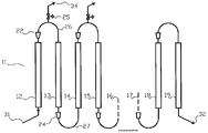
도 2 는 본 발명의 기기의 실시형태를 도시한다.
도 3 은 분리 기기를 사용하는 본 발명의 실시형태를 도시한다.
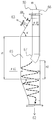
도 4 및 도 5 는 전술한 실시형태와 사용될 상 분리기의 실시예를 도시한다.
도 6 은 필터링의 수행 방법에 대한 실시예를 도시한다.
도 7 은 필터링 요소의 실시형태 예를 도시한다.
Claims (20)
- 적어도 하나의 액체상을 함유한 유체의 압력을 감소시키는 방법으로서,
감압될 유체를 제 1 하부 커넥터들에 의하여 직렬로 (in series) 연결된 복수의 스텝들을 통하여 순차적으로 통과시키는 것을 포함하고, 각각의 상기 스텝은 제 2 상부 커넥터들에 의하여 상부에서 연결된 한 쌍의 수직 덕트들로 이루어지고,
상기 유체는 아래에서 위로 각 스텝의 제 1 덕트를 통과하고, 위에서 아래로 상기 각 스텝의 제 2 덕트를 통과하고, 상기 각 스텝의 상기 제 1 덕트에서는, 상기 유체의 압력 에너지의 일부가 중력 퍼텐셜 (potential) 로 전환되는 한편, 상기 제 2 덕트에서는, 상기 중력 퍼텐셜의 일부가 열 에너지로 전환되는, 유체의 압력을 감소시키는 방법. - 제 1 항에 있어서,
가스상을 함유한 유체의 도입 또는 제거는 상기 각 스텝의 상기 제 1 덕트와 상기 제 2 덕트 사이에서 조정되는, 유체의 압력을 감소시키는 방법. - 제 1 항 또는 제 2 항에 있어서,
상기 감압될 유체는 고체상을 또한 함유하는, 유체의 압력을 감소시키는 방법. - 제 1 항 내지 제 3 항 중 어느 한 항에 있어서,
감압 공급될 유체는, 입구 압력에서 측정된, 0.01 보다 높은 가스 유량과 액체 유량 사이의 체적비를 갖는 가스상을 또한 포함하는, 유체의 압력을 감소시키는 방법. - 제 1 항 내지 제 3 항 중 어느 한 항에 있어서,
입구 압력에서, 가스 유량과 액체 유량 사이의 체적비는 0 ~ 2 이고,
상기 제 1 스텝의 상기 제 1 덕트와 상기 제 2 덕트 사이에 가스 유체가 도입되는, 유체의 압력을 감소시키는 방법. - 제 1 항 내지 제 5 항 중 어느 한 항에 있어서,
적어도 하나의 스텝의 상기 제 1 덕트와 상기 제 2 덕트 사이에서, 유동이 추출되고, 상기 유동의 가스 성분은 추출된 유량에 대해 적어도 50 % 의 체적 유량을 가지는, 유체의 압력을 감소시키는 방법. - 제 6 항에 있어서,
상기 유체의 추출은 상기 스텝의 상기 제 1 덕트와 상기 제 2 덕트 사이에 위치결정된 상 분리기에서 수행되는, 유체의 압력을 감소시키는 방법. - 제 6 항 또는 제 7 항에 있어서,
상기 유동의 추출은, 상기 추출이 수행되는 동일한 스텝의 상기 제 2 덕트의 하단부와 상단부 사이에서 측정된 압력 차이에 대해 피드백 조정되는, 유체의 압력을 감소시키는 방법. - 제 7 항에 있어서,
상기 유동의 추출은, 상기 추출이 수행되는 동일한 스텝의 상 분리기와 후속 스텝의 분리기 사이에서 측정된 압력 차이에 대해 피드백 조정되는, 유체의 압력을 감소시키는 방법. - 제 1 항 내지 제 9 항 중 어느 한 항에 있어서,
공급된 유체는 열가소성 폴리머용 과립기 (granulator) 로부터 유래하는, 유체의 압력을 감소시키는 방법. - 제 1 항 내지 제 10 항 중 어느 한 항에 있어서,
상기 제 2 덕트는 상기 제 1 덕트에 대해 더 큰 직경을 가지는, 유체의 압력을 감소시키는 방법. - 제 1 항 내지 제 11 항 중 어느 한 항에 있어서,
상기 스텝들의 개수는 2 ~ 500 개인, 유체의 압력을 감소시키는 방법. - 제 12 항에 있어서,
상기 스텝들의 개수는 2 ~ 50 개인, 유체의 압력을 감소시키는 방법. - 제 13 항에 있어서,
상기 스텝들의 개수는 2 ~ 10 개인, 유체의 압력을 감소시키는 방법. - 제 1 항 내지 제 14 항 중 어느 한 항에 따른 방법에 따라 유체를 감압하는 기기로서,
제 1 하부 커넥터들에 의하여 직렬로 연결된 복수의 스텝들을 포함하고, 각각의 스텝은 제 2 커넥터들에 의하여 상부에서 연결된 한 쌍의 수직 덕트들로 이루어지고,
상기 유체는 각각의 스텝의 제 1 덕트에서 아래에서부터 위로 전달되고, 상기 각각의 스텝의 제 2 덕트에서 위에서부터 아래로 전달되는, 유체를 감압하는 기기. - 제 15 항에 있어서,
적어도 하나의 스텝의 2 개의 덕트들 사이에 위치하는, 하나 이상의 가스 삽입 수단 및/또는 하나 이상의 유체 추출 수단을 더 포함하는, 유체를 감압하는 기기. - 제 16 항에 있어서,
상기 유체 추출은 상기 스텝의 상기 제 1 덕트와 상기 제 2 덕트 사이에 위치하는 상 분리기에서 수행되는, 유체를 감압하는 기기. - 제 17 항에 있어서,
상기 분리기는 적어도 2 개의 인접한 보디들, 즉 유체 단면적이 상기 스텝의 상기 제 1 덕트의 단면적에 대해 적어도 50 % 만큼 증가된 제 1 보디, 유체 단면적이 상기 스텝의 상기 제 2 덕트의 단면적으로 복구된 제 2 보디, 및 가능하게는 상기 제 1 보디와 상기 제 2 보디를 연결하는 중간 보디로 이루어지고,
상기 유체 추출은 상기 분리기의 외벽에 위치한 노즐을 통하여 얻어지는, 유체를 감압하는 기기. - 제 18 항에 있어서,
상기 유체는, 상기 유체를 상기 중간 보디 내로 직접 운반하는 텔레스코프 (telescope) 에 의하여 상기 분리기에 공급되는, 유체를 감압하는 기기. - 제 19 항에 있어서,
상기 텔레스코프에서 나온 유체는, 상기 분리기의 측벽에 대해 접선 방향으로 상기 분리기에 공급되는, 유체를 감압하는 기기.
Applications Claiming Priority (3)
| Application Number | Priority Date | Filing Date | Title |
|---|---|---|---|
| ITMI2010A002429A IT1404150B1 (it) | 2010-12-28 | 2010-12-28 | Procedimento per la depressurizzazione di fluidi e dispositivo adatto allo scopo |
| ITMI2010A002429 | 2010-12-28 | ||
| PCT/IB2011/055987 WO2012090166A2 (en) | 2010-12-28 | 2011-12-28 | Process for the depressurization of fluids and device suitable for the purpose |
Publications (2)
| Publication Number | Publication Date |
|---|---|
| KR20140029384A true KR20140029384A (ko) | 2014-03-10 |
| KR101961963B1 KR101961963B1 (ko) | 2019-03-25 |
Family
ID=43737081
Family Applications (1)
| Application Number | Title | Priority Date | Filing Date |
|---|---|---|---|
| KR1020137019811A Expired - Fee Related KR101961963B1 (ko) | 2010-12-28 | 2011-12-28 | 유체 감압 프로세스 및 이 목적에 적합한 기기 |
Country Status (14)
| Country | Link |
|---|---|
| US (1) | US9403105B2 (ko) |
| EP (1) | EP2658628B1 (ko) |
| JP (1) | JP5981450B2 (ko) |
| KR (1) | KR101961963B1 (ko) |
| CN (1) | CN103889531B (ko) |
| BR (1) | BR112013016340A2 (ko) |
| ES (1) | ES2899498T3 (ko) |
| HU (1) | HUE057235T2 (ko) |
| IT (1) | IT1404150B1 (ko) |
| MX (1) | MX350994B (ko) |
| MY (1) | MY173383A (ko) |
| PL (1) | PL2658628T3 (ko) |
| RU (1) | RU2596740C2 (ko) |
| WO (1) | WO2012090166A2 (ko) |
Families Citing this family (1)
| Publication number | Priority date | Publication date | Assignee | Title |
|---|---|---|---|---|
| US10443586B1 (en) | 2018-09-12 | 2019-10-15 | Douglas A Sahm | Fluid transfer and depressurization system |
Citations (3)
| Publication number | Priority date | Publication date | Assignee | Title |
|---|---|---|---|---|
| US6429268B1 (en) * | 1998-04-28 | 2002-08-06 | Heriot-Watt University | Method and apparatus for phase separated synthesis |
| WO2008122812A2 (en) * | 2007-04-10 | 2008-10-16 | Nitech Solutions Limited | Tubular mixing apparatus and method |
| JP2008246370A (ja) * | 2007-03-30 | 2008-10-16 | Toyota Motor Corp | 気液分離装置 |
Family Cites Families (26)
| Publication number | Priority date | Publication date | Assignee | Title |
|---|---|---|---|---|
| US3792067A (en) * | 1971-06-10 | 1974-02-12 | Blaw Knox Chem Plants Inc | Continuous hydrogenation of fatty materials |
| JPS54106506A (en) * | 1978-02-08 | 1979-08-21 | Yamagata Daigakuchiyou | Coal direct liquefication reaction method and apparatus |
| US4515629A (en) * | 1981-02-12 | 1985-05-07 | United Technologies Corporation | Degassing metal powder |
| US5036909A (en) * | 1989-06-22 | 1991-08-06 | General Motors Corporation | Multiple serpentine tube heat exchanger |
| US4923166A (en) | 1989-07-28 | 1990-05-08 | Red Valve Company, Inc. | Pressure-reducing noise-abating control valve |
| JP2586561Y2 (ja) * | 1993-01-27 | 1998-12-09 | トヨタ車体株式会社 | 高粘性液体の減圧装置 |
| FR2731781B1 (fr) * | 1995-03-15 | 1997-05-23 | Air Liquide | Procede et appareil de vaporisation d'un debit liquide |
| DE19827852A1 (de) * | 1998-06-23 | 1999-12-30 | Bayer Ag | Verfahren zur Isolierung von Polymeren aus Lösungen |
| US6036751A (en) * | 1998-08-04 | 2000-03-14 | Ribardi; Harris J. | System for depressurizing, filtering, and noise suppression of high pressure pneumatic vessels |
| JP2002166404A (ja) * | 2000-11-29 | 2002-06-11 | Ibiden Co Ltd | セラミック構造体の製造方法 |
| WO2003018189A1 (en) * | 2001-08-29 | 2003-03-06 | Nippon Sanso Corporation | Adsorbent for separating nitrogen from mixed gas of oxygen and nitrogen |
| ITMI20012708A1 (it) | 2001-12-20 | 2003-06-20 | Enichem Spa | Dispositivo per la granulazione a caldo di polimeri termolastici |
| DE10226749B4 (de) | 2002-06-14 | 2014-09-04 | Basf Se | Verfahren zur Herstellung von expandierbarem Polystyrol |
| US6929680B2 (en) * | 2003-09-26 | 2005-08-16 | Consortium Services Management Group, Inc. | CO2 separator method and apparatus |
| US7491261B2 (en) * | 2005-06-27 | 2009-02-17 | Wearair Oxygen, Inc. | Process and apparatus for generating and delivering an enriched gas fraction |
| US20070170611A1 (en) | 2006-01-26 | 2007-07-26 | Andrew Steven Hudson | Start-up procedure for underwater pelletizer |
| US7267540B2 (en) | 2006-01-26 | 2007-09-11 | Gala Industries, Inc. | Steep angle cutter hub with blunt edge blades |
| EP1998948B2 (de) | 2006-03-22 | 2017-06-07 | Basf Se | Verfahren und vorrichtung zur granulierung von treibmittelhaltigen polymerschmelzen |
| JP2007268406A (ja) | 2006-03-31 | 2007-10-18 | Mitsui Eng & Shipbuild Co Ltd | 脱圧装置およびガスハイドレートの製造装置 |
| US7802592B2 (en) | 2006-04-18 | 2010-09-28 | Fisher Controls International, Llc | Fluid pressure reduction devices |
| DE102006022555B4 (de) | 2006-05-15 | 2010-12-16 | Rieter Automatik Gmbh | Vorrichtung und Verfahren zur Erzeugung eines Granulats aus einer Kunststoffschmelze |
| JP4966699B2 (ja) * | 2007-03-19 | 2012-07-04 | 東京瓦斯株式会社 | フランジ配管接続部の補修工法及び補修用治具 |
| KR100896455B1 (ko) * | 2007-07-09 | 2009-05-14 | 한국에너지기술연구원 | 압력변동흡착장치 및 이를 이용한 수소 정제 방법 |
| NO329468B1 (no) | 2009-01-07 | 2010-10-25 | Framo Eng As | Anordning for tilveiebringelse av en kontrollerbar trykkreduksjon. |
| GB201117064D0 (en) * | 2011-10-04 | 2011-11-16 | Univ Brunel | A modular flow reactor |
| JP5902920B2 (ja) * | 2011-11-10 | 2016-04-13 | 大陽日酸株式会社 | 窒素ガス製造方法、ガス分離方法および窒素ガス製造装置 |
-
2010
- 2010-12-28 IT ITMI2010A002429A patent/IT1404150B1/it active
-
2011
- 2011-12-28 JP JP2013546812A patent/JP5981450B2/ja not_active Expired - Fee Related
- 2011-12-28 PL PL11820808T patent/PL2658628T3/pl unknown
- 2011-12-28 ES ES11820808T patent/ES2899498T3/es active Active
- 2011-12-28 US US13/976,345 patent/US9403105B2/en not_active Expired - Fee Related
- 2011-12-28 CN CN201180062893.7A patent/CN103889531B/zh not_active Expired - Fee Related
- 2011-12-28 RU RU2013134995/05A patent/RU2596740C2/ru active
- 2011-12-28 EP EP11820808.1A patent/EP2658628B1/en active Active
- 2011-12-28 WO PCT/IB2011/055987 patent/WO2012090166A2/en not_active Ceased
- 2011-12-28 KR KR1020137019811A patent/KR101961963B1/ko not_active Expired - Fee Related
- 2011-12-28 MX MX2013007522A patent/MX350994B/es active IP Right Grant
- 2011-12-28 HU HUE11820808A patent/HUE057235T2/hu unknown
- 2011-12-28 BR BR112013016340-2A patent/BR112013016340A2/pt not_active Application Discontinuation
- 2011-12-28 MY MYPI2013002449A patent/MY173383A/en unknown
Patent Citations (3)
| Publication number | Priority date | Publication date | Assignee | Title |
|---|---|---|---|---|
| US6429268B1 (en) * | 1998-04-28 | 2002-08-06 | Heriot-Watt University | Method and apparatus for phase separated synthesis |
| JP2008246370A (ja) * | 2007-03-30 | 2008-10-16 | Toyota Motor Corp | 気液分離装置 |
| WO2008122812A2 (en) * | 2007-04-10 | 2008-10-16 | Nitech Solutions Limited | Tubular mixing apparatus and method |
Also Published As
| Publication number | Publication date |
|---|---|
| MY173383A (en) | 2020-01-21 |
| US9403105B2 (en) | 2016-08-02 |
| WO2012090166A2 (en) | 2012-07-05 |
| CN103889531B (zh) | 2016-04-27 |
| WO2012090166A3 (en) | 2014-04-10 |
| CN103889531A (zh) | 2014-06-25 |
| HUE057235T2 (hu) | 2022-04-28 |
| IT1404150B1 (it) | 2013-11-15 |
| MX2013007522A (es) | 2014-03-05 |
| US20130333558A1 (en) | 2013-12-19 |
| ES2899498T3 (es) | 2022-03-11 |
| RU2013134995A (ru) | 2015-02-10 |
| PL2658628T3 (pl) | 2022-01-31 |
| BR112013016340A2 (pt) | 2020-12-01 |
| EP2658628A2 (en) | 2013-11-06 |
| JP2014514504A (ja) | 2014-06-19 |
| RU2596740C2 (ru) | 2016-09-10 |
| MX350994B (es) | 2017-09-26 |
| KR101961963B1 (ko) | 2019-03-25 |
| JP5981450B2 (ja) | 2016-08-31 |
| ITMI20102429A1 (it) | 2012-06-29 |
| EP2658628B1 (en) | 2021-11-24 |
Similar Documents
| Publication | Publication Date | Title |
|---|---|---|
| CN101330953B (zh) | 用于分离井产流体的分离罐及分离方法 | |
| AU2009330799B2 (en) | Method of removing carbon dioxide from a fluid stream and fluid separation assembly | |
| EP1487556B1 (en) | Method and device for separating a mixture of fluids | |
| EP3515573B1 (en) | Hydrocarbon-water separator | |
| EP2212005A2 (en) | Apparatus for and method of separating multi-phase fluids | |
| CN101330955A (zh) | 用于分离包括水、油以及气体的流体的分离罐、该分离罐的应用以及用于分离包括水、油以及气体的流体的方法 | |
| US20080177019A1 (en) | High-pressure separator | |
| JP2019517806A5 (ko) | ||
| EP3479888B1 (en) | Gas-liquid separator | |
| US20180093203A1 (en) | Choke valve separator | |
| AU2013286194B2 (en) | Multiphase flow mixing apparatus and method of mixing | |
| KR101961963B1 (ko) | 유체 감압 프로세스 및 이 목적에 적합한 기기 | |
| WO2017164747A1 (en) | Hydrocarbon-water separator | |
| US11794134B2 (en) | Multiphase separation and pressure letdown method | |
| CN119490863A (zh) | 一种促进气体解吸消泡的油气水三相分离装置及分离方法 | |
| Setekleiv et al. | Experimental investigation of inlet vane design and performance in hydrocarbon systems | |
| US20240287887A1 (en) | Portable modular apparatus for retaining, diagnosing and measuring of proppant and formation solids in hydrocarbon producing wells | |
| CN120776987A (zh) | 一种抗油泥堵塞的寒区高粘油井采出液撬装式分离计量系统 | |
| CN121285739A (zh) | 离心分配色谱萃取单元、配备该单元的转子、其在离心分配色谱装置中的应用及色谱方法 |
Legal Events
| Date | Code | Title | Description |
|---|---|---|---|
| E13-X000 | Pre-grant limitation requested |
St.27 status event code: A-2-3-E10-E13-lim-X000 |
|
| PA0105 | International application |
St.27 status event code: A-0-1-A10-A15-nap-PA0105 |
|
| P11-X000 | Amendment of application requested |
St.27 status event code: A-2-2-P10-P11-nap-X000 |
|
| P13-X000 | Application amended |
St.27 status event code: A-2-2-P10-P13-nap-X000 |
|
| PG1501 | Laying open of application |
St.27 status event code: A-1-1-Q10-Q12-nap-PG1501 |
|
| A201 | Request for examination | ||
| P11-X000 | Amendment of application requested |
St.27 status event code: A-2-2-P10-P11-nap-X000 |
|
| P13-X000 | Application amended |
St.27 status event code: A-2-2-P10-P13-nap-X000 |
|
| PA0201 | Request for examination |
St.27 status event code: A-1-2-D10-D11-exm-PA0201 |
|
| E902 | Notification of reason for refusal | ||
| PE0902 | Notice of grounds for rejection |
St.27 status event code: A-1-2-D10-D21-exm-PE0902 |
|
| E13-X000 | Pre-grant limitation requested |
St.27 status event code: A-2-3-E10-E13-lim-X000 |
|
| P11-X000 | Amendment of application requested |
St.27 status event code: A-2-2-P10-P11-nap-X000 |
|
| P13-X000 | Application amended |
St.27 status event code: A-2-2-P10-P13-nap-X000 |
|
| E701 | Decision to grant or registration of patent right | ||
| PE0701 | Decision of registration |
St.27 status event code: A-1-2-D10-D22-exm-PE0701 |
|
| GRNT | Written decision to grant | ||
| PR0701 | Registration of establishment |
St.27 status event code: A-2-4-F10-F11-exm-PR0701 |
|
| PR1002 | Payment of registration fee |
St.27 status event code: A-2-2-U10-U12-oth-PR1002 Fee payment year number: 1 |
|
| PG1601 | Publication of registration |
St.27 status event code: A-4-4-Q10-Q13-nap-PG1601 |
|
| PC1903 | Unpaid annual fee |
St.27 status event code: A-4-4-U10-U13-oth-PC1903 Not in force date: 20220320 Payment event data comment text: Termination Category : DEFAULT_OF_REGISTRATION_FEE |
|
| PC1903 | Unpaid annual fee |
St.27 status event code: N-4-6-H10-H13-oth-PC1903 Ip right cessation event data comment text: Termination Category : DEFAULT_OF_REGISTRATION_FEE Not in force date: 20220320 |