KR20140050102A - Method for producing optical fiber having controlled index perturbations - Google Patents
Method for producing optical fiber having controlled index perturbations Download PDFInfo
- Publication number
- KR20140050102A KR20140050102A KR1020147006780A KR20147006780A KR20140050102A KR 20140050102 A KR20140050102 A KR 20140050102A KR 1020147006780 A KR1020147006780 A KR 1020147006780A KR 20147006780 A KR20147006780 A KR 20147006780A KR 20140050102 A KR20140050102 A KR 20140050102A
- Authority
- KR
- South Korea
- Prior art keywords
- optical fiber
- perturbation
- gas
- index
- index perturbation
- Prior art date
- Legal status (The legal status is an assumption and is not a legal conclusion. Google has not performed a legal analysis and makes no representation as to the accuracy of the status listed.)
- Withdrawn
Links
- 239000013307 optical fiber Substances 0.000 title claims abstract description 103
- 238000004519 manufacturing process Methods 0.000 title abstract description 20
- 238000000034 method Methods 0.000 claims abstract description 35
- 239000011521 glass Substances 0.000 claims abstract description 10
- 239000000835 fiber Substances 0.000 claims description 59
- 238000007664 blowing Methods 0.000 claims description 26
- 239000011248 coating agent Substances 0.000 claims description 6
- 238000000576 coating method Methods 0.000 claims description 6
- 238000010438 heat treatment Methods 0.000 claims description 6
- 230000001360 synchronised effect Effects 0.000 claims description 6
- 230000004323 axial length Effects 0.000 claims description 5
- 239000007789 gas Substances 0.000 description 29
- 230000003287 optical effect Effects 0.000 description 10
- 238000009987 spinning Methods 0.000 description 6
- 238000001816 cooling Methods 0.000 description 5
- 239000000112 cooling gas Substances 0.000 description 5
- 230000008878 coupling Effects 0.000 description 5
- 238000010168 coupling process Methods 0.000 description 5
- 238000005859 coupling reaction Methods 0.000 description 5
- 239000000463 material Substances 0.000 description 5
- 238000010586 diagram Methods 0.000 description 3
- 238000009826 distribution Methods 0.000 description 3
- 230000008569 process Effects 0.000 description 3
- IJGRMHOSHXDMSA-UHFFFAOYSA-N Atomic nitrogen Chemical compound N#N IJGRMHOSHXDMSA-UHFFFAOYSA-N 0.000 description 2
- 238000013459 approach Methods 0.000 description 2
- 238000010009 beating Methods 0.000 description 2
- 238000012681 fiber drawing Methods 0.000 description 2
- 238000007380 fibre production Methods 0.000 description 2
- 230000009477 glass transition Effects 0.000 description 2
- 239000010410 layer Substances 0.000 description 2
- 239000011253 protective coating Substances 0.000 description 2
- 238000000862 absorption spectrum Methods 0.000 description 1
- 230000009471 action Effects 0.000 description 1
- 230000004075 alteration Effects 0.000 description 1
- QVGXLLKOCUKJST-UHFFFAOYSA-N atomic oxygen Chemical compound [O] QVGXLLKOCUKJST-UHFFFAOYSA-N 0.000 description 1
- 230000015572 biosynthetic process Effects 0.000 description 1
- 230000008859 change Effects 0.000 description 1
- 239000002131 composite material Substances 0.000 description 1
- 230000000694 effects Effects 0.000 description 1
- 239000001307 helium Substances 0.000 description 1
- 229910052734 helium Inorganic materials 0.000 description 1
- SWQJXJOGLNCZEY-UHFFFAOYSA-N helium atom Chemical compound [He] SWQJXJOGLNCZEY-UHFFFAOYSA-N 0.000 description 1
- 239000012943 hotmelt Substances 0.000 description 1
- 238000002347 injection Methods 0.000 description 1
- 239000007924 injection Substances 0.000 description 1
- 238000004093 laser heating Methods 0.000 description 1
- 239000000203 mixture Substances 0.000 description 1
- 230000004048 modification Effects 0.000 description 1
- 238000012986 modification Methods 0.000 description 1
- 229910052757 nitrogen Inorganic materials 0.000 description 1
- 239000001301 oxygen Substances 0.000 description 1
- 229910052760 oxygen Inorganic materials 0.000 description 1
- 239000011241 protective layer Substances 0.000 description 1
- 239000007787 solid Substances 0.000 description 1
- 238000003860 storage Methods 0.000 description 1
- 239000000758 substrate Substances 0.000 description 1
Images


Classifications
-
- C—CHEMISTRY; METALLURGY
- C03—GLASS; MINERAL OR SLAG WOOL
- C03B—MANUFACTURE, SHAPING, OR SUPPLEMENTARY PROCESSES
- C03B37/00—Manufacture or treatment of flakes, fibres, or filaments from softened glass, minerals, or slags
- C03B37/01—Manufacture of glass fibres or filaments
- C03B37/02—Manufacture of glass fibres or filaments by drawing or extruding, e.g. direct drawing of molten glass from nozzles; Cooling fins therefor
- C03B37/025—Manufacture of glass fibres or filaments by drawing or extruding, e.g. direct drawing of molten glass from nozzles; Cooling fins therefor from reheated softened tubes, rods, fibres or filaments, e.g. drawing fibres from preforms
- C03B37/027—Fibres composed of different sorts of glass, e.g. glass optical fibres
- C03B37/02745—Fibres having rotational spin around the central longitudinal axis, e.g. alternating +/- spin to reduce polarisation mode dispersion
-
- C—CHEMISTRY; METALLURGY
- C03—GLASS; MINERAL OR SLAG WOOL
- C03B—MANUFACTURE, SHAPING, OR SUPPLEMENTARY PROCESSES
- C03B37/00—Manufacture or treatment of flakes, fibres, or filaments from softened glass, minerals, or slags
- C03B37/01—Manufacture of glass fibres or filaments
- C03B37/02—Manufacture of glass fibres or filaments by drawing or extruding, e.g. direct drawing of molten glass from nozzles; Cooling fins therefor
- C03B37/025—Manufacture of glass fibres or filaments by drawing or extruding, e.g. direct drawing of molten glass from nozzles; Cooling fins therefor from reheated softened tubes, rods, fibres or filaments, e.g. drawing fibres from preforms
- C03B37/027—Fibres composed of different sorts of glass, e.g. glass optical fibres
- C03B37/02763—Fibres having axial variations, e.g. axially varying diameter, material or optical properties
-
- C—CHEMISTRY; METALLURGY
- C03—GLASS; MINERAL OR SLAG WOOL
- C03B—MANUFACTURE, SHAPING, OR SUPPLEMENTARY PROCESSES
- C03B2203/00—Fibre product details, e.g. structure, shape
- C03B2203/02—External structure or shape details
- C03B2203/06—Axial perturbations, e.g. twist, by torsion, undulating, crimped
-
- C—CHEMISTRY; METALLURGY
- C03—GLASS; MINERAL OR SLAG WOOL
- C03B—MANUFACTURE, SHAPING, OR SUPPLEMENTARY PROCESSES
- C03B2203/00—Fibre product details, e.g. structure, shape
- C03B2203/10—Internal structure or shape details
- C03B2203/18—Axial perturbations, e.g. in refractive index or composition
-
- C—CHEMISTRY; METALLURGY
- C03—GLASS; MINERAL OR SLAG WOOL
- C03B—MANUFACTURE, SHAPING, OR SUPPLEMENTARY PROCESSES
- C03B2203/00—Fibre product details, e.g. structure, shape
- C03B2203/10—Internal structure or shape details
- C03B2203/18—Axial perturbations, e.g. in refractive index or composition
- C03B2203/20—Axial perturbations, e.g. in refractive index or composition helical
-
- Y—GENERAL TAGGING OF NEW TECHNOLOGICAL DEVELOPMENTS; GENERAL TAGGING OF CROSS-SECTIONAL TECHNOLOGIES SPANNING OVER SEVERAL SECTIONS OF THE IPC; TECHNICAL SUBJECTS COVERED BY FORMER USPC CROSS-REFERENCE ART COLLECTIONS [XRACs] AND DIGESTS
- Y02—TECHNOLOGIES OR APPLICATIONS FOR MITIGATION OR ADAPTATION AGAINST CLIMATE CHANGE
- Y02P—CLIMATE CHANGE MITIGATION TECHNOLOGIES IN THE PRODUCTION OR PROCESSING OF GOODS
- Y02P40/00—Technologies relating to the processing of minerals
- Y02P40/50—Glass production, e.g. reusing waste heat during processing or shaping
- Y02P40/57—Improving the yield, e-g- reduction of reject rates
Landscapes
- Chemical & Material Sciences (AREA)
- Engineering & Computer Science (AREA)
- Life Sciences & Earth Sciences (AREA)
- General Life Sciences & Earth Sciences (AREA)
- Geochemistry & Mineralogy (AREA)
- Manufacturing & Machinery (AREA)
- Materials Engineering (AREA)
- Organic Chemistry (AREA)
- Dispersion Chemistry (AREA)
- Manufacture, Treatment Of Glass Fibers (AREA)
Abstract
광섬유를 제조하는 방법이 제공된다. 상기 방법은 노 내의 가열된 유리 소스로부터 광섬유를 인발하는 단계 및 다수의 각각 다른 방위각 위치로 배열된 다수의 섭동 소스를 통해 상기 광섬유에 인덱스 섭동을 도입하는 단계를 포함한다. 상기 인덱스 섭동은 일 실시예에 있어서 광섬유의 외측면 상에 나선형 패턴으로 다수의 섭동 소스에 의해 광섬유의 축 길이를 따라 각각 다른 위치에 동기적으로 도입된다. 다른 실시예에 따르면, 상기 인덱스 섭동은 각각 다른 주파수로 다수의 섭동 소스에 의해 도입된다.A method of manufacturing an optical fiber is provided. The method includes drawing an optical fiber from a heated glass source in a furnace and introducing index perturbation into the optical fiber through a plurality of perturbation sources arranged at a plurality of different azimuth positions. The index perturbation is synchronously introduced at different locations along the axis length of the optical fiber by a plurality of perturbation sources in a spiral pattern on the outer side of the optical fiber in one embodiment. According to another embodiment, the index perturbation is introduced by a plurality of perturbation sources at different frequencies, respectively.
Description
본 출원은 35 U.S.C.§119 하에 2011년 8월 22일 출원된 미국 가출원 제61/526,007호를 우선권 주장하고 있으며, 상기 특허 문헌의 내용은 참조를 위해 본 발명에 모두 포함된다.This application claims priority to US Provisional Application No. 61 / 526,007, filed August 22, 2011, under 35 U.S.C. §119, the contents of which are incorporated herein by reference in their entirety.
본 발명은 통상 광섬유 형성 방법에 관한 것으로, 특히 그러한 광섬유 인발 공정 동안 광섬유 내에 섭동을 도입하는 방법에 관한 것이다.The present invention generally relates to a method of forming an optical fiber, and more particularly, to a method of introducing perturbation into an optical fiber during such an optical fiber drawing process.
통상 광섬유를 제조하기 위한 기존의 제조 공정들은 인발 노(draw furnace)의 광섬유 모재(optical fiber preform)로부터 광섬유를 인발하고, 그 인발된 광섬유를 냉각하며, 그 광섬유가 냉각된 후 상기 광섬유를 코팅하는 단계를 포함한다. 그러한 섬유 생산의 수율을 높이기 위해 멀티모드(multimode) 섬유의 대역폭을 향상시키기 위한 상당한 노력들이 이루어지고 있다. 인덱스 프로파일(index profile) 정확도를 높이기 위한 몇몇 노력들이 시도되고 있다. 그러한 대역폭을 향상시키기 위한 하나의 접근방식은 멀티모드 섬유들에 있어서 모드 결합(mode coupling)을 도입하는 것이다. 몇몇 시도들에 있어서 모드 혼합(mode mixing)을 야기하는 짧은 범위의 굴절률 변동 또는 섭동을 야기하도록 그러한 멀티모드 대역폭을 향상시키기 위해 섬유를 스피닝(spinning) 또는 트위스팅(twisting)하는 것을 제안하고 있다. 그러나, 섬유 스피닝은 유리 및 그 코팅 모두에 복합적인 영향을 줄 수 있어 코팅을 손상시켜 감쇄를 이끌 수 있다.Conventional manufacturing processes for manufacturing optical fibers typically draw the optical fiber from the optical fiber preform of a draw furnace, cool the drawn optical fiber, and coat the optical fiber after the optical fiber has cooled down. Steps. Considerable efforts are being made to improve the bandwidth of multimode fibers to increase the yield of such fiber production. Several efforts are being made to increase index profile accuracy. One approach to improving such bandwidth is to introduce mode coupling in multimode fibers. Some attempts have been proposed to spin or twist the fibers to enhance such multimode bandwidth to cause a short range of refractive index fluctuations or perturbations that cause mode mixing. However, fiber spinning can have a complex effect on both glass and its coating, which can damage the coating and lead to attenuation.
따라서, 기존 접근 방식의 결점 없이 광섬유 내에 섭동을 도입하도록 광섬유를 제조하는 방법을 제공하는 것이 바람직하다.Accordingly, it would be desirable to provide a method of manufacturing an optical fiber to introduce perturbation into the optical fiber without the drawbacks of existing approaches.
일 실시예에 따른 광섬유 제조 방법이 제공된다. 이러한 방법은 노의 가열된 유리 소스로부터 광섬유를 인발하는 단계를 포함한다. 상기 방법은 각각 다른 방위각 위치로 배열된 다수의 섭동 소스를 통해 광섬유에 인덱스 섭동을 도입하는 단계를 더 포함하며, 상기 인덱스 섭동은 광섬유에 스트레스를 야기하도록 각각 다른 주파수로 다수의 섭동 소스에 의해 도입된다.According to one embodiment, a method of manufacturing an optical fiber is provided. This method includes drawing the optical fiber from the heated glass source of the furnace. The method further includes introducing index perturbation into the optical fiber through a plurality of perturbation sources arranged at different azimuth positions, wherein the index perturbation is introduced by the plurality of perturbation sources at different frequencies to cause stress to the optical fiber. do.
다른 실시예에 따른 광섬유 제조 방법이 제공된다. 이러한 방법은 노의 가열된 유리 소스로부터 광섬유를 인발하는 단계를 포함한다. 상기 방법은 광섬유의 축 길이를 따라 다수의 각각 다른 방위각 위치 및 각각 다른 위치에 배열된 다수의 섭동 소스를 통해 광섬유에 인덱스 섭동을 도입하는 단계를 더 포함하며, 상기 인덱스 섭동은 광섬유의 스트레스를 야기하도록 광섬유의 외측면 상에 나선형 패턴으로 다수의 섭동 소스에 의해 동기적으로 도입된다.According to another embodiment, a method of manufacturing an optical fiber is provided. This method includes drawing the optical fiber from the heated glass source of the furnace. The method further includes introducing index perturbation into the optical fiber through a plurality of different azimuth locations and a plurality of perturbation sources arranged at different locations along the axis length of the optical fiber, the index perturbation causing stress of the optical fiber. Are introduced synchronously by a plurality of perturbation sources in a spiral pattern on the outer side of the optical fiber.
추가의 특징 및 장점들은 이하의 상세한 설명에 기술되며, 그 일부는 그 설명으로부터 당업자게에 명백하거나 이하의 상세한 설명, 청구항 뿐만 아니라 수반된 도면들을 포함하는 본원에 기술된 실시예들을 실시함으로써 알 수 있을 것이다.Additional features and advantages are set forth in the following detailed description, some of which are apparent to those skilled in the art from the description or may be learned by practicing the embodiments described herein, including the following detailed description, claims as well as the accompanying drawings. There will be.
상기한 통상의 설명 및 이하의 상세한 설명 모두는 단지 예시일 뿐이며, 청구항의 특성 및 특징들을 이해하기 위한 개관 또는 뼈대를 제공하기 위한 것이라는 것을 이해해야 한다. 이해를 좀더 제공하기 위해 수반되는 도면들이 포함되며, 그 도면들은 본원 명세서에 포함되어 명세서의 일부를 구성한다. 도면들은 하나 또는 그 이상의 실시예를 기술하며, 그러한 다양한 실시예들의 원리 및 동작을 설명하기 위해 설명과 함께 제공된다.It is to be understood that both the foregoing general description and the following detailed description are exemplary only, and are intended to provide an overview or framework for understanding the nature and features of the claims. The accompanying drawings are included to provide a further understanding, which is incorporated in and constitutes a part of the specification. The drawings illustrate one or more embodiments, and are provided with a description to explain the principles and operations of such various embodiments.
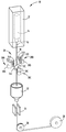
도 1은 제1실시예에 따른 인덱스 섭동 어셈블리를 포함하는 광섬유 제조 시스템을 나타내는 개략도이고;
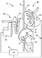
도 2는 도 1에 나타낸 광섬유 및 인덱스 섭동 어셈블리의 확대도이고;
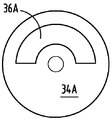
도 3a-3c는 다양한 실시예들에 따른 개방 윈도우를 갖춘 가스 초퍼 또는 셔터들의 개략도이고;
도 4는 동기화된 초퍼 제어 장치에 대한 섬유 위치의 함수로서 초퍼 개방/폐쇄 상태를 나타내는 타이밍도이고;
도 5는 비동기화된 초퍼 제어 장치에 대한 섬유 위치의 함수로서 초퍼 개방/폐쇄 상태를 나타내는 타이밍도이며;
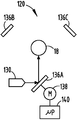
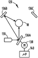
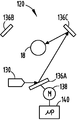
도 6a-6c는 제2실시예에 따른 섭동 소스로서 레이저 빔을 채용하는 인덱스 섭동 어셈블리를 나타낸다.1 is a schematic diagram showing an optical fiber manufacturing system including an index perturbation assembly according to a first embodiment;
FIG. 2 is an enlarged view of the optical fiber and index perturbation assembly shown in FIG. 1; FIG.
3A-3C are schematic views of gas choppers or shutters with open windows in accordance with various embodiments;
4 is a timing diagram showing the chopper open / closed state as a function of fiber position for a synchronized chopper control device;
5 is a timing diagram showing the chopper open / closed state as a function of fiber position for the unsynchronized chopper control device;
6A-6C show an index perturbation assembly employing a laser beam as a perturbation source according to a second embodiment.
이하 수반되는 도면을 참조하여 본 발명의 바람직한 실시예들에 대해 상세히 설명한다. 가능하다면, 도면 전체에 걸쳐 동일하거나 유사한 부분에 대해서는 동일한 도면참조부호가 사용될 것이다.Hereinafter, exemplary embodiments of the present invention will be described in detail with reference to the accompanying drawings. Wherever possible, the same reference numbers will be used for the same or similar parts throughout the drawings.
광섬유 제조 시스템 및 방법은 인발 공정의 사용을 통해 광섬유를 제조하고, 유리 레벨의 모드 결합을 도입하여 멀티모드 섬유(MMF)의 대역폭을 향상시키기 위해 상기 광섬유에 섭동을 도입한다.Fiber optic manufacturing systems and methods fabricate optical fibers through the use of drawing processes and introduce perturbation into the optical fibers to introduce glass-level mode coupling to improve the bandwidth of multimode fibers (MMF).
본원에서 그러한 광섬유 제조 시스템의 실시예들은 도 1-6c와 연관되어 기술되며, 그러한 도면 전체에 걸쳐 동일하거나 대응하는 요소들에는 유사한 참조부호가 표시된다. 본원에 사용된 표현 "베어 광섬유(bare optical fiber)"는 그 외면에 보호 코팅층을 제공하기 전(예컨대, 베어 광섬유가 폴리머계 재료로 코팅되기 전)에 모재로부터 직접 인발된 광섬유를 의미한다.Embodiments of such an optical fiber manufacturing system are described herein in connection with FIGS. 1-6C, wherein like or corresponding elements are denoted by like reference numerals throughout such figures. As used herein, the expression "bare optical fiber" refers to an optical fiber drawn directly from the base material before providing a protective coating layer on its outer surface (eg, before the bare fiber is coated with a polymeric material).
본원에 사용된 표현 "인덱스 섭동(index perturbation)"은 그러한 섬유에서의 굴절률의 로컬적 변동을 의미한다. 상기 광섬유 제조 시스템 및 방법은 광섬유 형성에 있어 특히 멀티모드 섬유에 대해 인덱스 섭동을 도입할 수 있게 하여, 본원에 기술된 바와 같이 섬유 길이를 따라 다양한 방위로 그와 같은 섭동을 분포시킬 수 있게 한다.As used herein, the expression "index perturbation" refers to the local variation in refractive index in such fibers. The optical fiber manufacturing system and method enables the introduction of index perturbation, particularly for multimode fibers, in the formation of optical fibers, allowing the distribution of such perturbations in various orientations along the fiber length as described herein.
도 1에 의하면, 통상 일 실시예에 따른 섬유 제조 방법에 의해 광섬유를 제조하기 위한 광섬유 제조 시스템(10)이 나타나 있다. 그러한 광섬유 제조 시스템(10)은 일 예에 따라 약 2000℃의 온도로 가열되는 노(12)를 포함한다. 통상 광섬유 모재(14)로 불리는 가열된 유리 소스는 상기 노(12) 내에 위치되며, 거기로부터 베어 광섬유(18)를 생성하기 위한 섬유가 인발된다. 상기 광섬유 모재(14)는 소정의 유리 또는 재료로 구성되며 광섬유의 제조를 위해 적절히 도핑된다. 일단 상기한 베어 광섬유(18)가 모재(14)로부터 인발되면, 상기 베어 광섬유(18)는 상기 노(12)의 출구(16)에 존재하는 그러한 베어 광섬유(18)가 원하는 온도 범위 내가 되도록 슬로우-냉각 장치(도시하지 않음)와 같은 공지의 기술 또는 다른 기술을 이용하여 원하는 온도로 냉각될 것이다. 상기 노(12)의 출구 오리피스(16; 즉 출구)에 존재하는 베어 광섬유(18)는 일정 인발 속도로 인발되는데, 그 베어 광섬유(18)가 냉각에 따라 부분적으로 응고되고 더 응고될 수 있는 용융 상태가 되는 섬유 직경 및 섬유 온도를 갖는다. 상기 베어 광섬유(18)가 상기 출구 오리피스(16)를 빠져나감에 따라 그 베어 광섬유(18)의 중심을 맞추기 위한 하나 또는 그 이상의 센터링 장치(centering device)가 채용될 수 있다는 것을 알아야 할 것이다.1, an optical
도 1에 나타낸 실시예에 있어서, 인덱스 섭동 어셈블리(20)는 출구 오리피스(16) 아래에 배치되며 상기 베어 광섬유(18)에 인덱스 섭동을 도입하도록 배열된다. 도 1에 나타낸 실시예에 있어서, 상기 인덱스 섭동 어셈블리(20)는 상기 베어 광섬유(18)의 외면에 제어된 인덱스 섭동을 도입하기 위해 각각 다른 각도로 각각 다른 방위각 위치에 배열된 다수의 섭동 소스를 포함한다. 이러한 실시예에 있어서, 그러한 섭동 소스는 다수의 제어가능 가스 블로잉 장치(30A~30C)를 포함하며, 그러한 각각의 가스 블로잉 장치는 상기 베어 광섬유(18)를 로컬적으로 냉각하기 위해 상기 베어 광섬유(18)의 외면 상에 가스를 블로우(blow)하도록 구성됨으로써 상기 외면에 인덱스 섭동을 야기한다. 상기 베어 광섬유(18; 이하 섬유 또는 광섬유)가 유리 전이 온도 정도의 온도 또는 그 유리 전이 온도와 가상 온도 사이의 온도를 갖는 그 베어 광섬유(18)의 위치(섬유가 노를 빠져 나가는 루트에 가까운 또는 그곳에서 가장 가까운)로 상기 가스가 블로우된다. 노(12)를 빠져 나가는 뜨거운 용융 섬유(18) 상에 공기와 같은 냉각 가스가 블로우됨으로써, 그러한 섬유(18)에서의 스트레스로 인해 본질적인 인덱스 프로파일 불균형 또는 섬유 복굴절이 야기된다. 그러한 인덱스 섭동은 상기 광섬유(18)의 축 길이를 따라 다양한 섬유 방위에 걸쳐 분포한다. 그러한 제어된 인덱스 섭동의 도입은 섬유 스피닝 또는 트위스팅의 필요성을 효과적으로 없애거나 감소시키는 한편 멀티모드 섬유의 대역폭을 향상시킨다. 각각 다른 방위로 그러한 인덱스 섭동을 분포시키기 위해, 몇몇 다른 방위각 위치들로부터 인덱스 섭동이 도입되며, 각각의 섭동 장치(30A-30C)는 상기 광섬유(18)의 축 길이(즉, 각각 다른 축 길이)를 따라 각각 다른 위치에 위치될 것이다. 본원에 개시된 방법은 그러한 인덱스 섭동이 원하는 높은 주파수 및 방위로 도입됨으로써 모드 결합이 좀더 효과적으로 이루어짐과 더불어 보다 짧은 길이 상황에서 대역폭 향상이 이루어진다. 이러한 인덱스 섭동 도입 방법을 이용할 경우, 섬유 스피닝이 제거되며, 또 어느 정도 감소된 섬유 스피닝은 다양한 실시예들에 따라 상기 방법과 연관되어 사용될 수 있다.In the embodiment shown in FIG. 1, the
그러한 인덱스 섭동을 도입하는 단계 다음은, 상기 베어 광섬유(18)가 코팅 유닛(22)을 거치는 것이며, 상기 코팅 유닛에서는 상기 베어 광섬유(18)의 외면에 1차 보호 코팅층이 제공된다. 다음에, 그렇게 코팅된 섬유는 그 코팅을 경화시키기 위해 자외선 램프를 갖춘 경화 유닛(24)을 통과한다.상기 경화 유닛(24)을 떠난 후, 보호층을 갖춘 광섬유(18)는 하나 또는 그 이상의 롤러(26) 및 트랙터(28; tractor)와 같은 상기 제조 시스템(10) 내의 다양한 처리 스테이지를 통과할 수 있다. 상기 트랙터(28)는 전체 섬유 제조 시스템을 통해 광섬유가 인발되어 최종 저장 스풀에 감김에 따라 그 광섬유(18)에 필요한 인장력을 제공하는데 사용될 것이다. 섬유(18)의 인발 속도가 제어되도록 상기 트랙터(28)가 제어된다는 것을 알 수 있을 것이다.Following the step of introducing such index perturbation, the bare
도 2에는, 도 1에 나타낸 제1실시예에 따른 인덱스 섭동 어셈블리(20)가 더 도시되어 있다. 이러한 실시예에 있어서, 상기 인덱스 섭동 어셈블리(20)는 상기 광섬유(18)의 외면 주위에 서로 공간적으로 떨어져 120°방위각으로 등각 배열된 가스 블로잉 장치(30A-30C)로 나타낸 3개의 인덱스 섭동 소스(인덱스 섭동 장치)를 포함한다. 그러한 나타낸 실시예에 있어서, 상기 가스 블로잉 장치(30A-30C)들은 각각 원하는 입사각으로 상기 광섬유(18)의 외면에 제어가능한 방식으로 가스를 블로우하기 위해 서로에 대해 상기 광섬유(18)의 축 길이를 따라 각각 다른 위치에 위치된다. 각각의 가스 블로잉 장치(30A 및 30B)는 광섬유(18)의 외면 상에 가스가 직접 향하도록 지향된 가스 블로잉 니들(32A-32C)을 포함한다. 상기 가스 블로잉 니들(32A-32C)은 일 실시예에 따라 가스 소스로부터 공급된 강제 냉각 가스 스트림을 연속으로 출력한다. 상기 가스는 질소, 헬륨, 산소 또는 가스 혼합물을 함유하는 공기를 포함한 소정의 적절한 냉각 가스를 포함할 것이다. 또한, 각각의 섭동 장치(30A-30C)는 하나 또는 그 이상의 개구(36A-36C)들로 규정된 개방 윈도우 패턴을 갖춘 디스크로서 나타낸 광학 초퍼 또는 셔터(34A-34C)를 포함한다. 각각의 광학 초퍼 또는 셔터(34A-34C)는 섬유(18)에 도달하도록 가스를 통과시키는 하나 또는 그 이상의 윈도우 개구 및 상기 섬유(18)에 대한 가스의 통과를 차단하는 고체 영역을 갖춘다. 상기 각각의 초퍼(34A-34C)는 광섬유(18)의 외면 상으로 가스 블로잉 니들(32A-32C)로부터 강제 도입된 가스를 제어하기 위해 대응하는 상기 가스 블로잉 니들(32A-32C)과 정렬된다. 상기 광학 초퍼 또는 셔터(34A-34C)는 대응하는 모터(38A-38C)들을 통해 회전되며, 상기 각각의 모터는 마이크로프로세서(40)로 나타낸 모터 제어 회로에 의해 제어된다. 따라서, 상기 초퍼 또는 셔터(34A-34C)는 상기 대응하는 가스 블로잉 니들(32A-32C)로부터 출력된 강제 가스 스트림을 중단하거나 셔터하도록 동작한다.FIG. 2 further shows an
상기 초퍼(34A-34C) 각각은 원하는 형태의 개방 윈도우를 가지며, 상기 모터(38A-38C)는 상기 광섬유(18)의 외면 상에 원하는 가스 주입을 달성하기 위해 상기 초퍼(34A-34C)의 회전을 제어한다. 상기 각각의 초퍼(34A-34C)는 대응하는 모터(38A-38C)에 의해 각 주파수(angle frequency) ω(radians/second) 또는 주파수 F(hertz)로 회전되며 한번의 완전한 회전 동안 제어된 시간 주기로 상기 섬유 상에 가스를 블로우하도록 실행된다. 일 실시예에 따르면, 상기 인덱스 섭동은 상기 광섬유(18)의 외측면 상에 통상 나선형 패턴으로 다수의 섭동 소스(30A-30C)에 의해 상기 광섬유의 축 길이를 따라 각각 다른 위치에 비동기적으로 도입된다. 그렇게 함으로써, 상기 모터(38A-38C)들은 제어된 위상으로 그리고 동기된 주파수로 동작한다. 주어진 공기 블로잉 니들(32A-32C)에 있어, 그러한 공기 블로잉 동작은 함수 

일 예에 따르면, 3개의 섭동 장치(30A-30C)에 있어서, 섬유에 대해, 제1섭동 장치(30A)는 0 m(meters)의 축 위치에 위치되고, 제2섭동 장치(30B)는 0.1 m의 축 위치에 위치되고, 제3섭동 장치(30C)는 0.2 m의 축 위치에 위치될 수 있다. 이러한 예에 있어서, 섬유 인발 속도는 초당 10 m로 설정될 것이다. 상기 광학 초퍼(34A-34C)들은 100 Hz와 같이 동일한 주파수로 회전될 것이다. 각 초퍼의 위상은 0, 


도 3a-3c는 각각의 가스 블로잉 장치(30A-30C)에 의해 채용되는 3개의 광학 초퍼 예를 나타낸다. 도 3a에 나타낸 광학 초퍼(34A)는 강제 가스 스트림을 1/2 회전 또는 1/2 시간 윈도우(36A)를 통해 유동시킬 수 있도록 180° 확장되는 개방 윈도우(36A)를 갖춘다. 도 3b에 나타낸 광학 초퍼(34A)는 강제 가스 스트림을 각 1/3 회전 또는 1/3 시간 윈도우(36A)를 통해 유동시킬 수 있도록 120° 확장되는 윈도우(36A)를 갖춘다. 도 3c에 나타낸 광학 초퍼(34A)는 각각 다른 주파수 성분들을 혼합할 수 있게 하는 2개의 윈도우(36A)들을 포함하는 복합 윈도우 배열을 갖는다. 각각의 초퍼(34A-34C) 내에 채용된 윈도우의 수는 초퍼 멀티플라이어(multiplier)로서 규정된다. 도 2에 나타낸 예에서, 초퍼 멀티플라이어에 의해, 0.03 m 또는 3 cm의 모드 결합 패턴의 공간 주기가 달성될 수 있다. 모터(38A-38C) 및 초퍼(34A-34C)의 성능은 원할 경우 1 mm 또는 그 이하의 공간 주기의 생성을 가능하게 한다. 다른 예에 따르면, 10의 등각으로 간격된 개방 윈도우(36A)들이 각 초퍼의 완전한 회전 주기 내에 채용됨으로써, 섬유(18) 상의 블로잉 패턴의 공간 주파수는 10의 인자로 멀티플라이 된다. 이런 식으로, 달성하기 어려운 공간 주파수가 달성될 수 있다.3A-3C show three optical chopper examples employed by each
다른 실시예에 따르면, 그러한 광섬유 제조 방법은 각각 다른 방위각 위치에 배열된 다수의 섭동 소스를 통해 광섬유로 인덱스 섭동을 도입할 수 있으며, 그러한 인덱스 섭동은 각각 다른 주파수로 다수의 섭동 소스에 의해 도입된다. 이러한 실시예에 있어서, 비동기 인덱스 섭동 도입 장치는 각각 다른 주파수들간 비팅(beating)이 높은 주파수의 섬유를 따라 분포된 섬유 스트레스의 불균형을 야기하는 각각 다른 시간에 초퍼(34A-34C)들의 개방을 허용하도록 각 모터에 대해 약간씩 다른 값들로 구동 모터 주파수를 설정함으로써 실시될 수 있다. 이는 마이크로프로세서(40)와 같은 제어 회로에 의해 달성되며, 상기 마이크로프로세서는 서로 다른 원하는 회전 속도를 달성하도록 각 개별 모터 주파수들을 제어한다. 일 예에 있어서, 초당 10 m의 인발 속도 및 각 초퍼에 대해 임의적으로 선택된 위상을 채용하는 동일한 초퍼 위치, 0 m, 0.1 m 및 0.2 m의 축 배치에서, 그러한 초퍼 주파수는 제1초퍼(34A)가 85 Hz의 주파수로 회전하고, 제2초퍼(34B)가 100 Hz의 주파수로 회전하며, 제3초퍼(34C)가 115 Hz의 주파수로 회전되도록 선택될 것이다. 이러한 예에 따른 초퍼 상태가 도 5에 나타나 있다. 어떠한 주어진 섬유 위치에서도, 하나 또는 그 이상의 초퍼는 개방 윈도우를 통해 냉각 가스를 광섬유(18)의 외면으로 블로우하도록 개방된다. 각 초퍼와 관련된 각각 다른 모터 속도에 따른 비팅으로 인해, 각각 다른 위치의 광섬유(18)는 멀티모드 섬유의 길이를 따라 모드 결합 생성을 돕는 아주 다른 주파수 성분들을 혼합하는 복합 패턴을 보인다.According to another embodiment, such optical fiber manufacturing methods may introduce index perturbations into optical fibers through multiple perturbation sources arranged at different azimuth locations, each of which is perturbed by multiple perturbation sources at different frequencies. . In this embodiment, the asynchronous index perturbation introducer allows opening of the
섭동 어셈블리(20)가 3개의 섭동 소스(30A-30C)를 채용하는 것으로 나타냈지만, 보다 많은 수의 인덱스 섭동 장치가 채용될 수 있다는 것을 알아야 한다. 일 실시예에 따르면, 그러한 인덱스 섭동 장치의 수는 3개 내지 20개의 범위에 있으며, 바람직하게 3-6개의 범위가 될 수 있다. 초퍼의 간격을 등각으로 나타냈지만, 그러한 간격은 일정하거나 일정하지 않을 수 있다는 것을 알아야 한다. 상기 섭동 장치(30A-30C)들의 축 위치 맞춤을 광섬유(18)의 길이에 따라 각각 다른 축 위치가 되는 것으로 나타냈지만, 상기 섭동 장치들은 상기 광섬유(18)의 동일한 축 위치 또는 길이로 채용될 수 있다는 것을 알아야 한다. 다수의 윈도우가 초퍼(34A-34C)에 채용될 경우, 그러한 윈도우는 등각으로 간격되거나 또는 등각으로 간격되지 않을 수 있다는 것을 알아야 한다. 다른 실시예에 있어서, 상기 모터들은 각각 다른 실시예들에 따라 초퍼(34A-34C)들이 균일한 속도를 갖지 않도록 조정될 수 있다. 초퍼(34)들은 또 다른 실시예들에 따라 공기를 블로우하도록 링 모터와 함께 상기 개방 윈도우로 교체될 수 있다. 또한, 상기 인덱스 섭동 도입 방법에 의해 섬유 스피닝이 제거되거나 감소될 지라도, 다양한 실시예들에 따라 섬유 스피닝이 광섬유 제조 방법과 연관되어 채용될 수 있다는 것을 알아야 한다.Although the
도 6a-6c에는, 제2실시예에 따른 인덱스 섭동 어셈블리(120)가 나타나 있다. 이러한 실시예에 있어서, 광섬유(18)를 따라 각각 다른 방위각 위치에 배열된 레이저 빔으로 이루어지는 다수의 섭동 소스를 통해 인덱스 섭동이 도입된다. 제1실시예에서 기술한 바와 같이 냉각 공기를 블로우함으로써 노에 존재하는 광섬유를 냉각하는 것과 반대로, 본 실시예는 인덱스 섭동을 야기하기 위해 선택 위치에서 광섬유(18)를 가열함으로써 인덱스 섭동을 야기한다. 이에 따라, 상기 레이저 빔은 상기 광섬유(18)에서의 스트레스가 인덱스 섭동을 야기하도록 상기 광섬유(18)의 온도 프로파일을 변경하기 위해 가열 소스로서 작용한다. 상기 인덱스 섭동 어셈블리(120)는 레이저 출력을 생성하기 위한 레이저 소스(130) 및 베어 광섬유(18)의 외면 상으로 그리고 각각 다른 방위각 위치로 레이저 출력 또는 빔을 지향시키기 위한 3개의 미러(136A-136C)를 채용한다. 미러(136A)는 마이크로프로세서(140)와 같은 제어 회로를 통해 제어된 모터(138)에 연결된 것으로 나타나 있다. 마이크로프로세서(140)로부터 제어 신호를 통해 작동된 모터(138)는 원하는 빔 방향을 달성하기 위해 빔 조향 미러(136)를 조향시킨다. 도 6a에 나타낸 바와 같이, 레이저 소스(130)에 의해 생성된 레이저 출력은 제1레이저 빔의 제1위치 또는 각도로 미러(136A)로부터 섬유(18) 상으로 반사된다. 다음에, 미러(136A)가 제2위치 또는 각도로 움직여, 도 6a에 나타낸 제1레이저 빔에 대해 120°로 나타낸 다른 제2각도로 광섬유(18)의 또 다른 표면 상으로 제2레이저 빔을 지향시키는 제2미러(136B) 상으로 상기 제1미러(136A)로부터의 레이저 출력을 지향시킨다. 도 6c에 있어서, 미러(136A)가 제3위치 또는 각도로 더 움직여, 도 6a에 나타낸 제1레이저 빔에 대해 240°로 나타낸 다른 제3각도로 광섬유(18)의 외면 상으로 제3레이저 빔을 지향시키는 제3미러(136C) 상으로 상기 레이저 출력을 재지향시킨다.6A-6C, an
본원에 나타냄과 더불어 기술한 바와 같이 레이저 빔들이 직접 광섬유(18) 상으로 반사되거나 또는 다른 방향으로 조향될 수 있다는 것을 알아야 한다. 또한, 본원에 기술된 미러 배열 대신 다수의 레이저 소스들이 채용될 수 있다는 것을 알아야 한다. 그러한 레이저 빔들은 본원에 기술된 다양한 실시예들에 따라 광섬유의 비동기 가열을 제공하도록 제어되거나 또는 각각 다른 주파수로 동작할 수 있다. 또한, 레이저 빔들은 축 길이를 따라 각각 다른 위치 또는 동일한 축 길이로 광섬유 상에 충돌될 수 있다는 것을 알아야 한다. 원하는 온도 프로파일을 얻기 위해, 레이저 조사 기간 및 방위 모두는 마이크로프로세서(140)에 의해 제어될 수 있다. 레이저 파워는 결과를 최적화하기 위해 변경될 수 있다. 그러한 레이저는 한정하진 않지만 10 ㎛ 정도에서 동작하는 CO2 레이저, 1 내지 2 ㎛에서 동작하는 YAG 레이저나 섬유 레이저, 또는 섬유 흡수 스펙트럼에 가까운 파장에서 동작하는 다른 레이저들을 포함하는 온도 프로파일을 변경하는데 사용될 수 있다. 가열 프로파일 및 강도 분포의 변경, 빔 균질기와 같은 추가 옵틱(optic) 및/또는 광학 렌즈가 사용될 수 있다. 상기 빔 균질기는 레이저 빔 강도 분포를 변경하며, 반면 상기 광학 렌즈는 섬유 상의 빔 크기를 변경한다. 그 모두는 독립적으로 또는 함께 조합되어 적용될 수 있다.It should be appreciated that the laser beams may be reflected directly onto the
그러한 레이저 가열 실시는 인발 속도에 따라 원하는 섭동 주파수로 펄스되는 2개 또는 그 이상의 개별 레이저 소스에 의해 달성될 수 있다. 그러한 펄스 레이저는 Q-스위치 레이저와 같이 매우 높은 파워를 갖는 1 kHz 주파수 이상의 주파수를 갖는 것으로 알려져 있으며, 또한 복합 섭동 패턴을 얻도록 동작에 있어 동기화될 수 있다. 매우 높은 주파수 섭동(frequency perturbation)의 실시는 옵틱을 이동시키기 위한 필요조건을 최소화할 수 있다.Such laser heating may be accomplished by two or more separate laser sources pulsed at the desired perturbation frequency depending on the drawing speed. Such pulsed lasers are known to have frequencies above 1 kHz with very high power, such as Q-switched lasers, and can also be synchronized in operation to obtain a complex perturbation pattern. Implementation of very high frequency perturbation can minimize the requirement for shifting optics.
따라서, 광섬유 제조 방법은 특히 멀티모드 섬유에 대해 유리 레벨의 모드 결합을 도입하기 위해 광섬유에 인덱스 섭동을 효과적으로 도입한다. 그러한 인덱스 섭동이 각각 다른 방위로 그리고 각각 다른 각도로부터 분포됨으로써 모드 결합이 좀더 효과적으로 이루어짐과 더불어 보다 짧은 길이 상황에서 대역폭 향상이 이루어진다.Thus, the optical fiber manufacturing method effectively introduces index perturbation into the optical fiber to introduce glass level mode coupling, especially for multimode fibers. Such index perturbations are distributed in different orientations and from different angles, resulting in more efficient mode combining and bandwidth improvements in shorter length situations.
본원 청구범위의 사상 및 범주를 벗어나지 않고 다양한 변동 및 변화가 이루어질 수 있다는 것은 당업자에게는 자명할 것이다.It will be apparent to those skilled in the art that various changes and modifications can be made without departing from the spirit and scope of the claims herein.
Claims (20)
광섬유에 대해 각각 다른 방위각 위치로 배열된 다수의 섭동 소스를 통해 상기 광섬유에 인덱스 섭동을 도입하는 단계를 포함하며,
상기 인덱스 섭동은 상기 광섬유에 스트레스를 야기하도록 각각 다른 주파수로 다수의 섭동 소스에 의해 도입되는 광섬유 제조 방법.Drawing the optical fiber from the heated glass source in the furnace; And
Introducing index perturbation into the optical fiber through a plurality of perturbation sources arranged at different azimuth positions with respect to the optical fiber,
And wherein the index perturbation is introduced by a plurality of perturbation sources at different frequencies to cause stress to the optical fiber.
상기 인덱스 섭동을 도입하는 단계 다음에 상기 광섬유를 코팅하는 단계를 더 포함하는 광섬유 제조 방법.The method according to claim 1,
Coating the optical fiber after introducing the index perturbation.
상기 인덱스 섭동은 광섬유의 축 길이를 따라 각각 다른 위치에 도입되는 광섬유 제조 방법.The method according to claim 1,
The index perturbation is introduced at different positions along the axis length of the optical fiber.
섭동 소스는 광섬유의 축 길이를 따라 각각 다른 위치에 배열되는 광섬유 제조 방법.The method of claim 3,
The perturbation source is arranged in different positions along the axis length of the optical fiber.
인덱스 섭동을 도입하는 단계는 인발된 광섬유의 외면 상에 다수의 가스 소스에 의해 가스를 블로우하는 단계를 포함하는 광섬유 제조 방법.The method according to claim 1,
Introducing index perturbation comprises blowing gas by a plurality of gas sources on the outer surface of the drawn optical fiber.
가스를 블로우하는 단계는 광섬유에 인가된 상기 가스 소스로부터 출력된 공기를 제어하는 대응하는 초퍼가 배열된 다수의 가스 소스에 의해 가스를 블로우하는 단계를 포함하는 광섬유 제조 방법.The method of claim 5,
Blowing gas includes blowing the gas by a plurality of gas sources arranged with corresponding choppers to control the air output from the gas source applied to the optical fiber.
상기 초퍼는 가스 소스에 따라 회전하며, 각각의 초퍼는 각각 다른 속도로 회전하는 광섬유 제조 방법.The method of claim 6,
Wherein the chopper rotates according to a gas source, and each chopper rotates at a different speed.
인덱스 섭동을 도입하는 단계는 인발된 광섬유를 다수의 레이저 출력에 의해 가열하는 단계를 포함하는 광섬유 제조 방법.The method according to claim 1,
Introducing index perturbation comprises heating the drawn optical fiber by a plurality of laser outputs.
인덱스 섭동을 도입하는 단계는 다수의 위치에 인덱스 섭동을 도입하는 단계를 포함하며, 상기 다수의 위치는 3 내지 20개의 위치 범위가 되는 광섬유 제조 방법.The method according to claim 1,
Introducing index perturbation includes introducing index perturbation at a plurality of locations, the plurality of locations being in a range of 3 to 20 locations.
광섬유는 멀티모드 섬유를 포함하는 광섬유 제조 방법.The method according to claim 1,
The optical fiber includes a multimode fiber.
광섬유에 대해 다수의 각각 다른 방위각 위치로 배열된 다수의 섭동 소스를 통해 상기 광섬유에 인덱스 섭동을 도입하는 단계를 포함하며,
상기 인덱스 섭동은 상기 광섬유에 스트레스를 야기하도록 광섬유의 외측면 상에 나선형 패턴으로 다수의 섭동 소스에 의해 광섬유의 축 길이를 따라 각각 다른 위치에 동기적으로 도입되는 광섬유 제조 방법.Drawing the optical fiber from the heated glass source in the furnace; And
Introducing index perturbation into the optical fiber through a plurality of perturbation sources arranged at a plurality of different azimuth positions relative to the optical fiber,
Wherein said index perturbation is introduced synchronously at different locations along the axis length of the optical fiber by a plurality of sources of perturbation in a spiral pattern on the outer surface of the optical fiber to cause stress to the optical fiber.
상기 인덱스 섭동을 도입하는 단계 다음에 상기 광섬유를 코팅하는 단계를 더 포함하는 광섬유 제조 방법.The method of claim 11,
Coating the optical fiber after introducing the index perturbation.
상기 다수의 섭동 소스는 광섬유의 축 길이를 따라 각각 다른 위치에 배열되는 광섬유 제조 방법.The method of claim 11,
Wherein the plurality of perturbation sources are arranged at different locations along the axial length of the optical fiber.
섭동 소스는 인덱스 섭동이 서로 동기적으로 도입되도록 원하는 위상을 제공하도록 제어되는 광섬유 제조 방법.The method of claim 11,
The perturbation source is controlled to provide a desired phase such that index perturbations are introduced synchronously with each other.
인덱스 섭동을 도입하는 단계는 인발된 광섬유의 외면 상에 다수의 가스 소스에 의해 가스를 블로우하는 단계를 포함하는 광섬유 제조 방법.The method of claim 11,
Introducing index perturbation comprises blowing gas by a plurality of gas sources on the outer surface of the drawn optical fiber.
상기 블로우 단계는 광섬유에 인가된 상기 가스 소스로부터 출력된 공기를 제어하는 대응하는 초퍼가 배열된 다수의 가스 소스에 의해 가스를 블로우하는 단계를 포함하는 광섬유 제조 방법.16. The method of claim 15,
And said blowing step comprises blowing the gas by a plurality of gas sources arranged with corresponding choppers for controlling the air output from the gas source applied to the optical fiber.
상기 초퍼는 가스 소스에 따라 회전하며, 각각의 초퍼는 인덱스 섭동의 동기화된 도입을 달성하기 위해 동일한 속도로 회전하는 광섬유 제조 방법.18. The method of claim 16,
The chopper rotates according to a gas source, each chopper rotating at the same speed to achieve a synchronized introduction of index perturbation.
인덱스 섭동을 도입하는 단계는 인발된 광섬유의 표면을 다수의 레이저 출력에 의해 가열하는 단계를 포함하는 광섬유 제조 방법.The method of claim 11,
Introducing index perturbation comprises heating the surface of the drawn optical fiber by a plurality of laser outputs.
인덱스 섭동을 도입하는 단계는 다수의 위치에 인덱스 섭동을 도입하는 단계를 포함하며, 상기 다수의 위치는 3 내지 20개의 위치 범위가 되는 광섬유 제조 방법.The method of claim 11,
Introducing index perturbation includes introducing index perturbation at a plurality of locations, the plurality of locations being in a range of 3 to 20 locations.
광섬유는 멀티모드 섬유를 포함하는 광섬유 제조 방법.The method of claim 11,
The optical fiber includes a multimode fiber.
Applications Claiming Priority (3)
| Application Number | Priority Date | Filing Date | Title |
|---|---|---|---|
| US201161526007P | 2011-08-22 | 2011-08-22 | |
| US61/526,007 | 2011-08-22 | ||
| PCT/US2012/051016 WO2013028439A1 (en) | 2011-08-22 | 2012-08-16 | Method for producing optical fiber having controlled index perturbations |
Publications (1)
| Publication Number | Publication Date |
|---|---|
| KR20140050102A true KR20140050102A (en) | 2014-04-28 |
Family
ID=46940571
Family Applications (1)
| Application Number | Title | Priority Date | Filing Date |
|---|---|---|---|
| KR1020147006780A Withdrawn KR20140050102A (en) | 2011-08-22 | 2012-08-16 | Method for producing optical fiber having controlled index perturbations |
Country Status (8)
| Country | Link |
|---|---|
| US (1) | US9290406B2 (en) |
| EP (1) | EP2748116B1 (en) |
| JP (1) | JP5993456B2 (en) |
| KR (1) | KR20140050102A (en) |
| CN (1) | CN103764580B (en) |
| BR (1) | BR112014004086A2 (en) |
| RU (1) | RU2014111036A (en) |
| WO (1) | WO2013028439A1 (en) |
Families Citing this family (4)
| Publication number | Priority date | Publication date | Assignee | Title |
|---|---|---|---|---|
| EP3419939A1 (en) * | 2016-02-24 | 2019-01-02 | Corning Incorporated | Methods and systems for processing optical fibers |
| WO2018063452A1 (en) * | 2016-09-29 | 2018-04-05 | Nlight, Inc. | Adjustable beam characteristics |
| WO2022072613A1 (en) | 2020-09-30 | 2022-04-07 | Corning Incorporated | Methods and systems for processing optical fiber |
| IL278789A (en) * | 2020-11-17 | 2022-06-01 | Teldor Cables & Systems Ltd | Distributed vibration sensing over optical fibers |
Family Cites Families (17)
| Publication number | Priority date | Publication date | Assignee | Title |
|---|---|---|---|---|
| US3912478A (en) | 1974-06-17 | 1975-10-14 | Bell Telephone Labor Inc | Methods of introducing geometrical variations in optical fibers |
| US4038062A (en) * | 1976-03-25 | 1977-07-26 | Bell Telephone Laboratories, Incorporated | Method and apparatus for introducing geometrical perturbations in optical fiber waveguides |
| GB8724892D0 (en) * | 1987-10-23 | 1987-11-25 | Gen Electric Co Plc | Optical fibres |
| CN1093842C (en) * | 1995-02-01 | 2002-11-06 | 等离子光纤维股份有限公司 | Optical Fiber with Small Polarization Mode Dispersion |
| WO1997007067A1 (en) | 1995-08-16 | 1997-02-27 | Plasma Optical Fibre B.V. | Optical fiber with low polarisation mode dispersion |
| US6422043B1 (en) | 1999-11-16 | 2002-07-23 | Fitel Usa Corp. | Method of making an improved multimode optical fiber and fiber made by method |
| JP2001287927A (en) * | 2000-04-04 | 2001-10-16 | Sumitomo Electric Ind Ltd | Optical fiber drawing method and apparatus |
| US6539154B1 (en) * | 2000-10-18 | 2003-03-25 | Corning Incorporated | Non-constant dispersion managed fiber |
| KR100417000B1 (en) * | 2001-12-03 | 2004-02-05 | 삼성전자주식회사 | Apparatus for low polarization mode dispersion |
| US6735985B2 (en) | 2001-12-20 | 2004-05-18 | Furukawa Electric North America Inc | Method of impressing a twist on a multimode fiber during drawing |
| NL1022315C2 (en) * | 2003-01-07 | 2004-07-13 | Draka Fibre Technology Bv | Method for manufacturing an optical fiber provided with variations in the refractive index. |
| US7861556B2 (en) * | 2003-02-28 | 2011-01-04 | Corning Incorporated | Method and apparatus for impulsively spinning optical fiber |
| US7536877B2 (en) * | 2003-04-04 | 2009-05-26 | Fitel Ush Corp. | Optical fiber fabrication and product |
| US7167621B2 (en) | 2004-11-03 | 2007-01-23 | Nufern | Optical fiber with suppressed stimulated Brillouin scattering and method for making such a fiber |
| WO2006058551A1 (en) * | 2004-12-02 | 2006-06-08 | Prysmian Cavi E Sistemi Energia S.R.L. | Method, system and device for imparting a predetermined rotation to an optical fibre |
| TWI326773B (en) | 2006-12-29 | 2010-07-01 | Ind Tech Res Inst | Improved optical fiber and the manufacturing method thereof |
| JP2011102964A (en) * | 2009-10-14 | 2011-05-26 | Sumitomo Electric Ind Ltd | Optical fiber and method of manufacturing optical fiber |
-
2012
- 2012-08-16 KR KR1020147006780A patent/KR20140050102A/en not_active Withdrawn
- 2012-08-16 RU RU2014111036/03A patent/RU2014111036A/en not_active Application Discontinuation
- 2012-08-16 BR BR112014004086A patent/BR112014004086A2/en not_active IP Right Cessation
- 2012-08-16 WO PCT/US2012/051016 patent/WO2013028439A1/en not_active Ceased
- 2012-08-16 EP EP12766491.0A patent/EP2748116B1/en not_active Not-in-force
- 2012-08-16 US US13/587,091 patent/US9290406B2/en not_active Expired - Fee Related
- 2012-08-16 JP JP2014527187A patent/JP5993456B2/en not_active Expired - Fee Related
- 2012-08-16 CN CN201280040864.5A patent/CN103764580B/en not_active Expired - Fee Related
Also Published As
| Publication number | Publication date |
|---|---|
| EP2748116A1 (en) | 2014-07-02 |
| JP2014529569A (en) | 2014-11-13 |
| WO2013028439A1 (en) | 2013-02-28 |
| CN103764580A (en) | 2014-04-30 |
| BR112014004086A2 (en) | 2017-02-21 |
| US20130047676A1 (en) | 2013-02-28 |
| US9290406B2 (en) | 2016-03-22 |
| JP5993456B2 (en) | 2016-09-14 |
| EP2748116B1 (en) | 2015-11-25 |
| CN103764580B (en) | 2016-10-05 |
| RU2014111036A (en) | 2015-09-27 |
Similar Documents
| Publication | Publication Date | Title |
|---|---|---|
| CN108025943B (en) | Method and apparatus for producing optical fibers with low fictive temperatures and optical fibers obtained therefrom | |
| RU2723407C2 (en) | Low-attenuation optical fiber | |
| US4038062A (en) | Method and apparatus for introducing geometrical perturbations in optical fiber waveguides | |
| KR20140050102A (en) | Method for producing optical fiber having controlled index perturbations | |
| KR100417000B1 (en) | Apparatus for low polarization mode dispersion | |
| JP4232910B2 (en) | Optical fiber manufacturing method with reduced polarization mode dispersion | |
| WO2019044703A1 (en) | Manufacturing method of optical fiber | |
| JP4482954B2 (en) | Optical fiber manufacturing method | |
| JP2019506359A (en) | Optical fiber processing method and system | |
| CN106338788A (en) | Method for efficiently fabricating Bragg grating on photonic crystal fiber | |
| JP3968061B2 (en) | Cooling device for ultra-high speed drawing | |
| JP2014227325A (en) | Production method of optical fiber | |
| US6884474B2 (en) | Method of coating a shaped body made of polymer material | |
| US5366530A (en) | Method and apparatus for fabricating an oval cross-sectional optical waveguide | |
| CN119143379B (en) | Optical system, optical fiber preparation device and optical fiber preparation method | |
| US8666213B2 (en) | Method of making multimode optical fibers | |
| KR100243325B1 (en) | Drawing apparatus and method for manufacturing optical fiber | |
| CN107056090A (en) | Fiber coat equipment and fiber coat method and fiber | |
| JP7610611B2 (en) | System and method for processing optical fiber - Patents.com | |
| US10486194B2 (en) | Post-draw tower optical fiber coating curing | |
| JP2005289729A (en) | Optical fiber manufacturing method | |
| JP2004239966A (en) | Optical fiber coupler, its manufacturing method and its manufacturing apparatus | |
| JPS62239111A (en) | Device for treating end face of plastic optical fiber | |
| KR20160078552A (en) | Coating apparatus for optical fiber | |
| KR20160078551A (en) | Coating apparatus for optical fiber |
Legal Events
| Date | Code | Title | Description |
|---|---|---|---|
| PA0105 | International application |
Patent event date: 20140313 Patent event code: PA01051R01D Comment text: International Patent Application |
|
| PG1501 | Laying open of application | ||
| PC1203 | Withdrawal of no request for examination | ||
| WITN | Application deemed withdrawn, e.g. because no request for examination was filed or no examination fee was paid |