KR20140051793A - 캔형 연소기용 버너 - Google Patents
캔형 연소기용 버너 Download PDFInfo
- Publication number
- KR20140051793A KR20140051793A KR1020130125805A KR20130125805A KR20140051793A KR 20140051793 A KR20140051793 A KR 20140051793A KR 1020130125805 A KR1020130125805 A KR 1020130125805A KR 20130125805 A KR20130125805 A KR 20130125805A KR 20140051793 A KR20140051793 A KR 20140051793A
- Authority
- KR
- South Korea
- Prior art keywords
- fuel
- streamlined
- flow
- burner
- trailing edge
- Prior art date
- Legal status (The legal status is an assumption and is not a legal conclusion. Google has not performed a legal analysis and makes no representation as to the accuracy of the status listed.)
- Granted
Links
Images




Classifications
-
- F—MECHANICAL ENGINEERING; LIGHTING; HEATING; WEAPONS; BLASTING
- F23—COMBUSTION APPARATUS; COMBUSTION PROCESSES
- F23R—GENERATING COMBUSTION PRODUCTS OF HIGH PRESSURE OR HIGH VELOCITY, e.g. GAS-TURBINE COMBUSTION CHAMBERS
- F23R3/00—Continuous combustion chambers using liquid or gaseous fuel
- F23R3/02—Continuous combustion chambers using liquid or gaseous fuel characterised by the air-flow or gas-flow configuration
- F23R3/16—Continuous combustion chambers using liquid or gaseous fuel characterised by the air-flow or gas-flow configuration with devices inside the flame tube or the combustion chamber to influence the air or gas flow
-
- F—MECHANICAL ENGINEERING; LIGHTING; HEATING; WEAPONS; BLASTING
- F23—COMBUSTION APPARATUS; COMBUSTION PROCESSES
- F23R—GENERATING COMBUSTION PRODUCTS OF HIGH PRESSURE OR HIGH VELOCITY, e.g. GAS-TURBINE COMBUSTION CHAMBERS
- F23R3/00—Continuous combustion chambers using liquid or gaseous fuel
- F23R3/02—Continuous combustion chambers using liquid or gaseous fuel characterised by the air-flow or gas-flow configuration
-
- F—MECHANICAL ENGINEERING; LIGHTING; HEATING; WEAPONS; BLASTING
- F02—COMBUSTION ENGINES; HOT-GAS OR COMBUSTION-PRODUCT ENGINE PLANTS
- F02C—GAS-TURBINE PLANTS; AIR INTAKES FOR JET-PROPULSION PLANTS; CONTROLLING FUEL SUPPLY IN AIR-BREATHING JET-PROPULSION PLANTS
- F02C9/00—Controlling gas-turbine plants; Controlling fuel supply in air- breathing jet-propulsion plants
- F02C9/26—Control of fuel supply
-
- F—MECHANICAL ENGINEERING; LIGHTING; HEATING; WEAPONS; BLASTING
- F02—COMBUSTION ENGINES; HOT-GAS OR COMBUSTION-PRODUCT ENGINE PLANTS
- F02C—GAS-TURBINE PLANTS; AIR INTAKES FOR JET-PROPULSION PLANTS; CONTROLLING FUEL SUPPLY IN AIR-BREATHING JET-PROPULSION PLANTS
- F02C9/00—Controlling gas-turbine plants; Controlling fuel supply in air- breathing jet-propulsion plants
- F02C9/26—Control of fuel supply
- F02C9/32—Control of fuel supply characterised by throttling of fuel
-
- F—MECHANICAL ENGINEERING; LIGHTING; HEATING; WEAPONS; BLASTING
- F02—COMBUSTION ENGINES; HOT-GAS OR COMBUSTION-PRODUCT ENGINE PLANTS
- F02C—GAS-TURBINE PLANTS; AIR INTAKES FOR JET-PROPULSION PLANTS; CONTROLLING FUEL SUPPLY IN AIR-BREATHING JET-PROPULSION PLANTS
- F02C9/00—Controlling gas-turbine plants; Controlling fuel supply in air- breathing jet-propulsion plants
- F02C9/26—Control of fuel supply
- F02C9/32—Control of fuel supply characterised by throttling of fuel
- F02C9/34—Joint control of separate flows to main and auxiliary burners
-
- F—MECHANICAL ENGINEERING; LIGHTING; HEATING; WEAPONS; BLASTING
- F23—COMBUSTION APPARATUS; COMBUSTION PROCESSES
- F23R—GENERATING COMBUSTION PRODUCTS OF HIGH PRESSURE OR HIGH VELOCITY, e.g. GAS-TURBINE COMBUSTION CHAMBERS
- F23R3/00—Continuous combustion chambers using liquid or gaseous fuel
- F23R3/02—Continuous combustion chambers using liquid or gaseous fuel characterised by the air-flow or gas-flow configuration
- F23R3/16—Continuous combustion chambers using liquid or gaseous fuel characterised by the air-flow or gas-flow configuration with devices inside the flame tube or the combustion chamber to influence the air or gas flow
- F23R3/18—Flame stabilising means, e.g. flame holders for after-burners of jet-propulsion plants
- F23R3/20—Flame stabilising means, e.g. flame holders for after-burners of jet-propulsion plants incorporating fuel injection means
-
- F—MECHANICAL ENGINEERING; LIGHTING; HEATING; WEAPONS; BLASTING
- F23—COMBUSTION APPARATUS; COMBUSTION PROCESSES
- F23R—GENERATING COMBUSTION PRODUCTS OF HIGH PRESSURE OR HIGH VELOCITY, e.g. GAS-TURBINE COMBUSTION CHAMBERS
- F23R3/00—Continuous combustion chambers using liquid or gaseous fuel
- F23R3/28—Continuous combustion chambers using liquid or gaseous fuel characterised by the fuel supply
-
- F—MECHANICAL ENGINEERING; LIGHTING; HEATING; WEAPONS; BLASTING
- F23—COMBUSTION APPARATUS; COMBUSTION PROCESSES
- F23R—GENERATING COMBUSTION PRODUCTS OF HIGH PRESSURE OR HIGH VELOCITY, e.g. GAS-TURBINE COMBUSTION CHAMBERS
- F23R3/00—Continuous combustion chambers using liquid or gaseous fuel
- F23R3/28—Continuous combustion chambers using liquid or gaseous fuel characterised by the fuel supply
- F23R3/286—Continuous combustion chambers using liquid or gaseous fuel characterised by the fuel supply having fuel-air premixing devices
-
- F—MECHANICAL ENGINEERING; LIGHTING; HEATING; WEAPONS; BLASTING
- F23—COMBUSTION APPARATUS; COMBUSTION PROCESSES
- F23R—GENERATING COMBUSTION PRODUCTS OF HIGH PRESSURE OR HIGH VELOCITY, e.g. GAS-TURBINE COMBUSTION CHAMBERS
- F23R3/00—Continuous combustion chambers using liquid or gaseous fuel
- F23R3/28—Continuous combustion chambers using liquid or gaseous fuel characterised by the fuel supply
- F23R3/34—Feeding into different combustion zones
-
- F—MECHANICAL ENGINEERING; LIGHTING; HEATING; WEAPONS; BLASTING
- F23—COMBUSTION APPARATUS; COMBUSTION PROCESSES
- F23R—GENERATING COMBUSTION PRODUCTS OF HIGH PRESSURE OR HIGH VELOCITY, e.g. GAS-TURBINE COMBUSTION CHAMBERS
- F23R3/00—Continuous combustion chambers using liquid or gaseous fuel
- F23R3/28—Continuous combustion chambers using liquid or gaseous fuel characterised by the fuel supply
- F23R3/34—Feeding into different combustion zones
- F23R3/346—Feeding into different combustion zones for staged combustion
-
- F—MECHANICAL ENGINEERING; LIGHTING; HEATING; WEAPONS; BLASTING
- F23—COMBUSTION APPARATUS; COMBUSTION PROCESSES
- F23R—GENERATING COMBUSTION PRODUCTS OF HIGH PRESSURE OR HIGH VELOCITY, e.g. GAS-TURBINE COMBUSTION CHAMBERS
- F23R3/00—Continuous combustion chambers using liquid or gaseous fuel
- F23R3/28—Continuous combustion chambers using liquid or gaseous fuel characterised by the fuel supply
- F23R3/36—Supply of different fuels
-
- F—MECHANICAL ENGINEERING; LIGHTING; HEATING; WEAPONS; BLASTING
- F23—COMBUSTION APPARATUS; COMBUSTION PROCESSES
- F23R—GENERATING COMBUSTION PRODUCTS OF HIGH PRESSURE OR HIGH VELOCITY, e.g. GAS-TURBINE COMBUSTION CHAMBERS
- F23R3/00—Continuous combustion chambers using liquid or gaseous fuel
- F23R3/42—Continuous combustion chambers using liquid or gaseous fuel characterised by the arrangement or form of the flame tubes or combustion chambers
- F23R3/46—Combustion chambers comprising an annular arrangement of several essentially tubular flame tubes within a common annular casing or within individual casings
-
- F—MECHANICAL ENGINEERING; LIGHTING; HEATING; WEAPONS; BLASTING
- F02—COMBUSTION ENGINES; HOT-GAS OR COMBUSTION-PRODUCT ENGINE PLANTS
- F02C—GAS-TURBINE PLANTS; AIR INTAKES FOR JET-PROPULSION PLANTS; CONTROLLING FUEL SUPPLY IN AIR-BREATHING JET-PROPULSION PLANTS
- F02C6/00—Plural gas-turbine plants; Combinations of gas-turbine plants with other apparatus; Adaptations of gas-turbine plants for special use
- F02C6/003—Gas-turbine plants with heaters between turbine stages
-
- F—MECHANICAL ENGINEERING; LIGHTING; HEATING; WEAPONS; BLASTING
- F05—INDEXING SCHEMES RELATING TO ENGINES OR PUMPS IN VARIOUS SUBCLASSES OF CLASSES F01-F04
- F05B—INDEXING SCHEME RELATING TO WIND, SPRING, WEIGHT, INERTIA OR LIKE MOTORS, TO MACHINES OR ENGINES FOR LIQUIDS COVERED BY SUBCLASSES F03B, F03D AND F03G
- F05B2260/00—Function
- F05B2260/20—Heat transfer, e.g. cooling
- F05B2260/221—Improvement of heat transfer
- F05B2260/222—Improvement of heat transfer by creating turbulence
-
- F—MECHANICAL ENGINEERING; LIGHTING; HEATING; WEAPONS; BLASTING
- F23—COMBUSTION APPARATUS; COMBUSTION PROCESSES
- F23R—GENERATING COMBUSTION PRODUCTS OF HIGH PRESSURE OR HIGH VELOCITY, e.g. GAS-TURBINE COMBUSTION CHAMBERS
- F23R2900/00—Special features of, or arrangements for continuous combustion chambers; Combustion processes therefor
- F23R2900/03341—Sequential combustion chambers or burners
Landscapes
- Engineering & Computer Science (AREA)
- Chemical & Material Sciences (AREA)
- Combustion & Propulsion (AREA)
- Mechanical Engineering (AREA)
- General Engineering & Computer Science (AREA)
- Gas Burners (AREA)
- Nozzles For Spraying Of Liquid Fuel (AREA)
Abstract
Description
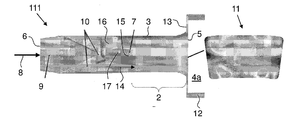
도 1은 개별 혼합 및 분사 구성 요소를 갖는 공지된 SEV 버너를 도시하는 도면.
도 2는 버너의 출구에서 연료량 부분 윤곽(우측)과 함께 고압 터빈의 하류에 위치하는 공지된 SEV 버너를 도시하는 도면.
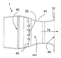
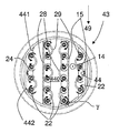
도 3은 본 발명에 따른 원형 제한 벽을 갖는 혼합 및 분사 장치 및 원통형 연소실을 갖는 SEV 버너를 도시하는 도면.
도 4는 도 3에 따른 혼합 및 분사 장치를 도시하는 도면.
도 5는 로빙 플루트를 도시하는 도면으로서, a)는 길이 방향 축에 수직인 절취도, b)는 측면도, c)는 후미 에지 상의, 주 유동에 대한 도면, d)는 사시도.
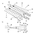
도 6에서, a)는 로빙된 유선형 몸체 및 양 측면들 상에 생성된 유동 통로와 후미 에지에 대한 개략 사시도, b)는 그의 측면 입면도.
도 7은 도 3에 따른 버너의 복수의 몸체들에 대한 a)는 정면도, b)는 사시도이고, 여기서 상기 몸체들은 로빙되지 않으나 와류 발생기들을 구비하며, c)는 상기 와류 발생기의 어택 각도와 스윕 각도가 어떻게 규정되는지를 설명하는 모식도로서, 상부 도면에는 측면 입면도가 도시되고, 하부 도면에는 와류 발생기가 장착되는 평면과 수직인 방향으로의 와류 발생기 상의 도면이 도시된다.
도 8은 상이한 노즐과 로브 장치들을 갖는 로빙 플루트의 후미 에지를 도시하는 도면.
도 9는, 유동 교정기로서 작용하는, 도 3에 따른 혼합 분사 장치를 도시한 도면.
2: 혼합 공간, 혼합 구역
3: 버너 벽
4a: 연소 공간
4b: 재순환 공간
5: 출구측, 버너 출구
6: 입구측
7: 분사 장치, 연료 랜스
8: 고압 터빈으로부터의 유동
9: 터빈 출구 안내 베인들
10: 일차 와류 발생기
11: 5에서 연료량 부분 윤곽
12: 연소실 벽
13: 3과 12 사이의 전이부
14: 산화 매질의 유동
15: 연료 노즐
16: 7의 풋
17: 7의 샤프트
22: 유선형 몸체, 플루트
24: 22의 후미 에지
25: 22의 선단 에지
27: 전환점
28: 제 2 가로 방향(30)에서의 로브
29: 제 3 가로 방향(31)에서의 로브
30: 제 2 가로 방향
31: 제 3 가로 방향
32: 28, 29의 정점
33: 22의 측면
34: 분출 방향
35: 22의 중앙면
38: 24의 선단 에지
39: 23의 후미 에지
40: 유동 프로파일
41: 와류
42: 로브들
43: 혼합 및 분사 장치
44: 제한 벽
440: 가스-유동 채널
441: 44의 제 1 영역
442: 44의 제 2 영역
45: 입구 영역
46: 출구 영역
47: 440의 길이 방향 축
48: 유선형 프로파일
49: 제 1 가로 방향
50: 입구 유동
51: 제 1 노즐
52: 제 2 노즐
53: 제 3 노즐
54: 슬롯 노즐
60: 와류 발생기
111: 공지된 버너
λ: 42의 주기성
h1: 42의 높이
h2: 60의 높이
α1: 제 1 로브 각도
α2: 제 2 로브 각도
β: 입구 각도
γ: 진입 각도
l: 22의 길이
H: 22의 높이
t1: 체류 시간
t2: 점화 시간
t3: 반응 시간
w: 후미 에지(24)에서의 폭
W: 22의 최대 폭
Claims (15)
- 혼합 및 분사 장치(43)를 구비한 가스 터빈의 연소실용 버너(1)로서, 상기 혼합 및 분사 장치(43)는:
길이 방향 축(47)을 갖는 가스-유동 채널(440), 입구 영역(45), 및 주-유동 방향(14)으로 입구 영역의 하류에 위치한 출구 영역(46)을 구성하는 제한 벽(44); 및
적어도 2개의 유선형 몸체들(22)로서, 상기 주-유동 방향(14)에 대해 수직 또는 경사진 상기 제한 벽(44)의 제 1 영역(441)으로부터 상기 가스-유동 채널(440) 내로 제 1 가로 방향(49)으로 각각 연장하는, 상기 적어도 2개의 유선형 몸체들을 포함하며,
각각의 유선형 몸체들(22)은 상기 주-유동 방향(14)과 대체로 평행하게 배열되고 중간에 중앙면(35)을 갖는 2개의 측면들(33)을 가지며, 상기 측면들(33)은 상기 몸체(22)의 선단 에지(25)를 형성하기 위해 상류측에서 서로 결합되고 또한 상기 몸체(22)의 후미 에지(24)를 형성하기 위해 하류측에서 결합되고,
각각의 유선형 몸체(22)는 유선형 프로파일(48)로서 성형되는 상기 제 1 가로 방향(49)과 수직인 단면을 가지며,
상기 유선형 몸체들(22) 중 적어도 하나에는 혼합 구조체(28, 29; 60), 및 상기 유동 채널(440) 내로 상기 주-유동 방향(14)과 대체로 평행하게 적어도 하나의 연료를 도입시키기 위해 그의 후미 에지(24)에 위치되는 적어도 하나의 연료 노즐(15)이 구비되는, 상기 가스 터빈의 연소실용 버너(1)에 있어서,
상기 유선형 몸체들(22) 중 적어도 2개는 상기 제 1 가로 방향(49)을 따라 상이한 길이들을 갖는 것을 특징으로 하는 가스 터빈의 연소실용 버너(1). - 제 1 항에 있어서, 상기 가스-유동 채널(440)의 단면은 대체로 볼록하게 굴곡되고, 상기 가스-유동 채널(440)의 단면은 적합하게는 볼록 거리 공간(metric space), 더욱 적합하게는 대체로 원형, 타원형 또는 렌즈 형상(lensoid shape)인 것을 특징으로 하는 가스 터빈의 연소실용 버너(1).
- 제 1 항 또는 제 2 항에 있어서, 상기 유선형 몸체들(22) 중 적어도 하나에는 상기 몸체(22)의 후미 에지(24)에 위치된 복수의 로브들(lobes;28, 29) 형태로 상기 혼합 구조체가 제공되며, 상기 로브들(28, 29)은 제 2 가로 방향(30) 또는 제 3 가로 방향(31)으로 상기 중앙면(35)과 대체로 수직으로 연장하며, 상기 제 2 및 제 3 가로 방향들(30, 31)은 서로 반대로 움직이며, 선단 에지 영역으로부터 상기 로브들(28, 29)로 하류 방향으로의 전이부는 연속 1차 도함수를 갖는 함수를 나타내는 표면 곡률(surface curvature)로서 평탄하며, 적합하게도, 상기 로브들(28, 29)을 형성하는 상기 유선형 몸체(22)의 가로 변위는 상기 몸체(22) 길이(1)의 최대 2/3만큼 하류에, 더욱 적합하게는 상기 몸체(22)의 길이(1)의 1/2만큼 하류에 있는 것을 특징으로 하는 가스 터빈의 연소실용 버너(1).
- 제 1 항 내지 제 3 항 중 어느 한 항에 있어서, 상기 로빙(lobing) 후미 에지(24)에는 그의 전체 길이에 걸쳐 로브들(28, 29)이 제공되며, 상기 로브들(28, 29)은 하나가 상기 후미 에지(24)를 따라 다음에 인접하는 방식으로 연속 배열되며 또한 2개의 대향하는 제 2 및 제 3 가로 방향들(30, 31)에서 20 밀리미터 내지 100 밀리미터, 적합하게는 30 밀리미터 내지 60 밀리미터 범위의 적절한 로브 파장(λ)으로 교대로 로빙되며, 적합하게도, 모든 유선형 몸체들(22)에는 하나의 동일한 로브 파장(λ)이 제공되는 것을 특징으로 하는 가스 터빈의 연소실용 버너(1).
- 제 1 항 내지 제 4 항 중 어느 한 항에 있어서, 상기 유선형 프로파일(48)은 제 2 및 제 3 가로 방향(30, 31)으로 폭(w)을 갖고, 상기 몸체(22)의 상기 후미 에지(24)보다도 상기 선단 에지(25)에 근접해서 최대 폭(W)을 가지며, 상기 폭(w)은 근본적으로 상기 후미 에지(24)를 향해 연속적으로 줄어들며, 상기 동일한 몸체(22)의 인접한 로브들(28, 29)의 정점들(32) 사이의 상기 중앙면(35)과 수직인 거리로서 규정된 로브 높이(h1)는 5 밀리미터 내지 60 밀리미터의 범위를 갖는 것을 특징으로 하는 가스 터빈의 연소실용 버너(1).
- 제 1 항 내지 제 5 항 중 어느 한 항에 있어서, 상기 로브 높이(h1) 대 상기 가스-유동 채널(440)의 최소 직경의 비율은 1:4 내지 1:20, 적합하게는 1:5 내지 1:10의 범위를 갖는 것을 특징으로 하는 가스 터빈의 연소실용 버너(1).
- 제 1 항 내지 제 6 항 중 어느 한 항에 있어서, 상기 로빙 후미 에지(24)는 70도 내지 110도, 적합하게는 80도 내지 100도의 범위를 갖는, 특히 90도의 진입 각도(γ)로 상기 제한 벽(44)과 만나는 것을 특징으로 하는 가스 터빈의 연소실용 버너(1).
- 제 1 항 내지 제 7 항 중 어느 한 항에 있어서, 상기 유선형 몸체들(22) 중 적어도 하나에는, 상기 선단 에지(25)와 상기 후미 에지(24) 사이에서, 그의 측면들(33) 중 적어도 하나에 위치한 적어도 2개의 와류 발생기들(60) 형태의 혼합 구조체가 제공되며, 상기 와류 발생기들은 각각 상기 중앙면(35)과 대체로 수직으로 연장하는 와류 발생기 높이(h2)를 갖는 것을 특징으로 하는 가스 터빈의 연소실용 버너(1).
- 제 8 항에 있어서, 상기 와류 발생기 높이(h2)는 10 밀리미터 내지 50 밀리미터의 범위를 가지며, 적합하게도, 상기 와류 발생기(60)는 연료 노즐들(15)과 교대로 상기 2개의 측면들(33)에 위치되거나, 또는 각각의 와류 발생기(60) 하류에는 상기 연료 노즐들(15) 중 적어도 2개가 위치되어 있는 것을 특징으로 하는 가스 터빈의 연소실용 버너(1).
- 제 8 항 또는 제 9 항에 있어서, 상기 와류 발생기(60)로부터 상기 제한 벽(44)까지의 또는 다른 유선형 몸체(22)의 와류 발생기까지의 최소 횡단 거리는 상기 와류 발생기 높이(h2)의 20% 내지 40%의 범위를 갖는 것을 특징으로 하는 가스 터빈의 연소실용 버너(1).
- 제 1 항 내지 제 10 항 중 어느 한 항에 있어서, 상기 유선형 몸체들(22)은 상기 제한 벽(44)의 제 1 영역(441)으로부터 상기 가스-유동 채널(440)을 통해 상기 제한 벽(44)의 제 2 영역(442)으로 연장하며, 적어도 하나의 유선형 몸체(22)의 길이 방향(49)은 근본적으로 직선이며 또한 상기 제한 벽(44)의 상기 제 1 영역(441) 및/또는 상기 제 2 영역과의 접평면(tangent plane)은 서로에 대해 경사지는 것을 특징으로 하는 가스 터빈의 연소실용 버너(1).
- 제 3 항 내지 제 11 항 중 어느 한 항에 있어서, 상기 유선형 몸체들(22)은 근본적으로 서로 평행한 길이 방향들(49)로 배열되며, 최근접 이웃하는 유선형 몸체들(22)의 로브들(28, 29)은, 존재할 경우, 동-위상(in-phase) 또는 이-위상(out-of-phase)으로 로빙되는 것을 특징으로 하는 가스 터빈의 연소실용 버너(1).
- 제 1 항 내지 제 12 항 중 어느 한 항에 있어서, 상기 혼합 및 분사 장치(43)는 프로파일을 갖는 각각의 유선형 몸체(22)의 상기 선단 에지(25)에 제공됨으로써 유동 교정기(flow straightener)로서 작용하며, 상기 선단 에지 위치에서 우세한 상기 주-유동 방향(14)과 평행하게 지향되는 것을 특징으로 하는 가스 터빈의 연소실용 버너(1).
- 제 1 항 내지 제 13 항 중 어느 한 항에 따른 버너(1)의 작동 방법으로서, 연료가 분사되는 연료 분사 노즐들의 수는 상기 전체 분사된 연료 유동의 함수로서 결정되며, 적합하게도, 한계값 연료 유동 밑에서, 연료는 유선형 몸체(22)의 모든 제 2 연료 노즐(15)을 통해서만 분사되고 그리고/또는 연료는 상기 버너(1)의 모든 제 2 또는 제 3 유선형 몸체(22)의 연료 노즐들을 통해서만 분사되는 것을 특징으로 하는 버너(1)의 작동 방법.
- 높은 반응 조건들 하에서 연소시키기 위한, 적합하게는 높은 버너 입구 온도들에서의 연소를 위한 및/또는 MBtu 연료의 연소를 위한 및/또는 수소 농후 연료의 연소를 위한, 제 1 항 내지 제 13 항 중 어느 한 항에 따른 버너(1)의 사용.
Applications Claiming Priority (2)
| Application Number | Priority Date | Filing Date | Title |
|---|---|---|---|
| EP12189606 | 2012-10-23 | ||
| EP12189606.2 | 2012-10-23 |
Publications (2)
| Publication Number | Publication Date |
|---|---|
| KR20140051793A true KR20140051793A (ko) | 2014-05-02 |
| KR101619201B1 KR101619201B1 (ko) | 2016-05-10 |
Family
ID=47073332
Family Applications (1)
| Application Number | Title | Priority Date | Filing Date |
|---|---|---|---|
| KR1020130125805A Expired - Fee Related KR101619201B1 (ko) | 2012-10-23 | 2013-10-22 | 캔형 연소기용 버너 |
Country Status (6)
| Country | Link |
|---|---|
| US (3) | US10267522B2 (ko) |
| EP (3) | EP3184899B1 (ko) |
| JP (1) | JP5871881B2 (ko) |
| KR (1) | KR101619201B1 (ko) |
| CN (1) | CN103776059B (ko) |
| CA (1) | CA2830031C (ko) |
Families Citing this family (39)
| Publication number | Priority date | Publication date | Assignee | Title |
|---|---|---|---|---|
| RU2550370C2 (ru) * | 2011-05-11 | 2015-05-10 | Альстом Текнолоджи Лтд | Центробежная форсунка с выступающими частями |
| EP2837883B1 (en) * | 2013-08-16 | 2018-04-04 | Ansaldo Energia Switzerland AG | Premixed can annular combustor with mixing lobes for the second stage of a sequential gas turbine |
| EP3023696B1 (en) * | 2014-11-20 | 2019-08-28 | Ansaldo Energia Switzerland AG | Lobe lance for a gas turbine combustor |
| EP3029378B1 (en) | 2014-12-04 | 2019-08-28 | Ansaldo Energia Switzerland AG | Sequential burner for an axial gas turbine |
| EP3056819B1 (en) * | 2015-02-11 | 2020-04-01 | Ansaldo Energia Switzerland AG | Fuel injection device for a gas turbine |
| US10151325B2 (en) * | 2015-04-08 | 2018-12-11 | General Electric Company | Gas turbine diffuser strut including a trailing edge flap and methods of assembling the same |
| EP3115693B1 (en) | 2015-07-10 | 2021-09-01 | Ansaldo Energia Switzerland AG | Sequential combustor and method for operating the same |
| EP3147569A1 (en) | 2015-09-28 | 2017-03-29 | General Electric Technology GmbH | Vortex generator, and fuel injection system of a gas turbine with such vortex generator |
| RU2717472C2 (ru) * | 2016-08-16 | 2020-03-23 | Ансальдо Энергия Свитзерленд Аг | Инжекторное устройство и способ изготовления инжекторного устройства |
| EP3306197B1 (en) | 2016-10-08 | 2020-01-29 | Ansaldo Energia Switzerland AG | Dual fuel injector for a sequential burner of a sequential gas turbine |
| EP3324120B1 (en) * | 2016-11-18 | 2019-09-18 | Ansaldo Energia Switzerland AG | Additively manufactured gas turbine fuel injector device |
| EP3330614B1 (en) * | 2016-11-30 | 2019-10-02 | Ansaldo Energia Switzerland AG | Vortex generating device |
| EP3330613B1 (en) | 2016-11-30 | 2020-10-21 | Ansaldo Energia Switzerland AG | Vortex generating device |
| EP3354984B1 (en) * | 2017-01-31 | 2020-09-09 | Ansaldo Energia Switzerland AG | Lobed injector for a gas turbine combustor |
| EP3369995B1 (en) | 2017-03-02 | 2020-08-05 | Ansaldo Energia Switzerland AG | Method of flow oscillation cancellation in a mixer |
| US10969107B2 (en) | 2017-09-15 | 2021-04-06 | General Electric Company | Turbine engine assembly including a rotating detonation combustor |
| RU2747655C2 (ru) * | 2017-11-17 | 2021-05-11 | Ансальдо Энергия Свитзерленд Аг | Горелка промежуточного подогрева для газовой турбины и газовая турбина, содержащая такую горелку промежуточного подогрева |
| US11242806B2 (en) * | 2017-11-20 | 2022-02-08 | Power Systems Mfg., Llc | Method of controlling fuel injection in a reheat combustor for a combustor unit of a gas turbine |
| CN111121042B (zh) * | 2018-10-31 | 2025-02-18 | 宁波方太厨具有限公司 | 一种用于燃气灶的引射管 |
| US11156164B2 (en) | 2019-05-21 | 2021-10-26 | General Electric Company | System and method for high frequency accoustic dampers with caps |
| US11174792B2 (en) | 2019-05-21 | 2021-11-16 | General Electric Company | System and method for high frequency acoustic dampers with baffles |
| IT201900007440A1 (it) * | 2019-05-28 | 2020-11-28 | Sabaf Spa | Bruciatore a gas |
| GB201907834D0 (en) * | 2019-06-03 | 2019-07-17 | Rolls Royce Plc | A fuel sparay nozzle arrangement |
| CN110822482B (zh) * | 2019-11-28 | 2020-10-27 | 中国航发沈阳黎明航空发动机有限责任公司 | 一种中低热值气体和液体双燃料喷嘴及燃料切换方法 |
| JP2024540427A (ja) | 2021-11-03 | 2024-10-31 | パワー システムズ エムエフジー,リミティド ライアビリティ カンパニー | 保炎緩和のための後縁燃料噴射強化 |
| CN115075951A (zh) * | 2022-06-02 | 2022-09-20 | 中国联合重型燃气轮机技术有限公司 | 二次燃烧装置和具有其的燃烧室和燃气轮机 |
| JP2024061123A (ja) * | 2022-10-21 | 2024-05-07 | 三菱重工業株式会社 | バーナ、これを備える燃焼器、及びこの燃焼器を備えるガスタービン |
| CN115899686B (zh) * | 2022-11-19 | 2026-04-10 | 宁波方太厨具有限公司 | 一种燃烧器引射组件及应用有该引射组件的燃气灶具 |
| US12442331B2 (en) | 2023-02-02 | 2025-10-14 | Pratt & Whitney Canada Corp. | High shear fuel distributor |
| US12111056B2 (en) | 2023-02-02 | 2024-10-08 | Pratt & Whitney Canada Corp. | Combustor with central fuel injection and downstream air mixing |
| US12607357B2 (en) | 2023-02-02 | 2026-04-21 | Pratt & Whitney Canada Corp. | Combustor with fuel plenum and extending mixing passages |
| US12259135B2 (en) | 2023-02-02 | 2025-03-25 | Pratt & Whitney Canada Corp. | Combustor with fuel and air mixing plenum |
| US12339005B2 (en) | 2023-02-02 | 2025-06-24 | Rtx Corporation | Hydrogen fuel distributor |
| US11873993B1 (en) | 2023-02-02 | 2024-01-16 | Pratt & Whitney Canada Corp. | Combustor for gas turbine engine with central fuel injection ports |
| US11867400B1 (en) | 2023-02-02 | 2024-01-09 | Pratt & Whitney Canada Corp. | Combustor with fuel plenum with mixing passages having baffles |
| US11867392B1 (en) | 2023-02-02 | 2024-01-09 | Pratt & Whitney Canada Corp. | Combustor with tangential fuel and air flow |
| US11835235B1 (en) | 2023-02-02 | 2023-12-05 | Pratt & Whitney Canada Corp. | Combustor with helix air and fuel mixing passage |
| US12060997B1 (en) | 2023-02-02 | 2024-08-13 | Pratt & Whitney Canada Corp. | Combustor with distributed air and fuel mixing |
| CN119665272B (zh) * | 2024-11-20 | 2025-12-26 | 北京航空航天大学 | 一种液体碳氢燃料与氢燃料的双燃料燃烧喷嘴 |
Family Cites Families (20)
| Publication number | Priority date | Publication date | Assignee | Title |
|---|---|---|---|---|
| GB595286A (ko) * | 1942-01-08 | 1947-12-01 | ||
| CA1324999C (en) * | 1986-04-30 | 1993-12-07 | Walter M. Presz, Jr. | Bodies with reduced surface drag |
| CH674561A5 (ko) | 1987-12-21 | 1990-06-15 | Bbc Brown Boveri & Cie | |
| US5203796A (en) * | 1990-08-28 | 1993-04-20 | General Electric Company | Two stage v-gutter fuel injection mixer |
| US5010453A (en) * | 1990-08-28 | 1991-04-23 | General Motors Corporation | Vehicle lamp ventilation system |
| EP0577862B1 (de) | 1992-07-03 | 1997-03-12 | Abb Research Ltd. | Nachbrenner |
| DE4426351B4 (de) | 1994-07-25 | 2006-04-06 | Alstom | Brennkammer für eine Gasturbine |
| DE19549143A1 (de) * | 1995-12-29 | 1997-07-03 | Abb Research Ltd | Gasturbinenringbrennkammer |
| FR2745605B1 (fr) * | 1996-03-01 | 1998-04-30 | Aerospatiale | Dispositif d'injection de combustible pour statoreacteur d'aeronef |
| EP0918191B1 (de) * | 1997-11-21 | 2003-07-02 | Alstom | Brenner für den Betrieb eines Wärmeerzeugers |
| DE10008006C2 (de) | 2000-02-22 | 2003-10-16 | Graffinity Pharm Design Gmbh | SPR-Sensor und SPR-Sensoranordnung |
| DE10128063A1 (de) | 2001-06-09 | 2003-01-23 | Alstom Switzerland Ltd | Brennersystem |
| DE10312971B4 (de) | 2003-03-24 | 2017-04-06 | General Electric Technology Gmbh | Verfahren zum Betreiben einer Gasturbogruppe |
| US8763400B2 (en) * | 2009-08-04 | 2014-07-01 | General Electric Company | Aerodynamic pylon fuel injector system for combustors |
| EP2496883B1 (en) * | 2009-11-07 | 2016-08-10 | Alstom Technology Ltd | Premixed burner for a gas turbine combustor |
| WO2011054760A1 (en) | 2009-11-07 | 2011-05-12 | Alstom Technology Ltd | A cooling scheme for an increased gas turbine efficiency |
| WO2011054757A2 (en) * | 2009-11-07 | 2011-05-12 | Alstom Technology Ltd | Reheat burner injection system with fuel lances |
| WO2011054766A2 (en) | 2009-11-07 | 2011-05-12 | Alstom Technology Ltd | Reheat burner injection system |
| CH704829A2 (de) * | 2011-04-08 | 2012-11-15 | Alstom Technology Ltd | Gasturbogruppe und zugehöriges Betriebsverfahren. |
| EP2522912B1 (en) * | 2011-05-11 | 2019-03-27 | Ansaldo Energia Switzerland AG | Flow straightener and mixer |
-
2013
- 2013-10-11 CA CA2830031A patent/CA2830031C/en active Active
- 2013-10-15 EP EP16207652.5A patent/EP3184899B1/en active Active
- 2013-10-15 EP EP13188698.8A patent/EP2725301B1/en active Active
- 2013-10-15 EP EP16207654.1A patent/EP3182013B1/en active Active
- 2013-10-22 KR KR1020130125805A patent/KR101619201B1/ko not_active Expired - Fee Related
- 2013-10-22 JP JP2013219566A patent/JP5871881B2/ja not_active Expired - Fee Related
- 2013-10-23 US US14/060,931 patent/US10267522B2/en active Active
- 2013-10-23 CN CN201310500719.7A patent/CN103776059B/zh active Active
-
2017
- 2017-03-01 US US15/446,407 patent/US10544939B2/en active Active
- 2017-03-01 US US15/446,451 patent/US10386073B2/en active Active
Also Published As
| Publication number | Publication date |
|---|---|
| CN103776059A (zh) | 2014-05-07 |
| US10386073B2 (en) | 2019-08-20 |
| EP3184899B1 (en) | 2020-05-20 |
| EP3182013B1 (en) | 2021-02-17 |
| EP2725301B1 (en) | 2018-12-05 |
| JP2014085106A (ja) | 2014-05-12 |
| CA2830031C (en) | 2016-03-15 |
| EP3184899A8 (en) | 2017-12-13 |
| US20140109588A1 (en) | 2014-04-24 |
| CA2830031A1 (en) | 2014-04-23 |
| CN103776059B (zh) | 2016-04-13 |
| US10267522B2 (en) | 2019-04-23 |
| US20170191665A1 (en) | 2017-07-06 |
| US20170234541A1 (en) | 2017-08-17 |
| EP3182013A1 (en) | 2017-06-21 |
| US10544939B2 (en) | 2020-01-28 |
| KR101619201B1 (ko) | 2016-05-10 |
| EP2725301A1 (en) | 2014-04-30 |
| JP5871881B2 (ja) | 2016-03-01 |
| EP3184899A1 (en) | 2017-06-28 |
Similar Documents
| Publication | Publication Date | Title |
|---|---|---|
| KR101619201B1 (ko) | 캔형 연소기용 버너 | |
| EP2522911B1 (en) | Burner with a lobed swirler | |
| US8938971B2 (en) | Flow straightener and mixer | |
| US8402768B2 (en) | Reheat burner injection system | |
| KR101663495B1 (ko) | 재열 버너 장치 | |
| US8677756B2 (en) | Reheat burner injection system | |
| US8490398B2 (en) | Premixed burner for a gas turbine combustor | |
| KR20160060594A (ko) | 가스 터빈 연소기용 로브 랜스 |
Legal Events
| Date | Code | Title | Description |
|---|---|---|---|
| PA0109 | Patent application |
St.27 status event code: A-0-1-A10-A12-nap-PA0109 |
|
| A201 | Request for examination | ||
| PA0201 | Request for examination |
St.27 status event code: A-1-2-D10-D11-exm-PA0201 |
|
| PG1501 | Laying open of application |
St.27 status event code: A-1-1-Q10-Q12-nap-PG1501 |
|
| AMND | Amendment | ||
| P11-X000 | Amendment of application requested |
St.27 status event code: A-2-2-P10-P11-nap-X000 |
|
| P13-X000 | Application amended |
St.27 status event code: A-2-2-P10-P13-nap-X000 |
|
| D13-X000 | Search requested |
St.27 status event code: A-1-2-D10-D13-srh-X000 |
|
| D14-X000 | Search report completed |
St.27 status event code: A-1-2-D10-D14-srh-X000 |
|
| E902 | Notification of reason for refusal | ||
| PE0902 | Notice of grounds for rejection |
St.27 status event code: A-1-2-D10-D21-exm-PE0902 |
|
| T11-X000 | Administrative time limit extension requested |
St.27 status event code: U-3-3-T10-T11-oth-X000 |
|
| AMND | Amendment | ||
| P11-X000 | Amendment of application requested |
St.27 status event code: A-2-2-P10-P11-nap-X000 |
|
| P13-X000 | Application amended |
St.27 status event code: A-2-2-P10-P13-nap-X000 |
|
| E601 | Decision to refuse application | ||
| PE0601 | Decision on rejection of patent |
St.27 status event code: N-2-6-B10-B15-exm-PE0601 |
|
| X091 | Application refused [patent] | ||
| AMND | Amendment | ||
| E13-X000 | Pre-grant limitation requested |
St.27 status event code: A-2-3-E10-E13-lim-X000 |
|
| P11-X000 | Amendment of application requested |
St.27 status event code: A-2-2-P10-P11-nap-X000 |
|
| P13-X000 | Application amended |
St.27 status event code: A-2-2-P10-P13-nap-X000 |
|
| PX0901 | Re-examination |
St.27 status event code: A-2-3-E10-E12-rex-PX0901 |
|
| PN2301 | Change of applicant |
St.27 status event code: A-3-3-R10-R13-asn-PN2301 St.27 status event code: A-3-3-R10-R11-asn-PN2301 |
|
| PX0701 | Decision of registration after re-examination |
St.27 status event code: A-3-4-F10-F13-rex-PX0701 |
|
| X701 | Decision to grant (after re-examination) | ||
| GRNT | Written decision to grant | ||
| PR0701 | Registration of establishment |
St.27 status event code: A-2-4-F10-F11-exm-PR0701 |
|
| PR1002 | Payment of registration fee |
St.27 status event code: A-2-2-U10-U11-oth-PR1002 Fee payment year number: 1 |
|
| PG1601 | Publication of registration |
St.27 status event code: A-4-4-Q10-Q13-nap-PG1601 |
|
| PN2301 | Change of applicant |
St.27 status event code: A-5-5-R10-R11-asn-PN2301 |
|
| PN2301 | Change of applicant |
St.27 status event code: A-5-5-R10-R14-asn-PN2301 |
|
| LAPS | Lapse due to unpaid annual fee | ||
| PC1903 | Unpaid annual fee |
St.27 status event code: A-4-4-U10-U13-oth-PC1903 Not in force date: 20190503 Payment event data comment text: Termination Category : DEFAULT_OF_REGISTRATION_FEE |
|
| PC1903 | Unpaid annual fee |
St.27 status event code: N-4-6-H10-H13-oth-PC1903 Ip right cessation event data comment text: Termination Category : DEFAULT_OF_REGISTRATION_FEE Not in force date: 20190503 |
|
| R18-X000 | Changes to party contact information recorded |
St.27 status event code: A-5-5-R10-R18-oth-X000 |
|
| PN2301 | Change of applicant |
St.27 status event code: A-5-5-R10-R13-asn-PN2301 St.27 status event code: A-5-5-R10-R11-asn-PN2301 |
|
| R11 | Change to the name of applicant or owner or transfer of ownership requested |
Free format text: ST27 STATUS EVENT CODE: A-5-5-R10-R11-ASN-PN2301 (AS PROVIDED BY THE NATIONAL OFFICE) |
|
| R13 | Change to the name of applicant or owner recorded |
Free format text: ST27 STATUS EVENT CODE: A-5-5-R10-R13-ASN-PN2301 (AS PROVIDED BY THE NATIONAL OFFICE) |