KR20140051925A - A method of obtaining a uniform beam of electromagnetic radiation of arbitrary geometrical shape and a mechanical-optical device for application of this method - Google Patents
A method of obtaining a uniform beam of electromagnetic radiation of arbitrary geometrical shape and a mechanical-optical device for application of this method Download PDFInfo
- Publication number
- KR20140051925A KR20140051925A KR1020147002712A KR20147002712A KR20140051925A KR 20140051925 A KR20140051925 A KR 20140051925A KR 1020147002712 A KR1020147002712 A KR 1020147002712A KR 20147002712 A KR20147002712 A KR 20147002712A KR 20140051925 A KR20140051925 A KR 20140051925A
- Authority
- KR
- South Korea
- Prior art keywords
- lens
- output
- electromagnetic radiation
- output lens
- light
- Prior art date
- Legal status (The legal status is an assumption and is not a legal conclusion. Google has not performed a legal analysis and makes no representation as to the accuracy of the status listed.)
- Withdrawn
Links
- 230000005670 electromagnetic radiation Effects 0.000 title claims abstract description 44
- 238000000034 method Methods 0.000 title claims abstract description 18
- 230000003287 optical effect Effects 0.000 claims abstract description 60
- 230000005855 radiation Effects 0.000 claims description 13
- 230000005540 biological transmission Effects 0.000 claims description 8
- 230000033001 locomotion Effects 0.000 claims description 4
- 239000011248 coating agent Substances 0.000 claims description 2
- 238000000576 coating method Methods 0.000 claims description 2
- 229910052751 metal Inorganic materials 0.000 claims description 2
- 239000002184 metal Substances 0.000 claims description 2
- 239000013307 optical fiber Substances 0.000 claims 1
- 238000010586 diagram Methods 0.000 description 5
- 238000005286 illumination Methods 0.000 description 4
- 230000007423 decrease Effects 0.000 description 3
- 238000012986 modification Methods 0.000 description 3
- 230000004048 modification Effects 0.000 description 3
- 230000008033 biological extinction Effects 0.000 description 2
- 238000010276 construction Methods 0.000 description 2
- 238000001816 cooling Methods 0.000 description 2
- 238000007689 inspection Methods 0.000 description 2
- 238000001228 spectrum Methods 0.000 description 2
- DGAQECJNVWCQMB-PUAWFVPOSA-M Ilexoside XXIX Chemical compound C[C@@H]1CC[C@@]2(CC[C@@]3(C(=CC[C@H]4[C@]3(CC[C@@H]5[C@@]4(CC[C@@H](C5(C)C)OS(=O)(=O)[O-])C)C)[C@@H]2[C@]1(C)O)C)C(=O)O[C@H]6[C@@H]([C@H]([C@@H]([C@H](O6)CO)O)O)O.[Na+] DGAQECJNVWCQMB-PUAWFVPOSA-M 0.000 description 1
- 238000004378 air conditioning Methods 0.000 description 1
- 230000004888 barrier function Effects 0.000 description 1
- 238000001514 detection method Methods 0.000 description 1
- 229910052736 halogen Inorganic materials 0.000 description 1
- 150000002367 halogens Chemical class 0.000 description 1
- 230000002452 interceptive effect Effects 0.000 description 1
- QSHDDOUJBYECFT-UHFFFAOYSA-N mercury Chemical compound [Hg] QSHDDOUJBYECFT-UHFFFAOYSA-N 0.000 description 1
- 229910052753 mercury Inorganic materials 0.000 description 1
- 238000010422 painting Methods 0.000 description 1
- 230000001681 protective effect Effects 0.000 description 1
- 238000000746 purification Methods 0.000 description 1
- 239000010453 quartz Substances 0.000 description 1
- 239000004065 semiconductor Substances 0.000 description 1
- 238000000926 separation method Methods 0.000 description 1
- VYPSYNLAJGMNEJ-UHFFFAOYSA-N silicon dioxide Inorganic materials O=[Si]=O VYPSYNLAJGMNEJ-UHFFFAOYSA-N 0.000 description 1
- 229910052708 sodium Inorganic materials 0.000 description 1
- 239000011734 sodium Substances 0.000 description 1
- 239000007787 solid Substances 0.000 description 1
- 238000004659 sterilization and disinfection Methods 0.000 description 1
- XLYOFNOQVPJJNP-UHFFFAOYSA-N water Substances O XLYOFNOQVPJJNP-UHFFFAOYSA-N 0.000 description 1
Images







Classifications
-
- F—MECHANICAL ENGINEERING; LIGHTING; HEATING; WEAPONS; BLASTING
- F21—LIGHTING
- F21K—NON-ELECTRIC LIGHT SOURCES USING LUMINESCENCE; LIGHT SOURCES USING ELECTROCHEMILUMINESCENCE; LIGHT SOURCES USING CHARGES OF COMBUSTIBLE MATERIAL; LIGHT SOURCES USING SEMICONDUCTOR DEVICES AS LIGHT-GENERATING ELEMENTS; LIGHT SOURCES NOT OTHERWISE PROVIDED FOR
- F21K9/00—Light sources using semiconductor devices as light-generating elements, e.g. using light-emitting diodes [LED] or lasers
- F21K9/60—Optical arrangements integrated in the light source, e.g. for improving the colour rendering index or the light extraction
- F21K9/65—Optical arrangements integrated in the light source, e.g. for improving the colour rendering index or the light extraction specially adapted for changing the characteristics or the distribution of the light, e.g. by adjustment of parts
-
- F—MECHANICAL ENGINEERING; LIGHTING; HEATING; WEAPONS; BLASTING
- F21—LIGHTING
- F21S—NON-PORTABLE LIGHTING DEVICES; SYSTEMS THEREOF; VEHICLE LIGHTING DEVICES SPECIALLY ADAPTED FOR VEHICLE EXTERIORS
- F21S2/00—Systems of lighting devices, not provided for in main groups F21S4/00 - F21S10/00 or F21S19/00, e.g. of modular construction
- F21S2/005—Systems of lighting devices, not provided for in main groups F21S4/00 - F21S10/00 or F21S19/00, e.g. of modular construction of modular construction
-
- F—MECHANICAL ENGINEERING; LIGHTING; HEATING; WEAPONS; BLASTING
- F21—LIGHTING
- F21V—FUNCTIONAL FEATURES OR DETAILS OF LIGHTING DEVICES OR SYSTEMS THEREOF; STRUCTURAL COMBINATIONS OF LIGHTING DEVICES WITH OTHER ARTICLES, NOT OTHERWISE PROVIDED FOR
- F21V14/00—Controlling the distribution of the light emitted by adjustment of elements
- F21V14/06—Controlling the distribution of the light emitted by adjustment of elements by movement of refractors
-
- F—MECHANICAL ENGINEERING; LIGHTING; HEATING; WEAPONS; BLASTING
- F21—LIGHTING
- F21V—FUNCTIONAL FEATURES OR DETAILS OF LIGHTING DEVICES OR SYSTEMS THEREOF; STRUCTURAL COMBINATIONS OF LIGHTING DEVICES WITH OTHER ARTICLES, NOT OTHERWISE PROVIDED FOR
- F21V17/00—Fastening of component parts of lighting devices, e.g. shades, globes, refractors, reflectors, filters, screens, grids or protective cages
- F21V17/002—Fastening of component parts of lighting devices, e.g. shades, globes, refractors, reflectors, filters, screens, grids or protective cages with provision for interchangeability, i.e. component parts being especially adapted to be replaced by another part with the same or a different function
-
- F—MECHANICAL ENGINEERING; LIGHTING; HEATING; WEAPONS; BLASTING
- F21—LIGHTING
- F21V—FUNCTIONAL FEATURES OR DETAILS OF LIGHTING DEVICES OR SYSTEMS THEREOF; STRUCTURAL COMBINATIONS OF LIGHTING DEVICES WITH OTHER ARTICLES, NOT OTHERWISE PROVIDED FOR
- F21V17/00—Fastening of component parts of lighting devices, e.g. shades, globes, refractors, reflectors, filters, screens, grids or protective cages
- F21V17/02—Fastening of component parts of lighting devices, e.g. shades, globes, refractors, reflectors, filters, screens, grids or protective cages with provision for adjustment
-
- F—MECHANICAL ENGINEERING; LIGHTING; HEATING; WEAPONS; BLASTING
- F21—LIGHTING
- F21V—FUNCTIONAL FEATURES OR DETAILS OF LIGHTING DEVICES OR SYSTEMS THEREOF; STRUCTURAL COMBINATIONS OF LIGHTING DEVICES WITH OTHER ARTICLES, NOT OTHERWISE PROVIDED FOR
- F21V5/00—Refractors for light sources
- F21V5/007—Array of lenses or refractors for a cluster of light sources, e.g. for arrangement of multiple light sources in one plane
-
- F—MECHANICAL ENGINEERING; LIGHTING; HEATING; WEAPONS; BLASTING
- F21—LIGHTING
- F21V—FUNCTIONAL FEATURES OR DETAILS OF LIGHTING DEVICES OR SYSTEMS THEREOF; STRUCTURAL COMBINATIONS OF LIGHTING DEVICES WITH OTHER ARTICLES, NOT OTHERWISE PROVIDED FOR
- F21V5/00—Refractors for light sources
- F21V5/008—Combination of two or more successive refractors along an optical axis
-
- F—MECHANICAL ENGINEERING; LIGHTING; HEATING; WEAPONS; BLASTING
- F21—LIGHTING
- F21V—FUNCTIONAL FEATURES OR DETAILS OF LIGHTING DEVICES OR SYSTEMS THEREOF; STRUCTURAL COMBINATIONS OF LIGHTING DEVICES WITH OTHER ARTICLES, NOT OTHERWISE PROVIDED FOR
- F21V5/00—Refractors for light sources
- F21V5/04—Refractors for light sources of lens shape
- F21V5/043—Refractors for light sources of lens shape the lens having cylindrical faces, e.g. rod lenses, toric lenses
-
- F—MECHANICAL ENGINEERING; LIGHTING; HEATING; WEAPONS; BLASTING
- F21—LIGHTING
- F21V—FUNCTIONAL FEATURES OR DETAILS OF LIGHTING DEVICES OR SYSTEMS THEREOF; STRUCTURAL COMBINATIONS OF LIGHTING DEVICES WITH OTHER ARTICLES, NOT OTHERWISE PROVIDED FOR
- F21V29/00—Protecting lighting devices from thermal damage; Cooling or heating arrangements specially adapted for lighting devices or systems
- F21V29/50—Cooling arrangements
- F21V29/502—Cooling arrangements characterised by the adaptation for cooling of specific components
- F21V29/507—Cooling arrangements characterised by the adaptation for cooling of specific components of means for protecting lighting devices from damage, e.g. housings
-
- F—MECHANICAL ENGINEERING; LIGHTING; HEATING; WEAPONS; BLASTING
- F21—LIGHTING
- F21W—INDEXING SCHEME ASSOCIATED WITH SUBCLASSES F21K, F21L, F21S and F21V, RELATING TO USES OR APPLICATIONS OF LIGHTING DEVICES OR SYSTEMS
- F21W2131/00—Use or application of lighting devices or systems not provided for in codes F21W2102/00-F21W2121/00
- F21W2131/10—Outdoor lighting
- F21W2131/103—Outdoor lighting of streets or roads
-
- F—MECHANICAL ENGINEERING; LIGHTING; HEATING; WEAPONS; BLASTING
- F21—LIGHTING
- F21Y—INDEXING SCHEME ASSOCIATED WITH SUBCLASSES F21K, F21L, F21S and F21V, RELATING TO THE FORM OR THE KIND OF THE LIGHT SOURCES OR OF THE COLOUR OF THE LIGHT EMITTED
- F21Y2115/00—Light-generating elements of semiconductor light sources
- F21Y2115/10—Light-emitting diodes [LED]
Landscapes
- Engineering & Computer Science (AREA)
- General Engineering & Computer Science (AREA)
- Physics & Mathematics (AREA)
- Microelectronics & Electronic Packaging (AREA)
- Optics & Photonics (AREA)
- Lenses (AREA)
- Non-Portable Lighting Devices Or Systems Thereof (AREA)
- Heating, Cooling, Or Curing Plastics Or The Like In General (AREA)
- Arrangement Of Elements, Cooling, Sealing, Or The Like Of Lighting Devices (AREA)
Abstract
인공 광원과 입력렌즈로 구성된 렌즈 광학시스템을 통해 임의의 기하학적 형태의 전자기 방사선의 균일한 빔을 얻는 방법은 빛을 방출하는 인공 광원을 전력 네트워크에 연결하고, 광원(2)에서 방출되는 전자기 광선(20)이 요구되는 투광 형태(23, 24, 25, 26, 27)에 따라 균일한 빔의 형태(34, 35, 36)로 가급적 고정되거나 수정된 초점거리 "A" 가진 가급적 수렴하는 원통형 평면볼록렌즈인 입력렌즈(3)로 지향된다. 상기의 입력렌즈를 떠난 광선(21)은 고정되거나 조정할 수 있는 위치를 가진 출력렌즈(4)나 출력렌즈패널(4)로 지향한다. 즉 출력렌즈는 0도에서 75도까지의 범위인 "a" 각으로 기운다. 상기의 출력렌즈(4)나 출력패널렌즈(4)를 통과한 후, 광선은 투광을 형성하는 표면(23, 24, 25, 26, 27)으로 지향되고 원하는 형태(34, 35, 36)와 뚜렷하게 부각된 옆모서리를 가진다. A method of obtaining a uniform beam of electromagnetic radiation of any geometry through an optical lens system comprising an artificial light source and an input lens comprises the steps of connecting an artificial light source emitting light to a power network, A converging convex cylindrical convex surface having a focal length "A" preferably fixed or modified to a uniform beam shape (34, 35, 36) according to the desired light- And is directed to the input lens 3 which is a lens. The light ray 21 leaving the input lens is directed to the output lens 4 or the output lens panel 4 which has a fixed or adjustable position. That is, the output lens tilts at an angle "a" ranging from 0 degrees to 75 degrees. After passing through the output lens 4 or the output panel lens 4, the light beams are directed to the surfaces 23, 24, 25, 26, It has distinctly raised side edges.
Description
본 발명은 임의의 기하학적 형태를 지닌 전자기 방사선의 균일한 빔을 얻는 방법과 그 방법을 적용하는 기계광학 장치에 관한 것이다. 이 기계광학 장치는 도로, 인도, 다리와 구름다리, 교차로, 커브, 주차장 그리고 특히 이와 유사한 공중에 의해 사용되는 장소를 비추는데 사용될 수 있다.
The present invention relates to a method for obtaining a uniform beam of electromagnetic radiation with arbitrary geometry and to a mechanical optic applying the method. This mechanical optic can be used to illuminate places used by roads, sidewalks, bridges and bridge bridges, intersections, curves, parking lots and, in particular, similar public spaces.
높은 조도의 간섭광 빔을 발생시키기 위해 가장 자주 사용되는 광학장치는 반사장치이다. 반사장치는 가시전자기 광파의 전체 스펙트럼 내에서 반사광을 발생시킬 수 있다. 전형적인 반사장치의 기술 솔루션은 다음과 같은 특징이 있다. 반사장치는 구체표면 형태로 된 반사요소와 점과 같은 광원이 위치한 초점으로 구성된다. 거울이라고 알려진 상기 반사요소의 표면에서 광선이 반사된 후, 광원으로부터 전방향으로 방출된 광선이 간섭광을 발생시킨다. 한편, 방출됐지만 반사요소에서 반사되지 않은 광선은 소멸되는 방사선을 발생시킨다. 소멸되는 방사선은 광원의 위치와 반사요소의 모서리에 의해 규정된 입체각으로 분산된다.The most frequently used optical device to generate a high-intensity interference light beam is a reflector. The reflective device can generate reflected light within the entire spectrum of visible electromagnetic waves. The technical solution of a typical reflector has the following characteristics. The reflector consists of a reflective element in the form of a spherical surface and a focal point where a light source such as a point is located. After the light beam is reflected at the surface of the reflective element known as a mirror, the light rays emitted in all directions from the light source generate the interfering light. On the other hand, the light emitted but not reflected from the reflective element generates the extinction radiation. The extinction radiation is dispersed at the solid angle defined by the position of the light source and the edge of the reflective element.
유럽특허 번호 EP 1890076 A1은 빛을 방출하는 다이오드를 광원으로 하는 광조사 장치를 공개한다. 이 장치는 제품검사, 식물재배, 그림이나 음식 등의 전시물을 위한 점조명에 사용될 수 있다. 이 장치는 빛을 방출하는 다이오드와 광학기구로 구성되며, 다이오드에서 나온 빛이 광학기구를 통과하고 선단표면으로 나온다. 또한 이 장치는 지지대의 선단표면에 LED가 있는 지지대와 광학축 방향을 따라 LED에 대한 광학기구의 상대적 위치를 조정할 수 있는 위치조정장치를 갖추고 있다. 위치조정장치는 광학기구가 지지대의 전체나 일부가 바닥 벽감에 수용되는 근접위치와 지지대의 선단표면과 광학기구의 바닥정면이 같은 높이가 되게 하는 간격위치 사이로 움직이도록 한다. European Patent No. EP 1890076 A1 discloses a light irradiation apparatus using a light emitting diode as a light source. This device can be used for spot inspection for product inspection, plant cultivation, and for exhibitions such as paintings and food. The device consists of a light emitting diode and an optical device, the light from the diode passing through the optics and coming to the front surface. The device also has a support with LED on the tip surface of the support and a position adjuster that can adjust the relative position of the optics relative to the LED along the optical axis direction. The position adjusting device allows the optical device to move between a close position where all or part of the support is received in the bottom niche, and an interval position in which the front end surface of the support and the bottom face of the optical device are at the same height.
유럽특허 번호 EP 2317215 A1은 최소 하나이상의 LED를 광원으로 하고 상기 LED의 광학축에 하나이상의 렌즈를 갖춘 조명장치를 공개한다. 렌즈는 LED의 광학축을 포함하는 하나 이상의 면에 원형 단면을 갖는다. 조명장치는 거주지의 천정에 매달리고, 전류에 의해 전원이 공급되고, 리모컨이나 신호회로에 의해 조정되도록 설계되었다. 조명장치에서 나온 빛은 방벽에 있는 빛을 부드럽게 퍼지게 하는 반사표면을 가진 light sail로 인도된다. European Patent No. EP 2317215 A1 discloses an illumination device with at least one LED as the light source and one or more lenses in the optical axis of the LED. The lens has a circular cross section on one or more surfaces including the optical axis of the LED. The lighting device is designed to be suspended from the ceiling of the residence, powered by current, and adjusted by a remote control or signal circuit. The light from the illuminator is guided to a light sail with a reflective surface that smoothly spreads the light in the barrier.
폴란드 특허번호 PL78483은 광선 빔을 발생시키고 광선 빔의 조도를 변화시키는 집광기를 공개한다. 집광기는 구 모양의 원뿔 형태로 되어있는 두 개의 오목거울과 공동 광학축으로 이루어진다. 두 개의 오목거울은 서로 반대편에 위치하고 그 초점이 서로 만난다. 하나의 오목거울은 중심에 지름이 빔의 지름과 같은 구멍이 있다. 상기 집광기에서 빔의 본질을 바꾸지 않으면서 광선 빔 조도를 변화시킨다. 즉 시스템을 확장해서 매우 강한 조도의 빔을 만들 수 있는 cascade system을 만들 수 있으면서 입력과 출력 지점에서 빔의 평형이 유지된다. Polish patent number PL78483 discloses a concentrator that generates a beam of light and changes the illumination of the beam of light. The concentrator consists of two concave mirrors in the form of a spherical cone and a common optical axis. The two concave mirrors are located opposite each other and their foci meet each other. One concave mirror has a hole with a diameter equal to the diameter of the beam at the center. And changes the light beam illuminance without changing the nature of the beam in the condenser. In other words, the system can be expanded to create a cascade system that can produce very intense beams, while balancing the beam at the input and output points.
폴란드 특허번호 PL186117은 광학방사 집중장치를 공개한다. 이 장치는 높은 방사조도를 지닌 간섭광 빔과 가시광선 방사에 상응하는 전자기 스펙트럼을 발생시키도록 설계되었다. 집중장치는 공동 축을 가지고 나란히 놓인 거울로 구성된다. 방사 빔의 조도를 변형시키는 거울은 외부에 원뿔 모양의 옆면을 가진 볼록거울과 내부에 원뿔 모양의 옆면을 가진 오목거울로 이루어진다. 집중장치를 통해 균일한 광선 빔의 형태로 거울로 들어오는 빛의 조도를 변형시킨다. 그리고 집중장치가 투광조명에 부착되면 집중장치는 선택구역에 눈부신 빛을 제공하는 정도로 방사선 조도를 증가시킬 수 있다.
Polish patent number PL186117 discloses an optical radiation concentrator. The device is designed to generate an electromagnetic spectrum corresponding to an interference light beam with high irradiance and visible light emission. The concentrator is made up of mirrors juxtaposed with a common axis. The mirror that deforms the illumination of the radiation beam is composed of a convex mirror with a conical side surface on the outside and a concave mirror with a conical side surface inside. It transforms the illumination of the light coming into the mirror in the form of a uniform beam of light through a concentrator. And when the concentrator is attached to the floodlight, the concentrator can increase the irradiance to such an extent that it provides brilliant light to the selected area.
본 발명의 목표는 인공적인 광원에서 방출되는 전자기 방사선의 균일한 빔을 얻고, 빔을 특정 면이나 특정 물체에 닿게 한 후 기하학적 모양과 뚜렷한 모서리를 지닌 투사를 발생시키고 선택한 구역에서 광선의 조도를 증가시키거나 감소시킬 수 있는 광학시스템을 제공하는 것이다. 또한 본 발명의 다른 목표는 사용자의 다양한 요구를 만족시키는데 상기의 방법을 사용할 수 있는 간편한 디자인의 기계광학 장치를 개발하는 것이다.
The goal of the present invention is to obtain a uniform beam of electromagnetic radiation emitted from an artificial light source, generate a projection with a geometric shape and distinct edges after the beam is applied to a specific surface or a specific object, Or reduce the size of the optical system. Another object of the present invention is to develop a mechanical optic device of a simple design which can use the above method to satisfy various demands of users.
본 발명에 따라 렌즈기반 광학시스템을 통해 임의의 기하학적 형태를 가진 전자기 방사선의 균일한 빔을 얻는 방법의 주요 개념은 다음 사항에 있다. 인공적인 빛을 방출하는 광원은 전력 네트워크에 연결되고, 상기 광원에서 방출되는 전자기 광선은 전자기 방사선의 균일한 빔의 형태로 적절한 입력렌즈 (가급적 고정이나 가변 초점거리를 가진 원통형 수렴 평면볼록렌즈)로 향하게 되고, 입력렌즈를 벗어난 광선은 출력렌즈나 출력렌즈패널로 향하게 된다. 출력렌즈나 출력렌즈패널을 입력렌즈에 대해 고정이나 가변 방향각을 갖는다. 즉 0도부터 75도의 범위에서 "a" 각을 갖는다. 출력렌즈나 출력렌즈패널을 통과한 후 광선은 뚜렷한 옆면을 가진 빛 투영의 형태를 발생시키는 특정 면으로 향하게 된다.
A key concept of a method for obtaining a uniform beam of electromagnetic radiation with arbitrary geometry through a lens-based optical system according to the present invention is as follows. The light source emitting the artificial light is connected to a power network, and the electromagnetic light rays emitted from the light source are incident on a suitable input lens (preferably a cylindrical converging planar convex lens with fixed or variable focal length) in the form of a uniform beam of electromagnetic radiation And the light rays deviating from the input lens are directed to the output lens or the output lens panel. The output lens or the output lens panel has a fixed or variable directional angle with respect to the input lens. An angle " a "in the range of 0 to 75 degrees. After passing through the output lens or output lens panel, the rays are directed to a specific plane that produces a form of light projection with a distinct side view.
본 발명의 장점 중에 하나는 가시광선 파장 범위뿐만 아니라 자외선, 근적외선, 및 원적외선 범위에서도 본 발명을 사용할 수 있다는 것이다. 게다가, 본 발명은 필요한 기하학적 형태 및 조도를 얻을 수 있기 때문에 도로, 인도, 다리 및 구름다리, 교차로, 곡선 및 주차장 등의 공공장소의 물체를 정확하게 조명할 수 있다. 본 발명은 빛을 오직 상기의 물체에만 지향시킴으로써 전력소모를 경우에 따라 80%까지 감소시킨다. 게다가, 본 발명은 넓은 지역을 조명할 필요가 있는 사회공공시설의 건설비용을 감소시킨다. 즉 현재 사용되고 있는 가로등보다 더 먼 거리를 두고 설치될 수 있기 때문에 가로등의 수를 크게 감소시키고 광원전력을 60%까지 절감시킬 수 있다. 본 발명은 건축에도 적용될 수 있다. 광선과 조명되지 않는 구역 사이를 분명하게 나눌 수 있기 때문에, 거주자가 있는 아파트의 창문을 조명하지 않으면서 건물의 전면을 조명할 수 있다. One of the advantages of the present invention is that the present invention can be used not only in the visible light wavelength range but also in the ultraviolet, near-infrared, and far-infrared ranges. In addition, the present invention can accurately illuminate objects in public places, such as roads, sidewalks, bridges and crosswalks, intersections, curves, and parking lots, because the required geometric shapes and roughness can be obtained. The present invention reduces power consumption by as much as 80%, in some cases, by directing light only to the above objects. In addition, the present invention reduces the construction cost of public utility facilities that need to illuminate large areas. That is, since it can be installed at a distance longer than the currently used streetlight, the number of streetlights can be greatly reduced and the light source power can be reduced to 60%. The present invention is also applicable to construction. Because it is possible to clearly divide the area between the beam and the non-illuminated zone, the front of the building can be illuminated without lighting the window of the resident apartment.
게다가 본 발명은 빛을 즉각적이고 부드럽고 자동적으로 조절할 수 있고 전자기 방사선 빔의 넓이를 조절할 수 있기 때문에 본 발명을 자동차의 전조등, 정지된 물체의 전조등, 그리고 동작탐지기에 사용할 수 있다. 그리고 자외선 방사선의 광원을 구성하는 특수램프, 병원의 소독보도, 온실, 에어컨 시설, 정수 시설, 그리고 많은 다른 시설에 본 발명을 적용할 수 있다. 광원이 되는 전구를 자외 방사선으로 교체하면 에너지를 필요로 하지 않는 구역으로 에너지가 이동하는 것을 방지할 수 있다. 이 특징은 적외선을 사용하여 가게의 난방 등에 사용될 수 있다. 또한 매우 길고 좁은 전자기 방사선을 얻을 수 있기 때문에 본 발명에 따른 솔루션은 360도 각도범위에 이르는 보호 커튼 (좁은 동작탐지기에 기반한) 을 만들 수 있다. 따라서 다수의 방사선 빔을 사용할 필요가 없다. 게다가 광학 시스템에 있는 일반적인 인공 광원을 탐지기로 교체함으로써 본 발명을 스캐너 형식의 장치나 매우 좁은 구역의 이미지를 얻어야 하는 다른 광학 장치에도 적용할 수 있다. 입력 원통형렌즈에 대해 적절한 각도로 광원을 위치시킴으로써 출력 렌즈에서 내뿜는 출력 광선은 원호, 반원, 원의 형태를 지니게 되고 이는 곡선도로, 로터리, 건축물의 고층을 매우 효과적으로 조명할 수 있다. In addition, the present invention can be used in headlights of automobiles, headlights of stationary objects, and motion detectors since the light can be instantly, smoothly and automatically adjusted and the width of the electromagnetic radiation beam can be adjusted. The present invention can be applied to special lamps constituting the light source of ultraviolet radiation, disinfection reports of hospitals, greenhouses, air conditioning facilities, water purification facilities, and many other facilities. By replacing the light bulb with ultraviolet radiation, energy can be prevented from moving to a zone that does not require energy. This feature can be used to heat the store using infrared rays. The solution according to the invention can also make protective curtains (based on narrow motion detectors) up to a 360 degree angle range, since very long and narrow electromagnetic radiation can be obtained. Therefore, it is not necessary to use a plurality of radiation beams. In addition, by replacing a conventional artificial light source in an optical system with a detector, the present invention can be applied to a scanner type apparatus or other optical apparatus requiring an image in a very narrow area. By positioning the light source at an appropriate angle to the input cylindrical lens, the output light emitted by the output lens will have the shape of an arc, a semicircle, and a circle, which can very effectively illuminate the highways of a curved road, rotary, or building.
본 발명의 또 다른 장점은 본 발명의 디자인이 간단하고 간결해서 평범한 작업장에서도 구체화될 수 있다는 점이다.
Another advantage of the present invention is that the design of the present invention is simple and concise and can be embodied even in a normal workplace.
본 발명의 목적은 여러 도면에서 구체화된 예제에 제시되어 있다.
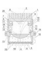
도 1은 입력렌즈의 초점길이 조정과 출력렌즈의 방향각 조절이 가능한 기계광학 장치의 개요도이다. 이 장치를 통해 직사각형 형태를 가진 전자기 방사선의 균일한 빔을 얻을 수 있다.
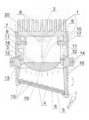
도 2는 상기 장치의 개요도이다. 이 장치를 통해 원의 일부분 형태를 가진 전자기 방사선의 균일한 빔을 얻을 수 있다.
도 3은 상기 장치의 개요도이다. 이 장치를 통해 원 형태를 가진 전자기 방사선의 균일한 빔을 얻을 수 있다.
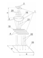
도 4는 장치의 광학시스템에 대한 개요도이다. 방사된 빛이 상당히 폭이 넓고 길이가 긴 직선의 형태를 가지게 하기 위한 전자기 방사선의 광원, 입력렌즈, 출력렌즈의 상대적 위치를 보여준다.
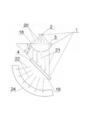
도 5는 상기 광학시스템에 대한 개요도이다. 방사된 빛이 원의 일부분 형태를 가지게 하기 위한 입력렌즈와 출력렌즈의 상대적 위치를 보여준다.
도 6은 상기 광학시스템에 대한 개요도이다. 방사된 빛이 타원형의 원 형태를 가지게 하기 위한 전자기 방사선의 광원, 입력렌즈, 출력렌즈의 상대적 위치를 보여준다.
도 7은 상기 광학시스템에 대한 개요도이다. 방사된 빛이 정사각형의 형태를 가지게 하기 위한 전자기 방사선의 광원, 입력렌즈, 출력렌즈의 상대적 위치를 보여준다.
도 8은 상기 광학시스템에 대한 개요도이다. 방사된 빛이 길이가 넓이의 5배인 직사각형 형태를 가지게 하기 위한 전자기 방사선의 광원, 입력렌즈, 출력렌즈의 상대적 위치를 보여준다.
도 9는 상기 광학시스템에 대한 개요도이다. 방사된 빛이 길이가 넓이의 10배인 직사각형 형태를 가지게 하기 위한 입력렌즈와 출력렌즈의 상대적 위치를 보여준다.
도 10은 도면 4에 있는 광학시스템과 유사한 15개의 광학시스템으로 구성된 광학시스템에 대한 개요도이다. 방사된 빛이 사용자의 필요에 따라 서로 다른 길이를 가진 3개의 직사각형 형태를 가지게 하기 위해 15개의 광학시스템이 5개의 광학시스템이 서로 연결된 그룹으로 나누어지고 하나의 광학시스템이 그들을 제어하는 모습을 보여준다.
도 11은 웜기어와 스트랜드를 통해 전자기 방사선 빔의 형태를 조정하는 시스템에 대한 개요도이다.
도 12는 평면 원통형 출력렌즈로 구성된 패널이다. 패널은 동일한 지름을 가진 여러 개의 평면 원통형 렌즈로 구성된다.
도 13은 평면 원통형 출력렌즈로 구성된 패널의 변형이다. 각 평면 원통형 렌즈는 서로 분리되었고 수직 단면도는 윗면이 둥근 동일한 정사각형을 보여준다.
도 14는 동일 패널의 자세한 "T"이다.
도 15는 평면 원통형 출력렌즈로 구성된 패널의 다른 변형이다. 여러 평면 원통형 출력렌즈가 직선으로 배열되고 서로 접촉하며 직사각형의 판에 장착된다.
도 16은 평면 원통형 출력렌즈로 구성된 패널의 변형이다. 평면 원통형 출력렌즈는 나란히 위치하고 중앙 렌즈 (지름이 가장 큰) 의 양 측면에서 지름이 감소한다.
도 17은 원통형 렌즈로 구성된 면 패널의 변형이다. 원통형 렌즈는 서로 다른 지름을 가진다.
도 18은 옆면은 원의 일부분 모양인 구 모양의 패널이다. 이 패널은 원통형 렌즈로 이루어진다.
도 19는 원통형 렌즈로 이루어진 구 모양의 패널이다. 이 패널은 원통의 옆면에 위치한다.
도 20은 원통형 렌즈로 이루어진 비구면의 패널이다. 이 패널의 옆면은 원 일부분의 형태를 하고 있다.
도 21부터 도 28까지는 다른 입력렌즈의 형태를 보여준다. 형태는 수직축과 수평축에 대해 좌우대칭이거나 비대칭이다.
도 21은 평면과 투시도에서 모두 좌우대칭인 평면원통형렌즈를 보여준다.
도 22는 평면과 상면도 그리고 축단면도에서 좌우대칭인 프레넬 렌즈를 보여준다.
도 23은 볼록함이 각기 다르고 수직면과 투시도에서만 좌우대칭인 양면볼록렌즈를 보여준다.
도 24는 수직면과 투시도에서 좌우대칭인 요철렌즈를 보여준다.
도 25는 양면과 투시도에서 좌우대칭인 양면오목렌즈를 보여준다.
도 26은 수직면과 투시도에서만 좌우대칭인 평면오목렌즈를 보여준다.
도 27은 수직면과 투시도에서 좌우대칭인 평면볼록렌즈를 보여준다.
도 28은 볼록함이 수직과 수평에서 비대칭적인 양면볼록렌즈를 보여준다.The objects of the present invention are illustrated in the examples embodied in the various drawings.
1 is a schematic view of a mechanical optical device capable of adjusting the focal length of the input lens and the direction angle of the output lens. Through this device, a uniform beam of electromagnetic radiation with a rectangular shape can be obtained.
2 is a schematic view of the device. Through this device a uniform beam of electromagnetic radiation in the form of a circle can be obtained.
Figure 3 is a schematic view of the device. Through this device a uniform beam of electromagnetic radiation with a circular shape can be obtained.
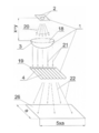
4 is a schematic diagram of an optical system of a device. The relative positions of the light source, input lens, and output lens of the electromagnetic radiation to make the emitted light have a shape of a substantially wide and long straight line.
5 is a schematic view of the optical system. It shows the relative position of the input lens and the output lens to make the emitted light form part of the circle.
6 is a schematic view of the optical system. The relative positions of the light source, input lens, and output lens of electromagnetic radiation to make the emitted light have an elliptical circular shape.
7 is a schematic view of the optical system. The relative positions of the light source, input lens, and output lens of the electromagnetic radiation to make the emitted light form a square are shown.
8 is a schematic diagram of the optical system. The relative positions of the light source, input lens, and output lens of electromagnetic radiation to make the emitted light have a rectangular shape that is five times the length is shown.
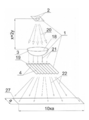
9 is a schematic diagram of the optical system. The relative positions of the input lens and the output lens are shown to make the emitted light have a
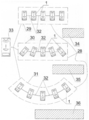
10 is a schematic diagram of an optical system consisting of fifteen optical systems similar to the optical system of FIG. In order for the emitted light to have three rectangular shapes with different lengths according to the user's needs, 15 optical systems show that the five optical systems are divided into connected groups and one optical system controls them.
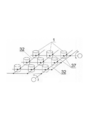
11 is a schematic diagram of a system for adjusting the shape of an electromagnetic radiation beam through a worm gear and a strand.
12 is a panel composed of a planar cylindrical output lens. The panel consists of several flat cylindrical lenses with the same diameter.
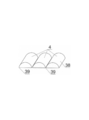
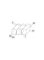
13 is a modification of the panel made up of a flat cylindrical output lens. Each plane cylindrical lens is separated from each other, and the vertical section shows the same square with the top surface rounded.
14 is a detailed "T" of the same panel.
15 is another variation of a panel made up of a planar cylindrical output lens. Several flat cylindrical output lenses are arranged in a straight line and contact each other and mounted on a rectangular plate.
16 is a modification of the panel made up of a flat cylindrical output lens. Flat cylindrical output lenses are located side by side and the diameter decreases on both sides of the center lens (largest diameter).
17 is a modification of a face panel made of a cylindrical lens. Cylindrical lenses have different diameters.
Fig. 18 is a sphere-shaped panel whose side surface is a part of a circle. This panel is made of a cylindrical lens.
19 is a spherical panel made of a cylindrical lens. This panel is located on the side of the cylinder.
20 is an aspherical surface panel made of a cylindrical lens. The side of this panel is in the shape of a circle.
Figures 21 to 28 show the shapes of different input lenses. The shape is symmetrical or asymmetrical with respect to the vertical axis and the horizontal axis.
Figure 21 shows a planar cylindrical lens which is symmetrical in both plan and perspective views.
Fig. 22 shows a Fresnel lens which is horizontally symmetrical in plan, top and axial sectional views. Fig.
Fig. 23 shows a two-sided convex lens having convexity different from each other and symmetrical only in a vertical plane and a perspective view.
Fig. 24 shows a concave-convex lens which is bilaterally symmetrical in a vertical plane and a perspective view.
25 shows a double-sided concave lens which is bilaterally symmetrical on both sides and a perspective view.
Fig. 26 shows a plano-concave lens that is bilaterally symmetrical only in a vertical plane and in a perspective view.
27 shows a planar convex lens which is symmetrical in a vertical plane and in a perspective view.
28 shows a biconvex lens in which the convexity is asymmetric in the vertical and horizontal directions.
입력렌즈로는 가급적 양면볼록렌즈, 요철렌즈, 반사경이나 반사경 장치가 사용된다.As the input lens, a double-convex lens, a concave-convex lens, a reflecting mirror, or a reflecting mirror device is preferably used.
출력렌즈로는 가급적 길이에 따라 일정한 지름을 가진 평면 원통형 렌즈, 길이에 따라 일정한 지름을 가지지만 대안으로 다른 지름을 가질 수 있는 평면 원통형 렌즈, 또는 길이를 따라 다른 지름을 가질 수 있는 평면원통형 렌즈가 사용된다.The output lens is preferably a planar cylindrical lens having a constant diameter along its length, a planar cylindrical lens having a constant diameter along the length but alternatively a different diameter, or a planar cylindrical lens having a different diameter along its length Is used.
원통형 출력 렌즈에서 가급적 서로에게 가해지는 뚜렷한 모서리의 최소 압력에 의하거나, 렌즈의 접촉면을 광택을 흐리게 하거나, 접촉면에 금속 코팅을 씌우거나, 접촉면에 격리요소를 삽입하는 것을 통해 인접 렌즈들을 서로 분리하는 것이 선호된다. By separating the adjacent lenses from each other by applying a minimum pressure of a distinct edge to each other as far as possible from the cylindrical output lens, by blurring the contact surface of the lens, by applying a metal coating to the contact surface, Is preferred.
광원으로는 가급적 가시광선 범위 400~800nm, 자외선 범위 100~400nm, 적외선 범위 800~15000nm 의 빛을 방출하는 전자기 방사선의 광원이 선호되고 전자기 방사선 탐지장치로는 가급적 광 다이오드나 광 트랜지스터가 선호된다. As a light source, a light source of electromagnetic radiation which emits light with a visible light range of 400 to 800 nm, an ultraviolet range of 100 to 400 nm and an infrared range of 800 to 15000 nm is preferred, and a photodiode or a phototransistor is preferably used as an electromagnetic radiation detection apparatus.
가변 초점거리를 가진 입력렌즈를 떠난 광선은 가급적 -30도부터 +30도의 범위에서 평행하거나, 발산하거나, 또는 수렴하는 것이 선호된다.It is preferred that the light leaving the input lens with variable focus distance is parallel, divergent, or converging in the range of -30 degrees to +30 degrees.
원통형 렌즈 패널이 사용되는 경우, 각 렌즈를 다른 인접한 원통형 렌즈로부터의 반사 방사선의 직간접적인 전이로부터 보호하는 것이 선호된다.When a cylindrical lens panel is used, it is preferred to protect each lens from direct or indirect transfer of reflected radiation from other adjacent cylindrical lenses.
반면에 본 발명에 따라 임의의 기하학적 형태를 가진 전자기 방사선의 균일한 빔을 얻는 장치의 주요 개념은 다음 사항에 있다. 광학시스템은 입력수렴렌즈와 반대편에 위치한 인공광원, 광원에서 방출되는 전자기 광선과 출력렌즈나 출력렌즈패널, 상기 광선을 수신하는 가급적 평면원통형 렌즈, 광원이 설치된 하우징, 하우징에 설치된 사이드가드, 사이드가드에 설치된 암, 암의 하단에 단단하게 연결된 수렴입력 렌즈, 하우징이 분리될 수 있게 연결된 회전시스템, 하우징이 또한 분리될 수 있게 연결된 교체할 수 있는 부분, 부분의 하부에 장착된 출력렌즈나 출력렌즈 패널로 구성된다. On the other hand, the main concept of an apparatus for obtaining a uniform beam of electromagnetic radiation with arbitrary geometry in accordance with the present invention is as follows. The optical system includes an artificial light source positioned opposite to the input converging lens, an electromagnetic light beam and an output lens or output lens panel emitted from the light source, a preferably flat cylindrical lens for receiving the light, a housing provided with a light source, a side guard provided on the housing, A converging input lens rigidly connected to the lower end of the arm, a rotation system detachably connected to the housing, a replaceable portion detachably connected to the housing, an output lens or output lens mounted on the lower portion of the housing, Panel.
출력렌즈나 출력렌즈패널을 수렴입력 렌즈의 패널면에 대해서 0도에서 70도의 각도로 교체할 수 있는 부분에 설치할 경우, 몸체의 방향각을 바꿀 수 있는 회전시스템을 제공하고 하우징을 외부차폐수단을 통해 몸체에 단단하게 연결하는 것이 선호된다. When the output lens or output lens panel is installed at a position where it can be changed at an angle of 0 to 70 degrees with respect to the panel surface of the convergent input lens, it is possible to provide a rotation system capable of changing the directional angle of the body, It is preferable to connect to the body firmly.
장치가 하나의 LED 섹션이나 선택된 세로나 횡단 방향으로 0도에서 360도까지의 범위에서 독립적이거나 상호의존적인 조정된 스윙 모션을 가진 광학 시스템을 포함하는 여러 개의 LED 섹션으로 구성되고 변속기가 제공될 경우, 가급적 LED의 수와 목적에 맞게 조정된 변수를 가지며 입력렌즈의 방향, 각도위치 및 초점거리를 조정하는데 사용되는 웜기어 그리고/또는 스트랜드 변속기가 선호된다. If the device consists of several LED sections, including an LED section or an optical system with independent or interdependent adjusted swing motions in the range of 0 to 360 degrees in the selected longitudinal or transverse direction, and the transmission is provided , Worm gears and / or strand transmissions are preferably used to adjust the direction, angular position and focal length of the input lens, with variables adjusted to the number and purpose of the LED, preferably as a function of the input lens.
원통형렌즈 표면의 전적한 만곡 그리고/또는 원통형렌즈 반경의 선택과 렌즈의 적절한 광학 매개변수를 통해 전자기 방사선 빔을 늘릴 수 있었고 제어된 방법으로 빛을 가능한 한 멀리까지 지향하게 할 수 있었다. 그리고 인접한 렌즈들을 적절하게 분리시키고 렌즈의 곡선표면 사이의 접촉면을 감소시켜 요구되는 기하학적 형태로 빛을 투사하는 형태로 높은 수준의 통일성을 지닌 전자기 방사선 빔을 얻을 수 있었다. 여러 렌즈를 통과하면서 여러 접촉면에서 발생하는 방사선의 변형을 렌즈의 분리를 통해 방지하였다. 변형된 방사선은 균일하지 않게 되며, 많은 기존의 장치들은 이 때문에 효과적으로 작동할 수 없었다.
The electromagnetic radiation beam could be extended through the entire curvature of the cylindrical lens surface and / or the choice of the cylindrical lens radius and the appropriate optical parameters of the lens, allowing the light to be directed as far as possible in a controlled manner. And an electromagnetic radiation beam with a high level of uniformity in the form of properly separating adjacent lenses and reducing the contact surface between the curved surfaces of the lens and projecting the light in the required geometrical form. The deformation of the radiation from the various contact surfaces while passing through the lens was prevented through the lens separation. The deformed radiation becomes non-uniform, and many conventional devices have not been able to operate effectively because of this.
본 특허에 관한 설명에서 사용된 용어의 정의는 다음과 같다:The definitions of terms used in the description of this patent are as follows:
광원 : 200~15000 nm 범위의 파장을 지닌 전자기 방사선을 내뿜는 물체를 의미한다. 예를 들어, 반도체 다이오드, 가스배출 튜브, 석영램프, 할로겐 램프, 나트륨 램프, 수은등, 전구, 형광등, 적외선 방사체, 자외선방사 다이오드, 또는 루미노포르. Light source: An object that emits electromagnetic radiation with a wavelength in the range of 200 to 15000 nm. For example, semiconductor diodes, gas exhaust tubes, quartz lamps, halogen lamps, sodium lamps, mercury lamps, bulbs, fluorescent lamps, infrared radiators, ultraviolet radiation diodes, or luminophores.
광학시스템: 적절하게 위치하고 광학장치나 면에 광학 이미지를 만드는데 참여하는 렌즈 형태의 두 개 이상의 광학요소. Optical system: Two or more optical elements in the form of lenses that are appropriately located and participate in making optical images on optical devices or surfaces.
입력렌즈: 렌즈의 수직축 또는 수평축에 대해 대칭적이거나 비대칭적인 광선을 모으는 렌즈를 의미한다.Input lens: means a lens that collects symmetrical or asymmetric rays with respect to the vertical or horizontal axis of the lens.
출력렌즈: 원통형 렌즈 또는 나란히 설치되어 직선으로 서로 접촉하거나 서로 떨어져 있는 일련의 원통형 렌즈를 의미한다.Output lens: means a cylindrical lens or a series of cylindrical lenses mounted side by side and in straight line contact with each other or separated from each other.
원통형 렌즈: 하나의 대칭면이나 구면렌즈를 의미한다. 구면렌즈의 단면은 긴 반원통형 요소나 한 면이 평면이고 지름이 일정하거나 길이에 따라 변화하고 그러한 일련의 렌즈가 공동의 기초를 지닌 단일체인 부분을 가진다.Cylindrical lens: means one symmetrical plane or spherical lens. The cross-section of a spherical lens has a long semi-cylindrical element, or a portion of which the plane is planar and the diameter is constant or varies with length, and such a series of lenses is a monolith with a cavity base.
대칭렌즈: 원통형 평면볼록렌즈, 양면오목렌즈, 양면오목렌즈 등 수평면과 수직면에서 좌우대칭인 렌즈 또는 다양한 볼록함을 지닌 양면볼록렌즈, 보철렌즈, 평면볼록렌즈 등 수직면에서만 좌우대칭인 렌즈 또는 볼록함이 다양한 평면볼록렌즈 등 수평면에서만 좌우대칭인 렌즈를 의미한다.Symmetric Lens: Lens or convex lens which is symmetrical only in vertical plane, such as a cylindrical flat convex lens, a double-side concave lens, a double-side concave lens, a symmetric lens in horizontal or vertical plane or a double-convex lens having various convexities, Refers to a lens that is symmetrical only in the horizontal plane such as various flat convex lenses.
반사요소: 전자기 방사선의 방향을 바꾸거나 전자기 방사선에 형태를 주는 간소화된 반사장치를 의미한다.
Reflective element: Refers to a simplified reflector that redirects or shapes the electromagnetic radiation.
[실시예][Example]
실시예 1Example 1
도 1에 있는 실시 예에 따라 임의의 기하학적 형태를 가진 전자기 방사선의 균일한 빔을 얻기 위해 사용되는 기계광학장치는 다음의 요소로 이루어진 광학시스템(1)을 구성한다. 파장범위 400~800nm 의 가시광선을 방출하는 LED 형태의 광원(2), 좌우대칭인 평면볼록렌즈 형태의 교체할 수 있는 입력렌즈(3), 나란히 위치하고 직선으로 접촉하고 투명한 판 요소(6)에 위치한 평면볼록 원통형 렌즈(5)로 구성된 패널 형태의 교체할 수 있는 출력렌즈(4)로 구성된다. 광원(2)은 냉각 라디에이터(8)와 두 개의 가이드(9)가 있는 하우징(7)과 연결된다. 두 개의 가이드에는 암(11)이 있고 암은 멘드럴(10) 위에 있는 가이드 위에 잘 미끄러지게 설치된다. 상기 암의 하단은 입력렌즈(3)와 단단하게 연결된다. 입력렌즈의 초점거리 "x" 는 변경될 수 있고, 입력렌즈는 핀(12)에 의해 입력렌즈의 각도를 변경시키는 회전시스템(14)의 몸체(13)에 연결된다. 입력렌즈는 변경할 수 있는 부분과 연결된다. 변경할 수 있는 부분(15)은 입력렌즈의 하단에 고정되고 출력렌즈(4)와 외부 냉각 라디에이터(16)가 제공된다. 회전시스템의 몸체(13)는 차폐수단(17)을 통해 하우징(7)에 연결되고 출력렌즈(4)는 입력렌즈(3)의 평면(18)과 평행하게 위치한다. The mechanical optics used to obtain a uniform beam of electromagnetic radiation with arbitrary geometry in accordance with the embodiment of FIG. 1 constitutes an
실시예 2Example 2
도 1에 있는 기계광학 장치의 몸체(13)에 교체할 수 있는 부분(15)이 고정되고, 교체할 수 있는 출력렌즈(4)는 도 2 에 나와있는 것과 같이 입력렌즈(3)의 평면(18)에 대해 45도 보다 적은 각도로 지향된다. The
실시예 3Example 3
도 1에 있는 기계광학장치의 몸체(13)에 교체할 수 있는 부분(15)이 고정되고, 교체할 수 있는 출력렌즈(4)는 도 2에 나와 있는 것과 같이 입력렌즈(3)의 평면(18)에 대해 45도 보다 큰 각도로 지향된다.The
본 발명의 아래의 실시 예는 도 1 ~ 도 3에 있는 예제 장치에서 사용된 광학 시스템(1)을 구성하는 입력렌즈(3), 출력렌즈(4), 및 광원(2)에 따라 다른 형태의 빛 투사와 전자기 방사선의 균일한 빔을 얻는 방법에 관한 것이다:The following embodiments of the present invention can be applied to other types of
실시예 4Example 4
도 1에서 설명한 장치에서 사용된 광학시스템(1)에서, 원통형 출력렌즈(4)의 평면(19)은 수렴 평면볼록 입력렌즈(3)의 평면(18)과 평행하게 위치한다. 주파범위 100~400nm의 자외선을 방출하는 광원(2)에 의해 발생한 전자기 빛(2) 이 입력렌즈(3)에 지향되고, 그 빛은 출력렌즈(4)로 지향된다. 이 결과로, 도 4 에 나와 있는 것과 같이, 출력렌즈를 떠나는 빛(22)은 지속적으로 폭이 넓은 선(23)의 형태로 전자기 빛의 균일한 빔을 얻을 수 있다. In the
실시예 5Example 5
실시예 1과 4에서 설명한 광학시스템(1)에서, 원통형 출력렌즈(4)의 아래면(19)은 수렴평면볼록 입력렌즈(3)의 평면(18)에 대해 35 도의 각도로 위치한다. 파장범위 800~15000nm의 적외선을 방출하는 광원(2)에 의해 발생한 전자기 광선(20)은 입력렌즈(3)로 지향되고, 다시 그 광선(21)은 출력렌즈(4)로 지향된다. 이 결과로, 도 5 에 나와 있는 것과 같이, 출력렌즈를 떠나는 빛(22)은 원의 일부분 형태(24)의 전자기 방사선의 균일한 빔의 형태로 투사된다. In the
실시예 6Example 6
실시예 1~5에서 설명한 광학시스템(1)에서, 원통형 출력렌즈(4)의 아래면(19)은 수렴평면볼록 입력렌즈(3)의 평면(18)에 대해 65 도의 각도로 위치한다. 광원(2)에 의해 발생한 전자기 광선(20)은 입력렌즈(3)로 지향되고, 다시 그 광선(21)은 출력렌즈(4)로 지향된다. 이 결과로 도 6 에 나와 있는 것과 같이, 출력렌즈를 떠나는 빛(22)은 타원형 형태(24)의 전자기 방사선의 균일한 빔의 형태로 투사된다.The
실시예 7Example 7
실시예 1~6에서 설명한 광학시스템(1)에서, 출력렌즈(4)의 아래면(19)은 광원(2)으로부터 "X" 만큼 떨어져 있는 수렴평면볼록 입력렌즈(3)의 평면(18)과 평행하게 위치한다. 그리고 광원에서 발생한 전자기 광선(20)은 입력렌즈(3)로 지향되고, 입력렌즈를 떠난 후, 그 광선(21)은 출력렌즈(4)로 지향된다. 이 결과로 도 7 에 나와 있는 것과 같이, 출력렌즈를 떠나는 빛(22)은 길이와 넓이가 "a" 인 직사각형 형태(25)의 전자기 방사선의 균일한 빔의 형태로 투사된다. In the
실시예 8Example 8
실시예 1~7에서 설명한 (1) 광학시스템에서, 출력렌즈(4)의 아래면(19)은 수렴평면볼록 입력렌즈(3)의 평면(18)과 평행하게 위치한다. 도 4 에 나와 있는 것과 같이 수렴평면볼록 입력렌즈는 광원(2)으로부터 "x + y" 만큼 떨어져 있다. 그리고 광원에서 발생한 전자기 광선(20)은 입력렌즈(3)로 지향되고 입력렌즈를 떠난 후, 광선(21)은 출력렌즈(4)로 지향된다. 이 결과로 도 8 에 나와 있는 것과 같이, 출력렌즈를 떠나는 빛(22)은 길이가 "a" 이고 넓이가 "5×a"인 직사각형 형태(26)의 전자기 방사선의 균일한 빔의 형태로 투사된다. In the optical system described in the first to seventh embodiments, the
실시예 9Example 9
실시예 1~8 에서 설명한 광학시스템(1)에서, 출력렌즈(4)의 아래면(19)은 수렴평면볼록 입력렌즈(3)의 평면(18)과 평행하게 위치한다. 도 8 에 나와 있는 것과 같이 수렴평면볼록 입력렌즈는 광원(2)으로부터 "x + 2y" 만큼 떨어져 있다. 그리고 광원에서 발생한 전자기 광선(16)은 입력렌즈(3)로 지향되고, 입력렌즈를 떠난 후, 그 광선(21)은 출력렌즈(4)로 지향된다. 이 결과로 도 9 에 나와 있는 것과 같이, 출력렌즈를 떠나는 빛(22)은 길이가 "a" 이고 넓이가 "10×a"인 직사각형 형태(27)의 전자기 방사선의 균일한 빔의 형태로 투사된다. In the
실시예 10Example 10
실시예 4에서 설명한 15개의 광학시스템(1)과 일련의 LED(28)는 각각 5개의 광학시스템으로 구성된 3개의 LED 섹션 (29, 30, 31) 으로 나누어지고 스트랜드(32)에 의해 평행하게 상호 연결되고 하나의 공통 광학시스템(33)에 의해 제어된다. 5개의 광학시스템(1)이 서로에 대해 동일하게 지향하고 하나의 면에 위치한 그룹(29)에서는 직사각형 형태(34)의 전자기 방사선의 균일한 빔이 투사된다. 5개의 광학시스템(1)이 서로에 대해 다른 각도로 지향하는 그룹(30)에서는 상기의 직사각형(34) 보다 약 50% 더 긴 직사각형 형태(35)의 전자기 방사선의 균일한 빔이 투사된다. 5개의 광학시스템(1)이 원 부분의 면에 있는 원호에 위치한 그룹(31)에서는 상기의 직사각형(34) 보다 약 100% 더 긴 직사각형 형태(36)의 전자기 방사선의 균일한 빔이 투사된다. 도 12 에 나와 있는 것과 같이 광학시스템(1)의 그룹들(29, 30, 31)은 스트랜드(32)와 도 10과 도 12에 나와 있는 것과 같이 시스템의 위치를 회전을 통해 변경하는 웜 변속기(37)에 의해 서로 연결된다. The fifteen
아래의 실시예에서는 본 발명의 추정 목표를 달성하도록 하는 다른 형태의 출력렌즈가 제시된다:
In the following embodiments, another type of output lens is provided to achieve the estimated goal of the present invention:
실시예 11 Example 11
출력렌즈(4)는 세 개의 대칭 평면원통형 렌즈(38)를 구성한다. 도 12에 나와있는 것과 같이, 대칭 평면원통형 렌즈는 정면에서 직사각형의 반원통형 요소를 가지며 세로 모서리(39)를 통해 서로 접촉한다. The
실시예 12Example 12
출력렌즈(4)는 일련의 직사각형 요소(40)를 구성한다. 도 13과 도 14에 나와 있는 것과 같이, 직사각형 요소는 정면에서 둥근 윗면(42)이 있는 직사각형의 형태(41)를 가지며 옆면(43)에서 다른 직사각형 요소와 그들을 분리시키는 요소(44)를 통해 접촉한다.The
실시예 13Example 13
출력렌즈(4)는 대칭 평면원통형 렌즈(45)로 이루어진 패널을 구성한다. 도 15에 나와 있는 것과 같이, 대칭 평면원통형 렌즈는 투명 판(46)에 결합되고 세로 모서리(47) 를 통해 서로 접촉한다. The
실시예 14Example 14
출력렌즈(4)는 대칭 평면원통형 렌즈(48)로 이루어진 패널을 구성한다. 도 16에 나와있는 것과 같이, 대칭 평면원통형 렌즈는 중앙의 렌즈(49)가 가장 지름이 크고 양 방향으로 지름이 감소하며 거리는 증가한다.The
실시예 15Example 15
출력렌즈(4)는 평면원통형 렌즈(50)로 이루어진 패널을 구성한다. 도 17에 나와 있는 것과 같이, 대칭 평면원통형 렌즈는 측면 모서리(51)를 통해 서로 접촉하고 지름(52)은 감소한다.The
실시예 16Example 16
출력렌즈(4)는 원의 부분 형태의 측면을 가진 구체 패널을 구성한다. 도 18에 나와 있는 것과 같이, 구체 패널은 여러 개의 원통형 요철렌즈(53)로 이루어지고 모서리(54)를 통해 서로 접촉한다.The
실시예 17Example 17
출력렌즈(4)는 원의 부분 형태의 측면을 가진 구체 패널을 구성한다. 도 19에 나와 있는 것과 같이, 구체 패널의 정면에는 동일한 외부치수를 가진 요철렌즈(55)들이 위치하고 요철렌즈들은 세로 모서리(56)를 통해 서로 접촉한다.The
실시예 18Example 18
출력렌즈(4)는 원 형태의 측면을 가진 구체 패널을 구성한다. 도 20에 나와The
있는 것과 같이, 구체 패널은 원통형 요철렌즈(57)로 이루어지고 모서리(58)를 통해 서로 접촉한다.As is the case, the sphere panels consist of
실시예 19Example 19
도 1에 나와 있는 광학시스템을 가진 장치에서, 4 W LED 를 구성하는 광원(2)은 입력렌즈(3)로부터 3cm 떨어진 곳에 위치한다. 입력렌즈로부터 2cm의 거리에 출력렌즈(4) 패널이 위치한다. 출력렌즈 패널은 4mm 지름의 평면볼록 원통형 렌즈를 구성한다. 광원(2), 입력렌즈(3), 출력렌즈(4)의 상대적 위치로 인해, 출력렌즈를 떠나는 빛은 3m 의 거리에서 5m×0.35m 의 치수를 가진 긴 직사각형 형태의 전자기 방사선의 균일한 빔의 형태로 투사된다. In the apparatus having the optical system shown in Fig. 1, the
도 21 ~ 도 28에 나와있는 발명에 따른 아래 광학시스템(1)의 실시예에는, 다양한 형태의 대칭 및 서로 다른 대칭 면이 있는 비대칭 렌즈가 제시된다. 이런 실시예는 사용자의 필요에 따라, 적절한 광학시스템(1)의 조작에 사용될 수 있다: 평면볼록 원통형 렌즈(59); 프레넬 렌즈(60); 대칭 양면볼록렌즈(61); 요철렌즈(62); 양면오목렌즈(63); 평면오목렌즈(64); 비대칭 평면볼록렌즈(65) 및 비대칭 양면오목 렌즈(66).
In the embodiment of the
Claims (18)
An artificial light source 2 emitting light is connected to a power network and an electromagnetic ray 20 is emitted from the light source and a light emitting mode 23, 24, 25, 26, 27, 34, 35, Which is a converging cylindrical flat convex lens having a fixed or adjusted focal length "X " in the form of a uniform beam according to the input lens 3 (36) Is directed to an output lens 4 or output lens panel 4 having a fixed or adjustable position and the output lens is tilted at an "a" angle ranging from 0 to 75 degrees, After passing through the lens or output lens panel 4, the light beams are directed to the surface forming the light-transmission, and the desired light-shading type (23, 24, 25, 26, 27, 34, 35, 36) And is made through a lens optical system consisting of an artificial light source and an input lens. Geometrical form of the method of obtaining a uniform beam of electromagnetic radiation.
A method according to claim 1, characterized in that a double-convex lens (61) is used as the input lens (3).
The method according to claim 1, characterized in that the concave-convex lens (62) is used as the input lens (3) to obtain a uniform beam of electromagnetic radiation of arbitrary geometry.
2. A method according to claim 1, characterized in that a reflective or reflective system is used as the input lens (3).
Method according to claim 1, characterized in that a series of planar cylindrical lenses (38) with a constant diameter (45) along the length are used as the output lens (4) to obtain a uniform beam of electromagnetic radiation of arbitrary geometry .
Method according to claim 1, characterized in that a series of planar cylindrical lenses (48) are used as the output lens (4) instead of a constant diameter along the length, but in which a uniform beam of electromagnetic radiation of arbitrary geometrical form .
A method according to claim 1, characterized in that a series of planar cylindrical lenses (50) of varying diameter along the length are used as the output lens (4).
8. The output lens as claimed in claim 1, 6 or 7, characterized in that the output lens uses a series of cylindrical output lenses (4), the sharp edges (39, 42, 47, 51, 40, 45 (see FIG. 4) through the minimum pressure of the lens 54, 56, 58, by dimming the contact surface of the lens, by applying a metal coating to the contact surface, , 48, 50, 53, 55, 57 are separated from one another.
An arbitrary optical fiber according to claim 1, characterized in that electromagnetic radiation, which emits light in the visible light wavelength range of 400 to 800 nm, the ultraviolet wavelength range of 100 to 400 nm and the infrared wavelength range of 800 to 1500 nm, is used as the artificial light source (2) A method of obtaining a uniform beam of electromagnetic radiation in geometric form.
A method according to claim 1, characterized in that the detector of electromagnetic radiation in which a photodiode or phototransistor is used is used as an artificial light source (2).
2. The optical system according to claim 1, characterized in that the electromagnetic rays (20) leaving the input lens (3) having a variable focal length of the optical system (1) are parallel, divergent, or converge in the range of -30 to +30 degrees To obtain a uniform beam of electromagnetic radiation of any geometric shape.
2. The apparatus according to claim 1, wherein the output lens panel uses a cylindrical lens panel (4), wherein each lens of the cylindrical lens panel extends from one cylindrical lens (38,40,45,48,50) to another adjacent cylindrical lens , 40, 45, 48, 50) to prevent the direct or indirect transfer of the reflected radiation into the beam of radiation.
상기 광원의 반대편에 위치한 수렴하는 입력렌즈(3);와,
상기 광원이 방출하는 전자기 광선(20);와,
출력렌즈(4) 또는 출력렌즈패널(4);로 구성되는 광학시스템(1)으로서,
상기 출력렌즈(4) 또는 출력렌즈패널(4)은 상기 광선을 받고 일련의 출력렌즈 (45, 48, 52)를 구성하며, 광원(2)이 하우징(7)에 설치되고 멘드럴(10) 위에 있는 가이드(9) 위에 잘 미끄러지게 암(11)이 설치되며, 상기 암의 하단은 수렴하는 입력렌즈(3)와 단단하게 연결되며, 하우징(7)은 회전시스템(14)의 몸체(13)와 분리할 수 있게 연결되고, 회전시스템의 몸체는 변경할 수 있는 부분(15)과 분리할 수 있게 연결되며, 변경할 수 없는 부분의 하단은 출력렌즈(4)나 출력렌즈패널(4)을 장착해서 상기 출력렌즈나 출력렌즈패널은 장치의 하우징(7)에 대해 회전할 수 있는 광학시스템(1);을 구비한 것을 특징으로 하는 임의의 기하학적 형태의 전자기 방사선의 균일한 빔을 얻는 장치.
An artificial light source 2,
A converging input lens 3 located on the opposite side of the light source,
An electromagnetic ray (20) emitted by the light source;
An optical system (1) comprising an output lens (4) or an output lens panel (4)
The output lens 4 or the output lens panel 4 receives the light and constitutes a series of output lenses 45, 48 and 52. The light source 2 is installed in the housing 7, The lower end of the arm is rigidly connected to the converging input lens 3 and the housing 7 is connected to the body 13 of the rotation system 14 The body of the rotating system is detachably connected to the changeable portion 15 and the lower end of the unchangeable portion is fitted with the output lens 4 or the output lens panel 4 Characterized in that said output lens or output lens panel comprises an optical system (1) rotatable with respect to a housing (7) of the apparatus.
14. The apparatus according to claim 13, wherein the output lens (4) and the output lens panel (4) are provided in a part (15) which can be replaced at an angle of 0 to 70 degrees with respect to a plane (18) Wherein the beam of electromagnetic radiation is of a geometric shape.
14. Apparatus according to claim 13, characterized in that the body (13) is provided with a rotation system (14) capable of changing the angular position of the body.
14. Apparatus according to claim 13, characterized in that said housing (7) is rigidly connected to the body (13) via external shielding means (17).
The optical system according to claim 13, wherein the optical system (1) comprises one LED section (29, 30, 31) or a series of LED sections (39) Characterized in that it includes the ability to perform independent or interdependent coordinated swing motions in the range from 0 to 360 degrees in the longitudinal or transverse direction, A device for obtaining a beam.
상기 광학시스템(1)은
변속기로서 웜기어(37) 혹은 스트랜드 변속기(32) 각각, 혹은 웜기어(37)와 스트렌드 변속기(32)를 함께 제공할 수 있으며, 웜기어 또는 스트랜드 변속기는 LED 섹션(29, 30, 31)의 수와 목적에 맞게 조정된 변수를 가지며 입력렌즈(3)의 방향, 각도위치 및 초점거리를 조정하는데 사용되는 것을 특징으로 하는 임의의 기하학적 형태의 전자기 방사선의 균일한 빔을 얻는 장치.
17. The method according to any one of claims 13 to 16,
The optical system (1)
The worm gear 37 or the strand transmission may be provided as a transmission with the worm gear 37 or the strand transmission 32 or the worm gear 37 and the strand transmission 32 respectively and the worm gear or the strand transmission may be provided with the number of the LED sections 29, Is used to adjust the direction, angular position, and focal length of the input lens (3) with a purpose-adjusted variable, to obtain a uniform beam of electromagnetic radiation of any geometric form.
Applications Claiming Priority (3)
| Application Number | Priority Date | Filing Date | Title |
|---|---|---|---|
| PLP.395649 | 2011-07-13 | ||
| PL395649A PL224044B1 (en) | 2011-07-13 | 2011-07-13 | Method for obtaining a homogeneous beam of electromagnetic radiation of any geometrical shape and the mechanical-optical device to apply this method |
| PCT/PL2012/000048 WO2013009197A1 (en) | 2011-07-13 | 2012-06-25 | A method of obtaining a uniform beam of electromagnetic radiation of arbitrary geometrical shape and a mechanical-optical device for application of this method |
Publications (1)
| Publication Number | Publication Date |
|---|---|
| KR20140051925A true KR20140051925A (en) | 2014-05-02 |
Family
ID=46705005
Family Applications (1)
| Application Number | Title | Priority Date | Filing Date |
|---|---|---|---|
| KR1020147002712A Withdrawn KR20140051925A (en) | 2011-07-13 | 2012-06-25 | A method of obtaining a uniform beam of electromagnetic radiation of arbitrary geometrical shape and a mechanical-optical device for application of this method |
Country Status (10)
| Country | Link |
|---|---|
| US (1) | US20140252249A1 (en) |
| EP (1) | EP2732207B1 (en) |
| JP (1) | JP2014524119A (en) |
| KR (1) | KR20140051925A (en) |
| CN (1) | CN103649632A (en) |
| AU (1) | AU2012281262A1 (en) |
| CA (1) | CA2840374A1 (en) |
| PL (2) | PL224044B1 (en) |
| RU (1) | RU2014101645A (en) |
| WO (1) | WO2013009197A1 (en) |
Families Citing this family (34)
| Publication number | Priority date | Publication date | Assignee | Title |
|---|---|---|---|---|
| ITNA20130030A1 (en) * | 2013-05-27 | 2014-11-28 | Studio Trasversale Srl | LAMP EQUIPPED WITH A LENS HOLDER PLATE, INCLINABLE BY A LEVER POSITIONED ON A GRADUATED SCALE, FOR THE VARIATION OF THE LUMINOUS EFFECT |
| ITMI20131756A1 (en) * | 2013-10-22 | 2015-04-23 | Gewiss Spa | LED LIGHTING DEVICE WITH MODULAR OPTICAL SYSTEM |
| US9816687B2 (en) * | 2015-09-24 | 2017-11-14 | Intel Corporation | MEMS LED zoom |
| KR20170041359A (en) * | 2015-10-07 | 2017-04-17 | 엘지이노텍 주식회사 | An illumination appratus |
| KR101779082B1 (en) * | 2015-12-31 | 2017-09-26 | 김다두 | Collimate lens assembly |
| JP6188969B1 (en) * | 2016-01-07 | 2017-08-30 | 三菱電機株式会社 | Ultraviolet sterilizer and air conditioner using the same |
| JP6114449B1 (en) * | 2016-08-30 | 2017-04-12 | 務 大谷 | Light decoration |
| WO2018060049A1 (en) * | 2016-09-29 | 2018-04-05 | Philips Lighting Holding B.V. | Lighting device. |
| US20180156423A1 (en) * | 2016-12-06 | 2018-06-07 | Lumenpulse Lighting Inc. | Adjustable wall washing illumination assembly |
| KR200483780Y1 (en) * | 2016-12-19 | 2017-07-03 | 윤현중 | Signborad having a side light emitting unit |
| EP3339722B1 (en) * | 2016-12-20 | 2019-08-14 | Obelux Oy | Obstruction illuminator, obstruction illuminator assembly and installation method |
| EP3571398A1 (en) * | 2017-02-22 | 2019-11-27 | Siemens Gamesa Renewable Energy A/S | A tower for a wind turbine and a wind turbine |
| TWI639798B (en) * | 2017-09-28 | 2018-11-01 | 周聰明 | LED light source guiding device |
| CN107940393A (en) * | 2017-11-21 | 2018-04-20 | 李丹 | LED car lamp and its concentrator |
| DE102019002540A1 (en) * | 2018-04-11 | 2019-10-17 | Canon Kabushiki Kaisha | ILLUMINATION DEVICE |
| US10527249B2 (en) | 2018-05-31 | 2020-01-07 | North American Lighting, Inc. | Vehicle lamp and projection lens |
| CN109092644A (en) * | 2018-10-24 | 2018-12-28 | 深圳市华星光电技术有限公司 | A kind of solidification equipment |
| CN109268771A (en) * | 2018-10-30 | 2019-01-25 | 杭州军莹新能源科技有限公司 | A kind of the automatic intelligent LED light and its usage mode of cloud computing manipulation |
| CN109751521B (en) * | 2019-03-07 | 2020-07-28 | 维沃移动通信有限公司 | Light module and mobile terminal |
| CN109973850A (en) * | 2019-04-19 | 2019-07-05 | 赛尔富电子有限公司 | A kind of linear light source headlamp |
| US11029001B2 (en) * | 2019-08-21 | 2021-06-08 | RAB Lighting Inc. | Apparatuses and methods for changing lighting fixture dimensions |
| US10724720B1 (en) | 2019-09-16 | 2020-07-28 | Elemental LED, Inc. | Multi-purpose channels for linear lighting |
| US10724719B1 (en) | 2019-09-16 | 2020-07-28 | Elemental LED, Inc. | Channel system for linear lighting |
| US10663148B1 (en) | 2019-09-16 | 2020-05-26 | Elemental LED, Inc. | Modular channel for linear lighting |
| US11835202B2 (en) * | 2019-11-21 | 2023-12-05 | Mitsubishi Electric Corporation | Illumination device |
| US11118752B2 (en) * | 2020-01-27 | 2021-09-14 | Elemental LED, Inc. | Flexible cover for linear lighting channels |
| RU201642U1 (en) * | 2020-07-28 | 2020-12-24 | Общество с ограниченной ответственностью «Центрсвет» | LAMP |
| CN112051697A (en) * | 2020-09-16 | 2020-12-08 | 珠海格力电器股份有限公司 | Control system and method of light supplementing light source and terminal |
| CN112595740B (en) * | 2020-12-17 | 2025-02-14 | 西安交通大学 | An independent multi-point quartz lamp thermal assessment device based on focused heating |
| US11428398B1 (en) * | 2021-06-21 | 2022-08-30 | Troy-CSL Lighting Inc. | Adjustable lighting device with further optic |
| CN114164780B (en) * | 2021-12-24 | 2024-07-30 | 浙江路光科技有限公司 | Electro-optical long afterglow light accumulating material road surface and pattern and construction method |
| US12618575B2 (en) * | 2022-05-18 | 2026-05-05 | Uvc Science, Inc. | HVAC UVC LED projection unit for HVAC devices |
| DE102022122513A1 (en) * | 2022-09-06 | 2024-03-07 | Methode Electronics Malta Ltd. | Modular system for indirect lighting |
| WO2024054981A1 (en) * | 2022-09-08 | 2024-03-14 | Arizona Board Of Regents On Behalf Of The University Of Arizona | Smart programmable ultraviolet germicidal irradiation system and method |
Family Cites Families (14)
| Publication number | Priority date | Publication date | Assignee | Title |
|---|---|---|---|---|
| US1771844A (en) * | 1927-10-11 | 1930-07-29 | Eilenberg Sigmund | Photographic apparatus |
| PL78483B2 (en) | 1972-10-11 | 1975-06-30 | ||
| DE3431772C1 (en) * | 1984-08-29 | 1993-04-15 | Ulo-Werk Moritz Ullmann Gmbh & Co Kg, 7340 Geislingen | Vehicle lights, in particular rear lights for motor vehicles |
| DE29804251U1 (en) * | 1998-03-10 | 1998-05-07 | Siemens AG, 80333 München | Headlights |
| PL186117B1 (en) | 1998-04-10 | 2003-10-31 | Krzysztof Cichosz | Optical radiation condenser |
| US6947226B2 (en) * | 2001-05-09 | 2005-09-20 | Hamamatsu Photonics K.K. | Optical lens-use base material, optical lens, and method of producing optical lens |
| US7150530B2 (en) * | 2003-05-21 | 2006-12-19 | Alcon, Inc. | Variable spot size illuminator having a zoom lens |
| JP4376289B2 (en) * | 2005-06-01 | 2009-12-02 | シーシーエス株式会社 | Light irradiation device |
| TWI308627B (en) * | 2006-12-05 | 2009-04-11 | Ind Tech Res Inst | Illumination device of flexible lighting angle |
| WO2008081389A1 (en) * | 2006-12-29 | 2008-07-10 | Koninklijke Philips Electronics N.V. | Floodlight with tiltable beam. |
| IT1391091B1 (en) * | 2008-07-15 | 2011-11-18 | Fraen Corp Srl | LIGHTING DEVICE WITH ADJUSTABLE LIGHTING, IN PARTICULAR FOR AN ELECTRIC TORCH |
| DE102009034841B4 (en) * | 2009-07-27 | 2020-11-26 | Emz-Hanauer Gmbh & Co. Kgaa | Light emitting device for a drum of a household appliance |
| DE102009050395A1 (en) * | 2009-10-22 | 2011-04-28 | Götz, Christian | LED lamp with infinitely adjustable beam angle |
| AT509016B1 (en) * | 2009-11-02 | 2012-12-15 | Mannheim Volker Dr | LIGHTING WITH AT LEAST ONE LED |
-
2011
- 2011-07-13 PL PL395649A patent/PL224044B1/en unknown
-
2012
- 2012-06-25 EP EP12748579.5A patent/EP2732207B1/en active Active
- 2012-06-25 CA CA2840374A patent/CA2840374A1/en not_active Abandoned
- 2012-06-25 PL PL12748579T patent/PL2732207T3/en unknown
- 2012-06-25 US US14/129,622 patent/US20140252249A1/en not_active Abandoned
- 2012-06-25 RU RU2014101645/07A patent/RU2014101645A/en not_active Application Discontinuation
- 2012-06-25 AU AU2012281262A patent/AU2012281262A1/en not_active Abandoned
- 2012-06-25 KR KR1020147002712A patent/KR20140051925A/en not_active Withdrawn
- 2012-06-25 CN CN201280034557.6A patent/CN103649632A/en active Pending
- 2012-06-25 JP JP2014520159A patent/JP2014524119A/en active Pending
- 2012-06-25 WO PCT/PL2012/000048 patent/WO2013009197A1/en not_active Ceased
Also Published As
| Publication number | Publication date |
|---|---|
| PL395649A1 (en) | 2013-01-21 |
| PL2732207T3 (en) | 2019-05-31 |
| US20140252249A1 (en) | 2014-09-11 |
| AU2012281262A1 (en) | 2014-01-16 |
| CN103649632A (en) | 2014-03-19 |
| RU2014101645A (en) | 2015-09-10 |
| WO2013009197A1 (en) | 2013-01-17 |
| JP2014524119A (en) | 2014-09-18 |
| CA2840374A1 (en) | 2013-01-17 |
| WO2013009197A4 (en) | 2013-02-14 |
| EP2732207A1 (en) | 2014-05-21 |
| PL224044B1 (en) | 2016-11-30 |
| EP2732207B1 (en) | 2018-10-24 |
Similar Documents
| Publication | Publication Date | Title |
|---|---|---|
| EP2732207B1 (en) | A method of obtaining a uniform beam of electromagnetic radiation of arbitrary geometrical shape and a mechanical-optical device for application of this method | |
| KR200479892Y1 (en) | Illumination device with maximized condensing effect | |
| CN103998859B (en) | Concentrating systems with multiple reflector pairs | |
| US9557099B2 (en) | Optical lens and lighting device | |
| KR101109581B1 (en) | Wide icicle type light adjusting lens for diffusing light of led | |
| CN108139062B (en) | Lighting system and method of generating light output | |
| KR20120093271A (en) | Lens for asymmetrical light beam generation | |
| US20170146214A1 (en) | Microstructure-Based Diffusers for Creating Batwing Lighting Patterns | |
| US8075162B2 (en) | Zoom luminaire with compact non-imaging lens-mirror optics | |
| JP2000193809A (en) | Light distribution control panel and apparatus using it | |
| CN102980133A (en) | Photo-shaping by LED light source | |
| CN103471033B (en) | LED (light emitting diode) lens and lens module thereof | |
| TWI322868B (en) | ||
| US8136973B2 (en) | Lighting apparatus | |
| US5384881A (en) | Multi-lens fiber optic luminaire | |
| CN219473486U (en) | Intelligent lamp | |
| CN207080826U (en) | A compound total reflection LED spotlight lens | |
| KR101340679B1 (en) | Reflector with a structure of guide matrix reflecting surface for use of light device of high intensity discharge | |
| CN108139577B (en) | LED module with output lens | |
| JP3082587U (en) | LED signal light | |
| CN202972916U (en) | Roof lighting optical system | |
| JPS6296914A (en) | Illuminating device by sunbeam | |
| CN107062026B (en) | Compound total reflection LED shot-light lens | |
| RU186552U1 (en) | PROJECTOR TYPE LIGHTING INSTRUMENT | |
| RU2543528C2 (en) | Optical system for secondary light-emitting diode optics |
Legal Events
| Date | Code | Title | Description |
|---|---|---|---|
| PA0105 | International application |
Patent event date: 20140129 Patent event code: PA01051R01D Comment text: International Patent Application |
|
| PG1501 | Laying open of application | ||
| PC1203 | Withdrawal of no request for examination | ||
| WITN | Application deemed withdrawn, e.g. because no request for examination was filed or no examination fee was paid |