KR20140077112A - Sn alloy plating apparatus and method - Google Patents
Sn alloy plating apparatus and method Download PDFInfo
- Publication number
- KR20140077112A KR20140077112A KR1020130153140A KR20130153140A KR20140077112A KR 20140077112 A KR20140077112 A KR 20140077112A KR 1020130153140 A KR1020130153140 A KR 1020130153140A KR 20130153140 A KR20130153140 A KR 20130153140A KR 20140077112 A KR20140077112 A KR 20140077112A
- Authority
- KR
- South Korea
- Prior art keywords
- anode
- liquid
- chamber
- alloy plating
- solution
- Prior art date
- Legal status (The legal status is an assumption and is not a legal conclusion. Google has not performed a legal analysis and makes no representation as to the accuracy of the status listed.)
- Granted
Links
Images




Classifications
-
- C—CHEMISTRY; METALLURGY
- C25—ELECTROLYTIC OR ELECTROPHORETIC PROCESSES; APPARATUS THEREFOR
- C25D—PROCESSES FOR THE ELECTROLYTIC OR ELECTROPHORETIC PRODUCTION OF COATINGS; ELECTROFORMING; APPARATUS THEREFOR
- C25D17/00—Constructional parts, or assemblies thereof, of cells for electrolytic coating
-
- C—CHEMISTRY; METALLURGY
- C25—ELECTROLYTIC OR ELECTROPHORETIC PROCESSES; APPARATUS THEREFOR
- C25D—PROCESSES FOR THE ELECTROLYTIC OR ELECTROPHORETIC PRODUCTION OF COATINGS; ELECTROFORMING; APPARATUS THEREFOR
- C25D21/00—Processes for servicing or operating cells for electrolytic coating
- C25D21/12—Process control or regulation
- C25D21/14—Controlled addition of electrolyte components
-
- C—CHEMISTRY; METALLURGY
- C25—ELECTROLYTIC OR ELECTROPHORETIC PROCESSES; APPARATUS THEREFOR
- C25D—PROCESSES FOR THE ELECTROLYTIC OR ELECTROPHORETIC PRODUCTION OF COATINGS; ELECTROFORMING; APPARATUS THEREFOR
- C25D17/00—Constructional parts, or assemblies thereof, of cells for electrolytic coating
- C25D17/002—Cell separation, e.g. membranes, diaphragms
-
- C—CHEMISTRY; METALLURGY
- C25—ELECTROLYTIC OR ELECTROPHORETIC PROCESSES; APPARATUS THEREFOR
- C25D—PROCESSES FOR THE ELECTROLYTIC OR ELECTROPHORETIC PRODUCTION OF COATINGS; ELECTROFORMING; APPARATUS THEREFOR
- C25D21/00—Processes for servicing or operating cells for electrolytic coating
- C25D21/10—Agitating of electrolytes; Moving of racks
-
- C—CHEMISTRY; METALLURGY
- C25—ELECTROLYTIC OR ELECTROPHORETIC PROCESSES; APPARATUS THEREFOR
- C25D—PROCESSES FOR THE ELECTROLYTIC OR ELECTROPHORETIC PRODUCTION OF COATINGS; ELECTROFORMING; APPARATUS THEREFOR
- C25D21/00—Processes for servicing or operating cells for electrolytic coating
- C25D21/16—Regeneration of process solutions
- C25D21/18—Regeneration of process solutions of electrolytes
-
- C—CHEMISTRY; METALLURGY
- C25—ELECTROLYTIC OR ELECTROPHORETIC PROCESSES; APPARATUS THEREFOR
- C25D—PROCESSES FOR THE ELECTROLYTIC OR ELECTROPHORETIC PRODUCTION OF COATINGS; ELECTROFORMING; APPARATUS THEREFOR
- C25D3/00—Electroplating: Baths therefor
- C25D3/02—Electroplating: Baths therefor from solutions
- C25D3/30—Electroplating: Baths therefor from solutions of tin
-
- C—CHEMISTRY; METALLURGY
- C25—ELECTROLYTIC OR ELECTROPHORETIC PROCESSES; APPARATUS THEREFOR
- C25D—PROCESSES FOR THE ELECTROLYTIC OR ELECTROPHORETIC PRODUCTION OF COATINGS; ELECTROFORMING; APPARATUS THEREFOR
- C25D5/00—Electroplating characterised by the process; Pretreatment or after-treatment of workpieces
- C25D5/003—Electroplating using gases, e.g. pressure influence
-
- C—CHEMISTRY; METALLURGY
- C25—ELECTROLYTIC OR ELECTROPHORETIC PROCESSES; APPARATUS THEREFOR
- C25D—PROCESSES FOR THE ELECTROLYTIC OR ELECTROPHORETIC PRODUCTION OF COATINGS; ELECTROFORMING; APPARATUS THEREFOR
- C25D17/00—Constructional parts, or assemblies thereof, of cells for electrolytic coating
- C25D17/001—Apparatus specially adapted for electrolytic coating of wafers, e.g. semiconductors or solar cells
-
- C—CHEMISTRY; METALLURGY
- C25—ELECTROLYTIC OR ELECTROPHORETIC PROCESSES; APPARATUS THEREFOR
- C25D—PROCESSES FOR THE ELECTROLYTIC OR ELECTROPHORETIC PRODUCTION OF COATINGS; ELECTROFORMING; APPARATUS THEREFOR
- C25D17/00—Constructional parts, or assemblies thereof, of cells for electrolytic coating
- C25D17/008—Current shielding devices
Landscapes
- Chemical & Material Sciences (AREA)
- Engineering & Computer Science (AREA)
- Chemical Kinetics & Catalysis (AREA)
- Electrochemistry (AREA)
- Materials Engineering (AREA)
- Metallurgy (AREA)
- Organic Chemistry (AREA)
- Automation & Control Theory (AREA)
- Electroplating Methods And Accessories (AREA)
- Electrolytic Production Of Non-Metals, Compounds, Apparatuses Therefor (AREA)
Abstract
Description
본 발명은, Sn과 Sn보다 귀한 금속의 합금, 예컨대 납 프리로서, 납땜성이 양호한 Sn-Ag 합금으로 이루어진 도금막을 기판 표면에 성막하는 데 사용되는 Sn 합금 도금 장치 및 방법에 관한 것이다.The present invention relates to a Sn alloy plating apparatus and method used for forming a plating film made of a Sn-Ag alloy, which is a precious metal rather than Sn and Sn, for example, a lead-free solder.
Sn(주석)과 Sn보다 귀한 금속의 합금, 예컨대 Sn과 Ag(은)의 합금인 Sn-Ag 합금을 전기 도금으로 기판 표면에 성막하고, Sn-Ag 합금으로 이루어진 도금막을, 납 프리의 땜납 범프에 사용하는 것이 알려져 있다. 이 Sn-Ag 합금 도금에서는, Sn 이온과 Ag 이온을 갖는 Sn-Ag 합금 도금액 중에 침지시키면서 서로 대향시켜 배치한 애노드와 기판 표면 사이에 전압을 인가하여, 기판 표면에 Sn-Ag 합금 도금막을 성막하도록 하고 있다. Sn과 Sn보다 귀한 금속의 합금으로는, Sn-Ag 합금 외에, Sn과 구리(Cu)의 합금인 Sn-Cu 합금이나, Sn과 Bi(비스무트)의 합금인 Sn-Bi 합금 등을 들 수 있다.A Sn-Ag alloy, which is an alloy of Sn (tin) and a metal that is more precious than Sn, for example, an alloy of Sn and Ag (silver) is formed on the surface of the substrate by electroplating and a plating film made of Sn- Is known. In this Sn-Ag alloy plating, a voltage is applied between the anode and the substrate surface so as to be opposed to each other while being immersed in a Sn-Ag alloy plating solution having Sn ions and Ag ions to form a Sn-Ag alloy plating film on the substrate surface . Examples of the alloy of Sn and Sn that are more valuable than Sn include Sn-Ag alloy, Sn-Cu alloy which is an alloy of Sn and Cu, Sn-Bi alloy which is an alloy of Sn and Bi (bismuth) .
이러한 Sn과 Sn보다 귀한 금속의 합금의 도금에서는, 애노드로서, 불용해성 애노드를 이용하는 경우가 많다. 그것은, 애노드로서, Sn을 재질로 하는 가용성 애노드(Sn 애노드)를 사용하면, Sn보다 귀한 금속이 Sn 애노드 표면에 치환 석출되어, 금속 성분 농도의 불안정화나 도금액의 오염과 같은 문제가 생기기 때문이다.In the plating of an alloy of a metal that is more valuable than Sn and Sn, an insoluble anode is often used as the anode. This is because, when a soluble anode (Sn anode) made of Sn as the anode is used, a metal more precious than Sn is deposited on the surface of the Sn anode to cause problems such as destabilization of the metal component concentration and contamination of the plating solution.
Sn을 재질로 하는 가용성 애노드(Sn 애노드)를 사용한 Sn 합금 도금 방법으로서, 내부에 Sn 애노드를 배치한 애노드실을 음이온 교환막을 개재시켜 도금조로부터 격리하고, 애노드실 내에 Sn 도금액, 산 또는 그의 염을 수용하고, 도금조 내에 Sn 합금 도금액을 수용하여, 애노드실 내의 Sn 이온을 도금조 내의 Sn 합금 도금액에 반송 펌프에 의해 송급할 수 있도록 한 것(일본 특허 제4441725호 공보 참조)이나, 도금조 내에서 Sn 애노드를 양이온 교환막으로 형성된 애노드백 또는 박스로 격리한 상태로, 도금조 내에 배치한 피도금물에 도금을 행하도록 한 것(일본 특허 제3368860호 공보 참조)이 제안되어 있다.An Sn alloy plating method using a soluble anode (Sn anode) made of Sn, comprising the steps of: isolating an anode chamber in which an Sn anode is disposed, from an electroplating bath through an anion exchange membrane; (Refer to Japanese Patent No. 4441725), a plating bath containing a Sn alloy plating solution in which a Sn ion in the anode chamber can be fed to a Sn alloy plating solution in a plating bath by a return pump (See Japanese Patent No. 3368860) has been proposed in which an object to be plated placed in a plating tank is plated with an Sn anode isolated by an anode bag or box formed of a cation exchange membrane.
또한, 도금조에 부속하여, 열화 요인이 되는 물질이 캐소드실에 확산되지 않도록 캐소드실과 애노드실을 격막 또는 격벽에 의해 분리한 보조조를 마련하고, 이 보조조에서, 애노드실 내의 도금액[양극액(陽極液)]에 Sn 이온을 보급하도록 한 Sn-Ag 합금 도금 방법이 제안되어 있다(일본 특허 공개 평11-21692호 공보 참조).Further, an auxiliary tank, which is separate from the cathode chamber and the anode chamber by a diaphragm or a partition wall, is provided in the plating vessel so that the deteriorating substance is not diffused into the cathode chamber. In this auxiliary tank, the plating liquid in the anode chamber An anolyte) is supplied to a Sn-Ag alloy plating method (see Japanese Unexamined Patent Publication No. 11-21692).
본 발명자들은, 일본 특허 제4441725호 공보에 기재된 바와 같이, 애노드실과 캐소드실을 음이온 교환막으로 격리하고, 애노드실 내에 저장한 Sn 이온 및 산 또는 그의 염을 포함하는 전해액(애노드액) 중에 Sn 애노드를 배치하여 Sn 이온을 용해시키고, 그 Sn 이온을 캐소드측으로 이송하는 방법에서는, 애노드실 내에서 Sn 이온을 안정적으로 애노드액 중에 용해시키기 위해, 애노드실 내의 애노드액의 산농도를 관리하는 것이 중요하다는 것을 발견했다. 또한, 일본 특허 제4441725호 공보에 기재된 방법에서는, Sn 이온을 이송하기 위해 펌프 등의 보급 장치 및 보급로를 필요로 하는 점에서, 장치가 구조적으로 복잡해진다는 문제도 있다.As described in Japanese Patent No. 4441725, the present inventors have found that when an anode chamber and a cathode chamber are separated by an anion exchange membrane and an Sn anode stored in an anode chamber and an electrolyte solution (anolyte solution) containing an acid or a salt thereof It is important to control the acid concentration of the anolyte in the anode chamber in order to stably dissolve Sn ions in the anode chamber in the anode chamber in the method of dissolving the Sn ions by arranging the Sn ions in the anode chamber found. Further, in the method described in Japanese Patent No. 4441725, there is also a problem that the apparatus becomes structurally complicated in that it needs a supply device such as a pump for supplying Sn ions and a supply path.
본 발명은, 상기 사정을 감안하여 이루어진 것으로서, Sn 합금 도금액에 Sn 이온과 함께 공급되는 애노드액의 Sn 이온의 농도와, 2가의 Sn 이온과 착체를 형성하는 산의 농도를 적정하게 관리함으로써, Sn 합금 도금액의 관리를 비교적 용이하게 하고, 게다가 장치를 간소화할 수 있도록 한 Sn 합금 도금 장치 및 방법을 제공하는 것을 목적으로 한다.The present invention has been made in view of the above circumstances, and it is an object of the present invention to provide a Sn alloy plating solution containing Sn It is an object of the present invention to provide a Sn alloy plating apparatus and method which can relatively easily manage the alloy plating solution and simplify the apparatus.
Sn 합금 도금 장치는, 도금조의 내부를, Sn 합금 도금액을 유지하고 상기 Sn 합금 도금액에 캐소드가 되는 기판을 침지시키는 캐소드실과, Sn 이온 및 2가의 Sn 이온과 착체를 형성하는 산을 포함하는 애노드액을 유지하고 Sn을 재질로 한 Sn 애노드를 상기 애노드액에 침지시키는 애노드실로 격리하는 음이온 교환막과, 상기 애노드실 내에 상기 산을 포함하는 전해액을 공급하는 전해액 공급 라인을 포함하며, 상기 전해액 공급 라인은, 상기 애노드실 내의 애노드액의 Sn 이온 농도가 정해진 값 이상이면서 상기 산의 농도가 허용치보다 낮아지지 않도록, 상기 애노드실 내에 상기 전해액을 공급하고, 이 전해액의 공급에 따라서 증가된 상기 애노드실 내의 애노드액을 상기 Sn 합금 도금액에 공급한다.Sn alloy plating apparatus comprises a cathode chamber for holding a Sn alloy plating liquid and immersing a substrate to be a cathode in the Sn alloy plating liquid, an anode liquid containing an Sn ion and an acid forming a complex with Sn ion And an electrolyte solution supply line for supplying an electrolyte solution containing the acid into the anode chamber, wherein the electrolyte solution supply line includes an electrolyte solution supplying line for supplying an electrolyte solution containing the acid to the anode chamber, , The electrolytic solution is supplied into the anode chamber so that the concentration of Sn ions in the anode liquid in the anode chamber is equal to or higher than a predetermined value and the concentration of the acid is not lower than an allowable level, Solution is supplied to the Sn alloy plating solution.
이에 따라, 애노드액의 Sn 이온의 농도와, 2가의 Sn 이온과 착체를 형성하는 산의 농도를 적정하게 관리하여, Sn 이온 농도가 높고, 2가의 Sn 이온이 안정적으로 존재하고 있는 애노드액을 Sn 합금 도금액에 공급함으로써, Sn 합금 도금액에 Sn 이온을 안정적으로 보급할 수 있다.Thus, by appropriately managing the concentration of the Sn ion in the anode liquid and the concentration of the acid forming the complex with the divalent Sn ion, the anolyte in which the Sn ion concentration is high and the divalent Sn ions are stably present, Sn ions can be stably supplied to the Sn alloy plating solution by supplying the plating solution to the alloy plating solution.
바람직한 일 양태에 있어서, 상기 전해액 공급 라인은, 상기 애노드실 내에 상기 전해액을 공급함으로써 증가된 애노드액을, 상기 애노드실을 오버플로시켜 Sn 합금 도금액에 공급한다.In a preferred embodiment, the electrolytic solution supply line overflows the anode chamber by supplying the electrolytic solution into the anode chamber, and supplies the anode solution to the Sn alloy plating solution.
이에 따라, 아무런 동력을 필요로 하지 않으며, Sn 이온 농도가 높고, 2가의 Sn 이온이 안정적으로 존재하고 있는 애노드액을 Sn 합금 도금액에 공급할 수 있다.This makes it possible to supply the Sn alloy plating solution with the anode solution in which no power is required and the Sn ion concentration is high and the divalent Sn ions stably exist.
바람직한 일 양태에 있어서, Sn 합금 도금 장치는, 상기 캐소드실을 오버플로한 도금액을 저장하는 오버플로조와, 상기 오버플로조 내의 Sn 합금 도금액을 상기 캐소드실로 되돌려서 순환시키는 도금액 순환 라인을 더 구비한다.In a preferred embodiment, the Sn alloy plating apparatus further includes an overflow tank for storing the plating solution overflowing the cathode chamber, and a plating solution circulating line for returning the Sn alloy plating solution in the overflow tank to the cathode chamber for circulation .
이에 따라, 캐소드실 내의 Sn 합금 도금액을, 도금액 순환 라인을 통해서 순환시켜 교반할 수 있다.Thus, the Sn alloy plating solution in the cathode chamber can be circulated through the plating solution circulation line and stirred.
바람직한 일 양태에 있어서, Sn 합금 도금 장치는, 상기 애노드실의 내부에 순수를 공급하는 순수 공급 라인을 더 구비한다.In a preferred embodiment, the Sn alloy plating apparatus further comprises a pure water supply line for supplying pure water into the anode chamber.
이에 따라, 순수 공급 라인을 통해서 애노드실 내에 공급되는 순수, 또는 전해액 공급 라인을 통해서 애노드실 내에 공급되는 전해액의 액량을 제어함으로써, 애노드실 내의 애노드액의 상기 산의 농도를 바람직한 범위로 조정할 수 있다.Accordingly, the concentration of the acid in the anode liquid in the anode chamber can be adjusted to a desired range by controlling the liquid amount of the electrolytic solution supplied into the anode chamber through the pure water supplied into the anode chamber through the pure water supply line or the electrolytic solution supply line .
바람직한 일 양태에 있어서, Sn 합금 도금 장치는, 상기 애노드실 내의 애노드액 중의 상기 산의 농도를 측정하는 산농도 측정기를 더 구비한다.In a preferred embodiment, the Sn alloy plating apparatus further comprises an acid concentration meter for measuring the concentration of the acid in the anode liquid in the anode chamber.
바람직한 일 양태에 있어서, 상기 캐소드실로부터 Sn 합금 도금액의 일부를 뽑아내고, Sn 합금 도금액으로부터 상기 산의 적어도 일부를 제거하여 상기 캐소드실로 되돌리는 투석조를 더 구비한다.In a preferred embodiment, the apparatus further comprises a dialysis vessel for extracting a part of the Sn alloy plating liquid from the cathode chamber and removing at least a part of the acid from the Sn alloy plating liquid and returning it to the cathode chamber.
이에 따라, Sn 합금 도금액의 상기 산의 농도가 과잉이 되었을 때, 투석조를 통해, 상기 산의 적어도 일부를 Sn 합금 도금액으로부터 제거하여, 상기 산을 바람직한 범위내로 조정할 수 있다.Accordingly, when the concentration of the acid in the Sn alloy plating solution becomes excessive, at least a part of the acid can be removed from the Sn alloy plating solution through the dialysis bath to adjust the acid to a desired range.
바람직한 일 양태에 있어서, Sn 합금 도금 장치는, 상기 애노드실 내의 애노드액에 질소 가스를 공급하여 상기 애노드액을 버블링하는 N2 가스 공급 라인을 더 구비한다.In a preferred embodiment, the Sn alloy plating apparatus further includes an N 2 gas supply line for supplying nitrogen gas to the anode liquid in the anode chamber to bubble the anode liquid.
이에 따라, 애노드실 내의 애노드액을 질소 가스로 충분히 교반하여, 애노드실 내의 애노드액 중에 Sn 이온 혹은 상기 산을 균일하게 분포시키고, 게다가 애노드액 중의 Sn 이온의 산화를 방지할 수 있다.Thereby, the anode liquid in the anode chamber is sufficiently stirred with nitrogen gas to uniformly distribute Sn ions or the acid in the anode liquid in the anode chamber, and furthermore, to prevent oxidation of Sn ions in the anode liquid.
바람직한 일 양태에 있어서, 음이온 교환막으로 격리된 보조 애노드실과 보조 캐소드실을 구비하며, 상기 보조 애노드실 내의 애노드액 중에 침지시킨 보조 Sn 애노드와 상기 보조 캐소드실 내의 캐소드액에 침지시킨 보조 캐소드 사이에 전압을 인가하여 Sn 이온 농도를 높인 상기 보조 애노드실 내의 애노드액을 상기 Sn 합금 도금액에 보급하는 보조 전해조를 포함한다.In a preferred embodiment, a voltage is applied between the auxiliary Sn anode immersed in the anode liquid in the auxiliary anode chamber and the auxiliary cathode immersed in the cathode solution in the auxiliary cathode chamber, And an auxiliary electrolytic cell for supplying the anode solution in the auxiliary anode chamber with the increased Sn ion concentration to the Sn alloy plating solution.
이에 따라, 예컨대 시스템 전체의 Sn 이온이 부족할 때, 이 부족한 Sn 이온을, Sn 이온 농도를 높인 애노드실 내의 애노드액으로 보충할 수 있다.Thus, when the Sn ion in the entire system is insufficient, this deficient Sn ion can be supplemented with the anode liquid in the anode chamber with the increased Sn ion concentration.
Sn 합금 도금 방법은, 음이온 교환막으로 내부를 캐소드실과 애노드실로 격리한 도금조를 준비하고, 상기 캐소드실의 내부에 Sn 합금 도금액을 수용하며, 상기 Sn 합금 도금액에 침지시켜 기판을 배치하고, 상기 애노드실의 내부에 Sn 이온 및 2가의 Sn 이온과 착체를 형성하는 산을 포함하는 애노드액을 수용하며, 상기 애노드액에 침지시켜 Sn을 재질로 한 Sn 애노드를 배치하고, 상기 애노드실 내의 애노드액의 Sn 이온 농도가 정해진 값 이상이면서 상기 산의 농도가 허용치보다 낮아지지 않도록 상기 애노드실 내에 전해액을 공급하며, 이 전해액의 공급에 따라서 증가된 상기 애노드실 내의 애노드액을 Sn 합금 도금액에 공급하면서, 상기 캐소드와 상기 Sn 애노드 사이에 전압을 인가하여, 기판의 표면에 Sn 합금 도금을 행한다.Sn alloy plating method is characterized in that a plating bath in which an inside is separated from a cathode chamber and an anode chamber by an anion exchange membrane is provided, a Sn alloy plating solution is contained in the cathode chamber, the substrate is immersed in the Sn alloy plating solution, An Sn anode containing Sn as a material and an anode containing an anode forming a complex with Sn ion and divalent Sn ion is immersed in the anode liquid, and Sn anode is disposed in the anode chamber. Supplying an electrolytic solution into the anode chamber so that the Sn ion concentration is equal to or higher than a predetermined value and the concentration of the acid is not lower than an allowable level and supplying the anode solution in the anode chamber increased in accordance with the supply of the electrolytic solution to the Sn alloy plating solution, A voltage is applied between the cathode and the Sn anode to perform Sn alloy plating on the surface of the substrate.
바람직한 일 양태에 있어서, 상기 애노드실 내에 상기 전해액을 공급함으로써 증가된 애노드액을, 상기 애노드실을 오버플로시켜 Sn 합금 도금액에 공급한다.In a preferred embodiment, the increased anode liquid is supplied to the Sn alloy plating liquid by overflowing the anode chamber by supplying the electrolytic solution into the anode chamber.
바람직한 일 양태에 있어서, 상기 캐소드실 내의 Sn 합금 도금액을 순환시킨다.In a preferred embodiment, the Sn alloy plating solution in the cathode chamber is circulated.
바람직한 일 양태에 있어서, 상기 애노드실 내의 애노드액의 상기 산의 농도에 기초하여, 상기 애노드실에 대한 상기 전해액 또는 순수의 공급량을 제어한다.In a preferred embodiment, the supply amount of the electrolytic solution or pure water to the anode chamber is controlled based on the concentration of the acid in the anode liquid in the anode chamber.
바람직한 일 양태에 있어서, 상기 애노드액의 상기 산의 농도는, 초기의 애노드액 중의 상기 산의 농도, 상기 Sn 애노드에서의 전해량 및 전류 효율, 전해액의 공급량 및 음이온 교환막을 투과하여 캐소드실로부터 애노드실로 이동해 오는 산의 투과율로부터 구한다.In one preferred embodiment, the concentration of the acid in the anode liquid is such that the concentration of the acid in the initial anode liquid, the electrolytic amount and the current efficiency in the Sn anode, the supply amount of the electrolytic solution, and the anion exchange membrane, It is obtained from the transmittance of the acid which is actually transferred.
바람직한 일 양태에 있어서, 상기 캐소드실로부터 Sn 합금 도금액의 일부를 뽑아내고, Sn 합금 도금액으로부터 상기 산의 적어도 일부를 제거하여 상기 캐소드실로 되돌린다.In a preferred embodiment, a part of the Sn alloy plating liquid is withdrawn from the cathode chamber, and at least a part of the acid is removed from the Sn alloy plating liquid and returned to the cathode chamber.
바람직한 일 양태에 있어서, 상기 애노드실 내의 애노드액 중에 질소 가스를 공급하여 상기 애노드액을 버블링한다.In a preferred embodiment, nitrogen gas is supplied into the anode liquid in the anode chamber to bubble the anode liquid.
바람직한 일 양태에 있어서, 보조 전해조의 보조 애노드실 내의 애노드액 중에 침지시킨 보조 Sn 애노드와, 상기 보조 애노드실과 음이온 교환막으로 격리된 보조 캐소드실 내의 캐소드액에 침지시킨 보조 캐소드 사이에 전압을 인가하여 Sn 이온 농도를 높인 상기 보조 애노드실 내의 애노드액을 상기 Sn 합금 도금액에 보급한다.In a preferred embodiment, a voltage is applied between the auxiliary Sn anode immersed in the anode liquid in the auxiliary anode chamber of the auxiliary electrolytic cell and the auxiliary cathode immersed in the cathode liquid in the auxiliary cathode chamber isolated from the auxiliary anode chamber and the anion exchange membrane, The anode liquid in the auxiliary anode chamber in which the ion concentration is increased is supplied to the Sn alloy plating liquid.
본 발명에 따르면, 애노드실 내의 애노드액의 Sn 이온 농도가 정해진 값 이상이면서 2가의 Sn 이온과 착체를 형성하는 산의 농도가 허용치보다 낮아지지 않도록, 상기 산을 포함하는 전해액을 애노드실 내에 공급함으로써, 애노드액의 Sn 이온의 농도와 상기 산의 농도를 적정하게 관리할 수 있다. 또한, 이 전해액의 공급에 따라서 증가된 애노드실 내의 애노드액을 Sn 합금 도금액에 공급함으로써, Sn 이온 농도가 높고, 2가의 Sn 이온이 안정적으로 존재하고 있는 애노드액을 Sn 합금 도금액에 공급하여, Sn 합금 도금액에 Sn 이온을 안정적으로 보급할 수 있다.According to the present invention, an electrolytic solution containing the acid is supplied into the anode chamber so that the concentration of the Sn ion in the anode liquid is equal to or higher than a predetermined value and the concentration of the acid forming a complex with the divalent Sn ion is not lower than an allowable level , The concentration of Sn ions in the anode liquid and the concentration of the acid can be appropriately managed. Further, by feeding the anode liquid in the anode chamber increased to the Sn alloy plating liquid in accordance with the supply of the electrolytic solution, the anode liquid in which the Sn ion concentration is high and the divalent Sn ions are stably present is supplied to the Sn alloy plating liquid, It is possible to stably supply Sn ions to the alloy plating solution.
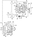
도 1은 본 발명의 실시형태의 Sn 합금 도금 장치를 도시하는 개요도이다.
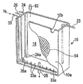
도 2는 애노드조를 도시하는 사시도이다.
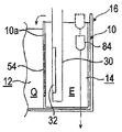
도 3은 애노드 내의 애노드액을 오버플로시키는 다른 예의 주요부를 도시하는 단면도이다.
도 4는 애노드 내의 애노드액을 오버플로시키는 또 다른 예의 주요부를 도시하는 사시도이다.
도 5는 도 1에 도시된 기판 홀더의 개략을 도시하는 사시도이다.
도 6은 도 1에 도시된 기판 홀더의 평면도이다.
도 7은 도 1에 도시된 기판 홀더의 우측면도이다.
도 8은 도 7의 A부 확대도이다.
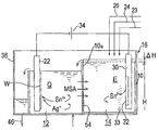
도 9는 Sn 합금 도금 장치로 도금을 행하고 있을 때의 상태를 도시하는 주요부 확대도이다.
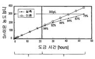
도 10은 전해량으로부터 환산되는 이론상의 애노드실 내의 애노드액의 Sn 이온 농도와, 실제로 측정한 Sn 이온 농도를 비교하여 나타내는 그래프이다.
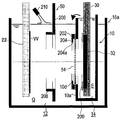
도 11은 다른 도금조를 도시하는 개요도이다.
도 12는 본 발명의 다른 실시형태의 Sn 합금 도금 장치를 도시하는 개요도이다.
도 13은 본 발명의 또 다른 실시형태의 Sn 합금 도금 장치를 도시하는 개요도이다.
도 14는 본 발명의 또 다른 실시형태의 Sn 합금 도금 장치를 도시하는 개요도이다.
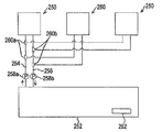
도 15는 본 발명의 또 다른 실시형태의 Sn 합금 도금 장치를 도시하는 개요도이다.1 is a schematic diagram showing a Sn alloy plating apparatus according to an embodiment of the present invention.
2 is a perspective view showing an anode tank.
3 is a cross-sectional view showing a main part of another example of overflowing the anode liquid in the anode.
4 is a perspective view showing a main part of another example of overflowing the anode liquid in the anode.
5 is a perspective view schematically showing the substrate holder shown in Fig.
Figure 6 is a top view of the substrate holder shown in Figure 1;
7 is a right side view of the substrate holder shown in Fig.
8 is an enlarged view of part A of Fig.
Fig. 9 is an enlarged view of a main part showing a state in which plating is performed by a Sn alloy plating apparatus.
10 is a graph showing the comparison between the Sn ion concentration of the anode liquid in the theoretical anode chamber converted from the electrolytic amount and the actually measured Sn ion concentration.
11 is a schematic view showing another plating bath.
12 is a schematic diagram showing a Sn alloy plating apparatus according to another embodiment of the present invention.
13 is a schematic view showing a Sn alloy plating apparatus according to still another embodiment of the present invention.
14 is a schematic view showing a Sn alloy plating apparatus according to still another embodiment of the present invention.
15 is a schematic diagram showing a Sn alloy plating apparatus according to still another embodiment of the present invention.
이하, 본 발명의 실시형태에 대해서 도면을 참조하여 설명한다. 이하의 각 예에서 동일 또는 상당하는 부재에는 동일한 부호를 붙이고, 중복된 설명을 생략한다.DESCRIPTION OF THE PREFERRED EMBODIMENTS Hereinafter, embodiments of the present invention will be described with reference to the drawings. In each of the following examples, the same or equivalent members are denoted by the same reference numerals, and redundant description is omitted.
이하의 예에서는, Sn(주석)보다 귀한 금속으로서 Ag(은)을 사용하여, 기판의 표면에 Sn-Ag 합금으로 이루어진 도금막을 형성하도록 하고 있다. 그리고, 2가의 Sn 이온과 착체를 형성하는 산으로서 메탄술폰산을 사용한다. 이 때문에, 도금액으로서, 도금액 중의 Sn 이온(Sn2 +)으로서 메탄술폰산주석을, Ag 이온(Ag+)으로서 메탄술폰산은을 포함한 Sn-Ag 합금 도금액을 이용하고 있다. Ag 이온(Ag+)으로서, 알킬술폰산은을 사용해도 좋다.In the following example, Ag (silver) is used as a precious metal rather than Sn (tin) to form a plated film made of Sn-Ag alloy on the surface of the substrate. Methanesulfonic acid is used as an acid to form a complex with a divalent Sn ion. Therefore, Sn-Ag alloy plating solution containing tin methanesulfonate as Sn ion (Sn 2 + ) and methanesulfonic acid silver as Ag ion (Ag + ) in the plating solution is used as the plating solution. As Ag ion (Ag + ), alkylsulfonic acid silver may be used.
도 1은, 본 발명의 실시형태의 Sn 합금 도금 장치를 도시하는 개요도이다. 도 1에 도시하는 바와 같이, 이 Sn 합금 도금 장치는, 박스형의 애노드조(10)를 내부에 배치함으로써, 내부가 캐소드실(12)과 애노드조(10)의 내부의 애노드실(14)로 구획된 도금조(16)를 구비하고 있다.1 is a schematic diagram showing a Sn alloy plating apparatus according to an embodiment of the present invention. 1, this Sn alloy plating apparatus has a box-
캐소드실(12)은, 하기의 오버플로조(36)를 통해서, 도금액 공급원(18)으로부터 연장되는 도금액 공급 라인(20)에 접속되어 있고, 내부에 Sn-Ag 합금 도금액(이하, 단순히 도금액이라고 함)(Q)을 유지하도록 구성되어 있다. 캐소드실(12)의 내부의 정해진 위치에는, 기판 홀더(22)에 착탈 가능하게 유지되어 도금시에 캐소드가 되는 기판(W)이 도금액(Q)에 침지되어 배치된다.The
한편, 애노드실(14)에는, 애노드액 공급 라인(23), 전해액 공급 라인(24), 순수 공급 라인(26) 및 배액 라인(28)이 각각 접속되어 있고, 내부에 애노드액(E)을 유지하도록 구성되어 있다. 애노드실(14)의 내부의 정해진 위치에는, 애노드 홀더(30)에 유지된, Sn을 재질로 하는 가용성의 Sn 애노드(32)가 애노드액(E)에 침지되어 배치된다. 또한, 애노드실(14)의 바닥부에는, 애노드액(E) 중에 질소 가스를 공급하여 애노드액(E)을 버블링하는 N2 가스 공급 라인(33)이 배치되어 있다.An anode
이 예에서는, 애노드액(E)으로서, 2가의 Sn 이온과 착체를 형성하는 메탄술폰산 및 Sn 이온을 포함하고, Ag 이온을 포함하지 않는 액이 사용되고 있다. 애노드액(E) 중의 메탄술폰산 이온의 일부는, Sn 이온의 주위를 둘러싸고 2가의 Sn 이온과 착체를 형성하며, 다른 일부는, 유리산으로서 애노드액(E) 중에 존재한다. 한편, 본 명세서에서, 메탄술폰산 농도란, 별도의 언급이 없는 한, 유리산으로서의 산농도를 가리킨다. 애노드액(E)에 Ag 이온은 포함되어 있지 않기 때문에, 애노드액(E) 중에 Sn 애노드(32)를 침지시키더라도, Ag가 Sn 애노드(32)와 반응하여 Sn 애노드(32)의 표면에 치환 석출되지는 않는다. 또, 전해액 공급 라인(24)을 통해서 애노드실(14)에 공급되는 전해액으로서, 메탄술폰산을 포함하는 수용액(메탄술폰산 수용액)이 사용되고 있다.In this example, as the anode liquid (E), a solution containing methane sulfonic acid and Sn ion which forms a complex with a divalent Sn ion and does not contain Ag ions is used. A part of the methanesulfonate ion in the anode liquid (E) surrounds the Sn ion and forms a complex with the divalent Sn ion, and the other part exists in the anode liquid (E) as the free acid. In the present specification, the methanesulfonic acid concentration refers to an acid concentration as a free acid, unless otherwise specified. Even if the
도금 처리시에 있어서, Sn 애노드(32)는, 도금 전원(34)의 정극에 접속되고, 기판(W)의 표면에 형성된 시드층 등의 도전층(도시 생략)은, 도금 전원(34)의 부극에 접속된다. 이에 의해, 도전층의 표면에 Sn-Ag 합금으로 이루어진 도금막이 형성된다. 이 도금막은, 예컨대 납 프리의 땜납 범프에 사용된다.The
도금조(16)에는, 캐소드실(12)의 상단을 오버플로한 도금액(Q)이 유입되는 오버플로조(36)가, 캐소드실(12)에 인접하여 마련되어 있다. 오버플로조(36)의 바닥부에는, 펌프(38), 열교환기(온도 조정기)(40), 필터(42) 및 유량계(44)를 개재한 도금액 순환 라인(46)의 일단이 접속되고, 이 도금액 순환 라인(46)의 타단은, 캐소드실(12)의 바닥부에 접속되어 있다. 또한, 오버플로조(36)의 꼭대기부에는, 도금액 공급원(18)으로부터 연장되는 도금액 공급 라인(20)이 접속되어 있다.An
캐소드실(12)의 내부에는, 이 내부에 배치되는 기판 홀더(22)와 Sn 애노드(32) 사이에 위치하여, 캐소드실(12) 내의 전위 분포를 조정하는 조정판(레귤레이션 플레이트)(50)이 배치되어 있다. 조정판(50)은, 이 예에서는, 재질로서, 유전체인 염화비닐을 이용하고 있으며, 전장의 확대를 충분히 제한할 수 있는 크기의 중앙 구멍(50a)을 갖고 있다. 조정판(50)의 하단은, 캐소드실(12)의 바닥판에 이르고 있다.An adjustment plate (regulation plate) 50, which is disposed between the
캐소드실(12)의 내부에는, 캐소드실(12) 내에 배치되는 기판 홀더(22)와 조정판(50) 사이에 위치하여, 수직 방향으로 연장되고, 기판(W)과 평행하게 왕복 운동하여, 기판 홀더(22)와 조정판(50) 사이의 도금액(Q)을 교반하는 교반구로서의 교반 패들(52)이 배치되어 있다. 도금 중에 캐소드실(12) 내의 도금액(Q)을 교반 패들(교반구)(52)로 교반함으로써, 충분한 금속 이온을 기판(W)의 표면에 균일하게 공급할 수 있다.And is disposed inside the
도금조(16)의 내부를 캐소드실(12)과 애노드실(14)로 구획하는 애노드조(10)의 캐소드실측의 격벽(10a)의 내부에는, 음이온 교환막(54)이 마련되고, 캐소드실(12)과 애노드실(14)은, 음이온 교환막(54)에 의해 격리되어 있다. 음이온 교환막(54)으로서, 예컨대 AGC 엔지니어링(주) 제조의 AAV가 사용되며, 메탄술폰산을 포함하는 수분자의 투과량에 맞춰, 임의의 매수의 음이온 교환막(54)이 격벽(10a)에 마련된다. 음이온 교환막(54)의 매수 및 배치는, 필요한 막면적 혹은 후술하는 수분자의 투과량에 맞춰 임의로 조정된다. 음이온 교환막(54)은, 캐소드실(12) 내의 도금액(Q)이 애노드실(14)로 이동하지 않도록, O링 등에 의해, 수밀적으로 격벽(10a)에 마련된다.An
격벽(10a) 및 음이온 교환막(54)은, Sn 애노드(32)와 기판(W) 사이에 위치하고 있다. 격벽(10a)은, 애노드실(14) 내의 애노드액(E)을 둑으로 차단하여, 이 격벽(10a)의 상단을 오버플로한 애노드액(E)이 캐소드실(12) 내로 유입되는 월류 둑으로서의 역할을 한다. 즉, 애노드실(14) 내에는, 격벽(월류 둑)(10a)에 의해 차단되어, 정해진 액면 레벨(H)(도 9 참조)의 애노드액(E)이 유지되며, 이 액면 레벨(H)을 초과하면, 이 초과된 양의 애노드액(E)이, 격벽(10a)의 상단을 오버플로하여, 애노드실(14) 내로 유입되도록 되어 있다.The
도금액 순환 라인(46)에는, 유량계(44)의 하류에 위치하여, 내부에 음이온 교환막(60)을 마련한 투석조(62)에 도금액(Q)을 공급하는 도금액 공급관(64)이 접속되고, 투석조(62)로부터 연장되는 도금액 배출관(66)은, 오버플로조(36)의 정부(頂部)에 접속되어 있다. 이 도금액 공급관(64)과 도금액 배출관(66)은, 도금액 순환 라인(46)에 접속되고, 상기 도금액 순환 라인(46)으로부터 도금액(Q)의 일부를 뽑아내어 순환시키는 도금액 투석 라인(68)을 구성하고 있다. 투석조(62)에는, 이 내부에 순수를 공급하는 순수 공급 라인(70)과, 내부의 순수를 외부로 배출하는 순수 배출 라인(72)이 각각 접속되어 있다.The plating
도금액 투석 라인(68) 내를 흐르는 도금액(Q)은, 투석조(62) 내에 공급되고, 음이온 교환막(60)을 이용한 투석에 의해, 유리산으로서의 메탄술폰산의 적어도 일부가 제거된 후, 오버플로조(36)로 되돌아간다. 이 투석에 의해 도금액(Q)으로부터 제거된 메탄술폰산은, 순수 공급 라인(70)을 통해서 투석조(62) 내에 공급되는 순수로 확산되어, 순수 배출 라인(72)으로부터 외부로 배출된다.The plating liquid Q flowing in the plating
음이온 교환막(60)으로서, 예컨대 AGC 엔지니어링(주) 제조의 DSV가 사용된다. 도금액의 투석량(메탄술폰산의 제거량)에 맞춰서, 임의의 매수의 음이온 교환막(60)이 투석조(62)에 마련된다.As the
한편, 이 예에서는, 확산 투석법을 이용한 투석조(62)를 이용하여 도금액(Q) 중의 유리산으로서의 메탄술폰산의 적어도 일부를 제거하고 있지만, 전기 투석법이나 이온 교환 수지법을 이용한 유리산 제거조를 이용하여 도금액(Q) 중의 유리산으로서의 메탄술폰산의 적어도 일부를 제거해도 좋다.On the other hand, in this example, at least a part of the methanesulfonic acid as the free acid in the plating liquid Q is removed by using the
도금액 순환 라인(46)에는, 상기 도금액 순환 라인(46) 내를 흐르는 도금액(Q)의 Sn 이온 농도를 측정하는 Sn 이온 농도 측정기(74)와, 상기 도금액 순환 라인(46) 내를 흐르는 도금액(Q)의 메탄술폰산 농도를 측정하는 메탄술폰산 농도 측정기(76)가 마련된다. Sn 이온 농도 측정기(74) 및 메탄술폰산 농도 측정기(76)로부터의 출력(즉, 농도 측정치)은, 도금액 공급원(18) 및 제어부(80)에 각각 입력된다.The plating
도 2는, 애노드조(10)를 도시하는 사시도이다. 도 2에 도시하는 바와 같이, 월류 둑으로서의 역할을 하는 격벽(10a)의 상단의 한방향으로 치우친 위치에는, 애노드실(14)을 오버플로한 애노드액(E)의 출구가 되는 월류용 노치(10b)가 마련되어 있다. 이 월류용 노치(10b)의 하단의 위치에 의해, 애노드실(14) 내에 유지되는 애노드액(E)의 액면 레벨(H)(도 9 참조)이 결정된다.2 is a perspective view showing the
전해액 공급 라인(24)은, 애노드조(10)의 측부를 따라서 하측으로 연장되어 있다. 전해액 공급 라인(24)의 하단에는, 전해액(메탄술폰산 수용액)을 애노드실(14)에 공급하는 전해액 공급구(24a)가 형성되어 있다. 이 전해액 공급구(24a)는, 애노드조(10)의 바닥부에 도달하여 수평 방향으로 개구되어 있다. 순수 공급 라인(26)도, 애노드조(10)의 측부를 따라서 하측으로 연장되어 있다. 순수 공급 라인(26)의 하단에는, 순수를 애노드실(14)에 공급하는 순수 공급구(26a)가 형성되어 있다. 이 순수 공급구(26a)는, 애노드조(10)의 바닥부에 도달하여 수평 방향으로 개구되어 있다. 한편, 전해액 공급구(24a) 및 순수 공급구(26a)를 하측을 향해 개구되도록 해도 좋다. 그리고, 이 전해액 공급구(24a) 및 순수 공급구(26a)와 격벽(10a)의 월류용 노치(10b)는, 애노드조(10)의 수평 투영면에서, 서로 대각선형으로 위치하도록 되어 있다. 이에 따라, 순수 공급 라인(26)을 통해서 순수가, 혹은 전해액 공급 라인(24)을 통해서 전해액이 애노드실(14)에 공급되었을 때, Sn 이온을 포함하는 애노드액(E)은, 공급된 순수 혹은 전해액으로 충분히 교반된 후, 월류용 노치(10b)를 오버플로하여 캐소드실(12)에 공급된다.The
N2 가스 공급 라인(33)은, 애노드조(10)의 측부를 따라서 하측으로 연장되어 애노드조(10)의 바닥부에 도달하여, 애노드조(10)의 길이 방향의 거의 전체 길이로 연장되어 있다. 그리고, N2 가스 공급 라인(33)에 형성한 분출구(33a)로부터 상측을 향해서 질소 가스를 방출함으로써 애노드액(E)을 버블링한다. 애노드실(14) 내의 애노드액(E)은, 질소 가스로 충분히 교반된다. 이에 의해, 애노드실(14) 내의 애노드액(E) 중에, Sn 이온 혹은 메탄술폰산이 균일하게 분포되는 것이 촉진되고, 애노드액(E) 중의 Sn 이온의 산화가 방지된다. 이 때문에, 질소 가스에 의한 애노드액(E)의 버블링은, 애노드실(14)의 바닥부로부터 행하는 것이 바람직하다.The N 2
한편, 순수 혹은 전해액을 애노드실(14)에 공급하기 직전에 질소 가스의 공급을 중지하여, 순수 혹은 전해액의 공급중에는 질소 가스에 의한 애노드액(E)의 버블링을 행하지 않는 것이 바람직하다. 이에 의해, 공급한 순수나 전해액에 의해 과도하게 희석되지 않고, Sn 이온이 충분히 확산된 애노드액(E)을 오버플로시켜 캐소드실(12)에 공급할 수 있다.On the other hand, it is preferable that the supply of the nitrogen gas is stopped immediately before supplying the pure water or the electrolytic solution to the
애노드실(14)의 상측에는, 애노드실(14) 내의 애노드액(E)의 액면 레벨을 검지함으로써, 애노드실(14) 내의 애노드액(E)의 증발에 의한 액량 감소를 검지하는 액면 검지 센서(82)가 마련되어 있다. 이에 따라, 애노드액(E)의 증발에 의한 액량 감소를 검지했을 때, 순수 공급 라인(26)으로부터 애노드실(14) 내의 애노드액(E)에 순수를 보충함으로써, 애노드실(14) 내의 애노드액(E)의 액면 레벨을 항상 일정하게 할 수 있다. 또한, 캐소드실(12)에 대한 Sn 이온의 공급량을 애노드실(14)에 대한 순수 혹은 전해액의 공급량으로 관리할 수 있다.A liquid level detecting sensor for detecting a decrease in liquid level due to the evaporation of the anode liquid (E) in the anode chamber (14) by detecting the liquid level of the anode liquid (E) in the anode chamber (14) (Not shown). The anode liquid E in the
한편, 애노드실(14) 내의 애노드액(E)의 캐소드실(12)에 대한 오버플로는, 기계적 수단으로 발생하게 할 수도 있다. 예컨대, 도 3에 도시하는 바와 같이, 애노드실(14) 내의 애노드액(E)에 플로우트(84)를 띄워 놓고, 플로우트(84)를 애노드액(E) 중에 가라앉힘으로써, 그 플로우트(84)의 체적분의 애노드액(E)을 캐소드실(12)에 오버플로시켜도 좋다. 이 경우, 순수나 전해액의 공급에 따른 물의 도입이 없기 때문에, 애노드액(E)이 희석되지 않고 애노드액(E)이 캐소드실(12)에 공급된다.On the other hand, the overflow of the anode liquid E in the
또한, 도 4에 도시하는 바와 같이, 월류 둑으로서의 역할을 하는 격벽(10a)의 상단에 마련된 직사각형 노치(10c)의 내부에, 가동 둑(86)을 상하 이동 가능하게 마련해도 좋다. 도 4에 도시된 예에서는, 가동 둑(86)을 하강시켜 그 높이만큼의 애노드액(E)을 캐소드실(12)에 공급한다. 이 경우도, 애노드액(E)이 희석되어 캐소드실(12)에 공급되는 것을 방지할 수 있다.4, the
시스템 전체의 Sn 이온이 부족할 때에는, 도금액(Q)에 Sn 이온을 보급할 필요가 있다. 이 Sn 이온을 보급하는 방법으로서, 고농도의 Sn 보급액을 도금액(Q)에 첨가하는 방법을 들 수 있지만, 고농도의 Sn 보급액은 일반적으로 고가이고, 비용 상승으로 이어진다. 따라서, 이 예에서는, 도금조(16)와는 별도로, Sn 이온을 보급하는 보조 전해조(100)를 설치하고 있다.When Sn ions in the entire system are insufficient, it is necessary to supply Sn ions to the plating liquid (Q). As a method of supplying the Sn ions, a method of adding a high-concentration Sn-replenishing solution to the plating solution (Q) can be mentioned, but the high-concentration Sn-replenishing solution is generally expensive and leads to an increase in cost. Therefore, in this example, an auxiliary
보조 전해조(100)의 내부에는, 박스형의 캐소드조(102)가 배치되어 있다. 보조 전해조(100)의 내부는, 애노드실(보조 애노드실)(104)과, 캐소드조(102)의 내부의 캐소드실(보조 캐소드실)(106)로 구획되어 있다. 그리고, 애노드실(104)과 캐소드실(106)을 구획하는 캐소드조(102)의 애노드실측의 격벽(102a)의 내부에는, 음이온 교환막(108)이 마련되어 있다. 보조 전해조(100)는, 음이온 교환막(108)에 의해 애노드실(104)과 캐소드실(106)로 격리되어 있다.Inside the auxiliary
애노드실(104)에는, Sn 이온과 메탄술폰산을 포함하며 Ag 이온을 포함하지 않는 애노드액(A)을 공급하는 애노드액 공급 라인(110)과, 메탄술폰산을 포함하는 수용액(메탄술폰산 수용액)으로 이루어진 전해액을 공급하는 전해액 공급 라인(112)이 접속되어 있다. 애노드실(104)의 내부에는, 애노드 홀더(116)로 유지한 Sn 애노드(보조 Sn 애노드)(118)가 애노드액(A)에 침지되어 배치된다. 또한, 애노드실(104)에는, Sn 이온 보급 라인(114)의 일단이 접속되고, Sn 이온 보급 라인(114)의 타단은, 도금조(16)의 오버플로조(36)의 상단에 접속되어 있다. Sn 이온 보급 라인(114)에는, 펌프(120)가 설치되어 있다.The
캐소드실(106)에는, 메탄술폰산을 포함하는 수용액(메탄술폰산 수용액)으로 이루어진 캐소드액(B)을 공급하는 캐소드액 공급 라인(122)과, 캐소드액(B)을 배출하는 배액 라인(124)이 접속되고, 캐소드실(106)의 내부에는, 캐소드 홀더(126)로 유지된, 예컨대 SUS로 이루어진 캐소드(보조 캐소드)(128)가 캐소드액(B)에 침지되어 배치된다. 전술한 격벽(102a) 및 음이온 교환막(108)은, Sn 애노드(118)와 캐소드(128) 사이에 위치하고 있다.The
이 보조 전해조(100)에서는, 우선, 애노드액 공급 라인(110)을 통해, 고농도(예컨대, 220 g/L∼350 g/L)의 Sn 이온과 메탄술폰산을 포함하고 Ag 이온을 포함하지 않는 애노드액(A)을 애노드실(104) 내에 공급하고, 이 애노드액(A) 중에 Sn 애노드(118)를 침지시켜 놓는다. 또한, 캐소드액 공급 라인(122)을 통해, 메탄술폰산 수용액으로 이루어진 캐소드액(B)을 캐소드실(106) 내에 공급하고, 이 캐소드액(B) 중에 캐소드(128)를 침지시켜 놓는다.In this auxiliary
이 상태로, 보조 전원(130)의 정극을 Sn 애노드(118)에, 부극을 캐소드(128)에 각각 접속하여 전해를 시작한다. 이와 같이 전해를 시작하면, Sn 애노드(118)로부터 Sn 이온이 용해하여 애노드액(A)의 Sn 이온 농도가 증가한다. 애노드실(104)과 캐소드실(106)은 음이온 교환막(108)으로 격리되어 있기 때문에, Sn 이온은 캐소드실(106) 내로 이동하지 않아, 캐소드(128)가 도금되지는 않는다. 또한, 애노드액(A)에는 Ag 이온이 포함되어 있지 않기 때문에, Sn 애노드(118)의 표면에 Ag가 치환 석출되지는 않는다. 애노드액(A)에 포함되는 Sn 이온은, 운전 시작전에는 애노드액 공급 라인(110)으로부터 공급되지만, 운전 시작후에는 Sn 애노드(118)로부터 용해됨으로써 공급된다.In this state, the positive electrode of the
그리고, 정해진 농도에 도달한 애노드액(A)은, 펌프(120)를 구동시킴으로써, Sn 이온 보급 라인(114)을 통해서, 도금조(16)의 오버플로조(36) 내에 공급된다. 애노드액(A)의 오버플로조(36)에 대한 공급에 의해, 애노드실(104) 내의 애노드액(A)의 액량이 감소하기 때문에, 그것을 보충하는 양의 전해액이 전해액 공급 라인(112)으로부터 애노드실(104)에 보급된다. 애노드액(A) 중의 Sn 이온 농도가 높은 쪽이, 시스템 전체로부터의 배액량을 억제할 수 있기 때문에 유리하다.The anode liquid A having reached the predetermined concentration is supplied into the
캐소드실(106)의 캐소드액(B)에 포함되는 메탄술폰산 이온은, 음이온 교환막(108)을 투과하여, 애노드실(104) 내로 이동한다. 이 때문에, 시간 경과와 함께, 캐소드실(106)의 캐소드액(B)의 도전도는 저하되어 간다. 따라서, 캐소드실(106)에 접속한 캐소드액 공급 라인(122)을 통해서, 캐소드실(106)에 캐소드액(B)을 보급한다. 보급한 만큼의 캐소드액(B)이 넘치지 않도록, 배액 라인(124)을 통해서, 캐소드실(106) 내의 캐소드액(B)을 외부로 배출한다.Methane sulfonic acid ions included in the cathode liquid B in the
기판 홀더(22)는, 도 5 내지 도 8에 도시하는 바와 같이, 직사각형 평판형의 제1 유지 부재(154)와, 이 제1 유지 부재(154)에 힌지(156)를 통해 개폐 가능하게 부착된 제2 유지 부재(158)를 갖고 있다. 다른 구성예로서, 제2 유지 부재(158)를 제1 유지 부재(154)에 대치한 위치에 배치하여, 이 제2 유지 부재(158)를 제1 유지 부재(154)를 향해서 전진시키고, 또한 제1 유지 부재(154)로부터 이격시킴으로써 제2 유지 부재(158)를 개폐하도록 해도 좋다.5 to 8, the
제1 유지 부재(154)는, 예컨대 염화비닐제이다. 제2 유지 부재(158)는, 베이스부(160)와, 링형의 시일 홀더(162)를 갖고 있다. 시일 홀더(162)는, 예컨대 염화비닐제이며, 하기 압박링(164)과의 슬립을 좋게 하고 있다. 시일 홀더(162)의 상부에는 환형의 기판측 시일 부재(166)(도 7 및 도 8 참조)가 내측으로 돌출되어 부착되어 있다. 이 기판측 시일 부재(166)는, 기판 홀더(22)가 기판(W)을 유지했을 때, 기판(W)의 표면 외측 둘레부에 압접하여 제2 유지 부재(158)와 기판(W)의 간극을 시일한다. 시일 홀더(162)의 제1 유지 부재(154)와 대향하는 면에는, 환형의 홀더측 시일 부재(168)(도 7 및 도 8 참조)가 부착되어 있다. 이 홀더측 시일 부재(168)는, 기판 홀더(22)가 기판(W)을 유지했을 때, 제1 유지 부재(154)에 압접하여 제1 유지 부재(154)와 제2 유지 부재(158)의 간극을 시일한다. 홀더측 시일 부재(168)는, 기판측 시일 부재(166)의 외측에 위치하고 있다.The
도 8에 도시하는 바와 같이, 기판측 시일 부재(166)는, 시일 홀더(162)와 제1 고정 링(170a) 사이에 끼워져 시일 홀더(162)에 부착되어 있다. 제1 고정 링(170a)은, 시일 홀더(162)에 볼트 등의 체결구(169a)를 통해 부착된다. 홀더측 시일 부재(168)는, 시일 홀더(162)와 제2 고정링(170b) 사이에 끼워져 시일 홀더(162)에 부착되어 있다. 제2 고정링(170b)은, 시일 홀더(162)에 볼트 등의 체결구(169b)를 통해 부착된다.The substrate
시일 홀더(162)의 외측 둘레부에는 단차부가 형성되어 있고, 이 단차부에는 압박링(164)이 스페이서(165)를 통해 회전 가능하게 장착되어 있다. 압박링(164)은, 시일 홀더(162)의 측면에 외측으로 돌출되도록 부착된 압박판(172)(도 6 참조)에 의해, 이탈 불가능하게 장착되어 있다. 이 압박링(164)은, 산이나 알칼리에 대하여 내식성이 우수하고, 충분한 강성을 갖는 재료로 구성된다. 예컨대, 압박링(164)은 티탄으로 구성된다. 스페이서(165)는, 압박링(164)이 원활하게 회전할 수 있도록, 마찰계수가 낮은 재료, 예컨대 PTFE로 구성되어 있다.A stepped portion is formed on the outer periphery of the
압박링(164)의 외측에는, 복수의 클램퍼(174)가 압박링(164)의 원둘레 방향을 따라서 등간격으로 배치되어 있다. 이들 클램퍼(174)는 제1 유지 부재(154)에 고정되어 있다. 각 클램퍼(174)는, 내측으로 돌출된 돌출부를 갖는 역 L자형의 형상을 갖고 있다. 압박링(164)의 외측 둘레면에는, 외측으로 돌출된 복수의 돌기부(164b)가 마련되어 있다. 이들 돌기부(164b)는, 클램퍼(174)의 위치에 대응하는 위치에 배치되어 있다. 클램퍼(174)의 내측 돌출부의 하면 및 압박링(164)의 돌기부(164b)의 상면은, 압박링(164)의 회전 방향을 따라서 서로 역방향으로 경사진 테이퍼면으로 되어 있다. 압박링(164)의 원둘레 방향을 따른 복수 개소(예컨대, 3개소)에는, 상측으로 돌출된 볼록부(164a)가 마련되어 있다. 이에 따라, 회전핀(도시 생략)을 회전시켜 볼록부(164a)를 옆으로부터 밀어 돌림으로써, 압박링(164)을 회전시킬 수 있다.A plurality of
제2 유지 부재(158)를 개방한 상태에서, 제1 유지 부재(154)의 중앙부에 기판(W)이 삽입되어, 힌지(156)를 통해 제2 유지 부재(158)가 폐쇄된다. 압박링(164)을 시계 방향으로 회전시켜, 압박링(164)의 돌기부(164b)를 클램퍼(174)의 내측 돌출부의 내부로 미끄러져 들어가게 함으로써, 압박링(164)과 클램퍼(174)에 각각 형성한 테이퍼면을 통해, 제1 유지 부재(154)와 제2 유지 부재(158)를 서로 체결하여 제2 유지 부재(158)를 고정한다. 또한, 압박링(164)을 반시계 방향으로 회전시켜 압박링(164)의 돌기부(164b)를 클램퍼(174)로부터 해제함으로써, 제2 유지 부재(158)의 고정을 풀게 되어 있다.The substrate W is inserted into the center of the first holding
제2 유지 부재(158)를 고정했을 때, 기판측 시일 부재(166)의 하측 돌출부는 기판(W)의 표면 외측 둘레부에 압접된다. 기판측 시일 부재(166)는 균일하게 기판(W)에 압박되고, 이에 의해 기판(W)의 표면 외측 둘레부와 제2 유지 부재(158)의 간극을 시일한다. 마찬가지로, 제2 유지 부재(158)를 고정했을 때, 홀더측 시일 부재(168)의 하측 돌출부는 제1 유지 부재(154)의 표면에 압접된다. 홀더측 시일 부재(168)는 균일하게 제1 유지 부재(154)에 압박되고, 이에 의해 제1 유지 부재(154)와 제2 유지 부재(158) 사이의 간극을 시일한다.When the second holding
제1 유지 부재(154)의 단부에는, 한쌍의 대략 T자형의 홀더 행거(190)가 마련되어 있다. 제1 유지 부재(154)의 상면에는, 기판(W)의 크기와 거의 같은 링형의 돌조부(182)가 형성되어 있다. 이 돌조부(182)는, 기판(W)의 둘레 가장자리부에 접촉하여 상기 기판(W)을 지지하는 환형의 지지면(180)을 갖고 있다. 이 돌조부(182)의 원둘레 방향을 따른 정해진 위치에 오목부(184)가 마련되어 있다.At the end of the first holding
도 6에 도시하는 바와 같이, 오목부(184) 내에는 복수(도시에서는, 12개)의 도전체(전기 접점)(186)가 각각 배치되어 있다. 이들 도전체(186)는, 홀더 행거(190)에 마련된 접속 단자(도시 생략)로부터 연장되는 복수의 배선에 각각 접속되어 있다. 제1 유지 부재(154)의 지지면(180) 상에 기판(W)을 배치했을 때, 이 도전체(186)의 단부가 도 8에 도시된 전기 접점(188)의 하부에 탄성적으로 접촉하도록 되어 있다.As shown in Fig. 6, a plurality of (in this example, twelve) conductors (electrical contacts) 186 are disposed in the
도전체(186)에 전기적으로 접속되는 전기 접점(188)은, 볼트 등의 체결구(189)에 의해 제2 유지 부재(158)의 시일 홀더(162)에 고착되어 있다. 이 전기 접점(188)은, 판스프링 형상으로 형성되어 있다. 전기 접점(188)은, 기판측 시일 부재(166)의 외측에 위치된, 내측에 판스프링형으로 돌출된 접점부를 갖고 있다. 전기 접점(188)은 이 접점부에서, 그 탄성력에 의한 스프링성을 갖고 용이하게 굴곡하도록 되어 있다. 제1 유지 부재(154)와 제2 유지 부재(158)로 기판(W)을 유지했을 때, 전기 접점(188)의 접점부가, 제1 유지 부재(154)의 지지면(180) 상에 지지된 기판(W)의 외측 둘레면에 탄성적으로 접촉하도록 구성되어 있다.The
제2 유지 부재(158)의 개폐는, 도시하지 않은 에어실린더와 제2 유지 부재(158)의 자체 중량에 의해 행해진다. 즉, 제1 유지 부재(154)에는 통과 구멍(154a)이 형성되고, 에어실린더(도시 생략)의 피스톤 로드에 의해, 통과 구멍(154a)을 통하여 제2 유지 부재(158)의 시일 홀더(162)를 상측으로 밀어 올림으로써 제2 유지 부재(158)를 개방하고, 피스톤 로드를 수축시킴으로써, 제2 유지 부재(158)를 그 자체 중량으로 폐쇄하도록 되어 있다.The opening and closing of the second holding
다음에, 이 실시형태의 도금 장치의 동작에 대해서 설명한다. 펌프(38)를 구동시켜, 도금액 순환 라인(46)을 통해서, 캐소드실(12) 내의 도금액(Q)을 순환시켜 교반한다. 이 상태로, 기판 홀더(22)로 유지한 기판(W)을 캐소드실(12) 내의 도금액(Q)에 침지시키면서 정해진 위치에 배치한다. 한편, 애노드실(14)의 내부는 초기의 애노드액(E)으로 채워, Sn 애노드(32)를 애노드액(E)에 침지시켜 놓는다.Next, the operation of the plating apparatus of this embodiment will be described. The
이 상태로, Sn 애노드(32)를 도금 전원(34)의 정극에, 기판(W)의 표면에 형성된 시드층 등의 도전층을 도금 전원(34)의 부극에, 각각 접속하여, 기판(W)의 표면에 도금 처리를 시작한다. 이 도금시에, 필요에 따라서, 교반 패들(교반구)(52)을 기판(W)과 평행하게 왕복 운동시켜, 캐소드실(12) 내의 도금액(Q)을 교반한다. 동시에, N2 가스 공급 라인(33)을 통해서, 애노드실(14) 내의 애노드액(E)을 질소 가스로 버블링한다.The
이와 같이, 도금 처리를 행하면, 도 9에 도시하는 바와 같이, Sn 애노드(32)로부터 애노드실(14) 내의 애노드액(E) 중에 Sn 이온이 용출된다. Sn 이온의 용출은, 도금 처리를 할 때마다 생기기 때문에, 애노드실(14) 내의 애노드액(E)의 Sn 이온 농도는 상승해 간다. 또한, 전해액 공급 라인(24)으로부터 전해액, 혹은 순수 공급 라인(26)으로부터 순수를 애노드실(14) 내에 공급하면, 애노드실(14) 내의 애노드액(E)이 증가한다. 애노드실(14) 내의 애노드액(E)의 액면 레벨이 정해진 액면 레벨(H)을 초과하여 ΔH만큼 상승하려 하면, 이 액면 레벨의 상승량 ΔH에 부합하는 양의 애노드액(E)은, 애노드실(14)의 격벽(10a)에 마련된 월류용 노치(10b)(도 2 참조)를 오버플로하여, 캐소드실(12) 내로 유입된다. 이에 따라, 애노드실(14) 내의 Sn 이온의 일부는 캐소드실(12) 내에 공급되어, 기판(W)에 대한 도금에 의해 소비된 Sn 이온을 보충할 수 있다. 이와 같이, 애노드액(E)이 도금액(Q)에 공급되면, 도금액(Q)의 양이 증가하기 때문에, 캐소드실(12) 내에 공급된 애노드액(E)에 부합하는 양의 도금액(Q)은 미리 배출된다.As described above, when plating is performed, Sn ions are eluted from the
한편, Sn 애노드(32)와 캐소드로서의 기판(W)의 사이에 전계를 형성하면, 캐소드실(12) 내의 메탄술폰산은, 수분자와 함께, 음이온 교환막(54)을 투과하여 애노드실(14) 내로 유입된다. 이에 의해서도, 애노드실(14) 내의 애노드액(E)이 증가하고, 정해진 액면 레벨(H)을 상회하는 만큼의 애노드액(E)은 격벽(10a)을 오버플로하여, 캐소드실(12) 내로 유입된다. 이렇게 하여, 애노드실(14) 내의 Sn 이온을 캐소드실(12)에 공급할 수 있다.On the other hand, when an electric field is formed between the
여기서, 발명자들은, 애노드실(14) 내의 유리산으로서의 메탄술폰산의 농도가, Sn 애노드로부터 용해된 Sn 이온을 안정화시키기 위해 중요하다는 것을 실험을 통해 확인했다. 실험에서, 메탄술폰산 농도가 100 g/L이 되도록, 애노드실에 메탄술폰산 수용액으로 이루어진 애노드액을 넣고, 전해를 시작했다. 이 경우, 전해를 계속해 가면, 애노드실 내의 애노드액에 탁함이 생겼다. 이것은, 애노드액 중에서 Sn 이온이 2가의 이온으로서 안정적으로 존재할 수 없어, 금속 Sn으로서 석출되거나, 4가의 Sn 이온이 생기고 있는 것을 나타내고 있다.Here, the inventors have experimentally confirmed that the concentration of methanesulfonic acid as free acid in the
이에 비해, 메탄술폰산 농도를 140 g/L로 하여 전해를 시작한 경우에는, 전해를 계속하더라도 애노드실 내의 애노드액에 탁함이 없고, 애노드액 중의 Sn 이온 농도는 Sn이 2가로 용해한 경우의 계산치에 일치했다. 즉, 메탄술폰산 이온이 충분히 존재하기 때문에, 2가의 Sn 이온은, 그 둘레가 메탄술폰산 이온으로 둘러싸여 착체를 형성하여 안정적으로 존재하고 있는 것을 나타내고 있다. 그 때문에, 애노드액의 메탄술폰산 농도는, Sn 이온이 2가의 이온으로 안정적으로 존재하기에 적합한 농도로 하는 것이 필요하다는 것을 알 수 있다.On the other hand, when electrolysis was started at a concentration of methanesulfonic acid of 140 g / L, even if the electrolysis was continued, there was no turbidity in the anode liquid in the anode chamber, and the Sn ion concentration in the anode liquid coincided with the calculated value did. That is, since methanesulfonic acid ions are sufficiently present, divalent Sn ions are surrounded by methanesulfonic acid ions to form complexes and stably exist. Therefore, it can be understood that the concentration of methane sulfonic acid in the anode liquid is required to be a concentration suitable for stably presenting Sn ions as divalent ions.
전술한 바와 같이, 순수 공급 라인(26)으로부터 애노드실(14) 내에 순수를 공급함으로써, 애노드실(14) 내의 애노드액(E)을 캐소드실(12)에 오버플로시켜, Sn 이온을 캐소드실(12)에 공급할 수 있다. 이 예에서는, 전해액(메탄술폰산 수용액)을 애노드실(14)에 공급하는 전해액 공급 라인(24)을 형성하고 있다. 이것은, 이하의 이유에 따른 것이다.As described above, pure water is supplied into the
순수 공급 라인(26)으로부터 애노드실(14)에 순수를 공급하여 애노드실(14) 내의 애노드액(E)을 오버플로시키면, 애노드실(14) 내의 메탄술폰산이 캐소드실(12) 내로 흘러, 애노드실(14) 내의 애노드액(E)의 메탄술폰산 농도가 저하된다. 또한, 캐소드실(12) 내의 메탄술폰산은, Sn 애노드(32)와 캐소드로서의 기판(W) 사이에 전계를 형성함으로써, 음이온 교환막(54)을 투과하여, 캐소드실(12)로부터 애노드실(14)로 이동한다. 그 메탄술폰산의 운반율은, 그 조건에 따라 달라지지만, 100%는 아니며, 손실이 있기 때문에 50% 내지 90%가 되는 경우가 있다. 이 경우, 애노드실(14)에서는, Sn 애노드(32)로부터 용해되는 Sn 이온에 대한, 음이온 교환막(54)을 투과하여 애노드실(14)로 이동하는 메탄술폰산의 몰농도의 비가 1:2로부터 어긋나게 된다. 결과적으로, 애노드실(14) 내의 애노드액(E) 중의 메탄술폰산 농도는 낮아져 버린다. 이에 따라, 전술한 바와 같이, 애노드실(14) 내의 Sn 이온이 불안정화될 우려가 있다.When pure water is supplied from the pure
그 때문에, 애노드실(14) 내의 애노드액(E)의 메탄술폰산 농도가 허용치보다 낮아지지 않도록, 전해액 공급 라인(24)으로부터 메탄술폰산을 포함하는 전해액을 애노드실(14)에 공급하는 것이 필요하다.Therefore, it is necessary to supply the electrolytic solution containing methanesulfonic acid from the electrolytic
도금 장치의 효율적인 운전을 위해서는, 애노드실(14) 내의 애노드액(E)의 Sn 이온 농도가 가능한 한 높은 상태로, 애노드액(E)을 오버플로에 의해 캐소드실(12)에 공급하는 것이 바람직하다. 이것은, Sn 이온 농도가 낮은 상태로 애노드액(E)을 캐소드실(12)에 공급하면, 어떤 양의 Sn 이온을 캐소드실(12)에 공급하기 위한 애노드실(14)로부터의 애노드액(E)의 공급량(오버플로량)이 많아지고, 그만큼, 캐소드실(12)을 포함하는 순환계로부터 폐액하는 도금액(Q)의 액량이 증가하여, 경제적이지 않기 때문이다.For efficient operation of the plating apparatus, it is preferable to supply the anode liquid E to the
구체적으로는, 애노드실(14)의 애노드액(E) 중의 Sn 이온 농도를, 일반적으로는, 80 g/L∼500 g/L, 바람직하게는 200 g/L∼400 g/L, 더욱 바람직하게는 220 g/L∼350 g/L의 범위로 관리한다. 애노드액(E) 중의 Sn 이온 농도는, 운전 시작전에 애노드실(14)에 새롭게 투입한 애노드액(E) 중의 Sn 이온 농도와, 운전 시작후의 Sn 애노드(32)에서의 전해량으로부터 환산된 Sn 이온 농도로부터 구해진다. 이 애노드액(E)의 Sn 이온 농도는, 도금조 전체의 Sn 이온 농도를 관리하기 위해 매우 중요하다.Specifically, the Sn ion concentration in the anode liquid (E) of the
Sn-Ag 도금액(Q) 중의 Sn 이온 농도는, 통상 50 g/L∼80 g/L이다. 캐소드실(12) 중의 Sn 이온 농도의 감소분을 애노드실(14)의 Sn 이온을 포함하는 애노드액(E)으로 보충하고자 하는 경우, 애노드실(14)의 애노드액(E)의 Sn 이온 농도가 높으면 높을수록 캐소드실(12)에 보급하는 애노드액(E)의 체적이 적어도 된다. 통상, 캐소드실(12)의 도금액(Q)의 양은 증발 등으로 감소한다. 그 감량분 이상으로 애노드실(14)의 애노드액(E)을 보급한 경우, 감량분 이상의 과잉 액량은, 최종적으로 캐소드실(12)의 도금액(Q)으로부터 폐액할 필요가 생긴다. 단, 애노드액(E)의 Sn 이온의 농도는, 메탄술폰산주석의 포화 농도 이상까지는 높일 수 없다. 또한, Sn 이온이 안정적으로 존재하기 위해서는, 애노드액(E)의 Sn 이온의 농도를 포화 농도 이하로 해 놓을 필요가 있다.The Sn ion concentration in the Sn-Ag plating liquid (Q) is usually 50 g / L to 80 g / L. When the decrease in the Sn ion concentration in the
순수 공급 라인(26)은, 애노드실(14) 내의 수분 증발분을 보충하는 것에 사용될 뿐만 아니라, 애노드실(14) 내의 애노드액(E)의 메탄술폰산 농도가 충분히 높은 경우에, 애노드실(14) 내의 애노드액(E)을 오버플로시켜 Sn 이온을 캐소드실(12) 내에 공급하는 것에 사용된다. 또한, 순수 공급 라인(26)은, 애노드실(14) 내에 순수를 공급함으로써, 애노드실(14) 내의 성분 농도를 조정하는 경우에 사용된다.The
다음으로, 도 1에 도시된 Sn 합금 도금 장치의 운전예를 설명한다.Next, an operation example of the Sn alloy plating apparatus shown in Fig. 1 will be described.
Sn 합금 도금 장치의 운전을 시작하기 전에, 우선, 애노드액 공급 라인(23)을 통해서 고농도의 Sn 이온(예컨대, 220 g/L∼350 g/L)과 메탄술폰산을 포함하는 애노드액(E)을 애노드실(14)에 공급하여, 애노드실(14)을 애노드액(E)으로 채워 놓는다. 이것은, 전술한 바와 같이, Sn 이온 농도가 높은 상태로, 애노드실(14)의 애노드액(E)을 캐소드실(12)에 보급함으로써, 도금액(Q)을 폐액하는 양을 줄일 수 있기 때문에 유리하며, 애노드액(E)의 Sn 이온 농도가 저농도의 상태로 운전을 시작하면, 애노드액(E)의 Sn 이온 농도가 고농도가 될 때까지 대기할 필요가 있어, 불리하기 때문이다.(E) containing methane sulfonic acid and a high concentration of Sn ions (for example, 220 g / L to 350 g / L) through the anode
전술한 바와 같이, 펌프(38)를 구동시켜, 도금액 순환 라인(46)을 통해서, 캐소드실(12) 내의 도금액(Q)을 순환시켜 교반한 상태로, 기판 홀더(22)로 유지한 기판(W)을 캐소드실(12) 내의 도금액(Q)에 침지시키면서 정해진 위치에 배치한다.As described above, the
이 상태로, Sn 애노드(32)를 도금 전원(34)의 정극에, 기판(W)의 표면에 형성된 시드층 등의 도전층을 도금 전원(34)의 부극에 각각 접속하여, 기판(W)의 표면에 도금 처리를 시작한다. 이 도금시에, 필요에 따라서, 교반 패들(교반구)(52)을 기판(W)과 평행하게 왕복 운동시켜, 캐소드실(12) 내의 도금액(Q)을 교반한다. 동시에, N2 가스 공급 라인(33)을 통해서 애노드실(14) 내의 애노드액(E)에 질소 가스를 공급하여 애노드액(E)을 버블링한다.The
이와 같이 하여 도금을 행하면서, 도금액(Q)의 Sn 이온 농도를 Sn 이온 농도 측정기(74)로 측정하여, 그 측정 결과를 신호(측정치)로서 제어부(80)에 보낸다. 제어부(80)는, 이 예에서는, 애노드실(14)의 애노드액(E)의 메탄술폰산 농도를 추정하고, 이 추정치에 기초하여, 전해액 공급 라인(24)으로부터 전해액을 애노드실(14)에 공급하거나, 순수 공급 라인(26)으로부터 순수를 공급하는 어느 한쪽, 혹은 그 조합을 결정한다. 즉, 애노드액(E)의 유리산으로서의 메탄술폰산 농도가 하한치를 하회하지 않도록, 정해진 값을 하회했을 때에는 전해액 공급 라인(24)으로부터 메탄술폰산을 포함하는 전해액을 애노드실(14)에 공급한다. 애노드실(14)의 메탄술폰산의 농도가 충분히 높은 시점에서 캐소드실(12)에 Sn 이온을 보급할 필요가 있을 때에는, 순수 공급 라인(26)으로부터 순수를 애노드실(14)에 공급한다. 애노드실(14)의 애노드액(E)은, 캐소드실(12)에 오버플로하여, Sn 이온이 캐소드실(12)의 도금액(Q)에 공급된다.While performing plating in this manner, the Sn ion concentration of the plating liquid Q is measured by the Sn ion
애노드실(14) 내의 애노드액(E)의 유리산으로서의 메탄술폰산 농도는, 30 g/L 이상이 되도록 컨트롤되고, 이에 따라, 예컨대 220 g/L∼350 g/L의 고농도의 Sn 이온이 2가의 이온으로서 안정적으로 존재할 수 있다. 애노드액(E)의 메탄술폰산 농도가 높으면, 애노드액(E)의 공급에 의해 캐소드실(12)의 도금액(Q)의 메탄술폰산 농도도 높아지게 되어, 후술하는 바와 같이, 도금에서의 막두께 균일성이 나빠진다. 이 때문에, 도금액(Q)의 메탄술폰산 농도는, 실제 장치의 운전 상황을 고려하여, 필요 이상으로 높아지지 않도록 미리 정해진다.The concentration of methanesulfonic acid as the free acid of the anode liquid E in the
캐소드실(12) 내의 도금액(Q) 중의 유리산으로서의 메탄술폰산 농도는, Sn 애노드(32)에서의 전해량 및 전류 효율, 애노드액(E)의 오버플로에 의한 공급량, 도금액 순환 라인(46)으로부터의 배액(드레인아웃)량, 음이온 교환막(54)의 메탄술폰산의 투과율에 따라 변동한다. 캐소드실(12)의 도금액(Q)의 메탄술폰산 농도가 약 250 g/L을 초과하면, 기판 도금에서의 막두께 균일성이 나빠지는 경향이 있다. 따라서, 캐소드실(12) 내의 도금액(Q)의 메탄술폰산 농도가 상한치를 상회한 것을, 메탄술폰산 농도 측정기(76)에 의해 검지했을 때, 도금액(Q)으로부터 메탄술폰산을 제거하는 투석조(62)를 갖는 도금액 투석 라인(68) 내에 도금액(Q)을 흘리고, 이 메탄술폰산을 제거한 도금액(Q)을 오버플로조(36)로 되돌린다. 이에 의해, 도금에 사용되는 도금액(Q)의 메탄술폰산 농도를, 예컨대 60 g/L∼250 g/L의 바람직한 범위내로, 더욱 바람직하게는 90 g/L∼150 g/L의 범위내로 조정할 수 있다.The concentration of methane sulfonic acid as the free acid in the plating solution Q in the
Sn 합금 도금 장치의 운전중에서의 애노드액(E) 중의 유리산으로서의 메탄술폰산 농도는, 애노드실(14) 내의 애노드액(E)의 메탄술폰산 농도의 추정치에 기초하여 관리해도 좋다. 이 메탄술폰산 농도의 추정치는, 초기의 애노드액(E)의 메탄술폰산 농도, Sn 애노드(32)에서의 전해량 및 전류 효율, 전해액 공급 라인(24)으로부터의 전해액의 공급량, 순수 공급 라인(26)으로부터의 순수의 공급량 및 음이온 교환막(54)을 투과하여 캐소드실(12)로부터 애노드실(14)로 이동해 오는 메탄술폰산의 투과율로부터 이론적 혹은 실험적으로 구해진다. 애노드실(14) 내의 Sn 이온과 메탄술폰산의 농도는, 도금 처리의 전해량에 따른 Sn 이온 용해량 곡선 및 산의 음이온 교환막 투과율로부터 추측할 수 있다.The concentration of methanesulfonic acid as the free acid in the anode liquid E during the operation of the Sn alloy plating apparatus may be controlled based on the estimated value of the methanesulfonic acid concentration of the anode liquid E in the
전술한 바와 같이, Sn 합금 도금 장치의 운전을 시작하기 전에, 우선 애노드실(14)에는 고농도의 Sn 이온(예컨대, 220 g/L∼350 g/L)과 메탄술폰산을 포함하는 애노드액(E)이 유지된다. 그리고, Sn 합금 도금 장치의 운전중에는, Sn 애노드의 전해량 및 전해 효율 등으로부터 추정되는 애노드실(14) 내의 애노드액(E)의 Sn 이온 농도가 정해진 임계치(예컨대, 300 g/L)에 도달하면, 전해액 공급 라인(24)으로부터 전해액을 애노드실(14)에 공급하고 애노드액(E)을 오버플로시켜 캐소드실(12)에 Sn 이온을 보급한다.As described above, before starting the operation of the Sn alloy plating apparatus, the
메탄술폰산의 공급에 의해, 애노드실(14) 내의 애노드액(E)의 Sn 이온 농도가 낮아지지만, 그 후, 도금 처리를 계속함으로써, 다시 Sn 이온 농도가 높아져, 결국 임계치에 도달한다. 그 동안, 기판(W)의 도금에 의해 도금액(Q)의 Sn 이온은 소비된다. 가령 기판(W)과 Sn 애노드(32)의 전해 효율이 같고, 시스템 외로의 Sn 이온의 배출이 없으면, 기판(W)의 도금으로 소비된 Sn 이온과 동량의 Sn 이온이 Sn 애노드(32)로부터 용출되게 된다. 이 때문에, 시스템 전체에서의 Sn 이온의 양은 일정해진다. 그러나, 애노드실(14)의 애노드액(E)의 Sn 이온 농도가 높아지면 전해 효율이 저하된다. 이 때문에, 도금으로 소모되는 Sn 이온량보다 Sn 애노드(32)로부터의 용해로 공급되는 Sn 이온량쪽이 적어져, 시스템 전체의 Sn 이온이 부족해져 간다.The supply of methane sulfonic acid lowers the Sn ion concentration of the anode liquid (E) in the anode chamber (14). After that, by continuing the plating process, the Sn ion concentration again rises and finally reaches the threshold value. In the meantime, Sn ions of the plating liquid Q are consumed by plating the substrate W. If the electrolytic efficiency of the substrate W and the
도 10은, 전해량으로부터 환산되는 이론상의 애노드실(14) 내의 애노드액의 Sn 이온 농도와, 실제로 측정한 Sn 이온 농도를 비교한 그래프를 나타낸다. 도 10에서, 애노드실(14) 내의 애노드액(E)의 Sn 이온 농도가 약 130 g/L 정도까지는 전해 효율이 거의 100%이지만, Sn 이온 농도가 약 150 g/L을 초과하면 서서히 전해 효율이 저하되고, Sn 이온 농도가 300 g/L이면 전해 효율은 약 80%가 되는 것을 알 수 있다. 즉, 애노드액(E)의 Sn 이온 농도를, 예컨대 220 g/L∼350 g/L의 고농도로 관리하고자 하면, 10% 내지 20%의 Sn 이온이 시스템 전체적으로 부족해져 간다. 또한, 애노드실(14)의 애노드액(E)을 오버플로에 의해 캐소드실(12)에 도입할 때, Sn 이온을 포함하는 도금액(Q)을 캐소드실(12) 또는 오버플로조(36)로부터 미리 배출시키기 때문에, 시스템 전체적인 Sn 이온량이 부족해져 간다.10 is a graph showing a comparison between the Sn ion concentration of the anode liquid in the
이 때문에, 이 예에서는, 시스템 전체적인 부족한 Sn 이온을 보충하기 위해, 보조 전해조(100)를 구비하고 있다. Sn 합금 도금 장치의 운전 시작과 동시에, 또는 적절하게, 보조 전해조(100)의 전해를 시작한다. Sn 이온 농도 측정기(74)로 측정한 Sn 이온 농도를 기초로 펌프(120)를 구동시키고, Sn 이온 농도가 높은 애노드실(104) 내의 애노드액(A)을 도금조(16)의 오버플로조(36)에 공급한다. 이에 따라, 기판(W)의 도금의 전해 효율과 애노드실(14) 내의 Sn 애노드(32)에서의 전해 효율의 차에서 생기는 Sn 이온의 부족이나, 도금조(16)로부터의 배액에 의한 Sn 이온의 부족을, 보조 전해조(100)로부터의 Sn 이온 보급에 의해 보충할 수 있다.Therefore, in this example, the auxiliary
Sn 합금 도금 장치를 장기간 운전시키면, 애노드실(14) 내의 애노드액(E)의 Sn 이온 및 메탄술폰산의 농도가 예측 농도로부터 어긋날 가능성이 있다. 그 경우는, 도금액(Q)의 Sn 이온 및 메탄술폰산의 농도를 Sn 이온 농도 측정기(74) 및 메탄술폰산 농도 측정기(76)에 의해 측정하여, 그 변화를 기록하고, 운전 조건으로부터 상정되는 농도보다 농도가 높아지는, 혹은, 낮아지는 경향이 있으면, Sn 이온의 경우라면, 농도 예측에 이용되는 용해 효율을, 메탄술폰산의 경우라면, 막의 투과율을 각각 변경하여, Sn 이온 및 메탄술폰산의 농도 관리를 계속한다.When the Sn alloy plating apparatus is operated for a long period of time, the concentration of Sn ions and methanesulfonic acid in the anode liquid (E) in the anode chamber (14) may deviate from the predicted concentration. In this case, the Sn ion and methane sulfonic acid concentrations of the plating liquid Q are measured by the Sn
한편, 애노드실(14)의 고농도 Sn 이온을 포함하는 애노드액(E)의 캐소드실(12) 또는 오버플로조(36)에 대한 공급은, 전용 펌프를 이용하여 배관을 통해서 행하는 것보다, 오버플로에 의해 행하는 쪽이 장치로서 바람직하다. 그 이유는, 이하와 같다.On the other hand, the supply of the anode liquid E containing the high concentration Sn ions of the
고농도의 Sn 이온을 포함하는 애노드액을 가는 관 내에 장시간 체류시켜 놓으면, 그 관의 벽이 절연재라 하더라도, 그 표면에 금속 부착(이상 석출)이 발생한다. 그리고, 한번 금속의 부착이 시작되면, 그 표면에 금속이 점차 성장하는 경향이 있다. 또한, 관 내의 애노드액을 항상 흘려 놓기 위해 애노드실로부터 캐소드실로 송액을 계속하면, 캐소드실에서의 액의 전체량이 많아져 버려, 항상 송액량과 동일한 도금액(Q)을 폐액할 필요가 생긴다.If an anode liquid containing a high concentration of Sn ions is allowed to stay in a thin tube for a long time, metal adhesion (abnormal precipitation) occurs on the surface even if the wall of the tube is an insulating material. And, once the attachment of the metal is started, the metal tends to grow gradually on the surface. Further, if the feeding of the anode liquid from the anode chamber to the cathode chamber is continued in order to always flow the anode liquid in the tube, the total amount of the liquid in the cathode chamber increases, and the plating liquid Q equal to the amount of liquid to be supplied must always be discharged.
그에 비해, 오버플로로 애노드액의 공급을 행하는 경우는, 금속 부착이 발생할 위험성이 적다. 애노드실(14) 내의 애노드액(E)은, 질소 가스의 버블링에 의해 항상 계속 교반되기 때문에, 애노드실(14)의 내벽면에 금속 부착이 발생하는 것도 피할 수 있다. 또한, 전해에 따른 메탄술폰산과 그에 따른 수분자의 이동에 의해 오버플로시키는 경우도, 그 때의 오버플로량은, 음이온 교환막을 투과한 물 및 메탄술폰산의 체적 그 자체이기 때문에, 캐소드실(12)에서는 차감 제로가 되고, 도금액의 전체 용량은 변화가 없기 때문에 배액할 필요가 없다.In contrast, when the anode liquid is supplied by overflow, the risk of metal adhesion is low. The anode liquid E in the
도 11은, 다른 도금조(16a)의 개요를 나타낸다. 이 도금조(16a)의 애노드실(14)의 내부에는, 원판형의 Sn 애노드(32)를 유지한 애노드 홀더(30)가 수용되어 있다. 애노드 홀더(30)의 전방면에는, Sn 애노드(32)의 애노드액(E)에 접하는 영역을 제한하는 원환형의 애노드 마스크(200)가 Sn 애노드(32)의 외측 둘레부에 밀착하여 부착되어 있다. 애노드조(10)의 캐소드실측의 격벽(10a)에는 개구부(10d)가 형성되고, 이 개구부(10d)의 가장자리를 따라서 음이온 교환막(54)이 부착되어 있다. 음이온 교환막(54)은, 음이온 교환막(54)의 도금액(Q)에 접하는 측의 영역을 제한하는 마스크 부재(202)와 격벽(10a) 사이에 끼워져 있다. 이와 같이, 격벽(10a)과 마스크 부재(202)로 음이온 교환막(54)을 사이에 끼워 간극을 시일함으로써, 캐소드실(12)과 애노드실(14) 사이의 액의 누설을 방지할 수 있다.Fig. 11 shows an outline of another
음이온 교환막(54)과 개구부(10d)는, 예컨대 사각형이며, 마스크 부재(202)는, 대략 사각형의 링으로 구성되어 있다. 개구부(10d) 및 마스크 부재(202)의 개구 치수는, 애노드 마스크(200)의 내경과 동일하거나, 보다 큰 것이 바람직하다. 음이온 교환막(54)의 애노드액(E) 혹은 도금액(Q)에 접하는 영역은, 애노드-캐소드 사이의 전체 저항을 억제하기 위해, Sn 애노드(32)의 애노드액(E)에 접하는 영역의 크기보다 큰 것이 바람직하다.The
또한, 마스크 부재(202)의 전방면에는, 마스크 부재(202)의 외형과 거의 동일한 외형이며, 기판(W)과 서로 닮은 형태의 원형의 개구부(204a)를 갖는 전장 차폐판(204)이 마련된다. 전장 차폐판(204)의 개구부(204a)의 직경은, 마스크 부재(202)의 개구 치수보다 작게 설정되어 있다. 캐소드실(12) 내의 Sn 애노드(32)의 근방 위치에 전장 차폐판(204)을 마련함으로써, 기판 상에 형성되는 시드층의 두께가 얇아지고, 기판의 외측 둘레의 막두께가 두꺼워지는 경우에도, 막두께 분포를 균일하게 할 수 있다. 막두께 분포를 컨트롤하기 위해, 전장 차폐판(204)은, 개구 면적을 변화시키는 기구를 갖는 것이 바람직하다. 전장 차폐판(204)의 개구부(204a)의 직경은, 기판(W)과 Sn 애노드(32)의 중간에 위치하는 조정판(50)의 중앙 구멍(50a)의 직경과 동등하거나, 보다 작게 설정된다. 이 예에서는, 조정판(50)으로서, 판체(206)에 원통체(208)를 부착한 것이 사용되고 있다.The front surface of the
애노드실(14) 내의 애노드액(E)이 오버플로하여 캐소드실(12)에 공급되면, Sn 이온뿐만 아니라 여분의 수분도 공급되게 되어, 캐소드실(12) 및 오버플로조(36) 내의 도금액(Q)의 액량이 많아진다. 도금액(Q)의 액량이 정해진 양을 초과했을 때에는 그만큼 배액해야 하므로, 비용이 상승한다. 이것을 최대한 피하기 위해, 이 예에서는, 도금조(16a)의 상부에, 수분의 증발을 촉진시키는 가스 공급부(210)를 마련하고 있다. 이 가스 공급부(210)에 의해, 캐소드실(12)로부터의 수분의 증발량을, 애노드실(14)로부터 공급되는 애노드액(E)의 양과 동일하게 하여, 캐소드실(12)의 도금액(Q)의 성분 농도를 안정적으로 유지할 수 있고, 배액량을 없애거나 또는 줄일 수 있다.When the anode liquid E in the
또한, 보다 배액량을 적게 하기 위해, 도금액 순환 라인(46)에 물만을 제거할 수 있는 탈수 장치를 마련하여, 도금액(Q)을 탈수 장치에 통과시키도록 해도 좋다.Further, in order to further reduce the amount of drainage, the plating
도 12는, 본 발명의 다른 실시형태의 Sn 합금 도금 장치의 개요도이다. 이 예의 도 1에 도시된 예와 상이한 점은, 애노드조(10)와 일체의 내조(220)의 주위를 오버플로조(36)로 둘러싸 도금조(16b)를 형성하고, 이 애노드조(10)의 오버플로조(36)에 인접하는 격벽(10e)을, 애노드실(14) 내의 애노드액(E)을 둑으로 차단하여, 이 격벽(10e)의 상단을 오버플로한 애노드액(E)이 오버플로조(36) 내로 유입되는 월류 둑으로서의 역할을 하도록 하고 있는 점에 있다. 즉, 애노드실(14) 내에는, 격벽(월류 둑)(10e)에 의해 차단되어, 정해진 액면 레벨(H)(도 9 참조)의 애노드액(E)이 유지되며, 이 액면 레벨(H)을 초과하면, 이 초과된 양의 애노드액(E)이, 격벽(10e)의 상단을 오버플로하여, 도금조(16b)의 주위를 둘러싸는 오버플로조(36) 내로 유입되도록 되어 있다. 오버플로조(36)에 공급된 Sn 이온은, 도금액 순환 라인(46)을 거쳐서 캐소드실(12)에 공급된다.12 is a schematic view of a Sn alloy plating apparatus according to another embodiment of the present invention. 1 of this example is that the
도 13은, 본 발명의 다른 실시형태의 Sn 합금 도금 장치의 개요도이다. 이 예의 도 1에 도시된 예와 상이한 점은, 애노드실(14) 내의 애노드액의 일부를 애노드조(10)의 바닥부로부터 뽑아내어 애노드조(10)의 상부로 되돌리는 애노드액 순환 라인(230)을 마련하고, 이 애노드액 순환 라인(230)에 펌프(232) 및 메탄술폰산 농도 측정기(234)를 설치한 점에 있다.13 is a schematic view of a Sn alloy plating apparatus according to another embodiment of the present invention. 1 of this example is that an anode liquid circulating line (not shown) for withdrawing a part of the anode liquid in the
이 예에 따르면, 펌프(232)를 구동시켜, 애노드실(14) 내의 애노드액(E)을 애노드액 순환 라인(230)을 통하여 순환시키면서, 애노드액(E)의 메탄술폰산 농도를 메탄술폰산 농도 측정기(234)로 항상 또는 정기적으로 측정할 수 있다.According to this example, the pump 232 is driven to circulate the anode liquid E in the
도 14는, 본 발명의 다른 실시형태의 Sn 합금 도금 장치의 개요도이다. 이 예의 도 1에 도시된 예와 상이한 점은, 도 1에 도시된 도금조(16)의 배액 라인(28)과 보조 전해조(100)의 전해액 공급 라인(112)을, 펌프(240)에 설치한 연결 라인(242)으로 연결하고, 또한, 보조 전해조(100)의 애노드실(104)로부터 연장되는 Sn 이온 보급 라인(114)을 도금조(16)의 애노드실(14)의 상부에 접속한 점에 있다.14 is a schematic view of a Sn alloy plating apparatus according to another embodiment of the present invention. 1 in that the
이 예에 따르면, 도금조(16)의 애노드실(14) 내의 애노드액(E)을, 보조 전해조(100)의 애노드실(104)에 공급하는 전해액으로서 사용하고, 보조 전해조(100)의 애노드실(104) 내의 Sn 이온 농도가 높은 애노드액(A)을 도금조(16)의 애노드실(14)로 되돌릴 수 있다. 이에 따라서도, 부족한 Sn 이온을 보급할 수 있다.According to this example, the anode liquid E in the
도 15는, 복수의 도금조를 갖는 본 발명의 또 다른 실시형태의 Sn 합금 도금 장치의 개요도이다. 도 15에 도시하는 바와 같이, 이 Sn 합금 도금 장치는, 도 1에 도시된 도금조(16)와 동일한 구성을 갖는 복수의 도금조(250)와, 단일 리저버조(252)를 갖고 있다. 그리고, 각 도금조(250)의 애노드실과 리저버조(252)란, 애노드액 공급 라인(254)과 애노드액 회수 라인(256)으로 각각 연결되어 있다. 애노드액 공급 라인(254)에는, 1대의 펌프(258a)가 설치된다. 애노드액 공급 라인(254)은, 펌프(258a)의 하류측에서 분기되어 각 도금조(250)에 연장되어 있고, 이 각 분기부에 전환 밸브(260a)가 설치되어 있다. 애노드액 회수 라인(256)에도, 1대의 펌프(258b)가 설치되어 있다. 애노드액 회수 라인(256)은, 펌프(258b)의 상류측에서 분기되어 각 도금조(250)에 연장되어 있고, 이 각 분기부에 전환 밸브(260b)가 설치되어 있다.15 is a schematic diagram of a Sn alloy plating apparatus according to still another embodiment of the present invention having a plurality of plating tanks. As shown in FIG. 15, this Sn alloy plating apparatus has a plurality of plating
리저버조(252)의 내부에는, 애노드액의 온도를 높여 전해 효율을 높이기 위해, 애노드액을 가열하는 히터(262)가 설치되어 있다. 애노드액은, 예컨대 26℃∼40℃의 온도 범위에서 관리된다.A
이 예에 따르면, 각 도금조(250)의 애노드실과 리저버조(252) 사이를 애노드액을 순환시킴으로써, 각 도금조(250)의 애노드실 내의 애노드액의 Sn 이온 농도 및 메탄술폰산 농도를 전부 동일하게 할 수 있다. 이에 따라, 각 도금조(250)마다 애노드액의 Sn 이온 농도 및 메탄술폰산 농도를 개별적으로 관리하는 것에 따르는 번잡함을 회피할 수 있다.According to this example, by circulating the anode liquid between the anode chamber of the
이 예에서는, 2대의 펌프(258a, 258b)를 구비하고, 전환 밸브(260a, 260b)를 전환함으로써, 리저버조(252)와 1대의 도금조(250)의 애노드실 사이에서 애노드액이 순환하도록 하고 있다. 이에 따라, 각 도금조(250)의 애노드실의 액관리가 용이해진다. 한편, 각 도금조(250)의 애노드실과 리저버조(252) 사이에서 애노드액을 순환시키기 위한 펌프를 각각 마련하여, 다른 도금조(250)의 애노드실과 독립적으로 애노드액을 순환시키도록 해도 좋다.In this example, two pumps 258a and 258b are provided to switch the
또한, 전술한 바와 같이, 기판 상에서의 도금의 전해 효율과 애노드실 내의 Sn 애노드에서의 전해 효율의 차에서 생기는 Sn 이온의 부족이나, 도금조로부터의 배액에 의한 Sn 이온의 부족에 의해, 시스템 전체의 Sn 이온이 부족해지는 문제에 대처하기 위해, 리저버조(252)에, 도 1에 도시된 보조 전해조(100)와 동일한 구성을 갖는 보조 전해조를 마련하여, 부족한 Sn 이온을 보충하도록 해도 좋다.In addition, as described above, due to the shortage of Sn ions caused by the difference in the electrolytic efficiency of plating on the substrate and the electrolytic efficiency in the Sn anode in the anode chamber and the lack of Sn ions due to drainage from the plating bath, An auxiliary electrolyzer having the same structure as the
또한, Sn 합금 도금 장치 전체에서 1개의 외조(오버플로조)와 복수의 캐소드실을 갖도록 하여, 각 캐소드실 내에, 펌프에 의해 외조로부터 애노드액을 상기 캐소드실의 아래로부터 공급하고, 오버플로에 의해 외조로 되돌리는 구조로 해도 좋고, 이에 따라, 캐소드실의 액관리가 용이해진다.Further, the entire Sn alloy plating apparatus is provided with one outer tank (overflow tank) and a plurality of cathode chambers, and the anode liquid is supplied from the outer tank through the pump chamber to the cathode chamber from below the cathode chamber, And the liquid is returned to the outer tank by the outer tank, thereby facilitating the liquid management of the cathode chamber.
지금까지 본 발명의 일 실시형태에 대해서 설명했지만, 본 발명은 전술한 실시형태에 한정되는 것은 아니며, 그 기술적 사상의 범위 내에서 여러가지 상이한 형태로 실시되어도 좋은 것은 물론이다.Although the embodiment of the present invention has been described so far, it is needless to say that the present invention is not limited to the above-described embodiment, but may be practiced in various different forms within the scope of the technical idea.
10 : 애노드조 10a, 10e : 격벽
12 : 캐소드실 14 : 애노드실
16, 16a, 16b : 도금조 18 : 도금액 공급원
20 : 도금액 공급 라인 22 : 기판 홀더
23 : 애노드액 공급 라인 24 : 전해액 공급 라인
26 : 순수 공급 라인 28 : 배액 라인
30 : 애노드 홀더 32 : Sn 애노드
33 : N2 가스 공급 라인 36 : 오버플로조
46 : 도금액 순환 라인 54, 60 : 음이온 교환막
62 : 투석조 68 : 도금액 투석 라인
74 : Sn 이온 농도 측정기 76 : 메탄술폰산 농도 측정기
80 : 제어부 82 : 액면 검지 센서
100 : 보조 전해조 102 : 캐소드조
102a : 격벽 104 : 애노드실
106 : 캐소드실 108 : 음이온 교환막
110 : 애노드액 공급 라인 112 : 전해액 공급 라인
114 : Sn 이온 보급 라인 116 : 애노드 홀더
118 : Sn 애노드 122 : 캐소드액 공급 라인
124 : 배액 라인 126 : 캐소드 홀더
128 : 캐소드 200 : 애노드 마스크
202 : 마스크 부재 204 : 전장 차폐판
210 : 가스 공급부 230 : 애노드액 순환 라인
234 : 메탄술폰산 농도 측정기 250 : 도금조
252 : 리저버조 254 : 애노드액 공급 라인
256 : 애노드액 회수 라인10:
12: cathode chamber 14: anode chamber
16, 16a, 16b: Plating tank 18: Plating solution supply source
20: plating liquid supply line 22: substrate holder
23: anode liquid supply line 24: electrolytic solution supply line
26: Pure water supply line 28: Drain line
30: anode holder 32: Sn anode
33: N 2 gas supply line 36: overflow tank
46: plating
62: dialysis bath 68: plating solution dialysis line
74: Sn ion concentration meter 76: Methane sulfonic acid concentration meter
80: controller 82: liquid level sensor
100: auxiliary electrolytic bath 102: cathode tank
102a: partition wall 104: anode chamber
106: cathode chamber 108: anion exchange membrane
110: Anode liquid supply line 112: Electrolyte supply line
114: Sn ion supply line 116: anode holder
118: Sn anode 122: cathode solution supply line
124: Drain line 126: Cathode holder
128: cathode 200: anode mask
202: mask member 204: electric field shield plate
210: gas supply unit 230: anode liquid circulation line
234: Methane sulfonic acid concentration meter 250: Plating tank
252: reservoir tank 254: anode liquid supply line
256: anode liquid recovery line
Claims (16)
도금조의 내부를, Sn 합금 도금액을 유지하고 상기 Sn 합금 도금액에 캐소드가 되는 기판을 침지시키는 캐소드실과, Sn 이온 및 2가의 Sn 이온과 착체를 형성하는 산을 포함하는 애노드액을 유지하고 Sn을 재질로 한 Sn 애노드를 상기 애노드액에 침지시키는 애노드실로 격리하는 음이온 교환막과,
상기 애노드실 내에 상기 산을 포함하는 전해액을 공급하는 전해액 공급 라인
을 포함하며, 상기 전해액 공급 라인은, 상기 애노드실 내의 애노드액의 Sn 이온 농도가 정해진 값 이상이면서 상기 산의 농도가 허용치보다 낮아지지 않도록, 상기 애노드실 내에 상기 전해액을 공급하고, 이 전해액의 공급에 따라서 증가된 상기 애노드실 내의 애노드액을 상기 Sn 합금 도금액에 공급하는 것을 특징으로 하는 Sn 합금 도금 장치.A Sn alloy plating apparatus for exposing an alloy of a metal precious than Sn and Sn on a surface of a substrate,
The inside of the plating bath is filled with a cathode chamber holding a Sn alloy plating solution and immersing a substrate to be a cathode in the Sn alloy plating solution and an anode liquid containing an acid forming a complex with Sn ions and divalent Sn ions, An anion exchange membrane for separating the Sn anode into an anode chamber immersed in the anode solution,
An electrolyte solution supply line for supplying an electrolyte containing the acid into the anode chamber;
Wherein the electrolyte solution supply line supplies the electrolyte solution into the anode chamber so that the concentration of Sn ions in the anode solution in the anode chamber is not less than a predetermined value and the concentration of the acid is not lower than a tolerance, And the anode solution in the anode chamber is supplied to the Sn alloy plating solution.
상기 오버플로조 내의 Sn 합금 도금액을 상기 캐소드실로 되돌려서 순환시키는 도금액 순환 라인
을 더 포함하는 것을 특징으로 하는 Sn 합금 도금 장치.The plating apparatus according to claim 1, further comprising: an overflow tank for storing a plating solution overflowing the cathode chamber;
A plating solution circulating line for returning the Sn alloy plating solution in the overflow bath to the cathode chamber,
Wherein the Sn alloy plating apparatus further comprises:
음이온 교환막으로 내부를 캐소드실과 애노드실로 격리한 도금조를 준비하고,
상기 캐소드실에 Sn 합금 도금액을 수용하고, 기판을 상기 Sn 합금 도금액에 침지시키며,
상기 애노드실의 내부에 Sn 이온 및 2가의 Sn 이온과 착체를 형성하는 산을 포함하는 애노드액을 수용하고, 상기 애노드액에 침지시켜 Sn을 재질로 한 Sn 애노드를 배치하며,
상기 애노드실 내의 애노드액의 Sn 이온 농도가 정해진 값 이상이면서 상기 산의 농도가 허용치보다 낮아지지 않도록 상기 애노드실 내에 전해액을 공급하고, 이 전해액의 공급에 따라서 증가된 상기 애노드실 내의 애노드액을 Sn 합금 도금액에 공급하면서, 상기 캐소드와 상기 Sn 애노드 사이에 전압을 인가하여, 기판의 표면에 Sn 합금 도금을 행하는 것을 특징으로 하는 Sn 합금 도금 방법.A Sn alloy plating method for electrodepositing an alloy of a metal precious than Sn and Sn on the surface of a substrate,
A plating bath in which the inside was separated from the cathode chamber and the anode chamber by an anion exchange membrane was prepared,
A Sn alloy plating solution is contained in the cathode chamber, the substrate is immersed in the Sn alloy plating solution,
A Sn anode containing Sn as a material is accommodated in the anode chamber and an anode liquid containing an acid forming a complex with Sn ion and divalent Sn ion is contained in the anode chamber,
Wherein an anode liquid in the anode chamber is supplied to the anode chamber such that the concentration of the acid in the anode chamber is equal to or higher than a predetermined value and the concentration of the acid is not lower than a tolerance, Applying a voltage between the cathode and the Sn anode while supplying the Sn alloy to the surface of the substrate while supplying the Sn alloy to the alloy plating solution.
Applications Claiming Priority (2)
| Application Number | Priority Date | Filing Date | Title |
|---|---|---|---|
| JP2012272168A JP6022922B2 (en) | 2012-12-13 | 2012-12-13 | Sn alloy plating apparatus and method |
| JPJP-P-2012-272168 | 2012-12-13 |
Publications (2)
| Publication Number | Publication Date |
|---|---|
| KR20140077112A true KR20140077112A (en) | 2014-06-23 |
| KR101967933B1 KR101967933B1 (en) | 2019-04-10 |
Family
ID=50929683
Family Applications (1)
| Application Number | Title | Priority Date | Filing Date |
|---|---|---|---|
| KR1020130153140A Active KR101967933B1 (en) | 2012-12-13 | 2013-12-10 | Sn ALLOY PLATING APPARATUS AND METHOD |
Country Status (4)
| Country | Link |
|---|---|
| US (1) | US20140166492A1 (en) |
| JP (1) | JP6022922B2 (en) |
| KR (1) | KR101967933B1 (en) |
| TW (1) | TWI582271B (en) |
Cited By (4)
| Publication number | Priority date | Publication date | Assignee | Title |
|---|---|---|---|---|
| KR20170011917A (en) | 2015-07-24 | 2017-02-02 | 덕산하이메탈(주) | Plating apparatus and plating method for alloy with exothermic and amorphous characteristics plating |
| KR20190041400A (en) * | 2017-10-12 | 2019-04-22 | 가부시키가이샤 에바라 세이사꾸쇼 | Plating apparatus and plating method |
| KR20210023672A (en) * | 2019-08-22 | 2021-03-04 | 에바라코포레이숀 | Substrate holder and plating device |
| KR20250031945A (en) | 2023-08-29 | 2025-03-07 | 주식회사 어쿠스틱랩 | A system for reducing propeller fluctuation pressure using ship's waste injection |
Families Citing this family (9)
| Publication number | Priority date | Publication date | Assignee | Title |
|---|---|---|---|---|
| US9303329B2 (en) * | 2013-11-11 | 2016-04-05 | Tel Nexx, Inc. | Electrochemical deposition apparatus with remote catholyte fluid management |
| JP6335763B2 (en) | 2014-11-20 | 2018-05-30 | 株式会社荏原製作所 | Plating apparatus and plating method |
| US10011919B2 (en) * | 2015-05-29 | 2018-07-03 | Lam Research Corporation | Electrolyte delivery and generation equipment |
| JP2017137519A (en) * | 2016-02-01 | 2017-08-10 | 株式会社荏原製作所 | Plating device |
| JP6942072B2 (en) * | 2018-02-22 | 2021-09-29 | 株式会社荏原製作所 | Plating equipment |
| CN108827992B (en) * | 2018-06-21 | 2021-03-23 | 西凡仪器(深圳)有限公司 | Full-automatic control device and system for components of K gold electroforming coating |
| WO2020175352A1 (en) | 2019-02-28 | 2020-09-03 | 三菱マテリアル株式会社 | High-concentration aqueous tin sulfonate solution and method for producing same |
| JP2021025092A (en) * | 2019-08-06 | 2021-02-22 | 株式会社荏原製作所 | Substrate processing apparatus |
| EP3929332B1 (en) * | 2020-06-25 | 2023-08-30 | Semsysco GmbH | Shield body system for a process fluid for chemical and/or electrolytic surface treatment of a substrate |
Citations (5)
| Publication number | Priority date | Publication date | Assignee | Title |
|---|---|---|---|---|
| JPH06158397A (en) * | 1992-11-18 | 1994-06-07 | Asahi Glass Co Ltd | Metal electroplating method |
| JP2001316893A (en) * | 2000-05-01 | 2001-11-16 | Shimonoseki Mekki Kk | Surface treatment method and device using insoluble anode |
| JP2003277996A (en) * | 2002-03-19 | 2003-10-02 | Dainippon Screen Mfg Co Ltd | Plating apparatus, and method for preparing composition of plating solution |
| US20060096867A1 (en) * | 2004-11-10 | 2006-05-11 | George Bokisa | Tin alloy electroplating system |
| JP2007138304A (en) * | 2000-03-17 | 2007-06-07 | Ebara Corp | Plating apparatus and method |
Family Cites Families (8)
| Publication number | Priority date | Publication date | Assignee | Title |
|---|---|---|---|---|
| JPH03145793A (en) * | 1989-10-31 | 1991-06-20 | Fujitsu Ltd | Electroplating bubble stripping device of printed wiring board |
| US5227046A (en) * | 1991-10-07 | 1993-07-13 | Unisys Corporation | Low temperature tin-bismuth electroplating system |
| JP2559935B2 (en) * | 1991-12-20 | 1996-12-04 | 日本リーロナール株式会社 | Method and apparatus for tin or tin-lead alloy electroplating using insoluble anode |
| US5312539A (en) * | 1993-06-15 | 1994-05-17 | Learonal Inc. | Electrolytic tin plating method |
| US6251255B1 (en) * | 1998-12-22 | 2001-06-26 | Precision Process Equipment, Inc. | Apparatus and method for electroplating tin with insoluble anodes |
| JP4441725B2 (en) * | 2003-11-04 | 2010-03-31 | 石原薬品株式会社 | Electric tin alloy plating method |
| EP2194165A1 (en) * | 2008-10-21 | 2010-06-09 | Rohm and Haas Electronic Materials LLC | Method for replenishing tin and its alloying metals in electrolyte solutions |
| JP5876767B2 (en) * | 2012-05-15 | 2016-03-02 | 株式会社荏原製作所 | Plating apparatus and plating solution management method |
-
2012
- 2012-12-13 JP JP2012272168A patent/JP6022922B2/en active Active
-
2013
- 2013-12-10 KR KR1020130153140A patent/KR101967933B1/en active Active
- 2013-12-11 US US14/103,767 patent/US20140166492A1/en not_active Abandoned
- 2013-12-12 TW TW102145935A patent/TWI582271B/en active
Patent Citations (5)
| Publication number | Priority date | Publication date | Assignee | Title |
|---|---|---|---|---|
| JPH06158397A (en) * | 1992-11-18 | 1994-06-07 | Asahi Glass Co Ltd | Metal electroplating method |
| JP2007138304A (en) * | 2000-03-17 | 2007-06-07 | Ebara Corp | Plating apparatus and method |
| JP2001316893A (en) * | 2000-05-01 | 2001-11-16 | Shimonoseki Mekki Kk | Surface treatment method and device using insoluble anode |
| JP2003277996A (en) * | 2002-03-19 | 2003-10-02 | Dainippon Screen Mfg Co Ltd | Plating apparatus, and method for preparing composition of plating solution |
| US20060096867A1 (en) * | 2004-11-10 | 2006-05-11 | George Bokisa | Tin alloy electroplating system |
Cited By (4)
| Publication number | Priority date | Publication date | Assignee | Title |
|---|---|---|---|---|
| KR20170011917A (en) | 2015-07-24 | 2017-02-02 | 덕산하이메탈(주) | Plating apparatus and plating method for alloy with exothermic and amorphous characteristics plating |
| KR20190041400A (en) * | 2017-10-12 | 2019-04-22 | 가부시키가이샤 에바라 세이사꾸쇼 | Plating apparatus and plating method |
| KR20210023672A (en) * | 2019-08-22 | 2021-03-04 | 에바라코포레이숀 | Substrate holder and plating device |
| KR20250031945A (en) | 2023-08-29 | 2025-03-07 | 주식회사 어쿠스틱랩 | A system for reducing propeller fluctuation pressure using ship's waste injection |
Also Published As
| Publication number | Publication date |
|---|---|
| JP6022922B2 (en) | 2016-11-09 |
| TWI582271B (en) | 2017-05-11 |
| TW201435147A (en) | 2014-09-16 |
| US20140166492A1 (en) | 2014-06-19 |
| JP2014118578A (en) | 2014-06-30 |
| KR101967933B1 (en) | 2019-04-10 |
Similar Documents
| Publication | Publication Date | Title |
|---|---|---|
| KR101967933B1 (en) | Sn ALLOY PLATING APPARATUS AND METHOD | |
| US6527920B1 (en) | Copper electroplating apparatus | |
| KR101769720B1 (en) | Electrochemical deposition apparatus and methods for controlling the chemistry therein | |
| TWI700396B (en) | Inert anode electroplating processor and replenisher | |
| JP5876767B2 (en) | Plating apparatus and plating solution management method | |
| KR101965919B1 (en) | Sn ALLOY PLATING APPARATUS AND Sn ALLOY PLATING METHOD | |
| JP2014118578A5 (en) | ||
| RU2476630C2 (en) | Method and device for electrolytic tinning of continuously moving steel strip in electrodeposition module | |
| CN104093889A (en) | Method for sn-alloy electrolytic plating and sn-alloy electrolytic plating apparatus | |
| JP2559935B2 (en) | Method and apparatus for tin or tin-lead alloy electroplating using insoluble anode | |
| JP6139379B2 (en) | Sn alloy plating apparatus and Sn alloy plating method | |
| CN116516454A (en) | Electroplating system and method with increased metal ion concentration | |
| KR800000028B1 (en) | Elecfric tin plating method | |
| TWI841670B (en) | Membrane anode system for electrolytic zinc-nickel alloy deposition | |
| JP2026067080A (en) | Metal ion supply system for electroplating apparatus and method for supplying metal ions to electroplating apparatus | |
| TW202542376A (en) | Coating apparatus and coating method | |
| KR20010051603A (en) | Plant and process for the electrolytic dissolution by oxidation of a metal |
Legal Events
| Date | Code | Title | Description |
|---|---|---|---|
| PA0109 | Patent application |
Patent event code: PA01091R01D Comment text: Patent Application Patent event date: 20131210 |
|
| PG1501 | Laying open of application | ||
| A201 | Request for examination | ||
| A302 | Request for accelerated examination | ||
| PA0201 | Request for examination |
Patent event code: PA02012R01D Patent event date: 20180817 Comment text: Request for Examination of Application Patent event code: PA02011R01I Patent event date: 20131210 Comment text: Patent Application |
|
| PA0302 | Request for accelerated examination |
Patent event date: 20180817 Patent event code: PA03022R01D Comment text: Request for Accelerated Examination Patent event date: 20131210 Patent event code: PA03021R01I Comment text: Patent Application |
|
| E902 | Notification of reason for refusal | ||
| PE0902 | Notice of grounds for rejection |
Comment text: Notification of reason for refusal Patent event date: 20181204 Patent event code: PE09021S01D |
|
| E902 | Notification of reason for refusal | ||
| PE0902 | Notice of grounds for rejection |
Comment text: Notification of reason for refusal Patent event date: 20181211 Patent event code: PE09021S01D |
|
| E701 | Decision to grant or registration of patent right | ||
| PE0701 | Decision of registration |
Patent event code: PE07011S01D Comment text: Decision to Grant Registration Patent event date: 20190307 |
|
| GRNT | Written decision to grant | ||
| PR0701 | Registration of establishment |
Comment text: Registration of Establishment Patent event date: 20190404 Patent event code: PR07011E01D |
|
| PR1002 | Payment of registration fee |
Payment date: 20190404 End annual number: 3 Start annual number: 1 |
|
| PG1601 | Publication of registration | ||
| FPAY | Annual fee payment |
Payment date: 20220323 Year of fee payment: 4 |
|
| PR1001 | Payment of annual fee |
Payment date: 20220323 Start annual number: 4 End annual number: 4 |
|
| PR1001 | Payment of annual fee |
Payment date: 20240319 Start annual number: 6 End annual number: 6 |
|
| PR1001 | Payment of annual fee |
Payment date: 20250317 Start annual number: 7 End annual number: 7 |