KR20140077117A - Robot arm - Google Patents
Robot arm Download PDFInfo
- Publication number
- KR20140077117A KR20140077117A KR1020130154200A KR20130154200A KR20140077117A KR 20140077117 A KR20140077117 A KR 20140077117A KR 1020130154200 A KR1020130154200 A KR 1020130154200A KR 20130154200 A KR20130154200 A KR 20130154200A KR 20140077117 A KR20140077117 A KR 20140077117A
- Authority
- KR
- South Korea
- Prior art keywords
- arm
- respect
- rocker arm
- axis
- robot
- Prior art date
- Legal status (The legal status is an assumption and is not a legal conclusion. Google has not performed a legal analysis and makes no representation as to the accuracy of the status listed.)
- Granted
Links
Images


Classifications
-
- B—PERFORMING OPERATIONS; TRANSPORTING
- B25—HAND TOOLS; PORTABLE POWER-DRIVEN TOOLS; MANIPULATORS
- B25J—MANIPULATORS; CHAMBERS PROVIDED WITH MANIPULATION DEVICES
- B25J9/00—Program-controlled manipulators
- B25J9/0009—Constructional details, e.g. manipulator supports, bases
- B25J9/0018—Bases fixed on ceiling, i.e. upside down manipulators
-
- B—PERFORMING OPERATIONS; TRANSPORTING
- B25—HAND TOOLS; PORTABLE POWER-DRIVEN TOOLS; MANIPULATORS
- B25J—MANIPULATORS; CHAMBERS PROVIDED WITH MANIPULATION DEVICES
- B25J9/00—Program-controlled manipulators
- B25J9/02—Program-controlled manipulators characterised by movement of the arms, e.g. cartesian coordinate type
-
- B—PERFORMING OPERATIONS; TRANSPORTING
- B25—HAND TOOLS; PORTABLE POWER-DRIVEN TOOLS; MANIPULATORS
- B25J—MANIPULATORS; CHAMBERS PROVIDED WITH MANIPULATION DEVICES
- B25J18/00—Arms
-
- B—PERFORMING OPERATIONS; TRANSPORTING
- B25—HAND TOOLS; PORTABLE POWER-DRIVEN TOOLS; MANIPULATORS
- B25J—MANIPULATORS; CHAMBERS PROVIDED WITH MANIPULATION DEVICES
- B25J9/00—Program-controlled manipulators
- B25J9/02—Program-controlled manipulators characterised by movement of the arms, e.g. cartesian coordinate type
- B25J9/04—Program-controlled manipulators characterised by movement of the arms, e.g. cartesian coordinate type by rotating at least one arm, excluding the head movement itself, e.g. cylindrical coordinate type or polar coordinate type
- B25J9/046—Revolute coordinate type
- B25J9/047—Revolute coordinate type the pivoting axis of the first arm being offset to the vertical axis
-
- B—PERFORMING OPERATIONS; TRANSPORTING
- B25—HAND TOOLS; PORTABLE POWER-DRIVEN TOOLS; MANIPULATORS
- B25J—MANIPULATORS; CHAMBERS PROVIDED WITH MANIPULATION DEVICES
- B25J9/00—Program-controlled manipulators
- B25J9/08—Program-controlled manipulators characterised by modular constructions
-
- Y—GENERAL TAGGING OF NEW TECHNOLOGICAL DEVELOPMENTS; GENERAL TAGGING OF CROSS-SECTIONAL TECHNOLOGIES SPANNING OVER SEVERAL SECTIONS OF THE IPC; TECHNICAL SUBJECTS COVERED BY FORMER USPC CROSS-REFERENCE ART COLLECTIONS [XRACs] AND DIGESTS
- Y10—TECHNICAL SUBJECTS COVERED BY FORMER USPC
- Y10S—TECHNICAL SUBJECTS COVERED BY FORMER USPC CROSS-REFERENCE ART COLLECTIONS [XRACs] AND DIGESTS
- Y10S901/00—Robots
- Y10S901/19—Drive system for arm
- Y10S901/23—Electric motor
-
- Y—GENERAL TAGGING OF NEW TECHNOLOGICAL DEVELOPMENTS; GENERAL TAGGING OF CROSS-SECTIONAL TECHNOLOGIES SPANNING OVER SEVERAL SECTIONS OF THE IPC; TECHNICAL SUBJECTS COVERED BY FORMER USPC CROSS-REFERENCE ART COLLECTIONS [XRACs] AND DIGESTS
- Y10—TECHNICAL SUBJECTS COVERED BY FORMER USPC
- Y10T—TECHNICAL SUBJECTS COVERED BY FORMER US CLASSIFICATION
- Y10T74/00—Machine element or mechanism
- Y10T74/20—Control lever and linkage systems
- Y10T74/20207—Multiple controlling elements for single controlled element
- Y10T74/20305—Robotic arm
- Y10T74/20311—Robotic arm including power cable or connector
-
- Y—GENERAL TAGGING OF NEW TECHNOLOGICAL DEVELOPMENTS; GENERAL TAGGING OF CROSS-SECTIONAL TECHNOLOGIES SPANNING OVER SEVERAL SECTIONS OF THE IPC; TECHNICAL SUBJECTS COVERED BY FORMER USPC CROSS-REFERENCE ART COLLECTIONS [XRACs] AND DIGESTS
- Y10—TECHNICAL SUBJECTS COVERED BY FORMER USPC
- Y10T—TECHNICAL SUBJECTS COVERED BY FORMER US CLASSIFICATION
- Y10T74/00—Machine element or mechanism
- Y10T74/20—Control lever and linkage systems
- Y10T74/20207—Multiple controlling elements for single controlled element
- Y10T74/20305—Robotic arm
- Y10T74/20317—Robotic arm including electric motor
Landscapes
- Engineering & Computer Science (AREA)
- Robotics (AREA)
- Mechanical Engineering (AREA)
- Manipulator (AREA)
Abstract
본 발명은 로봇암 (1) 에 관한 것이며, 상기 로봇암은 잇달아, 축들 (A1-A6) 과 관련하여 서로에 대해 움직일 수 있는 다수의 부재 (3-7) 와, 상기 부재들 (3-7) 을 움직이기 위한 모터들 (2, 2a) 을 구비한다. 상기 부재들 (3-7) 중 적어도 하나는 선택적으로 적어도 2개의 구성으로, 그의 이웃한 부재 (3-7) 에 대해 조립 가능하다.The present invention relates to a robot arm 1 which comprises a plurality of members 3-7 movable with respect to each other in relation to the axes A1-A6 and a plurality of members 3-7 And motors (2, 2a) for moving the motor. At least one of the members 3-7 optionally has at least two configurations and is assemblable relative to its neighboring member 3-7.
Description
본 발명은 로봇암에 관한 것이다.The present invention relates to a robot arm.
로봇암은 일반적으로, 잇달아 배치된, 그리고 관절들을 통하여 연결된 다수의 부재와, 상기 부재들을 서로에 대해 움직이기 위한 전기 모터 (electric motor) 들을 포함한다. 상기 부재들은 특히 고정식 또는 이동식 베이스 (base) 와, 상기 베이스에 대해 제 1 회전축 둘레로 회전 가능하게 설치된 캐로셀 (carrousel) 이다. 로봇암의 그 밖의 부재들은 예컨대 로커암 (rocker arm) 과, 암 (arm) 과, 엔드 이펙터 (end effector) 를 고정시키기 위해 예컨대 플랜지로서 설계된 고정장치 (fastening device) 를 가지며 바람직하게는 다축인 로봇핸드 (robot hand) 이다. 상기 로커암은 하부 단부에서, 예컨대 상기 캐로셀 위에 로커암 베어링 헤드에서, 상기 제 2 회전축 둘레로 선회 가능하게 설치되어 있다. 상기 로커암의 상부 단부에는, 제 3 회전축 둘레로 상기 암이 선회 가능하게 설치되어 있고, 이때 상기 제 2 축과 상기 제 3 축은 서로 평행으로 배치되어 있다. 상기 암은 단부쪽에서, 바람직하게는 3개의 회전축을 가진 상기 로봇핸드를 지지한다.Robot arms generally include a number of members arranged one after the other and connected through the joints and electric motors for moving the members relative to one another. The members are in particular a fixed or mobile base and a carrousel rotatably mounted about a first axis of rotation with respect to the base. Other members of the robotic arm have a fastening device designed, for example, as a flange for securing a rocker arm, an arm and an end effector, It is a robot hand. The rocker arm is pivotally mounted at the lower end, e.g., at the rocker arm bearing head above the carousel, about the second rotational axis. At the upper end of the rocker arm, the arm is pivotally mounted about a third rotational axis, wherein the second shaft and the third shaft are disposed parallel to each other. The arm supports the robot hand on the end side, preferably with three rotational shafts.
본 발명의 목적은 가변적으로 조립 가능한 또는 구성 가능한 로봇암을 제공하는 것이다.It is an object of the present invention to provide a robot arm that can be variably assembled or configured.
본 발명의 상기 목적은, 잇달아, 회전축들과 관련하여 서로에 대해 움직일 수 있는 다수의 부재와, 상기 부재들을 움직이기 위한 모터들을 구비하며, 이때 상기 부재들 중 적어도 하나는 선택적으로 적어도 2개의 구성 (configuration) 으로, 그의 이웃한 부재에 대해 조립 가능한 로봇암을 통해 달성된다. 본 발명에 따라 상기 부재들 중 적어도 하나를 적어도 2개의 구성으로, 그의 이웃한 부재에 대해 조립할 수 있으므로, 상기 로봇암이 작동 가능한 상기 로봇암의 작동공간은 원하는 적용예에 따라 비교적 간단히 조정될 수 있다.This object of the present invention is achieved by a motor comprising a plurality of members which are movable with respect to one another in relation to the axes of rotation and motors for moving the members, wherein at least one of the members optionally comprises at least two is accomplished through a robotic arm that can be assembled to its neighboring members, in a configuration. According to the present invention, since at least one of the members can be assembled with at least two members and adjacent members thereof, the working space of the robot arm in which the robot arm is operable can be relatively simply adjusted according to a desired application .
바람직하게는, 상기 상응하는 부재는 탈착 가능하게, 그의 이웃한 부재에 대해 서로 다른 방향으로 조립될 수 있다. 그러면, 본 발명에 따른 상기 로봇암을 현장에서 기계적으로 새로이 구성하거나 또는 적용예에 상응하여 조립하는 것도 가능하다.Advantageously, said corresponding member is detachably assembled in different directions relative to its neighboring members. Then, the robot arm according to the present invention may be mechanically newly constructed in the field or assembled according to the application example.
본 발명에 따른 상기 로봇암의 바람직한 변형예에 따르면, 상기 상응하는 부재는 그의 이웃한 부재에 대해 선택적으로 제 1 방향으로 또는 조립축 (mounting axis) 과 관련하여 180°만큼 회전된 제 2 방향으로 조립될 수 있으며, 이때 상기 조립축은 상기 이웃한 부재의 회전축에 대해 직각이다.According to a preferred variant of the robot arm according to the invention, said corresponding member is arranged in a first direction selectively relative to its neighboring member or in a second direction rotated by 180 degrees with respect to the mounting axis Wherein the assembly axis is at right angles to the axis of rotation of the neighboring member.
본 발명에 따른 상기 로봇암은 바람직하게는 다관절 로봇 (articulated robot) 의 부품이다. 그러면 상기 부재들 중 하나는 로커암으로서 형성되어 있으며, 상기 부재들 중 그 밖의 것은 암으로서 형성되어 있다. 그러면 상기 회전축들 중 하나는 로커암 축이며, 상기 로커암 축과 관련하여 상기 로커암은 그의 단부들 중 하나에서 선회 가능하게 설치되어 있고, 그리고 상기 회전축들 중 그 밖의 것은 암 축이며, 상기 암 축과 관련하여 상기 암은 상기 로커암의 다른 단부에 대해 선회 가능하게 설치되어 있고, 이때 상기 로커암 축과 상기 암 축은 서로 평행으로 진행된다. 상기 로봇암은 캐로셀도 구비할 수 있으며, 상기 캐로셀은 베이스와 관련하여 제 1 회전축에 대해 회전 가능하게 설치되어 있다. 상기 캐로셀에는 상기 로커암이 그의 로커암 축과 관련하여 선회 가능하게 설치되어 있을 수 있으며, 그러면 이 경우 상기 로커암 축은 제 2 회전축이다. 그러면 상기 암 축은 제 3 회전축이다.The robot arm according to the present invention is preferably a part of an articulated robot. Then, one of the members is formed as a rocker arm, and the other of the members is formed as an arm. Wherein one of the rotation shafts is a rocker arm shaft, the rocker arm relative to the rocker arm shaft is pivotally mounted at one of its ends, and the other of the rotation shafts is an arm shaft, With respect to the shaft, the arm is pivotably mounted to the other end of the rocker arm, wherein the rocker arm shaft and the arm shaft proceed parallel to each other. The robot arm may also include a carousel, wherein the carousel is rotatably mounted with respect to the first rotation axis with respect to the base. In the carousel, the rocker arm may be pivotably mounted with respect to its rocker arm axis, in which case the rocker arm shaft is a second rotation axis. Then, the arm shaft is the third rotation shaft.
때때로 로봇 제조사들은 상기 작동공간의 주 작동 영역과 보조 작동 영역이 규정될 수 있는 유형에 대해 상기 로봇암의 작동공간이 효과적으로 이용될 수 있도록 상기 제 3 회전축의 작동영역을 최적화한다. 하지만 이를 통해, 상기 제 3 회전축과 관련하여 상기 암의 다른 쪽에 놓여 있는 상기 작동공간의 상기 보조 작동 영역이 제한된다.Occasionally, robot manufacturers optimize the working area of the third rotational axis so that the working space of the robot arm can be effectively utilized for the types in which the main working area and auxiliary working area of the working space can be defined. With this, however, the auxiliary working region of the working space resting on the other side of the arm in relation to the third rotational axis is restricted.
하지만 상기 로봇암의 이른바 오버헤드 영역은 천장에서의 상기 로봇암의 사용에서 (천장 조립) 특히 유용한데, 왜냐하면 다른 경우에는 상기 로커암이 상기 부품에 매우 가까이 오거나, 또는 상기 제 1 회전축으로부터 상기 제 2 회전축의 일반적으로 존재하는 오프셋 (offset) 을 감산하므로 작동 폭 범위가 제한되어 있기 때문이다.However, the so-called overhead area of the robot arm is particularly useful in the use of the robot arm in the ceiling (ceiling assembly), because in other cases the rocker arm comes very close to the part, 2 subtracts the usually existing offsets of the axis of rotation, which limits the operating range.
콤팩트한 로봇으로서의 사용시, 상기 작동공간의 상기 주 및 보조 작동 영역에서 또는“전방으로”또는“후방으로”작동될 수 있으면 2개의 대안적인 작동 폭 깊이 범위가 사용될 수 있기 때문에 특히 유용할 수 있다. 이것들은 상기 제 2 회전축으로부터의 상기 제 1 회전축의 오프셋에서 두배의 차이를 갖는다. 이 방식은 대칭적인 제 3 회전축에 있어서는 가능하지만, 특히 후방으로 작동 상태에서는 상기 제 1 회전축의 간섭윤곽에 의해 방해받는다.When used as a compact robot, it is particularly useful since two alternative working width depth ranges can be used if they can be operated in the main and auxiliary working areas of the working space or " forward " or " rear ". And these have a difference of twice as much as the offset of the first rotation axis from the second rotation axis. This scheme is possible on a symmetrical third axis of rotation, but is particularly hampered by the interference contour of the first axis of rotation in the rearwardly operative state.
본 발명에 따른 상기 로봇암의 일 실시형태에 따르면, 적어도 2개의 구성으로 선택적으로, 그의 이웃한 부재에 대해 조립 가능한 부재는 상기 로커암이며, 상기 로커암은 특히 상기 암에 대해 배향된 그의 단부와 함께 선택적으로 적어도 2개의 구성으로 캐로셀에 대해 조립 가능하고, 상기 캐로셀에는, 상기 로커암이 상기 로커암 축에 대해 선회 가능하게 배치되어 있다. 이러한 조립 가능성으로 인해, 경우에 따라서는 비대칭적으로 최적화된 상기 작동공간이 두방향에 있어서 이용될 수 있다.According to one embodiment of the robot arm according to the present invention, the rocker arm is a member which is selectively assembled with respect to its neighboring members in at least two configurations, And the rocker arm is rotatably disposed with respect to the rocker arm shaft in the carousel. Due to this assembly possibility, the asymmetrically optimized working space can be used in both directions in some cases.
본 발명에 따른 상기 로봇암의 바람직한 일 실시형태에 따르면, 적어도 2개의 구성으로, 그의 이웃한 부재에 대해 조립 가능한 부재는 상기 암이고, 상기 이웃한 부재는 로커암이다.According to a preferred embodiment of the robot arm according to the present invention, in at least two configurations, the assemblable member for the neighboring member is the arm, and the neighboring member is the rocker arm.
특히 상기 암이 선택적으로 상기 조립축과 관련하여 180°만큼 회전되도록 상기 로커암에 대해 조립될 수 있으면, 본 발명에 따른 상기 조립 가능성에 의해, 경우에 따라서는 비대칭적으로 최적화된 상기 작동공간이 두방향에 있어서 이용될 수 있다.In particular, if the arm can be assembled relative to the rocker arm such that the arm is selectively rotated by 180 degrees with respect to the assembly shaft, the possibility of assembly according to the invention makes it possible, in some cases asymmetrically optimized, It can be used in both directions.
본 발명에 따른 상기 로봇암은 제 1 고정장치를 구비할 수 있으며, 상기 고정장치는 상기 암 축에 대해 선회 가능하게 상기 로커암에 설치되어 있고, 그리고 상기 고정장치에서, 상기 암은 선택적으로 상기 적어도 2개의 구성으로 상기 로커암에 대해 조립 가능하다.The robot arm according to the present invention may have a first fixing device, which is installed on the rocker arm so as to be pivotable with respect to the arm shaft, and in the fixing device, And can be assembled with respect to the rocker arm in at least two configurations.
그러면, 상기 조립축과 관련하여 180°만큼 회전된 상기 암의 선택적인 조립의 가능성은, 본 발명에 따른 상기 로봇암의 변형예에 따라 그의 상기 제 1 고정장치가, 상기 암 축에 대해 방사상으로 그리고 상기 암의 세로축에 대해 각도 ![]()
![]()
본 발명에 따른 상기 로봇암의 그 밖의 부재들은 로봇핸드로서 형성되어 있을 수 있으며, 상기 로봇핸드는 단부쪽에, 엔드 이펙터를 고정시키기 위한 제 2 고정장치를 구비하고, 그리고 상기 로봇핸드는 상기 로커암에 대해 배향된 상기 암의 단부에 고정되어 있다. 상기 로봇핸드는 바람직하게는 3개의 회전축, 특히 제 4 회전축, 제 5 회전축 및 제 6 회전축을 포함한다. 그러면 상기 암의 상기 세로축은 상기 제 4 회전축일 수도 있다.The robot arm according to the present invention may be formed as a robot hand, and the robot hand may have a second fixing device for fixing the end effector to an end thereof, And is fixed to the end of the arm which is oriented with respect to the arm. The robot hand preferably includes three rotating shafts, in particular, a fourth rotating shaft, a fifth rotating shaft, and a sixth rotating shaft. Then, the vertical axis of the arm may be the fourth rotation axis.
상기 로봇핸드에게 할당된 모터들은 바람직하게는 상기 로커암에 대해 배향된 상기 암의 단부 안에 및/또는 상기 단부에 배치되어 있을 수 있다. 그러면 본 발명에 따른 상기 로봇암은 상기 로봇핸드의 상기 모터들과 연결된 전선 (electric line) 을 구비할 수 있다.The motors assigned to the robot hand may preferably be disposed at the end and / or at the end of the arm oriented relative to the rocker arm. Then, the robot arm according to the present invention may include an electric line connected to the motors of the robot hand.
특히 상기 암이 선택적으로 상기 적어도 2개의 구성으로 상기 로커암에 대해 그리고 특히 상기 한 방향으로 또는 180°만큼 상기 조립축과 관련하여 회전되어 조립 가능하면, 상기 로봇핸드의 상기 모터들과 연결된 상기 전선은, 상기 암을 상기 제 1 고정장치에 고정시키기 위해 제공되어 있는 장착 플랜지 (mounting flange) 를 중간 관통할 수 있다. 또한 본 발명에 따른 상기 로봇암의 상기 암은 상기 전선을 위한 2개의 대안적인 배전부를 구비할 수도 있으며, 상기 배전부들을 통해 선택적으로 상기 암의 조립에 따라 상기 전선은 상기 로봇핸드의 상기 모터들로의 연결부로 안내되어 있다. 특히, 상기 배전부들은 상기 암의 측면들에 특히 상기 로봇핸드의 상기 모터들의 영역에 대향되어 배치되어 있을 수 있다.Wherein said arm is selectively rotatable relative to said rocker arm in said at least two configurations and in particular in said one direction or in relation to said assembly axis by 180 DEG, May intermediate the mounting flange provided to secure the arm to the first securing device. The arm of the robot arm according to the present invention may also have two alternative power distribution parts for the electric wire, the electric wire being selectively connected to the motor of the robot hand, Which is connected to the connecting portion. In particular, the power distribution parts may be arranged on the sides of the arm, in particular facing the area of the motors of the robotic hand.
본 발명의 일 실시예는 첨부된 개략적인 도면들에 예시적으로 도시되어 있다.One embodiment of the present invention is illustrated by way of example in the accompanying schematic drawings.
도 1 내지 도 3 은 로봇암을 도시한다.
도 4 는 상기 로봇암의 단면도를 도시한다.1 to 3 show a robot arm.
Fig. 4 shows a sectional view of the robot arm.
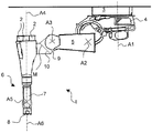
도 1 내지 도 3 은 로봇암 (1) 을 나타내며, 상기 로봇암은 잇달아 배치된, 그리고 관절들을 이용해 연결된 다수의 부재를 포함한다.1 to 3 show a robot arm 1, which comprises a plurality of members arranged one after another and connected by means of joints.
상기 부재들은 본 실시예의 경우 특히 고정식 또는 이동식 베이스 (3), 및 상기 베이스 (3) 에 대해 제 1 회전축 (A1) 둘레로 회전 가능하게 설치된 캐로셀 (4) 이다. 도 1 및 도 2 에 도시되어 있는 실시예의 경우 베이스 (3) 는 바닥에 고정되어 있다.These members are in particular a stationary or
상기 로봇암 (1) 의 그 밖의 부재들은 본 실시예의 경우 로커암 (5) 과, 암 (6) 과, 상세하게 도시되어 있지 않은 엔드 이펙터를 고정시키기 위한 예컨대 플랜지 (8) 로서 설계된 고정장치를 가지며 바람직하게는 다축인 로봇핸드 (7) 이다. 로커암 (5) 은 하부 단부에서, 예컨대 캐로셀 (4) 위의 상세히 도시되어 있지 않은 로커암 베어링 헤드에서, 제 2 회전축 (A2) 둘레로 선회 가능하게 설치되어 있다. 또한 로커암 (5) 의 상부 단부에는, 제 3 회전축 (A3) 둘레로 암 (6) 이 선회 가능하게 설치되어 있다. 상기 암은 단부쪽에서, 바람직하게는 3개의 회전축, 즉 제 4 회전축 (A4), 회전축 (A5) 및 제 6 회전축 (A6) 을 가진 로봇핸드 (7) 를 지지한다. 도 1 에 도시되어 있는 로봇암 (1) 의 상태에서, 제 4 회전축 (A4) 과 제 6 회전축 (A6) 은 서로 겹쳐진다. 이 이외에, 제 2 회전축 (A2) 과 제 3 회전축 (A3) 은 서로에 대해 평행으로 배치되어 있다.The other members of the robot arm 1 include a
상기 로봇암 (1) 은 특히 다관절 로봇의 부품이며, 상기 다관절 로봇은 상기 로봇암 (1) 이외에 상세히 도시되어 있지 않은 제어장치를 구비하며, 상기 제어장치는 일반적으로 알려져 있는 방식으로 예컨대 상기 다관절 로봇의 전기 구동부 (electric drive) 들과 연결되어 있다. 도 1 내지 도 3 에는, 로봇암 (1) 안에 및/또는 상기 로봇암에 고정되어 있는 이 전기 구동부들의 전기 모터 (2) 들 중 몇 개만 도시되어 있다. 도 1 내지 도 3 에 도시되어 있는 전기 모터 (2) 들은 로봇핸드 (7) 를 움직이기 위해 제공되어 있다. 상기 전기 구동부들의 파워일렉트로닉스 (power electronics) 는 예컨대 상세히 도시되어 있지 않은 제어 캐비닛의 하우징 내부에 배치되어 있고, 상기 제어 캐비닛의 내부에는 예컨대 상기 제어장치도 배치되어 있다. 상기 전기 구동부들의 파워일렉트로닉스는 로봇암 (1) 안에 및/또는 상기 로봇암에 배치되어 있을 수도 있다. 로봇핸드 (7) 의 전기 모터 (2) 들은 로커암 (5) 에 대해 배향된, 특히 암 (6) 의 단부 안에 및/또는 상기 단부에 배치되어 있다.The robot arm 1 is particularly a part of a multi-joint robot. The multi-joint robot includes a control device not shown in detail other than the robot arm 1, and the control device is, for example, And is connected to the electric drives of the articulated robot. In Figs. 1 to 3, only a few of the
본 실시예의 경우, 로봇암 (1) 은, 그의 부재들 (3 내지 7) 중 적어도 하나가 적어도 2개의 서로 다른 구성으로, 그의 이웃한 부재 (3-7) 에 대해 조립될 수 있도록 설계되어 있다. 특히, 이 부재는 상기 2개의 서로 다른 구성을 위해 제 1 방향으로 또는 가상의 조립축 (11) 과 관련하여 180°만큼 회전된 제 2 방향으로, 그의 이웃한 부재 (3-7) 에 대해 조립될 수 있다. 이는 특히 로커암 (5) 및/또는 암 (6) 을 위해 제공되어 있다. 이때, 가상의 조립축 (11) 은 로커암 (5) 의 각각의 회전축 (A2) 또는 암 (6) 의 회전축 (A3) 에 대해 직각으로 배치되어 있다.In the case of this embodiment, the robot arm 1 is designed so that at least one of its
예컨대, 암 (6) 이 로커암 (5) 에 대해 선택적으로 2개의 서로 다른 구성으로, 특히 선택적으로 제 1 방향으로 또는 조립축 (11) 과 관련하여 180°만큼 회전된 제 2 방향으로 조립 가능한 것을 달성하기 위해, 로봇암 (1) 은 본 실시예의 경우 고정장치 (9) 를 포함하며, 상기 고정장치는 제 3 회전축 (A3) 과 관련하여 선회 가능하게 로커암 (5) 의 상응하는 단부에 배치되어 있다. 암 (6) 은 로커암 (5) 에 대해 배향된 그의 단부에 대응 고정장치 (10) 를 포함하며, 상기 대응 고정장치를 이용해 암 (6) 은 특히 탈착 가능하게 고정장치 (9) 에 조립될 수 있다. 고정장치 (9) 와 대응 고정장치 (10) 는, 암 (6) 이 선택적으로 2개의 서로 다른 구성으로 고정장치 (9) 에 조립될 수 있도록 설계되어 있다. 상기 두 구성으로, 암 (6) 은 고정장치 (10) 와 관련하여, 그리고 이로써 로커암 (5) 과 관련하여 선택적으로 제 1 방향으로 또는 조립축 (11) 과 관련하여 180°만큼 회전된 제 2 방향으로 특히 탈착 가능하게 조립 가능하다. 도 1 에 도시되어 있는 도면에서 암 (6) 은 그의 정렬들 중 하나인 제 1 방향으로 고정장치 (10) 에 조립되어 있으며, 그리고 도 2 에 도시되어 있는 도면에서 암 (6) 은 상기 제 1 방향에 대해 조립축 (11) 과 관련하여 180°만큼 회전된 제 2 방향으로 고정장치 (10) 에 조립되어 있다.For example, the
예컨대 로봇암 (1) 의 작동영역, 즉 구동시 예컨대 그의 플랜지 (8) 또는 이른바 공구 중심점 (Tool Center Point) 을 갖는 암 (6) 이 가동될 수 있는 영역이 주 작동 영역 (A) 과 부분 작동 영역 (B) 으로 분할되면 (상기 영역들은 평면 (C) 에 의해 나뉘어져 있고, 이때 상기 평면 (C3) 은 제 2 회전축 (A2) 과 제 3 회전축 (A3) 을 통해 연장됨), 어떻게 암 (6) 이 고정장치 (9) 에 조립되어 있는 지에 따라 상기 작동공간의 상기 주 작동 영역 (A) 과 상기 부분 작동 영역 (B) 은 상기 로봇암 (1) 을 포함하는 로봇의 적용예에서 조정될 수 있다. 특히, 상기 작동공간의 상기 주 작동 영역 (A) 과 상기 부분 작동 영역 (B) 은 로커암 (5) 에 대한 암 (6) 의 조립에 상응하여 위치가 바뀔 수 있다.For example, an operating region of the robot arm 1, that is, an area where the
도 1 에 따른 본 실시예의 경우, 로봇암 (1) 은, 제 4 회전축 (A4) 이 바닥 조립에 있어서 제 3 회전축 (A3) 을 통과해 진행하도록 설계되어 있다. 이를 통해, 로커암 (5) 의 그리고 제 1 회전축 (A1) 의 간섭윤곽들에 대해 더 많은 공간이 확보된다. 이를 통해, 주 작동 영역 (A) 은, 도 1 에 도시되어 있는 바와 같이, 확장된다.In the case of this embodiment according to Fig. 1, the robot arm 1 is designed such that the fourth rotary shaft A4 passes through the third rotary shaft A3 in the bottom assembly. Thereby, more space is secured for the interference contours of the
본 실시예의 경우, 고정장치 (9) 는, 제 3 회전축 (A3) 에 대해 방사상으로 그리고 제 4 회전축 (A4) 에 대해 각도 ![]()
![]()
조립축 (11) 과 관련하여 180°만큼 회전된 도 2 에 따라 도시된 암 (6) 의 상응하는 조립체는 본 발명에 따르면 부분 작동 영역 (B) 이 주 작동 영역 (A) 에 상응하는 것을 가능하게 한다. 즉, 규정된 주 작동 영역 (A) 과 부분 작동 영역 (B) 이 반대로 될 수 있도록 실시 가능하다.The corresponding assembly of the
도 2 에 따른 암 (6) 의 조립체는 예컨대 천장에서의 로봇암 (1) 의 조립에 있어서 바람직할 수 있다. 천장에서의, 그의 베이스 (3) 를 가진 로봇암 (1) 의 조립체가 도 3 에 도시되어 있다.The assembly of the
예컨대 로봇핸드 (7) 에 할당된 전기 모터 (2) 들로 전기 에너지를 공급하기 위해, 로봇암 (1) 은 예컨대 도 4 에 도시되어 있는 전선 (12) 을 포함한다. 도 4 는 로커암 (5) 과 암 (6) 의 영역에서의 로봇암 (1) 의 단면도를 나타낸다. 이때, 제 3 회전축 (A3) 과 관련하여 로커암 (5) 을 선회시키기 위해 제공되어 있는 전기 모터는 참조부호 2a 로 표시되어 있다.For example, in order to supply electric energy to the
이 전선 (12) 의 개선된 케이블 루트를 위해, 고정장치 (9) 는 대칭적으로 형성되어 있을 수 있다. 이는 예컨대, 전선 (12) 이, 암 (6) 을 고정장치 (9) 에 고정시키기 위해 제공되어 있는 장착 플랜지를 중간 관통함으로써 달성될 수 있다.For an improved cable route of this
하지만, 도 4 에 도시되어 있는 바와 같이, 전선 (12) 을 위한 2개의 배전부 (13a, 13b) 가 암 (6) 에 제공되어 있을 수 있고, 상기 배전부들을 통해 선택적으로 암 (6) 의 조립에 따라 전선 (12) 은 로봇핸드 (7) 의 모터 (2) 들로의 연결부로 안내되어 있다. 두 배전부 (13a, 13b) 는 암 (6) 의 측면들에 특히 로봇핸드 (7) 의 모터 (2) 들의 영역에 대향되어 배치되어 있다.However, as shown in Fig. 4, two
Claims (11)
상기 부재들 (3-7) 중 적어도 하나는 선택적으로 적어도 2개의 구성으로, 그의 이웃한 부재 (3-7) 에 대해 조립 가능한 것을 특징으로 하는, 로봇암.A plurality of members 3-7 movable with respect to each other with respect to the axes A1-A6 and motors 2, 2a for moving the members 3-7 In the robot arm,
Characterized in that at least one of the members (3-7) is optionally assembled with respect to its neighboring member (3-7) in at least two configurations.
상응하는 상기 부재 (3-7) 는 탈착 가능하게, 부재의 이웃한 부재 (3-7) 에 대해 서로 다른 방향으로 조립 가능한, 로봇암.The method according to claim 1,
Wherein said corresponding member (3-7) is releasably assembleable in different directions with respect to the adjacent member (3-7) of the member.
상응하는 상기 부재 (3-7) 는 부재의 이웃한 부재 (3-7) 에 대해 선택적으로 제 1 방향으로 또는 가상의 조립축 (11) 과 관련하여 180°만큼 회전된 제 2 방향으로 조립 가능하며, 이때 상기 가상의 조립축 (11) 은 상기 이웃한 부재 (3-7) 의 회전축에 대해 직각인, 로봇암.3. The method according to claim 1 or 2,
The corresponding member 3-7 can be assembled in a first direction selectively with respect to the neighboring member 3-7 of the member or in a second direction rotated by 180 ° with respect to the virtual assembly axis 11 , Wherein the virtual assembly axis (11) is perpendicular to the rotation axis of the adjacent member (3-7).
상기 부재들 중 하나는 로커암 (5) 으로서 형성되어 있으며, 상기 부재들 중 그 밖의 것은 암 (6) 으로서 형성되어 있고, 그리고 상기 회전축들 중 하나는 로커암 축 (A2) 이고, 상기 로커암 축과 관련하여 상기 로커암 (5) 은 그의 단부들 중 하나에서 선회 가능하게 설치되어 있으며, 그리고 상기 회전축들 중 그 밖의 것은 회전축에 대해 평행인 암 축 (A3) 이고, 상기 암 축과 관련하여 상기 암 (6) 은 상기 로커암 (5) 의 다른 단부에 대해 선회 가능하게 설치되어 있는, 로봇암.4. The method according to any one of claims 1 to 3,
One of the members being formed as a rocker arm (5), the other of the members being formed as an arm (6) and one of the rotation axes being a rocker arm axis (A2) The rocker arm (5) is pivotally mounted at one of its ends with respect to the axis, and the other of the rotation axes is an arm axis (A3) parallel to the rotation axis, and in relation to the arm axis And the arm (6) is pivotally mounted to the other end of the rocker arm (5).
적어도 2개의 구성으로 선택적으로, 부재의 이웃한 부재 (3-7) 에 대해 조립 가능한 부재는 상기 로커암 (5) 이며, 상기 로커암은 특히 상기 암 (6) 에 대해 배향된 로커암의 단부와 함께 선택적으로 적어도 2개의 구성으로 캐로셀 (4) 에 대해 조립 가능하고, 상기 캐로셀에는, 상기 로커암 (5) 이 상기 로커암 축 (A2) 에 대해 선회 가능하게 배치되어 있는, 로봇암.5. The method of claim 4,
Optionally, in at least two configurations, the member that can be assembled relative to the adjacent member (3-7) of the member is the rocker arm (5), and the rocker arm is in particular an end of the rocker arm Wherein the rocker arm (5) is rotatably arranged with respect to the rocker arm axis (A2), the rocker arm (5) being rotatable relative to the rocker arm .
적어도 2개의 구성으로, 부재의 이웃한 부재 (3-7) 에 대해 조립 가능한 부재는 상기 암 (6) 이고, 상기 이웃한 부재는 상기 로커암 (5) 인, 로봇암.The method according to claim 4 or 5,
A robot arm (5) according to at least two of the claims, wherein the member which can be assembled with the neighboring member (3-7) of the member is the arm (6), and the neighboring member is the rocker arm (5).
제 1 고정장치 (9) 를 구비하며, 상기 제 1 고정장치는 상기 암 축 (A3) 에 대해 선회 가능하게 상기 로커암 (5) 에 설치되어 있고, 그리고 상기 제 1 고정장치에서, 상기 암 (6) 은 선택적으로 상기 적어도 2개의 구성으로 상기 로커암 (5) 에 대해 조립 가능한, 로봇암.7. The method according to any one of claims 4 to 6,
Wherein the first locking device is provided on the rocker arm 5 so as to be pivotable with respect to the arm shaft A3 and in the first locking device the arm 6) are selectively assembled with respect to said rocker arm (5) in said at least two configurations.
상기 로봇암의 상기 제 1 고정장치 (9) 는, 방사상으로 상기 암 축 (A3) 에 대해 그리고 상기 암 (6) 의 세로축 (A4) 에 대해 각도
Characterized in that the first locking device (9) of the robotic arm has an angle (?) With respect to the arm axis (A3) radially and against the longitudinal axis (A4)
상기 부재들 중 그 밖의 것들은 로봇핸드 (7) 로서 형성되어 있으며, 상기 로봇핸드는 단부쪽에, 엔드 이펙터를 고정시키기 위한 제 2 고정장치 (8) 를 구비하고, 그리고 상기 로봇핸드는 상기 로커암 (5) 에 대해 배향된 상기 암 (6) 의 단부에 고정되어 있으며, 이때 상기 로봇핸드 (7) 에 할당된 모터 (2) 들은 상기 로커암 (5) 에 대해 배향된 상기 암 (6) 의 단부 안에 및/또는 상기 단부에 배치되어 있는, 로봇암.9. The method according to any one of claims 4 to 8,
Wherein the other of said members is formed as a robot hand (7), said end being provided with a second fastening device (8) for fastening the end effector to said end, The motors 2 assigned to the robot hand 7 are fixed to the end of the arm 6 oriented with respect to the rocker arm 5, And / or at the end.
상기 로봇핸드 (7) 의 상기 모터 (2) 들과 연결된 전선 (12) 을 구비하며, 상기 전선은, 상기 암 (6) 을 제 1 고정장치 (9) 에 고정시키기 위해 제공되어 있는 장착 플랜지를 중간 관통하는, 로봇암.10. The method of claim 9,
And a wire 12 connected to the motors 2 of the robot hand 7. The wire has a mounting flange provided for fixing the arm 6 to the first fixing device 9 Middle penetrating, robotic arm.
상기 로봇핸드 (7) 의 상기 모터 (2) 들과 연결된 전선 (12) 을 구비하며, 이때 상기 암 (6) 은 상기 전선 (12) 을 위한 2개의 배전부 (13a, 13b) 를 구비하고, 상기 배전부들을 통해 선택적으로 상기 암 (6) 의 조립에 따라 상기 전선 (12) 은 상기 로봇핸드 (7) 의 상기 모터 (2) 들로의 연결부로 안내되어 있으며, 이때 특히 상기 배전부들 (13a, 13b) 은 상기 암 (6) 의 측면들에 특히 상기 로봇핸드 (7) 의 상기 모터 (2) 들의 영역에 대향되어 배치되어 있는 로봇암.10. The method of claim 9,
And a wire 12 connected to the motors 2 of the robot hand 7. The arm 6 is provided with two power distribution parts 13a and 13b for the wire 12, The electric wire 12 is guided to the connection portion of the robot hand 7 to the motors 2 according to the assembly of the arm 6 selectively through the power distributing portions, 13b) are arranged on the sides of the arm (6), in particular facing the area of the motors (2) of the robot hand (7).
Applications Claiming Priority (2)
| Application Number | Priority Date | Filing Date | Title |
|---|---|---|---|
| DE102012223063.7A DE102012223063A1 (en) | 2012-12-13 | 2012-12-13 | robot arm |
| DE102012223063.7 | 2012-12-13 |
Publications (2)
| Publication Number | Publication Date |
|---|---|
| KR20140077117A true KR20140077117A (en) | 2014-06-23 |
| KR102206418B1 KR102206418B1 (en) | 2021-01-22 |
Family
ID=49765308
Family Applications (1)
| Application Number | Title | Priority Date | Filing Date |
|---|---|---|---|
| KR1020130154200A Active KR102206418B1 (en) | 2012-12-13 | 2013-12-11 | Robot arm |
Country Status (5)
| Country | Link |
|---|---|
| US (1) | US9120229B2 (en) |
| EP (1) | EP2743039B1 (en) |
| KR (1) | KR102206418B1 (en) |
| CN (1) | CN103862464B (en) |
| DE (1) | DE102012223063A1 (en) |
Families Citing this family (10)
| Publication number | Priority date | Publication date | Assignee | Title |
|---|---|---|---|---|
| USD776735S1 (en) * | 2014-03-28 | 2017-01-17 | Abb Technology Ltd. | Industrial robot |
| EP2944259A1 (en) * | 2014-05-15 | 2015-11-18 | Buck Engineering & Consulting GmbH | Patient positioning device |
| JP2016068204A (en) * | 2014-09-30 | 2016-05-09 | セイコーエプソン株式会社 | robot |
| CN105150072A (en) * | 2015-08-04 | 2015-12-16 | 西宁科进工业设计有限公司 | Polishing machine |
| TWD176690S (en) * | 2015-09-24 | 2016-06-21 | 上銀科技股份有限公司 | Part of the instrument base |
| JP1629907S (en) * | 2017-10-23 | 2019-04-22 | ||
| JP6875348B2 (en) * | 2018-10-17 | 2021-05-26 | ファナック株式会社 | Robot and 1st arm member |
| USD1056009S1 (en) * | 2022-01-30 | 2024-12-31 | Abb Schweiz Ag | Industrial robot |
| USD1048130S1 (en) * | 2022-06-17 | 2024-10-22 | Neura Robotics GmbH | Robot |
| CN115139332B (en) * | 2022-07-27 | 2025-10-28 | 武汉吉杰科技有限公司 | Robotic arm assembly |
Citations (2)
| Publication number | Priority date | Publication date | Assignee | Title |
|---|---|---|---|---|
| KR200228423Y1 (en) * | 2000-12-21 | 2001-06-15 | 현대중공업주식회사 | Dual Orientation socketable cannon plate for hand application cable of palletizing robot |
| KR20120089581A (en) * | 2011-02-02 | 2012-08-13 | 쿠카 로보테르 게엠베하 | Method for referencing a drive position of at least one electric drive |
Family Cites Families (23)
| Publication number | Priority date | Publication date | Assignee | Title |
|---|---|---|---|---|
| FR2461556A1 (en) * | 1979-07-18 | 1981-02-06 | Bretagne Atel Chantiers | REMOTE HANDLING ARM |
| SE454659B (en) * | 1983-09-01 | 1988-05-24 | Asea Ab | ROBOT WRIST |
| JPS62166978A (en) * | 1986-01-20 | 1987-07-23 | フアナツク株式会社 | Arm structure of industrial robot |
| SE8605070L (en) * | 1986-11-26 | 1988-05-27 | Komatsu Mfg Co Ltd | BUILDING ROBOT ARM |
| US4787270A (en) * | 1987-02-11 | 1988-11-29 | Cincinnati Milacron Inc. | Robotic manipulator |
| JPH01146676A (en) * | 1987-11-30 | 1989-06-08 | Fanuc Ltd | Horizontal joint type robot having arm inversion structure |
| JPH074137Y2 (en) * | 1988-04-07 | 1995-02-01 | 株式会社不二越 | A floor-standing robot that can be used as a ceiling-mounted or wall-mounted robot |
| JPH02311285A (en) * | 1989-05-19 | 1990-12-26 | Toyoda Mach Works Ltd | Industrial robot |
| US5355063A (en) * | 1990-11-01 | 1994-10-11 | Westinghouse Electric Corp. | Robotic system for servicing the heat exchanger tubes of a nuclear steam generator |
| DE4137894A1 (en) * | 1991-11-18 | 1992-05-27 | Stefan Roth | Articulated joint for machine part - consists of four connected parts of which two are at angle to other two |
| DE4431842C2 (en) * | 1994-09-07 | 1998-10-01 | Gmd Gmbh | Electronically controllable device |
| JP2659172B2 (en) * | 1995-01-19 | 1997-09-30 | 豊田工機株式会社 | Articulated robot |
| JPH1148172A (en) * | 1997-08-08 | 1999-02-23 | Nachi Fujikoshi Corp | Swing arm |
| US5887800A (en) * | 1997-09-03 | 1999-03-30 | Fanuc Robotics North America, Inc. | Robot wrist and spray applicator |
| FR2809048B1 (en) * | 2000-05-18 | 2002-10-11 | Commissariat Energie Atomique | CONTROL ARM |
| SE0301754D0 (en) * | 2003-06-13 | 2003-06-13 | Abb Ab | Industrial Robot |
| US7137578B2 (en) * | 2003-12-26 | 2006-11-21 | Task Force Tips, Inc. | Segmented monitor |
| JP4520268B2 (en) * | 2004-09-28 | 2010-08-04 | 川崎重工業株式会社 | robot |
| CA2497250A1 (en) * | 2005-02-14 | 2006-08-14 | Mcluckie, Brian | Rail and saddle for a gantry robot and a gantry robot including the same |
| WO2010040215A1 (en) * | 2008-10-06 | 2010-04-15 | Kinova | Portable robotic arm |
| IT1395114B1 (en) * | 2009-07-28 | 2012-09-05 | Itel Telecomunicazioni S R L | ROBOTIC SYSTEM FOR THE POSITIONING OF A PATIENT COMPARED TO AT LEAST ONE PARTICLE SOURCE |
| JP5724205B2 (en) * | 2010-04-15 | 2015-05-27 | セイコーエプソン株式会社 | Robot and robot cell |
| US20120215358A1 (en) * | 2011-01-31 | 2012-08-23 | Robotex Inc. | Robotic arm system |
-
2012
- 2012-12-13 DE DE102012223063.7A patent/DE102012223063A1/en not_active Withdrawn
-
2013
- 2013-12-03 EP EP13195579.1A patent/EP2743039B1/en active Active
- 2013-12-11 KR KR1020130154200A patent/KR102206418B1/en active Active
- 2013-12-12 US US14/104,643 patent/US9120229B2/en active Active
- 2013-12-13 CN CN201310685082.3A patent/CN103862464B/en active Active
Patent Citations (2)
| Publication number | Priority date | Publication date | Assignee | Title |
|---|---|---|---|---|
| KR200228423Y1 (en) * | 2000-12-21 | 2001-06-15 | 현대중공업주식회사 | Dual Orientation socketable cannon plate for hand application cable of palletizing robot |
| KR20120089581A (en) * | 2011-02-02 | 2012-08-13 | 쿠카 로보테르 게엠베하 | Method for referencing a drive position of at least one electric drive |
Also Published As
| Publication number | Publication date |
|---|---|
| CN103862464A (en) | 2014-06-18 |
| US9120229B2 (en) | 2015-09-01 |
| US20140165771A1 (en) | 2014-06-19 |
| EP2743039A1 (en) | 2014-06-18 |
| DE102012223063A1 (en) | 2014-06-18 |
| EP2743039B1 (en) | 2024-03-06 |
| KR102206418B1 (en) | 2021-01-22 |
| CN103862464B (en) | 2018-11-09 |
Similar Documents
| Publication | Publication Date | Title |
|---|---|---|
| KR20140077117A (en) | Robot arm | |
| CN105307824B (en) | Industrial robot with a drive layout set on a cantilever | |
| RU2579712C2 (en) | Robot-manipulator | |
| JP5884785B2 (en) | robot | |
| EP3184262A1 (en) | Multi-axis industrial robot, in particular of a scara type | |
| JP5949693B2 (en) | robot | |
| CA2950973A1 (en) | Multi-axis industrial robot, in particular of a scara type | |
| JP4822061B2 (en) | Double arm robot | |
| KR20130043678A (en) | Ceiling-mounted scara robot | |
| US20160031095A1 (en) | Robot | |
| JP6691147B2 (en) | Parallel link robot | |
| KR101502224B1 (en) | Industrial robot | |
| US20160031094A1 (en) | Robot | |
| JP2018502732A (en) | Machine tool processing unit and machine tool | |
| KR101086295B1 (en) | Articulated robot | |
| JP2006007332A (en) | Industrial robot | |
| KR101494539B1 (en) | Multipurpose robotic arm | |
| JP6182064B2 (en) | robot | |
| TWM540031U (en) | Robot arm device | |
| JP2013158896A (en) | Horizontally articulated robot | |
| KR101201724B1 (en) | manipulator | |
| JP6316701B2 (en) | Link device | |
| KR101201691B1 (en) | joint drive apparatus | |
| JP6053991B2 (en) | Positioning device | |
| CN217371071U (en) | Automatic welding manipulator for connecting pipe |
Legal Events
| Date | Code | Title | Description |
|---|---|---|---|
| PA0109 | Patent application |
St.27 status event code: A-0-1-A10-A12-nap-PA0109 |
|
| PG1501 | Laying open of application |
St.27 status event code: A-1-1-Q10-Q12-nap-PG1501 |
|
| PN2301 | Change of applicant |
St.27 status event code: A-3-3-R10-R13-asn-PN2301 St.27 status event code: A-3-3-R10-R11-asn-PN2301 |
|
| P11-X000 | Amendment of application requested |
St.27 status event code: A-2-2-P10-P11-nap-X000 |
|
| P13-X000 | Application amended |
St.27 status event code: A-2-2-P10-P13-nap-X000 |
|
| PA0201 | Request for examination |
St.27 status event code: A-1-2-D10-D11-exm-PA0201 |
|
| D13-X000 | Search requested |
St.27 status event code: A-1-2-D10-D13-srh-X000 |
|
| D14-X000 | Search report completed |
St.27 status event code: A-1-2-D10-D14-srh-X000 |
|
| E902 | Notification of reason for refusal | ||
| PE0902 | Notice of grounds for rejection |
St.27 status event code: A-1-2-D10-D21-exm-PE0902 |
|
| T11-X000 | Administrative time limit extension requested |
St.27 status event code: U-3-3-T10-T11-oth-X000 |
|
| E13-X000 | Pre-grant limitation requested |
St.27 status event code: A-2-3-E10-E13-lim-X000 |
|
| P11-X000 | Amendment of application requested |
St.27 status event code: A-2-2-P10-P11-nap-X000 |
|
| P13-X000 | Application amended |
St.27 status event code: A-2-2-P10-P13-nap-X000 |
|
| E701 | Decision to grant or registration of patent right | ||
| PE0701 | Decision of registration |
St.27 status event code: A-1-2-D10-D22-exm-PE0701 |
|
| GRNT | Written decision to grant | ||
| PR0701 | Registration of establishment |
St.27 status event code: A-2-4-F10-F11-exm-PR0701 |
|
| PR1002 | Payment of registration fee |
St.27 status event code: A-2-2-U10-U11-oth-PR1002 Fee payment year number: 1 |
|
| PG1601 | Publication of registration |
St.27 status event code: A-4-4-Q10-Q13-nap-PG1601 |
|
| PR1001 | Payment of annual fee |
St.27 status event code: A-4-4-U10-U11-oth-PR1001 Fee payment year number: 4 |
|
| PR1001 | Payment of annual fee |
St.27 status event code: A-4-4-U10-U11-oth-PR1001 Fee payment year number: 5 |
|
| PR1001 | Payment of annual fee |
St.27 status event code: A-4-4-U10-U11-oth-PR1001 Fee payment year number: 6 |
|
| U11 | Full renewal or maintenance fee paid |
Free format text: ST27 STATUS EVENT CODE: A-4-4-U10-U11-OTH-PR1001 (AS PROVIDED BY THE NATIONAL OFFICE) Year of fee payment: 6 |