KR20140077149A - Transfer device - Google Patents
Transfer device Download PDFInfo
- Publication number
- KR20140077149A KR20140077149A KR1020147006181A KR20147006181A KR20140077149A KR 20140077149 A KR20140077149 A KR 20140077149A KR 1020147006181 A KR1020147006181 A KR 1020147006181A KR 20147006181 A KR20147006181 A KR 20147006181A KR 20140077149 A KR20140077149 A KR 20140077149A
- Authority
- KR
- South Korea
- Prior art keywords
- support
- support arm
- upper body
- arm
- angle position
- Prior art date
- Legal status (The legal status is an assumption and is not a legal conclusion. Google has not performed a legal analysis and makes no representation as to the accuracy of the status listed.)
- Granted
Links
Images


Classifications
-
- A—HUMAN NECESSITIES
- A61—MEDICAL OR VETERINARY SCIENCE; HYGIENE
- A61G—TRANSPORT, PERSONAL CONVEYANCES, OR ACCOMMODATION SPECIALLY ADAPTED FOR PATIENTS OR DISABLED PERSONS; OPERATING TABLES OR CHAIRS; CHAIRS FOR DENTISTRY; FUNERAL DEVICES
- A61G7/00—Beds specially adapted for nursing; Devices for lifting patients or disabled persons
- A61G7/10—Devices for lifting patients or disabled persons, e.g. special adaptations of hoists thereto
- A61G7/1013—Lifting of patients by
- A61G7/1017—Pivoting arms, e.g. crane type mechanisms
-
- A—HUMAN NECESSITIES
- A61—MEDICAL OR VETERINARY SCIENCE; HYGIENE
- A61G—TRANSPORT, PERSONAL CONVEYANCES, OR ACCOMMODATION SPECIALLY ADAPTED FOR PATIENTS OR DISABLED PERSONS; OPERATING TABLES OR CHAIRS; CHAIRS FOR DENTISTRY; FUNERAL DEVICES
- A61G7/00—Beds specially adapted for nursing; Devices for lifting patients or disabled persons
- A61G7/10—Devices for lifting patients or disabled persons, e.g. special adaptations of hoists thereto
- A61G7/104—Devices carried or supported by
- A61G7/1046—Mobile bases, e.g. having wheels
-
- A—HUMAN NECESSITIES
- A61—MEDICAL OR VETERINARY SCIENCE; HYGIENE
- A61G—TRANSPORT, PERSONAL CONVEYANCES, OR ACCOMMODATION SPECIALLY ADAPTED FOR PATIENTS OR DISABLED PERSONS; OPERATING TABLES OR CHAIRS; CHAIRS FOR DENTISTRY; FUNERAL DEVICES
- A61G2200/00—Information related to the kind of patient or his position
- A61G2200/30—Specific positions of the patient
- A61G2200/32—Specific positions of the patient lying
- A61G2200/325—Specific positions of the patient lying prone
-
- A—HUMAN NECESSITIES
- A61—MEDICAL OR VETERINARY SCIENCE; HYGIENE
- A61G—TRANSPORT, PERSONAL CONVEYANCES, OR ACCOMMODATION SPECIALLY ADAPTED FOR PATIENTS OR DISABLED PERSONS; OPERATING TABLES OR CHAIRS; CHAIRS FOR DENTISTRY; FUNERAL DEVICES
- A61G7/00—Beds specially adapted for nursing; Devices for lifting patients or disabled persons
- A61G7/10—Devices for lifting patients or disabled persons, e.g. special adaptations of hoists thereto
- A61G7/1073—Parts, details or accessories
- A61G7/1076—Means for rotating around a vertical axis
-
- A—HUMAN NECESSITIES
- A61—MEDICAL OR VETERINARY SCIENCE; HYGIENE
- A61G—TRANSPORT, PERSONAL CONVEYANCES, OR ACCOMMODATION SPECIALLY ADAPTED FOR PATIENTS OR DISABLED PERSONS; OPERATING TABLES OR CHAIRS; CHAIRS FOR DENTISTRY; FUNERAL DEVICES
- A61G7/00—Beds specially adapted for nursing; Devices for lifting patients or disabled persons
- A61G7/10—Devices for lifting patients or disabled persons, e.g. special adaptations of hoists thereto
- A61G7/1073—Parts, details or accessories
- A61G7/1082—Rests specially adapted for
- A61G7/1086—Upper body
-
- A—HUMAN NECESSITIES
- A61—MEDICAL OR VETERINARY SCIENCE; HYGIENE
- A61G—TRANSPORT, PERSONAL CONVEYANCES, OR ACCOMMODATION SPECIALLY ADAPTED FOR PATIENTS OR DISABLED PERSONS; OPERATING TABLES OR CHAIRS; CHAIRS FOR DENTISTRY; FUNERAL DEVICES
- A61G7/00—Beds specially adapted for nursing; Devices for lifting patients or disabled persons
- A61G7/10—Devices for lifting patients or disabled persons, e.g. special adaptations of hoists thereto
- A61G7/1073—Parts, details or accessories
- A61G7/1082—Rests specially adapted for
- A61G7/1092—Rests specially adapted for the arms
-
- A—HUMAN NECESSITIES
- A61—MEDICAL OR VETERINARY SCIENCE; HYGIENE
- A61G—TRANSPORT, PERSONAL CONVEYANCES, OR ACCOMMODATION SPECIALLY ADAPTED FOR PATIENTS OR DISABLED PERSONS; OPERATING TABLES OR CHAIRS; CHAIRS FOR DENTISTRY; FUNERAL DEVICES
- A61G7/00—Beds specially adapted for nursing; Devices for lifting patients or disabled persons
- A61G7/10—Devices for lifting patients or disabled persons, e.g. special adaptations of hoists thereto
- A61G7/1073—Parts, details or accessories
- A61G7/1082—Rests specially adapted for
- A61G7/1096—Knee, upper or lower leg
Landscapes
- Health & Medical Sciences (AREA)
- Nursing (AREA)
- Life Sciences & Earth Sciences (AREA)
- Animal Behavior & Ethology (AREA)
- General Health & Medical Sciences (AREA)
- Public Health (AREA)
- Veterinary Medicine (AREA)
- Invalid Beds And Related Equipment (AREA)
Abstract
이승자에게 무리한 자세를 강요하지 않고 필요한 대로 이승할 수 있는 이승 장치를 제공하는 것.
바닥면(4)에 설치되는 지지 구조체(6)와, 이승자(P)의 상체를 받아들이는 받아들임 각도 위치와 상체를 들어올리는 들어올림 각도 위치 사이를 요동이 자유롭게 지지 구조체(6)에 장착된 지지 암(8)과, 지지 암(8)의 선단부에 부착된 상체 지지부(10)를 구비한 이승 장치. 지지 암(8)의 상부(8a)는 그 하부(8b)에 대하여 받아들임측으로 경사져 있다. 이승할 때에는, 지지 암(8)이 받아들임 각도 위치에 위치되고, 이 상태에서 상체 지지부(10)에 이승자(P)의 상체가 받아들여지고, 그 후 지지 암(8)이 받아들임 각도 위치로부터 들어올림 각도 위치로 요동되어 이승자(P)를 들어올린다.Providing a bridge device that allows the passengers to ride as needed without imposing excessive posture.
The supporting structure 6 provided on the bottom surface 4 and the lifting angle position in which the upper body of the occupant P is received and the receiving angular position for lifting the upper body are swingably attached to the supporting structure 6 A support arm (8); and an upper body support part (10) attached to a distal end of the support arm (8). The upper portion 8a of the support arm 8 is inclined to the receiving side with respect to the lower portion 8b thereof. The support arm 8 is positioned at the acceptance angular position and the upper body of the passenger P is received in the upper body support portion 10 in this state and then the support arm 8 is received from the acceptance angular position Up position to lift the occupant (P).

Description
본 발명은 고령자나 장애를 가진 사람 등의 개호(介護)가 필요한 사람을 휠체어 등에 이승(移乘)할 때에 사용하는 이승 장치에 관한 것이다.The present invention relates to a winch device used for transferring a person who is in need of care such as an elderly person or a person with a disability to a wheelchair or the like.
개호가 필요한 사람을 휠체어 등에 이승하는 이승 장치로서, 턴테이블과, 이 턴테이블에 세워져 설치된 지주와, 이 지주의 선단부에 장착된 신체 지지부와, 지주를 경동시키기 위한 경동 장치와, 경동 장치를 구동하기 위한 구동 모터를 구비한 것이 제안되어 있다(예를 들면, 특허문헌 1 참조). 이 이승 장치에서는, 이승자(개호가 필요한 사람)를 이승할 때에, 경동 장치에 의해 지주를 경동시켜 신체 지지부를 경사 상태로 하고, 이 경사 상태에서 신체 지지부 위에 이승자의 상체를 덮어씌우듯이 하여 태운다. 그리고, 경동 장치에 의해 지주를 원래의 직립 상태로 되돌리고, 이승자의 몸을 받치고 턴테이블을 회전시켜 소정의 각도 위치에 위치시킨다. 그 후, 지주를 다시 경동시키고, 신체 지지부에 지지된 이승자를 휠체어 등에 태우고, 이렇게 하여 이승자를 예를 들면 베드로부터 휠체어로 이승시킬 수 있다.And a tilt device for tilting the tilting device, a tilting device for tilting the tilting device, a tilting device for tilting the tilting device, and a tilting device for tilting the tilting device. (For example, refer to Patent Document 1). In this skipping device, when the skipper (person requiring nursing care) is trained, the trunk is tilted by the tilting device to tilt the body supporting portion, and in this inclined state, the trunk is covered with the upper body of the occupant on the body supporting portion . Then, the support is returned to its original upright state by the tilting device, the host is supported, and the turntable is rotated and positioned at a predetermined angular position. After that, the proprietor is touched again, the assistant who is supported by the body support is put on the wheelchair, and thus the believer can be transferred from the bed to the wheelchair, for example.
그러나, 상기 서술한 이승 장치에는 다음과 같은 해결해야 할 문제가 존재한다. 첫번째로, 이승자는 지주의 선단부의 신체 지지부에 덮어씌우듯이 하여 타게 되고, 또 방향을 바꿀 때에는 지주를 직립 상태로 되돌려 턴테이블을 회동시키게 된다. 이러한 점에서, 신체 지지부에 탄 상태에서는, 이승자에게 상당히 무리한 자세를 강요하게 되고, 또 신체 지지부에 탄 상태는 상당히 불안정한 상태가 되어, 그러므로 사용상 편의의 면에서 추가적인 개량이 요망된다.However, the above-described skewer has the following problem to be solved. First, the rider is burdened on the body support of the tip of the strut, and when the direction is changed, the strut is returned to the upright state to turn the turntable. In this respect, in a state in which the body supporting portion is burnt, the occupant is forced to have an unreasonable posture and the state of the body supporting portion is considerably unstable. Therefore, further improvement is desired in terms of convenience in use.
두번째로, 신체 지지부에 탄 상태는 상당히 불안정한 상태가 되는 점에서, 개호가 필요한 사람이 혼자서 조작하는 것은 어렵고, 개호자의 도움을 받아 사용하게 되어, 개호가 필요한 사람의 자립 지원형의 것이라고는 할 수 없다.Secondly, it is difficult for a person who needs nursing care to operate it alone because it is in a state of considerable instability, and it is difficult to operate it alone, and it is used with the help of a nursing care person. none.
본 발명의 목적은, 이승자에게 무리한 자세를 강요하지 않고 이승자를 필요한 대로 이승할 수 있는 이승 장치를 제공하는 것이다.An object of the present invention is to provide a win-win device capable of winning a winner as needed without imposing an unreasonable posture on the winner.
본 발명의 다른 목적은, 개호가 필요한 사람의 자립 지원형의 것으로서 적용할 수 있는 이승 장치를 제공하는 것이다.Another object of the present invention is to provide a winner device which can be applied as a self-support type of a person who needs nursing care.
본 발명의 청구항 1에 기재된 이승 장치는, 바닥면에 설치되는 지지 구조체와, 이승자의 상체를 받아들이는 받아들임 각도 위치와 상체를 들어올리는 들어올림 각도 위치 사이를 요동이 자유롭게 상기 지지 구조체에 장착된 지지 암과, 상기 지지 암의 선단부에 부착된 상체 지지부를 구비하고, 상기 지지 암의 상부는 그 하부에 대하여 받아들임측으로 경사져 있고,[0012] According to a first aspect of the present invention, there is provided a false twisting apparatus comprising: a support structure provided on a floor; a support structure mounted on the support structure so as to be freely swingable between an angular position for accepting the upper body of the occupant and a lifting angle position for lifting the upper body; And an upper body support portion attached to a distal end portion of the support arm, wherein an upper portion of the support arm is inclined toward an acceptance side with respect to a lower portion thereof,
이승할 때에는, 상기 지지 암이 상기 받아들임 각도 위치에 위치되고, 상기 받아들임 각도 위치에 있는 상기 지지 암의 상기 상체 지지부에 이승자의 상체가 받아들여지고, 그 후 상기 지지 암이 상기 받아들임 각도 위치로부터 상기 들어올림 각도 위치로 요동되어 이승자를 들어올리는 것을 특징으로 한다.And when the support arm is positioned at the acceptance angular position, the upper body of the occupant is received in the upper body support of the support arm at the acceptance angular position, And is lifted up to a lifting angle position to raise the occupant.
또, 본 발명의 청구항 2에 기재된 이승 장치에서는, 상기 지지 구조체는 바닥면에 설치되는 지지 본체와, 상기 지지 본체에 대하여 회전이 자유로운 지지 회전판을 구비하고, 상기 지지 회전판에 상기 지지 암이 요동이 자유롭게 장착되고, 이승자의 양 발은 상기 지지 회전판에 실리는 것을 특징으로 한다.According to a second aspect of the present invention, the support structure includes a support body provided on a bottom surface of the support structure, and a support rotation plate that is rotatable with respect to the support body, And the two feet of the occupant are mounted on the supporting rotary plate.
또, 본 발명의 청구항 3에 기재된 이승 장치에서는, 상기 지지 회전판은 상기 지지 본체에 대하여 소정의 위치 관계가 되는 홈 각도 위치로부터 소정 방향으로 90도 선회한 제1 선회 각도 위치와, 상기 홈 각도 위치로부터 소정 방향에 대하여 반대 방향으로 90도 선회한 제2 선회 각도 위치 사이를 선회가 자유로운 것을 특징으로 한다.According to a second aspect of the present invention, there is provided a winch device, wherein the support rotation plate includes a first rotation angle position rotated 90 degrees in a predetermined direction from a groove angle position having a predetermined positional relationship with the support body, And a second turning angle position rotated 90 degrees in a direction opposite to the predetermined direction from the second turning angle position.
또, 본 발명의 청구항 4에 기재된 이승 장치에서는, 상기 지지 회전판과 상기 지지 암 사이에는, 상기 지지 암을 구동하기 위한 신축 기구가 개재되고, 상기 신축 기구가 신장 상태에 있으면, 상기 지지 암이 상기 받아들임 각도 위치에 유지되고, 상기 신축 기구가 수축 상태가 되면, 상기 지지 암이 상기 들어올림 각도 위치에 위치되는 것을 특징으로 한다.According to
또, 본 발명의 청구항 5에 기재된 이승 장치에서는, 상기 지지 회전판과 상기 지지 암 사이에는, 상기 지지 암을 상기 들어올림 각도 위치를 향하여 탄성적으로 편의(偏倚)하는 탄성 편의 수단이 개재되어 있는 것을 특징으로 한다.According to a fifth aspect of the present invention, there is provided an elastic piece means between the support rotary plate and the support arm for elastically biasing the support arm toward the lifting angle position .
또, 본 발명의 청구항 6에 기재된 이승 장치에서는, 상기 지지 암의 양측에는 이승자의 양 무릎을 맞닿게 하여 지지하기 위한 무릎 접촉 지지부가 배열설치되고, 이승할 때에는, 이승자의 양 무릎이 상기 무릎 접촉 지지부에 맞닿은 상태에서 상체가 상기 지지 암의 상기 상체 지지부에 받아들여지는 것을 특징으로 한다.In the winch device according to
또, 본 발명의 청구항 7에 기재된 이승 장치에서는, 상기 상체 지지부는 이승자의 상체를 지지하기 위한 본체 지지부를 구비하고, 상기 본체 지지부는 상기 지지 암이 상기 받아들임 각도 위치에 있을 때에는 수평 방향을 기준으로 전방을 향하여 50~60도 상방으로 경사져 뻗는 상태로 유지되고, 상기 지지 암이 상기 들어올림 각도 위치에 있을 때에는 수평 방향을 기준으로 전방을 향하여 15~25도 상방을 향하여 경사져 뻗는 상태로 유지되며, 상기 지지 암은 상기 받아들임 각도 위치에 있어서의 상기 본체 지지부의 경사 각도와 상기 들어올림 각도 위치에 있어서의 상기 본체 지지부의 경사 각도의 경사 각도차의 범위에 걸쳐 요동되는 것을 특징으로 한다.In the winch device according to claim 7 of the present invention, the upper body supporting part includes a body supporting part for supporting the upper body of the occupant, and when the supporting arm is at the receiving angular position, When the support arm is in the lifting angle position, it is held in a state of inclining upwardly by 15 to 25 degrees in the forward direction with respect to the horizontal direction when the support arm is in the lifting angle position, And the support arm is swung over a range of the inclination angle of the main body support portion at the acceptance angular position and the inclination angle difference of the inclination angle of the main body support portion at the lift angle position.
또, 본 발명의 청구항 8에 기재된 이승 장치에서는, 상기 상체 지지부의 상기 본체 지지부의 양단부에는, 또한 상방으로 돌출하는 돌출 지지부가 설치되고, 상기 돌출 지지부는 이승자의 양 팔을 지지하는 것을 특징으로 한다.According to
또, 본 발명의 청구항 9에 기재된 이승 장치에서는, 상기 지지 회전판에는 상기 지지 구조체의 전측부를 덮기 위한 하우징이 부착되고, 상기 하우징의 상면에는 상기 지지 암의 요동 범위에 대응하여 개구가 설치되어 있고, 또 상기 지지 암에는 상기 개구를 덮기 위한 가늘고 긴 안전 커버가 부착되어 있고, 상기 안전 커버는 상기 지지 암의 요동에 따라 상기 하우징의 내측에서 상기 개구를 따라 이동하는 것을 특징으로 한다.According to claim 9 of the present invention, a housing for covering a front portion of the support structure is attached to the support rotary plate, and an opening is provided on the upper surface of the housing corresponding to the swing range of the support arm And the support arm is provided with an elongated safety cover for covering the opening, and the safety cover moves along the opening from the inside of the housing according to the swinging motion of the support arm.
또, 본 발명의 청구항 10에 기재된 이승 장치에서는, 상기 지지 회전판의 전단부에는 상기 지지 구조체를 이동시키기 위한 이동용 캐스터가 설치되고, 상기 이동 캐스터는 상기 지지 본체로부터 하방으로 돌출하여 바닥면에 작용하는 돌출 위치와, 이 바닥면으로부터 상방으로 후퇴하는 후퇴 위치 사이를 이동이 자유로운 것을 특징으로 한다.According to a twelfth aspect of the present invention, a movable castor for moving the support structure is provided at a front end portion of the support rotary plate, the movable castor projects downward from the support main body and acts on the bottom surface And is movable between a protruding position and a retreat position that is upwardly retracted from the bottom surface.
또, 본 발명의 청구항 11에 기재된 이승 장치에서는, 상기 지지 암에는 조작 레버가 이동이 자유롭게 설치되어 있음과 아울러, 상기 조작 레버에 관련하여, 누름 부재가 선회가 자유롭게 설치되어 있고, 또 상기 지지 회전판에는 상기 이동용 캐스터를 상기 돌출 위치에 위치시키기 위한 이동 로드가 이동이 자유롭게 설치되고, 상기 이동용 캐스터는 상기 이동 로드에 의해 요동되는 요동 부착 부재에 부착되어 있고, 상기 조작 레버를 당겨 조작하면, 상기 누름 부재가 작용 위치에 위치되고, 이러한 상태에서 상기 지지 암을 상기 받아들임 각도 위치로부터 상기 들어올림 각도 위치까지 요동하면, 상기 누름 부재가 상기 이동 로드를 통하여 상기 요동 부착 부재에 작용하고, 상기 요동 부착 부재가 하방으로 요동하여 상기 이동용 캐스터가 상기 후퇴 위치로부터 상기 돌출 위치에 위치되는 것을 특징으로 한다.According to claim 11 of the present invention, the support arm is movably provided on the support arm, the pushing member is provided so as to be capable of turning with respect to the operation lever, The moving caster is attached to a swing attachment member which is pivoted by the moving rod, and when the operation lever is pulled and operated, And when the support arm is swung from the acceptance angular position to the lifting angle position in this state, the pushing member acts on the swing attachment member via the movement rod, and the swing attachment member The moving caster is moved backward Characterized in that the position from the projecting position.
또한, 본 발명의 청구항 12에 기재된 이승 장치에서는, 상기 신축 기구를 작동 제어하기 위한 조작 유닛이 상기 상체 지지부에 설치되어 있는 것을 특징으로 한다.According to a twelfth aspect of the present invention, an operation unit for controlling the operation of the extensible mechanism is provided on the upper body supporting portion.
본 발명의 청구항 1에 기재된 이승 장치에 의하면, 바닥면에 설치되는 지지 구조체와, 이 지지 구조체에 요동이 자유롭게 장착된 지지 암과, 지지 암의 선단부에 부착된 상체 지지부를 구비하고 있으므로, 상체 지지부는 1회동 지지점·1관절을 가지는 지지 암에 의해 지지되고, 비교적 간단한 구성으로써 상체 지지부를 지지할 수 있다. 또, 지지 암을 받아들임 각도 위치에 위치시킴으로써, 이승자의 상체를 상체 지지부에 받아들일 수 있고, 또 지지 암을 들어올림 각도 위치에 위치시킴으로써, 이승자를 들어올려 필요한 대로 이승시킬 수 있다. 또, 지지 암의 상부가 그 하부에 대하여 받아들임측으로 경사져 있으므로, 받아들임 각도 위치에 있어서는, 상체 지지부가 이승자측을 향하게 되고, 이것에 의해, 이승자의 상체 지지부로의 받아들임이 용이하게 되어, 개호가 필요한 사람이라도 혼자서 사용하는 것이 가능하게 된다.According to the first aspect of the present invention, since the support structure provided on the bottom surface, the support arm mounted on the support structure so as to be freely rockable, and the upper body support portion attached to the distal end portion of the support arm, Is supported by a supporting arm having one rotation supporting point and one joint, and can support the upper body supporting portion with a relatively simple structure. Further, by positioning the support arm at the receiving angular position, the upper body of the occupant can be received by the upper body support portion, and the support arm can be positioned at the lifting angular position, so that the occupant can be lifted up as required. Further, since the upper portion of the support arm is inclined to the receiving side with respect to the lower portion, the upper body supporting portion is directed to the side of the passenger at the receiving angular position, thereby making it easier for the latter to be received by the upper body supporting portion. It becomes possible to use it by a person alone.
또, 본 발명의 청구항 2에 기재된 이승 장치에 의하면, 지지 구조체는 바닥면에 설치되는 지지 본체와, 이 지지 본체에 대하여 회전이 자유로운 지지 회전판을 구비하고, 지지 회전판에 지지 암이 요동이 자유롭게 장착되어 있으므로, 이승자는 양 발을 지지 회전판에 실은 상태에서 소정 각도 위치에 위치시켜 이승시킬 수 있고, 안정된 자세로 이승자를 필요한 대로 이승시킬 수 있다.According to
또, 본 발명의 청구항 3에 기재된 이승 장치에 의하면, 지지 회전판은 홈 각도 위치로부터 소정 방향으로 90도 선회한 제1 선회 각도 위치와, 이 홈 각도 위치로부터 소정 방향에 대하여 반대 방향으로 90도 선회한 제2 선회 각도 위치 사이를 선회가 자유로우므로, 홈 각도 위치에 관련하여 예를 들면 베드를 배치하고, 제1 선회 각도 위치에 관련하여 예를 들면 간이 화장실을 배치하고, 또 제2 선회 각도 위치에 관련하여 예를 들면 휠체어를 배치하는 것 같이 사용할 수 있고, 이러한 사용 형태에 있어서는, 개호가 필요한 사람이 이 이승 장치를 사용하여 혼자서 간이 화장실 및 휠체어의 사용이 가능하게 된다.According to the second aspect of the present invention, the support rotating plate has a first rotation angle position rotated 90 degrees in a predetermined direction from the groove angle position and a second rotation angle position rotated 90 degrees in the opposite direction to the predetermined direction from the groove angle position. A bed is disposed in relation to the groove angular position, for example, a portable toilet is disposed in relation to the first turning angle position, and a second turning angle position For example, a wheelchair can be arranged. In such a use mode, a person requiring nursing care can use the portable toilet and the wheelchair alone by using the winch device.
또, 본 발명의 청구항 4에 기재된 이승 장치에 의하면, 지지 회전판과 지지 암 사이에 신축 기구가 개재되어 있으므로, 이 신축 기구의 신축 동작에 의해, 지지 암을 받아들임 각도 위치와 들어올림 각도 위치 사이를 요동시킬 수 있다.According to
또, 본 발명의 청구항 5에 기재된 이승 장치에 의하면, 지지 회전판과 지지 암 사이에 탄성 편의 수단이 개재되어 있으므로, 지지 암을 들어올림 각도 위치를 향하여 요동할 때에, 이 탄성 편의 수단에 의해 보조할 수 있고, 지지 암의 상기 서술한 요동을 비교적 작은 힘으로써 행할 수 있다.According to the second aspect of the present invention, since the elastic bending means is interposed between the support rotary plate and the support arm, when the support arm is pivoted toward the lifting angle position, And the aforementioned rocking motion of the support arm can be performed with a relatively small force.
또, 본 발명의 청구항 6에 기재된 이승 장치에 의하면, 지지 암의 양측에 무릎 접촉 지지부가 배열설치되어 있으므로, 양 무릎을 이들 무릎 접촉 지지부에 맞닿게 한 상태에서 이승자의 상체가 상체 지지부에 받아들여지고, 그리고 이 상태에서 지지 암이 받아들임 각도 위치로부터 들어올림 각도 위치로 요동되고, 따라서, 이승자는 양 발을 지지 회전판에 실은 상태에서 들어올려져, 매우 안정된 자세에서의 사용이 가능하게 된다. 또, 무릎 접촉 지지부에서 양 발의 위치 결정이 가능하기 때문에, 이승 회전 완료 단계에서의 양 발의 위치가 상체 지지부에 받아들여진 상태와 동일 상태의 위치로 복귀가 가능하게 되어, 안정된 착좌 자세의 확보가 가능하게 된다.According to the second aspect of the present invention, since the knee contact support portions are arranged on both sides of the support arm, the upper body of the second person is received by the upper body support portion in a state in which both knees are in contact with the knee contact support portions And in this state, the support arm is pivoted from the accepted angular position to the lifting angle position, so that the occupant is lifted with the both feet on the supporting rotary plate, so that it can be used in a very stable posture. In addition, since both feet can be positioned on the knee contact support portion, it is possible to return the position of both feet in the step of completing the knee rotation to the position in the same state as the state in which the both feet are received in the support portion, .
또, 본 발명의 청구항 7에 기재된 이승 장치에 의하면, 상체 지지부는 본체 지지부를 구비하고, 이 본체 지지부는 받아들임 각도 위치에 있을 때에는 수평 방향을 기준으로 전방을 향하여 50~60도 상방으로 경사져 뻗는 상태로 유지되므로, 본체 지지부로의 상체의 받아들임이 용이하게 된다. 또, 이 상체 지지부는 들어올림 각도 위치에 있을 때에는 수평 방향을 기준으로 전방을 향하여 15~25도 상방을 향하여 경사져 뻗는 상태로 유지되므로, 들어올려진 상태에 있어서도 전측으로 쓰러질 우려가 없어, 안정된 자세로 사용할 수 있다. 또, 이렇게 함으로써, 지지 암의 경동 각도는 받아들임 각도 위치에 있어서의 본체 지지부의 경사 각도와 들어올림 각도 위치에 있어서의 본체 지지부의 경사 각도의 경사 각도차가 된다.According to Claim 7 of the present invention, the upper body supporting portion has a body supporting portion, which when inclined at the receiving angular position, is inclined upwardly by 50 to 60 degrees toward the front with respect to the horizontal direction So that the upper body can be easily received into the body supporting portion. Further, when the upper body supporting portion is in the lifting angle position, the upper body supporting portion is held in a state of inclining upward from 15 to 25 degrees toward the front with respect to the horizontal direction. Therefore, even when the upper body supporting portion is lifted, . In this way, the tilting angle of the support arm is the tilting angle of the main body supporting portion at the acceptance angle position and the tilting angle difference of the tilting angle of the main body supporting portion at the lifting angle position.
또, 본 발명의 청구항 8에 기재된 이승 장치에 의하면, 상체 지지부의 본체 지지부의 양단부에 돌출 지지부가 설치되어 있으므로, 이들 돌출 지지부에 이승자의 양 팔을 지지함으로써, 이승자를 매우 안정된 상태에서 상체 지지부에 태울 수 있다.According to the second aspect of the present invention, since the protruding support portions are provided at both ends of the main body support portion of the upper body support portion, by supporting the two arms of the second occupant at these protruding support portions, You can burn.
또, 본 발명의 청구항 9에 기재된 이승 장치에 의하면, 지지 암에 하우징의 개구를 덮기 위한 가늘고 긴 안전 커버가 부착되어 있으므로, 지지 암의 요동에 따라 이 안전 커버가 하우징의 내측에서 개구를 따라 이동하여 이 개구를 막아, 이 개구에 손가락 등이 끼이는 것을 방지할 수 있다.According to Claim 9 of the present invention, since the support arm is provided with the elongated safety cover for covering the opening of the housing, the safety cover is moved along the opening from the inside of the housing to the swinging motion of the support arm So as to prevent the finger or the like from being caught in the opening.
또, 본 발명의 청구항 10에 기재된 이승 장치에 의하면, 지지 회전판의 전단부에 이동용 캐스터가 설치되어 있으므로, 이 이동 캐스터를 돌출 위치에 위치시킴으로써, 지지 구조체의 지지 본체를 바닥면으로부터 띄울 수 있고, 이것에 의해 이승 장치의 이동을 용이하게 행하는 것이 가능하게 된다.According to
또, 본 발명의 청구항 11에 기재된 이승 장치에 의하면, 지지 암에 조작 레버가 설치되고, 이 조작 레버에 관련하여, 누름 부재가 선회가 자유롭게 설치되고, 또 지지 회전판에 이동 로드가 이동이 자유롭게 설치되고, 이 이동 로드에 의해 요동되는 요동 부착 부재에 이동용 캐스터가 부착되어 있으므로, 조작 레버를 당겨 조작하면, 누름 부재가 작용 위치에 위치되고, 이러한 상태에서 지지 암을 받아들임 각도 위치로부터 들어올림 각도 위치까지 요동하면, 누름 부재 및 이동 로드를 통하여 요동 부착 부재가 하방으로 요동하여 이동용 캐스터가 돌출 위치에 위치되고, 이와 같이 조작 레버를 조작하여 지지 암을 들어올림 각도 위치까지 요동함으로써, 이승 장치를 용이하게 이동시키는 것이 가능하게 된다.According to claim 11 of the present invention, the operation lever is provided on the support arm, the pushing member is provided so as to be capable of turning in relation to the operation lever, and the movable rod is movable When the operation lever is pulled out, the pushing member is positioned at the operating position, and in this state, the lifting angle position from the receiving angular position to the supporting arm in this state The swing attachment member is pivoted downward through the pressing member and the moving rod and the movable castor is positioned at the protruding position. Thus, by operating the operation lever and rocking the support arm up to the lift angle position, As shown in FIG.
또한, 본 발명의 청구항 12에 기재된 이승 장치에 의하면, 조작 유닛이 상체 지지부에 설치되어 있으므로, 상체 지지부에 탄 상태에서 조작 유닛을 조작하여 지지 암을 받아들임 각도 위치와 들어올림 각도 위치 사이를 이동시킬 수 있다.According to
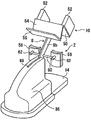
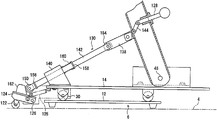
도 1은 본 발명에 따른 이승 장치의 일 실시형태를 나타내는 사시도.
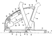
도 2는 도 1의 이승 장치에 있어서의 지지 암 및 이것에 관련되는 구성을 나타내는 도면.
도 3은 도 1의 이승 장치를 위에서 본 일부 단면도.
도 4는 도 1의 이승 장치에 있어서의 지지 회전판의 회전 기구를 나타내는 단면도.
도 5는 도 1의 이승 장치에 있어서의 지지 암 및 안전 커버 및 이들에 관련되는 구성을 나타내는 단면도.
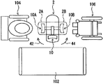
도 6은 도 1의 이승 장치의 사용 형태의 일례를 나타내는 간략도.
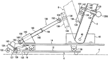
도 7은 이승 장치의 다른 실시형태에 있어서의 이동용 캐스터 및 이것에 관련되는 구성을 일부 단면으로 나타내는 단면도.
도 8은 도 7의 이승 장치에 있어서 조작 레버를 당겼을 때의 상태를 일부 단면으로 나타내는 단면도.
도 9는 도 7의 이승 장치에 있어서 지지 암을 들어올림 각도 위치로 요동한 상태를 일부 단면으로 나타내는 단면도.BRIEF DESCRIPTION OF THE DRAWINGS Fig. 1 is a perspective view showing an embodiment of a winch device according to the present invention; Fig.
Fig. 2 is a view showing a support arm in the winch device of Fig. 1 and a structure related thereto; Fig.
3 is a partial cross-sectional view of the Fig.
4 is a cross-sectional view showing a rotation mechanism of the support rotary plate in the winch device of Fig.
Fig. 5 is a cross-sectional view showing a support arm and a safety cover in the batting device of Fig. 1 and a configuration related thereto. Fig.
Fig. 6 is a schematic view showing an example of a usage form of the strapping device of Fig. 1; Fig.
Fig. 7 is a cross-sectional view showing, in partial cross-section, a movable castor according to another embodiment of the present invention and a structure related thereto; Fig.
Fig. 8 is a cross-sectional view showing, in partial cross section, a state when the operation lever is pulled in the winch device of Fig. 7; Fig.
9 is a cross-sectional view showing, in partial cross-section, a state in which the support arm is pivoted to the lifting angle position in the batting device of Fig.
이하, 첨부 도면을 참조하여 추가로 설명한다. 우선, 도 1~도 6을 참조하여, 본 발명에 따른 이승 장치의 일 실시형태에 대해서 설명한다.Hereinafter, the present invention will be further described with reference to the accompanying drawings. First, with reference to Figs. 1 to 6, an embodiment of a winch device according to the present invention will be described.
도 1~도 3에 있어서, 도시하는 이승 장치(2)(도 2 및 도 3에 있어서는, 후술하는 하우징을 생략하여 나타내고 있음)는 바닥면(4)에 설치되는 지지 구조체(6)와, 이 지지 구조체(6)에 요동이 자유롭게 장착된 지지 암(8)과, 이 지지 암(8)의 전단부에 부착된 상체 지지부(10)를 구비하고 있다.1 to 3, the illustrated winch device 2 (omitted from FIG. 2 and FIG. 3, which will be described later) includes a
도시하는 지지 구조체(6)는 바닥면에 고정적으로 설치되는 지지 본체(12)와, 이 지지 본체(12)에 회전이 자유롭게 지지된 지지 회전판(14)을 구비하고, 지지 회전판(14)의 전단부는 지지 본체(12)로부터 전방(도 2 및 도 3에 있어서 왼쪽)으로 뻗고, 또 그 후측부는 지지 본체(12)로부터 후방(도 2 및 도 3에 있어서 오른쪽)으로 뻗으며, 그 전단부보다 크게 뻗어 있다.The
지지 본체(12)는 플레이트 형상 부재로 구성되고, 이 형태에서는 정팔각형 형상으로 형성되어 있지만, 원형 형상, 직사각형 형상, 육각형 형상 등의 적당한 형상이면 된다. 이 지지 본체(12)의 바닥면에는 복수의 지지부(16)가 설치된다. 이들 지지부(16)는 예를 들면 고무 등으로 형성되고, 바닥면(4)에 고정적으로 설치된다.The support
지지 회전판(14)은 직사각형 형상의 플레이트 형상 부재로 구성되고, 도 4에 나타내는 바와 같이 지지 본체(12)에 회전이 자유롭게 지지된다. 지지 본체(12)의 중앙부에는 부착 부재(18)가 부착되고, 이 부착 부재(18)에 슬리브 부재(20)를 통하여 고정축(22)의 하단부가 지지되고, 고정축(22) 및 슬리브 부재(20)가 고정용 볼트(24)에 의해 부착 부재(18)에 고정되어 있다. 또, 지지 회전판(14)에는 지지 부착 슬리브(26)가 부착되고, 이 지지 부착 슬리브(26)가 한 쌍의 베어링(28)을 통하여 고정축(22)에 회전이 자유롭게 지지되어 있다. 이 지지 회전판(14)의 바닥면에는 둘레 방향으로 간격을 두고 복수(이 형태에서는, 정팔각형의 각부에 대응하여 8개)의 지지 캐스터(30)가 부착되어 있다. 지지 캐스터(30)는 임의의 방향으로 회동 가능한 것이며, 지지 회전판(14)의 전측부는 이들 지지 캐스터(30)를 통하여 지지 본체(12)에 지지된다.The
이 형태에서는 지지 회전판(14)의 후단부에 한 쌍의 후측 지지 캐스터(32)가 설치되어 있다. 후측 지지 캐스터(32)도 지지 캐스터(30)와 마찬가지로 임의의 방향으로 회동 가능한 것이다. 이와 같이 구성되어 있으므로, 지지 회전판(14)의 전측부는 지지 캐스터(30) 및 지지 본체(12)를 통하여 바닥면(4)에 지지되고, 지지 회전판(14)의 후측부는 후측 지지 캐스터(32)를 통하여 바닥면(4)에 지지된다.In this embodiment, a pair of rear supporting
이 형태에서는 지지 회전판(14)에 관련하여, 이것을 회동하기 위한 구동원(34)이 설치되고, 이 구동원(34)은 예를 들면 정역 회전 가능한 전동 모터로 구성된다. 구동원(34)으로부터의 구동력은 구동 전달 기구(36)를 통하여 지지 부착 슬리브(26)에 구동 전달된다. 도시하는 형태에서는, 구동 전달 기구(36)는 구동원(34)에 의해 회전 구동되는 웜 기어(38) 및 웜 휠(40)을 포함하고, 웜 기어(38) 및 웜 휠(40)이 맞물려, 웜 휠(40)이 지지 부착 슬리브(26)에 부착되어 있다. 이와 같이 구성되어 있으므로, 구동원(34)이 소정 방향으로 회전 구동되면, 구동 전달 기구(36)를 통하여 지지 회전판(14)이 예를 들면 화살표 42(도 6 참조)로 나타내는 방향으로 선회 이동되고, 또 구동원(34)이 소정 방향과 반대 방향으로 회전 구동되면, 구동 전달 기구(36)를 통하여 지지 회전판(14)이 예를 들면 화살표 44(도 6 참조)로 나타내는 방향으로 선회 이동된다. 이 형태에서는 지지 회전판(14)은 통상 도 6에 실선으로 나타내는 홈 각도 위치에 유지되고, 이 홈 각도 위치로부터 화살표 42로 나타내는 방향(도 6에 있어서 시계 방향)으로 90도 선회한 제1 선회 각도 위치와, 홈 각도 위치로부터 화살표 44로 나타내는 방향(도 6에 있어서 반시계 방향)으로 90도 선회한 제2 선회 각도 위치 사이를 선회 이동할 수 있다.In this embodiment, a
지지 암(8)은 지지 회전판(14)의 대략 중앙부에 전후 방향(도 2 및 도 3에 있어서 좌우 방향)으로 요동이 자유롭게 장착되어 있다. 지지 회전판(14)에는 한 쌍의 부착 브래킷(46)이 부착되고, 이러한 한 쌍의 부착 브래킷(46) 사이에 지지축(48)을 통하여 지지 암(8)의 하단부가 요동이 자유롭게 연결되어 있다. 지지 암(8)의 하부(8a)는 직선 형상으로 뻗고, 그 상부(8b)는 그 하부(8a)에 대하여 소정 각도 받아들임측(도 2 및 도 3에 있어서 오른쪽)으로 경사져 뻗어 있고, 그 경사 각도 α는 30~40도정도, 바람직하게는 33~37도로 하는 것이 바람직하고, 이러한 경사 각도로 설정함으로써, 하나의 관절점(즉, 지지축(48))으로써도 이승자(P)를 태운 상태에서 안정적으로 후술하는 바와 같이 이승시킬 수 있다.The
상체 지지부(10)는 이 지지 암(8)의 선단부에 설치되어 있다. 도시하는 상체 지지부(10)는 평평한 본체 지지부(50)를 구비하고, 이 본체 지지부(50)의 상면측에 이승자(P)의 상체가 받아들여져 지지된다. 본체 지지부(50)의 양단부에는 상방으로 돌출하는 돌출 지지부(52)가 설치되고, 한 쌍의 돌출 지지부(52)로써도, 이승자(P)의 양 겨드랑이로부터 양 팔의 부위가 지지된다. 이 형태에서는 또한 지지 본체부(50)의 전단부에는 대략 L자 형상으로 뻗는 전측 지지부(54)가 설치되고, 이 전측 지지부(54)의 전측부(56)에 양 손의 팔꿈치로부터 앞의 부분이 지지되고, 이러한 구성의 상체 지지부(10)로써도 이승자(P)를 지지함으로써, 안정된 상태로 지지할 수 있고, 이승할 때의 이승자(P)의 불안을 해소할 수 있다.The upper
지지 암(8)의 양측에는 이승자(P)의 양 무릎을 맞닿음 지지시키기 위한 한 쌍의 무릎 접촉 지지부(58)가 설치되어 있다. 이 형태에서는 지지 암(8)을 관통하여 부착축(60)이 설치되고, 이 부착축(60)의 일단부에 일방의 무릎 접촉 지지부(58)가 부착 부재(62)를 통하여 부착되고, 또 그 타단부에 타방의 무릎 접촉 지지부(58)가 부착 부재(62)를 통하여 부착되어 있다. 부착 부재(62)에 대해서는, 길이 조정이 자유롭게 하고, 무릎 접촉 지지부(58)의 전후 방향(도 2 및 도 3에 있어서 좌우 방향)의 위치를 이승자(P)의 체격 등에 따라서 위치 조정이 자유롭게 할 수 있다. 또한, 이승자(P)가 접촉하는 부위, 즉 무릎 접촉 지지부(58)의 표면 및 상체 지지부(10)의 지지 본체부(50)의 표면, 돌출 지지부(52)의 표면 및 전측 지지부(54)의 표면에 유연 재료를 배열설치하는 것이 바람직하다.On both sides of the
이 이승 장치(2)에서는, 지지 회전판(14)과 지지 암(8) 사이에, 지지 암(8)을 요동시키기 위한 신축 기구(64)가 개재되어 있다. 신축 기구(64)의 본체부(66)가 연결 핀(68)을 통하여 지지 회전판(14)측(구체적으로는, 지지 회전판(14)에 부착된 연결 브래킷(67))에 연결되고, 그 출력부(70)가 연결 핀(72)을 통하여 지지 암(8)측에 연결되어 있다. 도시하는 신축 기구(64)는 전동 모터(도시하지 않음)를 이용한 것으로 구성되고, 전동 모터가 소정 방향으로 회동되면, 본체부(66)에 대하여 출력부(70)가 신장되고, 또 전동 모터가 소정 방향과 반대 방향으로 회동되면, 본체부(66)에 대하여 출력부(70)가 수축된다. 이 신축 기구(64)로서는 전동 모터를 이용한 것 대신에, 예를 들면 압력 공기를 이용한 공압 실린더 기구 등을 사용하도록 해도 된다.In the win double-
이 형태에서는, 도 2에 나타내는 바와 같이, 신축 기구(64)가 신장되면, 지지 암(8)이 화살표 75로 나타내는 후측(도 2에 있어서 시계 방향)으로 요동되고, 도 2에 실선으로 나타내는 받아들임 각도 위치에 위치되고, 이 받아들임 각도 위치에 있어서 이승자(P)의 상체가 상체 지지부(10)에 후술하는 바와 같이 받아들여진다. 또, 신축 기구(64)가 수축되면, 지지 암(8)이 화살표 76으로 나타내는 전측(도 2에 있어서 반시계 방향)으로 요동되고, 도 2에 2점쇄선으로 나타내는 들어올림 각도 위치에 위치되고, 이승자(P)의 상체가 상체 지지부(10)에 받아들여져 지지된 상태에서 상방으로 들어올려진다.2, when the elongating and
지지 암(8)의 상기 서술한 요동에 관련하여, 상체 지지부(10)의 지지 본체부(50)를 다음과 같이 구성하는 것이 바람직하다. 도 2에 나타내는 바와 같이, 지지 암(8)이 상기 받아들임 각도 위치에 유지된 상태에 있어서는, 상체 지지부(10)의 지지 본체부(50)의 경사 각도 β1(수평 방향을 기준으로 하여 전방을 향하여 상방으로 경사진 각도)은 50~60도 정도, 바람직하게는 52~58도인 것이 바람직하고, 이러한 각도로 함으로써, 이승자(P)의 상체의 상체 지지부(10)로의 받아들임 지지가 용이하게 되고, 개호가 필요한 사람이라도 혼자서 상체 지지부(10)에 탈 수 있다. 또, 지지 암(8)이 상기 들어올림 각도 위치에 유지된 상태에 있어서는, 상체 지지부(10)의 지지 본체부(50)의 경사 각도 β2(수평 방향을 기준으로 하여 전방을 향하여 상방으로 경사진 각도)는 15~25도 정도, 바람직하게는 17~23도인 것이 바람직하고, 이러한 각도로 설정함으로써, 이승자(P)에게 불안감을 갖게 하지 않고 상방으로 들어올릴 수 있다. 그리고, 이와 같이 구성함으로써, 지지 암(8)의 요동 각도(즉, 받아들임 각도 위치와 들어올림 각도 위치 사이의 각도)는 받아들임 각도 위치에 있어서의 지지 본체부(50)의 경사 각도 β1과 들어올림 각도 위치에 있어서의 지지 본체부(50)의 경사 각도 β2의 경사 각도차(β1-β2)가 되고, 지지 암(8)은 이 각도 범위에 걸쳐 요동된다.Regarding the above-described rocking motion of the
이 형태에서는 지지 회전판(14)측(구체적으로는, 연결 브래킷(67))과 지지 암(8)측 사이에, 탄성 편의 수단으로서의 코일 스프링(74)이 개재되어 있다. 코일 스프링(74)의 일단측의 걸음부(76)가 연결 브래킷(67)의 걸음부(78)에 걸리고, 그 타단측의 걸음부(80)가 지지 암(8)의 걸음 브래킷(82)에 걸려 있다. 코일 스프링(74)은 지지 암(8)을 상기 들어올림 각도 위치를 향하여 탄성적으로 편의하고, 이와 같이 코일 스프링(74)을 설치함으로써, 이승자(P)를 싣고 지지한 상태에서 지지 암(8)을 상기 들어올림 각도 위치를 향하여 요동할 때에 신축 기구(64)에 작용하는 부하를 적게 할 수 있고, 그 결과, 소형의 능력이 작은 신축 기구(64)로도 지지 암(8)을 필요한 대로 요동시킬 수 있다. 또한, 신축 기구(64)에 작용하는 부하가 문제가 되지 않을 때에는, 이 탄성 편의 수단(코일 스프링(74))을 생략할 수도 있다.In this embodiment, a
이 이승 장치(2)에서는, 도 1에 나타내는 바와 같이, 지지 회전판(14)의 전측부, 지지 암(8)의 하부(8b), 신축 기구(64) 및 코일 스프링(74) 등(바꾸어 말하면, 지지 구조체(6)의 전측부)을 덮도록 하우징(86)이 설치되고, 이 하우징(86)은 지지 회전판(14)에 부착되고, 지지 회전판(14)과 일체적으로 회동한다.1, a front portion of the
하우징(86)에 관련하여, 다음과 같이 구성되어 있다. 도 1 및 도 5를 참조하여, 이 하우징(86)의 폭 방향 중앙부에는 그 상면으로부터 후면에 걸쳐 가늘고 긴 개구(88)가 설치되고, 지지 암(8)의 상부(8b)는 이 개구(88)를 통과하여 상방으로 뻗어 있다. 들어올림 각도 위치에 있을 때에는, 지지 암(8)은 하우징(86)의 개구(88)의 일단부에 위치하고, 또 받아들임 각도 위치에 있을 때에는, 지지 암(8)은 이 개구(88)의 타단측(이 형태에서는 하우징(86)의 상면으로부터 후면에 걸친 개구 부분)에 위치하고, 이 개구(88)의 범위 내에서 지지 암(8)이 요동한다.With respect to the
이 형태에서는 안전 커버(90)가 부착 나사(92)에 의해 지지 암(8)의 전면측에 부착되어 있다. 이 안전 커버(90)는 예를 들면 스프링강 등의 탄성을 가지는 플레이트로 구성되고, 하우징(86)의 상벽의 내측(즉, 개구(88)의 내측)에서 전방을 향하여 개구(88)를 따라 뻗고, 좌우의 하우징을 서로 조합시키기 위한 보스부(94)를 이용하며, 하우징(86)의 상벽과 이러한 보스부(94) 사이를 통과하여 뻗어 있다.In this embodiment, the
이와 같이 구성함으로써, 안전 커버(90)는 하우징(86)의 내측에서 개구(88)(이 개구(88)의 지지 암(8)보다 전측의 부분)를 막고, 지지 암(8)의 요동과 함께 이동하여 개구(88)를 막고, 이렇게 하여 이 개구(88)에 손가락 등이 삽입되어 하우징(86)과 지지 암(8) 사이에 끼이는 것을 방지하여, 사용상의 안전을 확보할 수 있다.The
이 이승 장치(2)는 예를 들면 다음과 같이 하여 사용된다. 주로 도 1, 도 2 및 도 6을 참조하여, 이 이승 장치(2)는 베드(102)의 횡측에 설치되고, 베드(102)로부터 간이 화장실(104)(예를 들면, 베드(102)의 횡측이며, 설치한 이승 장치(2)의 편측)로 옮길 때, 또 베드(102)로부터 휠체어(106)(예를 들면, 베드(102)의 횡측이며, 설치한 이승 장치(2)의 타측)로 옮길 때에 사용된다. 베드(102)로부터 예를 들면 간이 화장실(104)(또는 휠체어(106))로 옮길 때에는, 이승자(P)는 이승 장치(2)로 옮긴 후에 방향을 바꾸어 간이 화장실(104)(또는 휠체어(106))로 이승한다.This
예를 들면, 베드(102)로부터 이승 장치(2)로 옮길 때에는, 지지 암(8)은 도 2에 실선으로 나타내는 받아들임 각도 위치에 유지된다. 이러한 상태에서, 이승자(P)는 양 발을 지지 회전판(14)의 후측부(하우징(86)으로부터 후방으로 뻗어 있는 부위)에 싣고, 양 무릎을 무릎 접촉 지지부(58)에 맞닿게 하고, 이러한 상태에 있어서, 도 2에 나타내는 바와 같이, 상체 지지부(10)에 상체를 맡기고 그 지지 본체부(50)에 탄다. 이 때, 지지 본체부(50)의 경사 각도 β1이 50~60도이므로, 이승자(P)는 안심하고 상체 지지부(10)에 상체를 맡길 수 있다.For example, when moving from the
그리고, 지지 암(8)을 상방으로 들어올림 각도 위치를 향하여 요동시켜 상체를 들어올린다. 즉, 신축 기구(64)가 수축되어 지지 암(8)이 상기 받아들임 각도 위치로부터 도 2에 2점쇄선으로 나타내는 들어올림 각도 위치에 위치되고, 상체 지지부(10)에 맡겨져 실려 지지된 이승자(P)의 상체가 상방으로 들어올려진다. 이 때, 양 무릎이 무릎 접촉 지지부(58)에 맞닿은 상태에서 들어올려지므로, 양 발이 지지 회전판(14)에 실린 상태에서 들어올려지고, 따라서 이 양 발이 지지 회전판(14)으로부터 떨어져 떠오르지 않아, 이승자(P)의 자세가 무너지지 않고 들어올려진다. 이 들어올림 각도 위치를 향한 요동시에는 코일 스프링(74)의 탄성 편의력이 지지 암(8)에 작용하므로, 들어올려질 때에 신축 기구(64)에 작용하는 부하를 작게 할 수 있다.Then, the
지지 암(8)을 들어올림 각도 위치에 유지한 상태에 있어서는, 상체 지지부(10)의 지지 본체부(50)의 경사 각도 β2가 15~25도이므로, 이승자(P)는 앞으로 쓰러질 불안감을 가지지 않고 안심하고 그 상태를 유지할 수 있다.The inclination angle? 2 of the support
다음에, 구동원(34)을 작동시켜 이승 장치(2)의 지지 회전판(14)의 방향을 바꾸어 이승자(P)가 예를 들면 간이 화장실(104)측(또는 휠체어(106)측)에 위치하도록 선회시킨다. 구동원(34)이 소정 방향(또는 소정 방향에 대하여 반대 방향)으로 회동되고, 그러면 구동원(34)으로부터의 구동력이 구동 전달 기구(36)를 통하여 지지 회전판(14)에 전달되고, 이승자(P)가 탄 상태의 지지 회전판(14)이 화살표 42(또는 44)로 나타내는 방향으로 선회되고, 도 6에 실선으로 나타내는 홈 각도 위치로부터 도 6에 2점쇄선 2A(또는 2B)로 나타내는 제1 선회 각도 위치(또는 제2 선회 각도 위치)에 위치된다. 이 때, 지지 회전판(14)의 전측부측은 복수의 지지 캐스터(30)에 의해 지지되고, 그 후측부측은 한 쌍의 후측 지지 캐스터(32)에 의해 지지되어 있으므로, 지지 회전판(14)의 선회 이동을 원활하게 안정적으로 행할 수 있다.Next, the driving
그리고, 지지 암(8)을 하방으로 받아들임 각도 위치를 향하여 요동시켜 상체를 간이 화장실(104)(또는 휠체어(106))을 향하여 내린다. 즉, 신축 기구(64)가 신장되어 지지 암(8)이 상기 들어올림 각도 위치로부터 하방으로 요동되어 상기 받아들임 각도 위치에 위치되고, 상체 지지부(10)에 맡겨져 실려 지지되어 있던 이승자(P)의 상체가 하방으로 내려져, 이승자(P)는 간이 화장실(104)(또는 휠체어(106))의 전측에 위치하게 된다.Then, the
이와 같이 이동한 후, 이승자(P)는 상체 지지부(10)에 맡겨져 있던 상체를 상체 지지부(10)로부터 떼고, 양 발을 지지 회전판(14)으로부터 내려서 간이 화장실(104)(또는 휠체어(106))에 앉고, 이렇게 하여 베드(102)로부터 간이 화장실(104)(또는 휠체어(106))로 용이하게 이승할 수 있어, 개호가 필요한 사람이어도 혼자서 이동할 수 있다.After moving as described above, the occupant P removes the upper body held in the upper
이 이승 장치(2)에서는 지지 암(8)을 요동시키기 위해서 신축 기구(64)를 사용하고, 또 지지 회전판(14)을 선회 이동시키기 위해서 구동원(34)을 사용하고 있으므로, 이승자(P)가 조작 유닛(도시하지 않음)을 입력 조작하여 상기 서술한 이승 동작을 혼자서 행하도록 구성할 수 있다. 이러한 경우, 조작 유닛을 상체 지지부(10)에 설치하도록 하면 되고, 이와 같이 구성함으로써, 이승자(P)에 의한 입력 조작이 용이하게 되어, 예를 들면 베드(102)로부터 간이 화장실(104)(또는 휠체어(106))로 혼자서 간단히 이승하는 것이 가능하게 된다.In this win /
이러한 이승 장치는 바닥면에 고정적으로 설치하여 사용되는데, 설치 장소를 변경하는 경우도 있어, 이러한 경우, 그 이동을 용이하게 행할 수 있도록, 예를 들면 도 7~도 9에 나타내는 바와 같이 구성하는 것이 바람직하고, 이 밖의 실시형태의 이승 장치에 있어서는, 이승 장치를 이동시키기 위한 이동용 캐스터가 설치되어 있다. 또한, 이 밖의 실시형태에 있어서, 상기 서술한 실시형태와 실질상 동일 부재에는 동일 참조 번호를 붙이고, 그 설명을 생략한다.Such a win-win device is used by being fixedly installed on a floor surface. In some cases, the installation place is changed. In such a case, in order to facilitate the movement, for example, In the duplexer according to the other embodiments, a movable castor for moving the duplexer is provided. In the other embodiments, the same reference numerals are assigned to substantially the same members as those in the above-described embodiment, and a description thereof will be omitted.
도 7~도 9에 있어서, 이 밖의 형태의 이승 장치에 있어서는, 지지 회전판(14)의 전단부에 이동용 캐스터(122)가 배열설치되고, 이 이동용 캐스터(122)가 지지 구조체(6)의 지지 본체(12)로부터 하방으로 돌출되어 바닥면(4)에 작용하는 돌출 위치(도 9에 나타내는 위치)와, 바닥면(4)으로부터 상방으로 후퇴하는 후퇴 위치(도 7 및 도 8에 나타내는 위치) 사이를 이동이 자유롭게 설치되어 있다. 이 형태에서는 요동 부착 부재(124)가 지지 회전판(14)에 지지 핀(126)을 통하여 요동이 자유롭게 장착되고, 이 요동 부착 부재(124)의 전측부 하면에 이동용 캐스터(122)가 부착되어 있다. 또, 이 요동 부착 부재(124)와 지지 회전판(14) 사이에는 탄성 편의 수단으로서의 코일 스프링(125)이 개재되고, 이 코일 스프링(125)의 일단측이 요동 부착 부재(124)의 걸음 핀(127)에 걸리고, 그 타단측이 지지 회전판(14)의 걸음 로드(129)에 걸려 있다. 이 코일 스프링(125)은 이동용 캐스터(122)를 상기 후퇴 위치를 향하여 탄성적으로 편의하고, 이것에 의해, 이 이동용 캐스터(122)는 통상 상기 후퇴 위치에 유지된다. 또한, 이 이동용 캐스터(122)는 도 7~도 9에 나타내는 바와 같이 1개 설치하도록 해도 되고, 또는 복수 설치하도록 해도 된다.7 to 9, in the winch device of another type, a
이 이동용 캐스터(122)에 관련하여, 이 이동용 캐스터(122)의 상태를 바꾸기 위한 조작 레버(128) 및 조작 레버(128)의 전환 조작을 이동용 캐스터(122)에 전달하기 위한 입력 조작 전달 기구(130)가 설치되어 있다. 조작 레버(128)는 지지 암(8)의 하부(8a)에 장착된 유지 슬리브(132)에 이동이 자유롭게 지지되고, 도 7에 나타내는 삽입 위치와 도 8 및 도 9에 나타내는 인출 위치 사이를 이동이 자유롭다.An
입력 조작 전달 기구(130)는 지지 암(8)에 장착된 부착 브래킷(134)에 핀(136)을 통하여 선회가 자유롭게 연결된 누름 부재(138)와, 지지 회전판(14)의 전단부에 부착된 지지 브래킷(140)에 이동이 자유롭게 지지된 이동 로드(142)를 포함하고 있다. 누름 부재(138)의 일단부에는 반원 형상의 누름부(139)가 설치되어 있고, 이 누름 부재(138)의 타단부는 핀(142)을 통하여 중간 링크(144)에 회동이 자유롭게 연결되고, 그 중간 링크(144)는 핀(146)을 통하여 조작 레버(128)의 선단부에 회동이 자유롭게 연결되어 있다.The input
이와 같이 구성되어 있으므로, 조작 레버(128)를 누름 조작하여 상기 삽입 위치에 위치시키면, 도 7에 실선으로 나타내는 바와 같이, 중간 링크(144)를 통하여 누름 부재(138)가 핀(136)을 중심으로 하여 하방(도 7에 있어서 반시계 방향)으로 회동되어 비작용 위치에 유지된다. 이 비작용 위치에 있어서는, 누름 부재(138)가 지지 암(8)을 따라 뻗고, 지지 암(8)을 받아들임 각도 위치(도 7에 실선으로 나타내는 각도 위치)로부터 들어올림 각도 위치(도 7에 2점쇄선으로 나타내는 각도 위치)로 요동시켜도 이 누름 부재(138)의 누름부(139)가 이동 로드(142)에 작용하지는 않는다. 한편, 조작 레버(128)를 당겨 조작하여 상기 인출 위치에 위치시키면, 도 8에 나타내는 바와 같이, 중간 링크(144)를 통하여 누름 부재(138)가 핀(136)을 중심으로 하여 상방(도 7 및 도 8에 있어서 시계 방향)으로 회동되어 작용 위치에 유지된다. 이 작용 위치에 있어서는, 누름 부재(138)는 지지 암(8)으로부터 전방으로 돌출되어 뻗고, 이러한 상태에 있어서 지지 암(8)을 받아들임 각도 위치(도 8에 나타내는 각도 위치)로부터 들어올림 각도 위치(도 9에 나타내는 각도 위치)로 요동시키면, 누름 부재(138)의 누름부(139)가 이동 로드(142)에 후술하는 바와 같이 작용한다.7, when the
이동 로드(142)의 일단부에는 지지축(148)이 장착되고, 이 지지축(148)에 제1 굴림대(150)가 회전이 자유롭게 부착되어 있다. 또, 이동 로드(142)의 타단부에는 지지축(152)이 장착되고, 이 지지축(152)에 제2 굴림대(154)가 회전이 자유롭게 부착되며, 누름 부재(138)의 누름부(139)가 이 제2 굴림대(154)를 누르도록 작용한다.A
이 이동 로드(142)의 일단측에는 걸음 링(156)이 장착되고, 그 타단측에 받이 링(158)이 장착되고, 지지 브래킷(140)과 받이 링(158) 사이에 이 이동 로드(142)를 끼워 코일 스프링(160)이 개재되어 있다. 이 코일 스프링(160)은 받이 링(158)을 지지 암(8)측을 향하여 탄성적으로 편의하고, 이것에 의해, 이동 로드(142)는 걸음 링(156)이 지지 브래킷(140)에 맞닿는 상승 위치(도 7 및 도 8에 나타내는 위치)에 유지된다. 이 상승 위치에 있어서는, 이동 로드(142)가 상방으로 이동한 상태로 유지되므로, 이동 로드(142)의 제1 굴림대(150)가 요동 부착 부재(124)에 설치된 돌기부(162)에 작용하지는 않고, 이 돌기부(162)로부터 이격되는 상태로 유지된다. 이 밖의 실시형태에 있어서의 그 밖의 구성은, 도 1~도 6에 나타내는 실시형태와 실질상 동일하다.A moving
이승 장치를 다른 설치 장소로 이동하기 위해서는, 조작 레버(128)의 조작부(128G)를 당겨 조작하여 인출 위치에 위치시키고, 이러한 상태에서 지지 암(8)을 받아들임 각도 위치로부터 들어올림 각도 위치로 요동시키면 된다. 조작 레버(128)를 당겨 조작하여 상기 인출 위치에 위치시키면, 도 8에 나타내는 바와 같이, 중간 링크(144)를 통하여 누름 부재(138)가 작용 위치에 유지된다.In order to move the win double-throw device to another installation place, the
그리고, 이 상태에 있어서 지지 암(8)을 받아들임 각도 위치로부터 들어올림 각도 위치까지 요동하면, 도 9에 나타내는 바와 같이, 누름 부재(138)의 누름부(139)가 이동 로드(142)의 제2 굴림대(154)에 작용하고, 이 이동 로드(142)가 코일 스프링(160)의 탄성 편의력에 저항하여 전방측(도 9에 있어서 좌측 하방)으로 압압 이동된다. 이와 같이 이동 로드(142)가 이동되면, 이동 로드(142)의 제1 굴림대(150)가 요동 부착 부재(124)의 돌기부(162)에 작용하고, 이 요동 부착 부재(124) 및 이동용 캐스터(122)가 코일 스프링(125)의 탄성 편의력에 저항하여 하방으로 선회되어 돌출 위치에 위치된다.9, the pushing
이 돌출 위치에 위치된 상태에 있어서는, 도 9에 나타내는 바와 같이, 이동용 캐스터(122)가 지지 본체(12)로부터 하방으로 돌출하고, 전측에 있어서는 이 이동용 캐스터(122)가 바닥면(4)에 작용하고, 후측에 있어서는 한 쌍의 후측 지지 캐스터(도 2, 도 3 및 도 5에 있어서의 후측 지지 캐스터(32))가 바닥면(4)에 작용한다. 따라서, 이동용 캐스터(122) 및 후측 지지 캐스터를 사용하여 이승 장치를 용이하게 이동시킬 수 있다.The
이동용 캐스터(122)를 수납할 때에는, 지지 암(8)을 들어올림 각도 위치로부터 받아들임 각도 위치로 요동하고, 그 후 조작 레버(128)를 밀어 조작하면 된다. 지지 암(8)을 받아들임 각도 위치로 요동하면, 도 8로부터 이해되는 바와 같이, 지지 암(8)측의 누름 부재(138)와 이동 로드(142)의 제2 굴림대(154)의 압압 상태가 해제되고, 요동 부착 부재(124) 및 이동용 캐스터(122)가 코일 스프링(125)의 탄성 편의력에 의해 상방으로 선회되어 후퇴 위치에 위치됨과 아울러, 이동 로드(142)가 코일 스프링(160)의 탄성 편의력에 의해 지지 암(8)측으로 이동되어 상승 위치에 위치된다.When housing the
그리고, 조작 레버(128)를 밀어 조작하면, 조작 레버(128)가 삽입 위치에 위치되고, 누름 부재(138)가 비작용 위치에 유지되어, 이렇게 하여 이동용 캐스터(122)를 수납 상태로 할 수 있다.When the
이상, 본 발명에 따른 이승 장치의 실시형태에 대해서 설명했는데, 본 발명은 이러한 실시형태에 한정되는 것은 아니며, 본 발명의 범위를 일탈하지 않고 각종 변경 내지 수정이 가능하다.Although the embodiments of the present invention have been described above, the present invention is not limited to these embodiments, and various changes and modifications can be made without departing from the scope of the present invention.
2…이승 장치
6…지지 구조체
8…지지 암
10…상체 지지부
12…지지 본체
14…지지 회전판
58…무릎 접촉 지지부
64…신축 기구
74…코일 스프링(탄성 편의 수단)
90…안전 커버
102…베드
104…간이 화장실
106…휠체어
122…이동용 캐스터
128…조작 레버
130…입력 조작 전달 기구
138…누름 부재
142…이동 로드
P…이승자2… Winner
6 ... Support structure
8… Support arm
10 ... Upper body support
12 ... The support body
14 ... Support spindle
58 ... Knee contact support
64 ... Stretching mechanism
74 ... Coil spring (elastic means)
90 ... Safety cover
102 ... Bed
104 ... Toilet
106 ... bathchair
122 ... Movable casters
128 ... joystick
130 ... Input operation transmitting mechanism
138 ... The pressing member
142 ... Moving rod
P ... A winner
Claims (12)
이승할 때에는, 상기 지지 암이 상기 받아들임 각도 위치에 위치되고, 상기 받아들임 각도 위치에 있는 상기 지지 암의 상기 상체 지지부에 이승자의 상체가 받아들여지고, 그 후 상기 지지 암이 상기 받아들임 각도 위치로부터 상기 들어올림 각도 위치로 요동되어 이승자를 들어올리는 것을 특징으로 하는 이승 장치.A support arm mounted on the support structure so as to freely rock between an acceptance angular position for accepting the upper body of the occupant and a lifting angle position for lifting the upper body; And an upper body supporting portion, the upper portion of the supporting arm being inclined to the receiving side with respect to the lower portion,
And when the support arm is positioned at the acceptance angular position, the upper body of the occupant is received in the upper body support of the support arm at the acceptance angular position, Up position to raise the occupant.
Applications Claiming Priority (3)
| Application Number | Priority Date | Filing Date | Title |
|---|---|---|---|
| JP2011220327A JP5278860B2 (en) | 2011-10-04 | 2011-10-04 | Self-supporting transfer device |
| JPJP-P-2011-220327 | 2011-10-04 | ||
| PCT/JP2012/075325 WO2013051492A1 (en) | 2011-10-04 | 2012-10-01 | Transfer device |
Publications (2)
| Publication Number | Publication Date |
|---|---|
| KR20140077149A true KR20140077149A (en) | 2014-06-23 |
| KR102014528B1 KR102014528B1 (en) | 2019-08-26 |
Family
ID=48043651
Family Applications (1)
| Application Number | Title | Priority Date | Filing Date |
|---|---|---|---|
| KR1020147006181A Expired - Fee Related KR102014528B1 (en) | 2011-10-04 | 2012-10-01 | Transfer device |
Country Status (5)
| Country | Link |
|---|---|
| JP (1) | JP5278860B2 (en) |
| KR (1) | KR102014528B1 (en) |
| CN (1) | CN103501746B (en) |
| SG (1) | SG11201401281RA (en) |
| WO (1) | WO2013051492A1 (en) |
Cited By (2)
| Publication number | Priority date | Publication date | Assignee | Title |
|---|---|---|---|---|
| WO2016182324A1 (en) * | 2015-05-12 | 2016-11-17 | 현대중공업 주식회사 | Aid robot for transporting |
| KR20200043478A (en) * | 2017-12-06 | 2020-04-27 | 가부시키가이샤 후지 | A commercial device |
Families Citing this family (19)
| Publication number | Priority date | Publication date | Assignee | Title |
|---|---|---|---|---|
| JP2016165313A (en) * | 2013-07-11 | 2016-09-15 | 共栄プロセス株式会社 | Human body transfer device |
| JP6257462B2 (en) * | 2014-06-30 | 2018-01-10 | 株式会社ミツバ | Electric transfer machine |
| CN104161628B (en) * | 2014-08-14 | 2016-08-24 | 太仓市康辉科技发展有限公司 | A kind of folding moving vehicle |
| JP6587444B2 (en) * | 2015-07-17 | 2019-10-09 | 大和ハウス工業株式会社 | Transfer support device |
| WO2017014134A1 (en) * | 2015-07-17 | 2017-01-26 | 大和ハウス工業株式会社 | Transfer assistance device |
| WO2017199349A1 (en) * | 2016-05-17 | 2017-11-23 | 富士機械製造株式会社 | Assisting device |
| JP6715533B2 (en) * | 2016-12-06 | 2020-07-01 | 株式会社アートプラン | Transfer device |
| WO2018167856A1 (en) * | 2017-03-14 | 2018-09-20 | 株式会社Fuji | Aid device |
| DE102017109876A1 (en) * | 2017-05-08 | 2018-11-08 | Leonair Gmbh | Transfer aid for people with low trunk stability |
| JP7451417B2 (en) * | 2018-10-04 | 2024-03-18 | 株式会社Fuji | Assistive device |
| US12150907B2 (en) * | 2018-12-17 | 2024-11-26 | Hapai Transfer Systems Limited | Patient moving device |
| CN109498320A (en) * | 2018-12-28 | 2019-03-22 | 北京星和众工设备技术股份有限公司 | One kind shouldering formula shifting machine |
| CN109498321A (en) * | 2018-12-28 | 2019-03-22 | 北京星和众工设备技术股份有限公司 | Assist manned shifting machine |
| CN109512612B (en) * | 2019-01-07 | 2023-10-27 | 中国科学院沈阳自动化研究所 | Waist lifting joint of wounded robotics suitable for narrow space |
| JP6617997B1 (en) * | 2019-07-03 | 2019-12-11 | 有限会社工房Ryo | Transfer device |
| JP7213999B2 (en) | 2019-09-12 | 2023-01-27 | 株式会社Fuji | assistive device |
| IL272607B2 (en) * | 2020-02-11 | 2025-07-01 | Chayot Hedva | Lifting device to assist people with disabilities |
| JP7462887B2 (en) * | 2020-04-30 | 2024-04-08 | 矢崎化工株式会社 | Transfer Device |
| KR102577401B1 (en) * | 2021-09-27 | 2023-09-12 | 안왕근 | Rehabilitation equipment for spine and knee |
Citations (5)
| Publication number | Priority date | Publication date | Assignee | Title |
|---|---|---|---|---|
| JPH10192346A (en) | 1997-01-10 | 1998-07-28 | Matsushita Electric Ind Co Ltd | Transfer machine |
| US6119287A (en) * | 1998-05-29 | 2000-09-19 | Phillips; Barry S. | Lift and transfer apparatus for a disabled person |
| JP2002065766A (en) * | 2000-09-01 | 2002-03-05 | Paramount Bed Co Ltd | Manual stand-up lift |
| JP2010279491A (en) * | 2009-06-03 | 2010-12-16 | Toyama Univ | Human body gripping tool and transfer support device using the same |
| JP2011078535A (en) * | 2009-10-06 | 2011-04-21 | Muroto Tekkosho:Kk | Rising assisting device |
Family Cites Families (14)
| Publication number | Priority date | Publication date | Assignee | Title |
|---|---|---|---|---|
| JPS622027Y2 (en) * | 1984-11-09 | 1987-01-19 | ||
| GB9212055D0 (en) * | 1992-06-06 | 1992-07-22 | Arjo Mecanaids | Invalid hoist |
| JPH078287B2 (en) * | 1993-03-05 | 1995-02-01 | パラマウントベッド株式会社 | Mobile nursing lift |
| JPH0833678A (en) * | 1994-07-25 | 1996-02-06 | Iura:Kk | Elevating/lowering device in stretcher for patient transfer |
| JP2746296B2 (en) * | 1995-05-15 | 1998-05-06 | パラマウントベッド株式会社 | Link structure of floor operation mechanism in bed etc. |
| JP2000084001A (en) * | 1998-09-16 | 2000-03-28 | Hitachi Chem Co Ltd | Standing-up assisting device |
| JP2000135243A (en) * | 1998-10-29 | 2000-05-16 | Hiroshi Takei | Standing assisting chair |
| JP2000166977A (en) * | 1998-12-02 | 2000-06-20 | Masaya Tatsuno | Wheelchair with separating and uniting type transfer function |
| JP2000296154A (en) * | 1999-04-15 | 2000-10-24 | Tokuji Shibahara | Pickaback type caring apparatus |
| JP2003260087A (en) * | 2002-03-07 | 2003-09-16 | Aisan Ind Co Ltd | Electric foot rest for wheel chair |
| JP4247341B2 (en) * | 2002-06-19 | 2009-04-02 | 独立行政法人科学技術振興機構 | Rotation transfer type automatic assistance device |
| JP4630119B2 (en) * | 2005-04-28 | 2011-02-09 | 株式会社リコー | Transfer support device |
| CN101568317A (en) * | 2007-03-28 | 2009-10-28 | 松下电器产业株式会社 | Transfer assistance device and transfer assistance device with multi-supporter mechanism |
| JPWO2008129847A1 (en) * | 2007-04-12 | 2010-07-22 | パナソニック株式会社 | Transfer support device |
-
2011
- 2011-10-04 JP JP2011220327A patent/JP5278860B2/en not_active Expired - Fee Related
-
2012
- 2012-10-01 KR KR1020147006181A patent/KR102014528B1/en not_active Expired - Fee Related
- 2012-10-01 CN CN201280021108.8A patent/CN103501746B/en not_active Expired - Fee Related
- 2012-10-01 SG SG11201401281RA patent/SG11201401281RA/en unknown
- 2012-10-01 WO PCT/JP2012/075325 patent/WO2013051492A1/en not_active Ceased
Patent Citations (5)
| Publication number | Priority date | Publication date | Assignee | Title |
|---|---|---|---|---|
| JPH10192346A (en) | 1997-01-10 | 1998-07-28 | Matsushita Electric Ind Co Ltd | Transfer machine |
| US6119287A (en) * | 1998-05-29 | 2000-09-19 | Phillips; Barry S. | Lift and transfer apparatus for a disabled person |
| JP2002065766A (en) * | 2000-09-01 | 2002-03-05 | Paramount Bed Co Ltd | Manual stand-up lift |
| JP2010279491A (en) * | 2009-06-03 | 2010-12-16 | Toyama Univ | Human body gripping tool and transfer support device using the same |
| JP2011078535A (en) * | 2009-10-06 | 2011-04-21 | Muroto Tekkosho:Kk | Rising assisting device |
Cited By (3)
| Publication number | Priority date | Publication date | Assignee | Title |
|---|---|---|---|---|
| WO2016182324A1 (en) * | 2015-05-12 | 2016-11-17 | 현대중공업 주식회사 | Aid robot for transporting |
| KR20200043478A (en) * | 2017-12-06 | 2020-04-27 | 가부시키가이샤 후지 | A commercial device |
| KR20200043477A (en) * | 2017-12-06 | 2020-04-27 | 가부시키가이샤 후지 | A commercial device |
Also Published As
| Publication number | Publication date |
|---|---|
| CN103501746B (en) | 2016-08-17 |
| KR102014528B1 (en) | 2019-08-26 |
| WO2013051492A1 (en) | 2013-04-11 |
| SG11201401281RA (en) | 2014-08-28 |
| JP5278860B2 (en) | 2013-09-04 |
| JP2013078482A (en) | 2013-05-02 |
| CN103501746A (en) | 2014-01-08 |
Similar Documents
| Publication | Publication Date | Title |
|---|---|---|
| KR20140077149A (en) | Transfer device | |
| JP5789464B2 (en) | wheelchair | |
| CN102596140B (en) | Wheelchair and bed | |
| EP3721850B1 (en) | Aid device | |
| CN109152688B (en) | Transfer device | |
| KR20000068021A (en) | Wheelchair | |
| JP2016518215A (en) | Method and apparatus for moving a hospital bed or other wheeled object | |
| CA3115078C (en) | Assistance apparatus | |
| JP4304740B2 (en) | bed | |
| JP2006204606A (en) | Wheelchair | |
| JP2000325405A (en) | Back lifter for erectable bed | |
| JP2005103033A (en) | Standing-up assisting apparatus | |
| JP2829593B2 (en) | Handrail device in bed | |
| JP2000288033A (en) | Brake device for wheelchair or walking aid | |
| JP2004209220A (en) | Foldable wheelchair and lifting device therefor | |
| JPH0711649Y2 (en) | Operation device for footrest in chair | |
| JP2005152559A (en) | Footrest apparatus for wheelchair | |
| JP2001145670A (en) | Foldable wheelchair | |
| JPWO2018179294A1 (en) | Assistance device | |
| JPH07289592A (en) | Reclining bed | |
| JP2006000601A (en) | Walk support machine with function adaptable to inclination | |
| JPH0329654A (en) | Bed | |
| HK1259976B (en) | Transfer device | |
| HK1259976A1 (en) | Transfer device | |
| JP2000210342A (en) | Motor-driven travelling legless chair |
Legal Events
| Date | Code | Title | Description |
|---|---|---|---|
| PA0105 | International application |
St.27 status event code: A-0-1-A10-A15-nap-PA0105 |
|
| E13-X000 | Pre-grant limitation requested |
St.27 status event code: A-2-3-E10-E13-lim-X000 |
|
| P11-X000 | Amendment of application requested |
St.27 status event code: A-2-2-P10-P11-nap-X000 |
|
| P13-X000 | Application amended |
St.27 status event code: A-2-2-P10-P13-nap-X000 |
|
| PG1501 | Laying open of application |
St.27 status event code: A-1-1-Q10-Q12-nap-PG1501 |
|
| A201 | Request for examination | ||
| PA0201 | Request for examination |
St.27 status event code: A-1-2-D10-D11-exm-PA0201 |
|
| R17-X000 | Change to representative recorded |
St.27 status event code: A-3-3-R10-R17-oth-X000 |
|
| D13-X000 | Search requested |
St.27 status event code: A-1-2-D10-D13-srh-X000 |
|
| D14-X000 | Search report completed |
St.27 status event code: A-1-2-D10-D14-srh-X000 |
|
| E902 | Notification of reason for refusal | ||
| PE0902 | Notice of grounds for rejection |
St.27 status event code: A-1-2-D10-D21-exm-PE0902 |
|
| E13-X000 | Pre-grant limitation requested |
St.27 status event code: A-2-3-E10-E13-lim-X000 |
|
| P11-X000 | Amendment of application requested |
St.27 status event code: A-2-2-P10-P11-nap-X000 |
|
| P13-X000 | Application amended |
St.27 status event code: A-2-2-P10-P13-nap-X000 |
|
| E701 | Decision to grant or registration of patent right | ||
| PE0701 | Decision of registration |
St.27 status event code: A-1-2-D10-D22-exm-PE0701 |
|
| GRNT | Written decision to grant | ||
| PR0701 | Registration of establishment |
St.27 status event code: A-2-4-F10-F11-exm-PR0701 |
|
| PR1002 | Payment of registration fee |
St.27 status event code: A-2-2-U10-U12-oth-PR1002 Fee payment year number: 1 |
|
| PG1601 | Publication of registration |
St.27 status event code: A-4-4-Q10-Q13-nap-PG1601 |
|
| PN2301 | Change of applicant |
St.27 status event code: A-5-5-R10-R11-asn-PN2301 |
|
| PN2301 | Change of applicant |
St.27 status event code: A-5-5-R10-R14-asn-PN2301 |
|
| FPAY | Annual fee payment |
Payment date: 20220812 Year of fee payment: 4 |
|
| PR1001 | Payment of annual fee |
St.27 status event code: A-4-4-U10-U11-oth-PR1001 Fee payment year number: 4 |
|
| PC1903 | Unpaid annual fee |
St.27 status event code: A-4-4-U10-U13-oth-PC1903 Not in force date: 20230821 Payment event data comment text: Termination Category : DEFAULT_OF_REGISTRATION_FEE |
|
| PC1903 | Unpaid annual fee |
St.27 status event code: N-4-6-H10-H13-oth-PC1903 Ip right cessation event data comment text: Termination Category : DEFAULT_OF_REGISTRATION_FEE Not in force date: 20230821 |