KR20140077181A - A method of recovering a deposit from the sea bed - Google Patents
A method of recovering a deposit from the sea bed Download PDFInfo
- Publication number
- KR20140077181A KR20140077181A KR1020147010675A KR20147010675A KR20140077181A KR 20140077181 A KR20140077181 A KR 20140077181A KR 1020147010675 A KR1020147010675 A KR 1020147010675A KR 20147010675 A KR20147010675 A KR 20147010675A KR 20140077181 A KR20140077181 A KR 20140077181A
- Authority
- KR
- South Korea
- Prior art keywords
- suction
- moving
- vehicle
- watercraft
- grids
- Prior art date
- Legal status (The legal status is an assumption and is not a legal conclusion. Google has not performed a legal analysis and makes no representation as to the accuracy of the status listed.)
- Ceased
Links
Images






Classifications
-
- E—FIXED CONSTRUCTIONS
- E02—HYDRAULIC ENGINEERING; FOUNDATIONS; SOIL SHIFTING
- E02F—DREDGING; SOIL-SHIFTING
- E02F1/00—General working methods with dredgers or soil-shifting machines
-
- E—FIXED CONSTRUCTIONS
- E21—EARTH OR ROCK DRILLING; MINING
- E21C—MINING OR QUARRYING
- E21C50/00—Obtaining minerals from underwater, not otherwise provided for
-
- E—FIXED CONSTRUCTIONS
- E02—HYDRAULIC ENGINEERING; FOUNDATIONS; SOIL SHIFTING
- E02F—DREDGING; SOIL-SHIFTING
- E02F3/00—Dredgers; Soil-shifting machines
- E02F3/04—Dredgers; Soil-shifting machines mechanically-driven
- E02F3/88—Dredgers; Soil-shifting machines mechanically-driven with arrangements acting by a sucking or forcing effect, e.g. suction dredgers
- E02F3/8833—Floating installations
-
- E—FIXED CONSTRUCTIONS
- E02—HYDRAULIC ENGINEERING; FOUNDATIONS; SOIL SHIFTING
- E02F—DREDGING; SOIL-SHIFTING
- E02F3/00—Dredgers; Soil-shifting machines
- E02F3/04—Dredgers; Soil-shifting machines mechanically-driven
- E02F3/88—Dredgers; Soil-shifting machines mechanically-driven with arrangements acting by a sucking or forcing effect, e.g. suction dredgers
- E02F3/8858—Submerged units
-
- E—FIXED CONSTRUCTIONS
- E02—HYDRAULIC ENGINEERING; FOUNDATIONS; SOIL SHIFTING
- E02F—DREDGING; SOIL-SHIFTING
- E02F3/00—Dredgers; Soil-shifting machines
- E02F3/04—Dredgers; Soil-shifting machines mechanically-driven
- E02F3/88—Dredgers; Soil-shifting machines mechanically-driven with arrangements acting by a sucking or forcing effect, e.g. suction dredgers
- E02F3/8858—Submerged units
- E02F3/8866—Submerged units self propelled
-
- E—FIXED CONSTRUCTIONS
- E02—HYDRAULIC ENGINEERING; FOUNDATIONS; SOIL SHIFTING
- E02F—DREDGING; SOIL-SHIFTING
- E02F3/00—Dredgers; Soil-shifting machines
- E02F3/04—Dredgers; Soil-shifting machines mechanically-driven
- E02F3/88—Dredgers; Soil-shifting machines mechanically-driven with arrangements acting by a sucking or forcing effect, e.g. suction dredgers
- E02F3/90—Component parts, e.g. arrangement or adaptation of pumps
- E02F3/907—Measuring or control devices, e.g. control units, detection means or sensors
-
- E—FIXED CONSTRUCTIONS
- E02—HYDRAULIC ENGINEERING; FOUNDATIONS; SOIL SHIFTING
- E02F—DREDGING; SOIL-SHIFTING
- E02F7/00—Equipment for conveying or separating excavated material
- E02F7/005—Equipment for conveying or separating excavated material conveying material from the underwater bottom
-
- E—FIXED CONSTRUCTIONS
- E02—HYDRAULIC ENGINEERING; FOUNDATIONS; SOIL SHIFTING
- E02F—DREDGING; SOIL-SHIFTING
- E02F3/00—Dredgers; Soil-shifting machines
- E02F3/04—Dredgers; Soil-shifting machines mechanically-driven
- E02F3/96—Dredgers; Soil-shifting machines mechanically-driven with arrangements for alternate or simultaneous use of different digging elements
Landscapes
- Engineering & Computer Science (AREA)
- Mining & Mineral Resources (AREA)
- Civil Engineering (AREA)
- General Engineering & Computer Science (AREA)
- Structural Engineering (AREA)
- Mechanical Engineering (AREA)
- Geochemistry & Mineralogy (AREA)
- General Life Sciences & Earth Sciences (AREA)
- Life Sciences & Earth Sciences (AREA)
- Geology (AREA)
- Drilling And Exploitation, And Mining Machines And Methods (AREA)
- Separation Of Solids By Using Liquids Or Pneumatic Power (AREA)
- Underground Or Underwater Handling Of Building Materials (AREA)
- Processing Of Solid Wastes (AREA)
- Cleaning Or Clearing Of The Surface Of Open Water (AREA)
- Toys (AREA)
- Refuse-Collection Vehicles (AREA)
- Manipulator (AREA)
Abstract
본 발명은 해저로부터 밧줄이 풀려진 수상선박(20) 및 해저를 이동해 퇴적물을 흡입하고 각각의 가요성 라이저(26;29)에 의해 수상선박에 각각 연결된 제 1 및 제 2 석션차량(27;30)을 이용해 해저로부터 퇴적물의 회수방법에 관한 것으로, 가요성 라이저를 따라 석션차량으로부터 수상선박까지 퇴적물 슬러리가 수송된다. 상기 방법은 석션차량들이 수상선박보다 실질적으로 더 멀리 이동하도록 복수의 레인들에서 해저를 가로질러 앞뒤로 제 1 및 제 2 석션차량을 이동시키고, 인접한 레인들 간에 실질적으로 간격 없이 퇴적물을 채광하기 위해 레인들이 서로 인접해 있는 식으로 각 레인의 끝에서 각 차량을 터닝 또는 후진시키는 단계를 포함한다. 석션차량만이 해저에 놓인다.The present invention relates to a water ship 20 from which a rope is released from the sea floor and first and second suction vehicles 27 and 30 connected to the watercraft by suction of sediments by the seabed and by respective flexible risers 26 ), A sediment slurry is transported from a suction vehicle to a water ship along a flexible riser. The method comprises moving the first and second suction vehicles back and forth across the seabed at a plurality of lanes so that the suction vehicles move substantially further than the watercraft, And turning each vehicle at the end of each lane in such a way that they are adjacent to each other. Only a suction vehicle is placed on the seabed.
Description
본 발명은 해저로부터 퇴적물의 회수방법에 관한 것이다.The present invention relates to a method for recovering sediments from the sea bed.
이를 실행하는 방법이 WO 2010/000289에 개시되어 있다. 이는 수상선박과 해저를 이동하는 석션차량을 포함한다. 석션차량은 가요성 라이저에 의해 수상선박에 부착되어 있고, 상기 가요성 라이저를 따라 석션차량으로부터 수상선박으로 퇴적물의 슬러리가 수송된다. A method of implementing this is disclosed in WO 2010/000289. This includes the watercraft and the suction vehicle that moves the seafloor. The suction vehicle is attached to the watercraft by a flexible riser and the slurry of sediment is transported from the suction vehicle to the watercraft along the flexible riser.
경제적으로 실행가능하기 위해, 생산공정은 가능한 한 효율적이어야 한다. 이는 최소의 가능한 비용으로 최고의 가능한 생산율이 구현되어야 하는 것을 의미한다. 펌핑 용량, 석션차량의 속도와 같은 많은 요인들이 생산율에 영향을 끼치나, 운영비는 에너지 비용에 의해 주로 결정된다.To be economically feasible, the production process should be as efficient as possible. This means that the highest possible production rate should be implemented with the least possible cost. Many factors, such as pumping capacity and speed of the suction vehicle, affect production rates, but operating costs are largely determined by energy costs.
수상선박에 대한 석션차량의 범위(즉, 수상선박으로부터 멀리 이동할 수 있는 수평거리)는 가요성 라이저의 길이에 의해 결정된다. 더 긴 가요성 라이저가 더 먼 범위를 제공하나, 이는 또한 석션차량의 무게 증가 및 또한 이동 및 조종시 석션차량에 대한 저항력과 관성력 제공과 같은 단점이 있다.The range of suction vehicles for the watercraft (ie, the horizontal distance that can be moved away from the watercraft) is determined by the length of the flexible risers. Longer flexing risers provide a greater range, but they also have drawbacks such as increasing the weight of the suction vehicle and also providing resistance and inertia to the suction vehicle during movement and steering.
퇴적물을 회수하는 가장 직접적인 방법은 석션차량이 단순히 단일 수로를 따라 각각 이동함으로써 수상선박을 뒤따르는 것이다. 그러나, 이런 환경 하에서, 석션차량은 수상 선박과 동일한 속도로 이동해야 한다. 이는 상대적으로 고속으로 물속을 지나며 라이저 시스템을 끌어당김으로써 안전성이 연루된다면 바람직하지 못하다. 이는 석션차량이 넘어지면 석션차량에 쉽게 손상을 줄 수 있다.The most direct way to retrieve sediments is to follow the water craft by simply moving the suction vehicle along a single waterway. Under such circumstances, however, the suction vehicle must travel at the same speed as the water craft. This is undesirable if safety is involved by attracting the riser system through water at relatively high speeds. This can easily damage the suction vehicle if the suction vehicle falls over.
“Data Gathering and Gap Analysis for Assessment of Cumulative Effects of Marine Diamond Mining Activities on the BCLME Region”(Project BEHP/CEA/03/02), Chapter 4: Mining Methods, 페이지 165-168; 2008년 3월 간행; 제목의 Benguela Current Large Marine Ecosystem Programme(www.bclme.org에서 구매가능)에 대한 Pisces Environmental Services(Pty)사의 보고서는 해저 채광용 해저 크롤러의 사용을 개시하고 있다. 그러나, 상기 차량은 차량을 조종하기 위한 조이스틱을 이용하는 운전자에 의해 움직여 진다. 그러면, 잘 정의된 패턴을 따르지 못하게 된다."Data Gathering and Gap Analysis for Assessment of Marine Diamond Mining Activities on the BCLME Region" (Project BEHP / CEA / 03/02), Chapter 4: Mining Methods, pages 165-168; Published in March 2008; The Pisces Environmental Services (Pty) report on the subject Benguela Current Large Marine Ecosystem Program (available at www.bclme.org) is launching the use of submarine submarine crawlers. However, the vehicle is driven by a driver using a joystick to steer the vehicle. Then you will not follow a well-defined pattern.
본 발명의 내용에 포함됨.Are included in the scope of the present invention.
본 발명에 따르면, 해저로부터 밧줄이 풀려진 수상선박 및 해저를 이동해 퇴적물을 흡입하고 각각의 가요성 라이저에 의해 수상선박에 각각 연결된 제 1 및 제 2 석션차량을 이용해 해저로부터 퇴적물의 회수방법으로서, 석션차량들이 수상선박보다 실질적으로 더 멀리 이동하도록 복수의 레인들에서 해저를 가로질러 앞뒤로 제 1 및 제 2 석션차량을 이동시키고, 인접한 레인들 간에 실질적으로 간격 없이 퇴적물을 채광하기 위해 레인들이 서로 인접해 있는 식으로 각 레인의 끝에서 각 차량을 터닝 또는 후진시키는 단계를 포함하고, 석션차량으로부터 수상선박까지 퇴적물 슬러리가 가요성 라이저를 따라 수송되는 해저로부터 퇴적물의 회수방법이 제공된다.According to the present invention, there is provided a method for recovering sediments from a seabed using a first and a second suction vehicle which are connected to a watercraft by suctioning sediments by moving the watercraft and undersea from which the rope is released, To move the first and second suction vehicles back and forth across the seabed from the plurality of lanes so that the suction vehicles move substantially farther away than the marine vessel and to allow the lanes to be adjacent to each other Wherein the sediment slurry is transported along a flexible riser from a suction vehicle to a water ship, wherein the slurry is transported along a flexible riser.
본 발명에서, 석션차량이 더 이상 수상선박의 속도와 맞출 필요가 없다. 또한, 인접한 레인들에서 해저를 채광함으로써, 해저 영역은 간격을 두지 않고도 커버되어질 수 있어, 작동 효율을 향상시킨다.In the present invention, the suction vehicle no longer needs to match the speed of the watercraft. In addition, by mining the seabed in adjacent lanes, the seabed area can be covered without spacing, improving the operating efficiency.
하나 이상의 석션차량을 이용하는 것은 동작의 연속성을 제공하는 점에서 이점적이다. 스페어 석션차량은 수상선박의 데크에 그대로 있을 수 있고, 만일 한 대의 석션차량이 고장나면, 다른 차량 또는 차량들이 계속 동작하는 동안 스페어 차량으로 교체될 수 있다. 정상동작이 진행중인 동안 회수된 차량은 이후 수리된다. 2대의 이런 차량들로 기술하였으나, 본 발명은 2 이상의 차량들에도 또한 적용될 수 있다.The use of more than one suction vehicle is advantageous in that it provides continuity of operation. Spare suction vehicles can remain on the deck of the watercraft, and if one suction car fails, they can be replaced with spare cars while other vehicles or vehicles continue to operate. The recovered vehicle is then repaired while normal operation is in progress. Although described with two such vehicles, the present invention may also be applied to two or more vehicles.
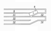
도 1a는 일단에 마우스가 있는 석션차량(1)을 도시한 것이다. 이는 제 1 레인(2)을 따라 이동한 후 터닝 서클(3)에서 180°로 터닝하고 제 2 레인(4)을 따라 복귀한다. 석션차량(1)은 다른 통로를 만드나 이 번은 제 3 레인(5)을 따라 제 2 터닝써클(6)로 이동한다. 도 1a에서 알 수 있는 바와 같이, 2개의 터닝 서클들(3,6) 사이에 상당한 중첩(7)이 있으며, 상기 터닝 서클들에서 석션차량의 시간 동작이 최적이지 않다. 도 1b는 어느 일단에 석션 마우스를 갖는 제 2 차량(8)을 도시하고 있다. 180°로 회전하는 대신, 차량(8)은 제 1 레인(9,10)의 끝에 도달한 다음 같은 방향을 여전히 바라보면서 인접 레인(11,12)으로 간단히 후진된다. 도 1b에서 명백한 바와 같이, 영역(13,14)을 석션차량이 놓쳐, 석션동작이 비효율적이게 된다. 그 결과, 회수 효율을 극대화하기 위해, 채광 패턴의 턴 회수가 최소화되어야 한다.1A shows a suction vehicle 1 having a mouse at one end thereof. Which travels along the
따라서, 바람직하기로, 상기 방법은 그리드의 제 1 끝단에서 제 2 끝단까지 길이방향으로 제 1 레인에 움직이는 차량에 의해 커버되는 제 1 그리드를 가로지르는 제 1 석션차량을 이동시키고, 제 1 레인에 인접한 레인을 따라 상기 제 1 레인의 길이방향으로 복귀하기 전에 약간의 측면으로 이동하며; 제 1 그리드를 마칠 때까지 매번 이전 레인 옆의 인접한 레인을 따라 두 끝단들 사이에서 이런 식으로 반복적으로 이동시키는 단계; 제 1 및 제 2 석션차량들 간의 측면 간격이 실질적으로 일정하게 내내 유지되도록 제 1 그리드 옆의 인접한 제 2 그리드에서도 동일한 방식으로 제 2 석션차량을 동시에 이동시키는 단계; 및 제 1 및 제 2 그리드를 마친 후, 제 1 및 제 2 그리드에 길이방향으로 각각 인접한 제 3 및 제 4 그리드로 제 1 및 제 2 석션차량을 이동시키고, 제 1 및 제 2 그리드와 동일한 방식으로 제 3 및 제 4 그리드를 커버하는 단계를 더 포함한다.Thus, preferably, the method comprises moving a first suction vehicle traversing a first grid covered by a vehicle moving in a first lane longitudinally from a first end to a second end of the grid, Moves slightly along the adjacent lane before returning in the longitudinal direction of the first lane; Repeatedly moving in this manner between the two ends along the adjacent lane next to the previous lane each time until the first grid is finished; Simultaneously moving the second suction vehicle in the same manner in the adjacent second grid next to the first grid so that the lateral spacing between the first and second suction vehicles is maintained substantially constant throughout; And after the first and second grids are finished, moving the first and second suction vehicles to the third and fourth grids respectively adjacent to the first and second grids respectively in the longitudinal direction, and in the same manner as the first and second grids To cover the third and fourth grids.
이는 제 1 및 제 2 차량이 실질적으로 일정한 거리로 떨어져 유지될 수 있고, 이로써 충돌 및 얽힘 가능성을 없애는 점에서 효율적인 채광패턴을 제공한다.This provides an efficient lightening pattern in that the first and second vehicles can be maintained at a substantially constant distance apart, thereby eliminating collision and entanglement possibilities.
두번째로, 석션차량들이 서로 옆에 인접한 제 1 및 제 2 그리드를 길이방향으로 이동하기 때문에, 라이저 길이의 이용이 최적화되어 레인들이 더 길어지게 됨으로써 석션차량들이 횡방향으로 이동하는 채광 패턴에 비해 효율을 향상시킬 수 있다.Secondly, since the suction vehicles move longitudinally adjacent first and second grids adjacent to each other, the utilization of the riser length is optimized and the lanes become longer, so that the suction vehicles are more efficient than the light- Can be improved.
수상선박은 단순히 길이방향으로 천천히 이동함으로써 석션차량들이 제 3 및 제 4 그리드를 이동하여 다른 그리드로 점차 이동함에 따라 석션차량과 보조를 유지할 수 있다. 그러나, 바람직하기로, 상기 방법은 석션차량이 제 1 및 제 2 그리드에 이동하는 동안 횡방향으로 수상선박을 이동시키고, 석션차량이 제 3 및 제 4 그리드로 이동함에 따라 길이방향으로 수상선박을 이동시키는 단계를 더 포함한다. 석션차량들이 그리드를 지날 때 수상선박이 옆으로 이동함으로써, 그리드의 폭은 임의의 주어진 라이저 길이에 대해 증가될 수 있다. 이는 더 짧은 라이저의 사용을 효과적으로 가능하게 한다. 석션차량들이 제 3 및 제 4 그리드로 이동함에 따라 수상선박이 길이방향으로 이동하기 때문에, 전반적으로 석션차량들은 수상선박이 일반적으로 한 그리드의 중간지점에서 대략 한 그리드의 길이인 인접 그리드의 중간지점까지 이동하는 동안 2개의 그리드의 길이를 효과적으로 이동하며 한 그리드의 일단에서 제 2 그리드의 타단까지 이동해야 하도록 석션차량들의 대략 절반 속도로 이동하는 것만이 필요하다. The watercraft can simply keep moving in the longitudinal direction to keep up with the suction vehicle as the suction vehicles move through the third and fourth grids and gradually move to another grid. Preferably, however, the method comprises moving the watercraft in a lateral direction while the suction vehicle is moving to the first and second grids, and moving the watercraft in the longitudinal direction as the suction vehicle moves to the third and fourth grid, Further comprising the steps of: As the watercraft moves sideways as the suction vehicles pass the grid, the width of the grid can be increased for any given riser length. This effectively enables the use of shorter risers. Since the watercraft moves in the longitudinal direction as the suction vehicles move to the third and fourth grids, the suction vehicles as a whole generally require that the watercraft be at the midpoint of the adjacent grid, generally the length of one grid, It is only necessary to move about half the speed of the suction vehicles so as to move the length of the two grids effectively while moving from one end of one grid to the other end of the second grid.
제 1 및 제 2 그리드의 끝단에 도달하면, 석션차량은 그런 후 이전 그리드를 커버했던 동일한 횡방향의 다음 그리드를 커버하기 시작하도록 그리드의 전체 폭을 가로질러 횡으로 이동될 수 있다. 그러나, 바람직하기로는, 각각의 제 3 및 제 4 그리드로부터 반대 횡방향으로 제 1 및 제 2 그리드에서 작은 측면 이동이 발생한다. 필연적으로, 이는 각 길이방향의 인접 그리드가 이전 그리드에 반대 횡방향으로 커버되는 것을 의미한다. 이는 더 효율적인 채광패턴을 제공하며 수상선박의 측면 이동이 더 적어지게 된다.Upon reaching the ends of the first and second grids, the suction vehicle can then be moved transversely across the entire width of the grid to begin covering the next transverse next grid that covered the previous grid. Preferably, however, small lateral displacements occur in the first and second grids from the respective third and fourth grids in the opposite transverse direction. Inevitably, this means that the adjacent grid in each longitudinal direction is covered in the transverse direction to the previous grid. This provides a more efficient mining pattern and less lateral movement of the water craft.
제 2 바람직한 패턴에 대해, 상기 방법은 바람직하게는 길이방향으로 수상선박을 이동시키고 횡방향으로 제 1 및 제 2 석션차량을 이동시키는 단계를 포함한다. 이런 패턴으로, 수상선박은 석션차량이 횡방향으로 이동함에 따라 훨씬 더 간단한 경로를 따라 이동할 수 있다. 이와 같이, 수상선박의 더 복잡한 컨트롤이 바람직하지 못한 것으로 고려되는 경우 이런 패턴이 이용될 수 있다. For the second preferred pattern, the method preferably comprises moving the watercraft in the longitudinal direction and moving the first and second suction vehicles in the lateral direction. With this pattern, the watercraft can move along a much simpler path as the suction vehicle moves in the lateral direction. As such, this pattern can be used if more complex control of the marine vessel is considered undesirable.
이런 패턴으로, 수상선박은 상기 수상선박의 일 측면에 각각의 석션차량을 이동시키는 단계를 더 포함할 수 있다. 대안으로, 상기 방법은 수상선박의 양 측면에 각각의 석션차량을 이동시키는 단계를 더 포함할 수 있다. 상기 수상선박의 일 측면에 각각의 석션차량을 이동시키는 단계는 2개의 석션차량들이 자신의 공간으로 각각 이동하는 이점이 있는 반면, 수상선박의 양 측면에 각각의 석션차량을 이동시키는 단계는 더 긴 레인들을 제공하고 이에 따라 턴 회수를 줄인다.In this pattern, the watercraft may further include moving each of the suction vehicles to one side of the watercraft. Alternatively, the method may further comprise moving each suction vehicle to both sides of the watercraft. The step of moving each suction vehicle to one side of the water ship has the advantage that the two suction vehicles each move to their own space while the step of moving each suction vehicle to both sides of the water ship is longer Provide lanes and thus reduce turn count.
제 3 바람직한 패턴에 대해, 상기 방법은 바람직하게는 가요성 라이저가 수상선박에 부착된 지점을 실질적으로 중심으로 한 아치형 경로에 제 1 및 제 2 석션차량을 이동시키는 단계를 더 포함한다. 이는 각 라이저의 "범위"가 실질적으로 일정하게 유지되고 또한 상기 횡배열보다 더 긴 레인을 가능하게 하는 이점이 있다. For the third preferred pattern, the method preferably further comprises moving the first and second suction vehicles to an arcuate path substantially centered about the point at which the flexible riser is attached to the water vessel. This has the advantage that the "extent" of each riser remains substantially constant and also enables longer lanes than the transverse arrangement.
다시, 상기 방법은 수상선박의 일 측면에 각각의 석션차량을 이동시키는 단계, 또는 수상선박의 양 측면에 각각의 석션차량을 이동시키는 단계를 더 포함할 수 있다.Again, the method may further include moving each suction vehicle to one side of the watercraft, or moving each suction vehicle to both sides of the watercraft.
각 석션차량은 일단에 마우스를 가질 수 있어, 이 경우 차량들이 실질적으로 늘 동일한 방향을 바라보면서 그리드의 끝단들 사이로 이동된다. 그러나, 바람직하기로, 상기 방법은 반대 끝으로 복귀하기 전에 레인의 끝에 도달할 때마다 실제로 180°로 각 석션차량을 터닝시키는 단계를 더 포함한다. 이 방법은 더 간단하고 더 저렴하며 더 가벼운 설계를 가질 수 있는 하나의 석션을 가진 차량에 이용될 수 있다. Each suction vehicle can have a mouse at one end, in which case the vehicles are moved substantially between the ends of the grid looking in the same direction. Preferably, however, the method further comprises the step of actually turning each suction vehicle to 180 ° each time it reaches the end of the lane before returning to the opposite end. This method can be used in vehicles with a single suction that can be simpler, cheaper and lighter in design.
본 발명의 내용에 포함됨.Are included in the scope of the present invention.
첨부도면을 참조로 본 발명에 따른 방법의 예들을 설명한다:
도 1a 및 도 1b는 수로 끝단에서 조우되는 문제들을 도시한 개략 평면도이다.
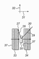
도 2는 회수 시스템의 개략 횡단면도이다.
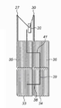
도 3a 내지 도 3d는 제 1 채광 패텅의 단계들을 도시한 개략 평면도이다.
도 4는 제 2 채광 패턴의 개략 평면도이다.
도 5는 제 2 채광 패턴의 변화에 대한 개략 평면도이다.
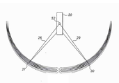
도 6은 제 3 채광 패턴의 변화에 대한 개략 평면도이다.Examples of methods according to the present invention are described with reference to the accompanying drawings:
Figures 1a and 1b are schematic plan views illustrating problems encountered at the end of a waterway.
Figure 2 is a schematic cross-sectional view of the recovery system.
3A to 3D are schematic plan views showing the steps of the first lighting pattern.
4 is a schematic plan view of the second lighting pattern.
5 is a schematic plan view showing a change in the second lighting pattern.
6 is a schematic plan view showing a change in the third light pattern.
펌핑 시스템(21)과 슬러리 처리시스템(22)이 설비된 수상선박(20)을 구비한 전체 시스템이 도 2에 도시되어 있다. 라이저 시스템은 부유탱크(24) 및 수상선박에 이르는 가요성 도관(25)에 의해 부분적으로 지지된 강체 라이저 번들(23)을 구비한다. 제 1 가요성 라이저(26)가 강체 라이저 번들(23)로부터 해저(28)를 가로질러 이동하는 제 1 석션차량(27)에 이르는 반면, 제 2 가요성 라이저(29)는 제 2 석션차량(30)에 이른다. 수상선박은 제자리에 머무르고 기설정된 트랙을 따르게 할 수 있는 동적 위치지정 시스템을 갖는다. An overall system with a
사용시, 석션차량은 위의 표면 퇴적물들을 흡입하며 해저를 이동하고, 그런 후 상기 퇴적물들은 강체 라이저 번들(23)과 가요성 도관(25)을 통해 수상선박으로 가요성 라이저(26,29)를 따라 펌핑되며, 상기 선박에서 퇴적물들은 가공공장(22)에서 가공된 다음 다른 공정을 위해 해안으로 운송된다. 폐수는 해저에 인접한 폐기용 라이저 시스템 아래로 펌프 시스템(21)에 의해 펌프된다. 이 적용은 채광 패턴의 특성과 관계 있는데 여기서 더 상세하게 설명하지 않을 것이다. 라이서 번들(23)의 상세한 설명을 위해, 계류중인 출원(대리인 문서번호 113711GB00)을 참조로 하며, 석션차량(27,30)은 출원(대리인 문서번호 113709GB00)에 기술되어 있다. 전체 시스템은 WO 2010/000289에 또한 개괄적으로 기술되어 있다. In use, the suction vehicle sucks up the surface sediments and moves the seabed, and the sediments are then conveyed to the water vessel through the
도 2에서, 횡방향은 화살표 31로 도시되어 있는 반면, 길이방향은 지면의 안쪽 및 바깥쪽 방향이다. 이는 도 3의 화살표 32에 도시되어 있다. In Fig. 2, the transverse direction is shown by the
도 3을 참조로 채광패턴을 설명한다. 먼저 도 3d를 참조하면, 채광패턴은 제 1 그리드(33), 제 2 그리드(34), 제 3 그리드(35), 및 제 4 그리드(36)로 나누어진다. 제 1 및 제 2 그리드(33,34)는 옆으로 서로 인접해 있고 제 1 석션차량(27) 및 제 2 석션차량(30)에 의해 동시에 커버된다. 제 3 및 제 4 그리드(35,36)는 서로 옆으로 그리고 상기 제 1 및 제 2 그리드(33,34)에 길이방향으로 각각 인접해 있다. 제 3 및 제 4 그리드(35,36)는 아래에 더 상세히 설명되는 바와 같이 제 1 그리드(33) 및 제 2 그리드(34) 구역에 연이어 동시에 커버된다. The mining pattern will be described with reference to Fig. Referring first to FIG. 3D, the mining pattern is divided into a
아래의 설명은 주로 4개 그리드의 형성에 관한 것이나, 소정 영역을 마칠 때까지 공정이 계속적으로 반복되도록 의도되어 있음을 쉽게 이해될 것이다. 일반적으로, 각 레인은 인접한 레인들 간에 약 2 미터의 간극을 가지며 폭이 10에서 15미터가 된다. 각 그리드는 길이 및 폭이 수백 미터가 된다. 회수 동작을 개시하기 전에, 해저는 가능한 한 많은 직선 항행들을 제공하는 최적 경로가 표시되게 하는 측량의 대상이다. 이는 대규모 해저 특징들을 방지하면서 최적의 범위를 제공할 것이다. 상술한 동계류중인 출원(대리인 문서번호 113709GB00)에 기술된 바와 같이 2개의 차량에 센서들이 설비되어 석션차량에 의해 작은 스케일의 장애물들이 피해질 수 있다. 이들 환경에서, 차량은 장애물들 주변 경로를 따른 다음 가능한 한 빨리 아래에 기술된 레인으로 복귀하게 된다.It will be readily appreciated that the description below relates primarily to the formation of four grids, but that the process is intended to be repeated continuously until a certain area is completed. Generally, each lane has a gap of about 2 meters between adjacent lanes and is 10 to 15 meters wide. Each grid is several hundred meters in length and width. Prior to initiating the recovery operation, the seabed is the object of the survey that causes the optimal path to be presented to provide as many straight lines as possible. This will provide optimal coverage while avoiding large-scale undersea features. Sensors may be installed in two vehicles as described in the above-referenced co-pending application (Attorney Docket No. 113709GB00), so that small scale obstacles can be avoided by the suction vehicle. In these circumstances, the vehicle follows the path around the obstacles and then returns to the lanes described below as soon as possible.
수상선박(20)이 긴 항행의 끝에 도달하면, 측량으로부터 결정된 대규모 채광패턴에 따라 돌아서서 후술된 채광패턴을 이용해 새 경로에서 다시 시작하게 된다. 이 경로는 방금 커버된 경로에 인접한 코스이거나 완전히 다른 방향에 있을 수 있다. When the
따라서, 하기의 설명은 가능하게는 해저의 수천 평방 킬로미터를 커버하기 위해 다시 반복해서 되풀이되는 채광패턴의 기본 빌딩블록들을 다룬다.Thus, the following description deals with basic building blocks of mining patterns that are repeatedly and repeatedly repeated to cover possibly thousands of square kilometers of undersea.
제 1 석션차량(27) 및 제 2 석션차량(30)은 처음에 제 1 길이방향 경로(37)를 따라 이동함으로써 제 1 및 제 2 그리드(33,34)로부터 퇴적물을 회수하기 시작한다. 차량들이 그리드의 끝에 도달하면, 이들은 도 1a에 도시된 바와 같이 180°로 어느 한 쪽으로 완전히 돌아서거나 석션차량이 어느 한 끝에서 석션 마우스를 갖고 있다면 도 1b에 도시된 바와 같이 그 방향을 후진해 인접한 레인으로 이동한다. 인접한 레인에서 동작하도록 그리드의 각 끝단에서 이런 회전 및 후진 과정은 제 1 및 제 2 그리드가 커버될 때까지(도 3b에 도시된 위치 바로 다음까지) 반복된다.The
임의의 한 시간에 그들의 레인을 따라 서로 정확히 동일한 위치에 2대의 챠량이 있을 필요는 없다. 한 차량은, 가령, 한 방향으로 이동될 수 있는 한편, 다른 차량은 반대 방향으로 이동된다. 중요한 것은 레인들이 본질적으로 동일한 방향에 있기 때문에, 차량은 일반적으로 평행한 라인들에 움직이므로, 차량들이 움직임에 따라 차량들은 일반적으로 서로 접근하지 않는다는 것이다. There is no need to have two cars at exactly the same location along their lanes at any one time. One vehicle may be moved in one direction, for example, while the other vehicle is moved in the opposite direction. It is important to note that since the lanes are essentially in the same direction, the vehicle generally moves on parallel lines, so that as the vehicles move, the vehicles generally do not approach each other.
처음에, 제 1 차량(27)은 최대(즉, 라이저(26)가 허용하는 한 수상선박으로부터 수평으로 멀리 있는) 범위에 있고, 제 2 차량(30)은 최소 범위에 있다. 회수과정이 진행됨에 따라, 석션차량(27)은 수상선박에 더 가까워지는 반면, 제 2 석션차량은 도 2에 도시된 위치에 도달할 때까지 더 멀어지게 되며, 제 2 석션차량(30)은 최대 범위를 향해 움직인다. 이때, 수상선박(20)은 석션차량들이 제 1 및 제 2 그리드(33,34)를 마치도록 (도 3d에서 선(38)으로 도시된 바와 같이) 옆으로 스텝을 이동하게 된다. 석션차량은 (도 3b에 도시된) 제 1 및 제 2 그리드의 마지막 레인의 제 1 끝에 도달한다. 수상선박(20)은 길이방향으로 이동하게 턴되고, 그 경로는 도 3d에서 경로(39)로 표시되어 있다. 턴은 도 3d에 도시된 바와 같이 갑자기 바뀌지 않을 것이며, 실제로는 완만한 곡선이 된다. 라이저의 가요성으로 인해 도 3d에 도시된 이상적인 경로로부터 어떤 향로 이탈이 보상된다. 수상선박(20)이 이 경로를 따라 이동함으로써, 2개의 석션차량(27,30)은 제 1 및 제 2 그리드(33,34)의 처종 레인를 마친 후, 계속 길이방향 경로(40)를 따라 제 3 및 제 4 그리드(35,36)의 제 1 레인을 이룬다. 이런 식으로, 수상선박(20)은 석션차량(27,30)의 대략 절반의 속도로 이동할 수 있다.Initially, the
석션차량(27,30)은 그런 후 횡이동 방향이 제 1 및 제 2 그리드(33,34)의 횡이동 방향에 반대인, 즉, 도 3에 도시된 바와 같이 우측에서 좌측인 것을 제외하고는 제 1 및 제 2 그리드(33,34)에 대해 상술한 동일한 방식으로 제 3 및 제 4 그리드(35,36)를 커버하도록 전진한다. 이때, 수상선박(20)은 또한 도 3d에서 선(41)으로 표시된 횡이동으로 상술한 동일한 방식으로 횡으로 이동하게 된다.The
도 3d에 도시된 바와 같이, 제 3 및 제 4 그리드(35,36)에서, 석션차량(27,30)은 길이방향으로 앞으로 이동하고 도 3a 및 도 3b를 참조로 기술한 것처럼 제 1 및 제 2 그리드를 커버한 정확히 같은 방식으로 연이은 그리드들을 커버하기 시작한다.As shown in FIG. 3D, in the third and
채광패턴의 제 2 예가 도 4에 도시되어 있다. 이 경우, 수상선박(20)은 길이방향으로 이동한다. 제 1 석션차량(27)은 수상선박(20)의 일측에서 횡방향으로 앞뒤로 이동하는 반면, 제 2 석션차량(30)은 수상선박(20)의 반대측에서 횡방향으로 앞뒤로 이동한다. 석션차량(27,30)은 도 1a에 도시된 바와 같이 레인의 끝에서 턴한다. 수상선박(20)은 본질적으로 직선으로 이동하는 반면, 2대의 석션차량은 이들의 라이저(26,29)가 허용하는 최대 범위로 이동한다.A second example of a mining pattern is shown in Fig. In this case, the
도 4는 석션차량들이 수상선박에 가까운 위치로 서로 접근하도록 석션차량 운행을 나타내고 있다. 대안으로, 이들은 실질적으로 일정한 간격으로 동작할 수 있어, 한 차량이 수상선박에 접근하면 다른 차량은 수상선박으로부터 가장 먼 위치에 있게 된다. 이는 수상선박 가까이서 얽히는 어느 문제를 방지하고 2대의 석션차량들이 커버한 패턴들이 함께 더 비슷해질 수 있는 것을 의미한다. Fig. 4 shows the operation of the suction vehicle so that the suction vehicles approach each other at positions close to the watercraft. Alternatively, they can operate at substantially regular intervals, so that when one vehicle approaches the marine vessel, the other vehicle is at the farthest position from the marine vessel. This means that there is no entanglement problem near the watercraft and that the patterns covered by the two suction vehicles can become more similar.
이 패턴의 변형이 도 5에 도시되어 있다. 다시, 수상선박(20)은 길이방향으로 이동하는 반면, 석션차량(27,30)은 횡으로 이동한다. 이 경우, 석션차량 모두는 수상선박의 양 측면으로 뻗어 있는 훨씬 더 긴 레인들을 이동한다. 도 5에서 인식되는 바와 같이, 레인의 거리 증가는 턴 회수와 관련된 비효율성을 줄인다. 다른 한편으로, 가요성 라이저(26,29)와 엄빌리컬(umbilicals)(50,51)의 충돌 및 얽힘을 방지하기 위해 석션차량의 위치의 더 조심스런 컨트롤이 요구된다. A modification of this pattern is shown in Fig. Again, the
제 3 패턴이 도 6에 도시되어 있다. 이는 석션차량(27,30)이 위에서 볼 때 라이저(26,29)가 수상선박(20)에 부착된 지점(52) 주위에 일반적으로 중심을 둔 아치형 경로를 따르는 것을 제외하고 도 4의 패턴과 유사하다. 사실, 이는 실제로 강체 라이저 번들(23)이 지점(52) 바로 아래에 있거나 상기 강체 라이저 번들(23)에 대한 드래그로 인해 약간 아래에 있기 때문에 도 2에 도시된 바와 같이 라이저(26,29)가 강체 라이저 번들(23)의 바닥에 부착된 지점이 된다. A third pattern is shown in Fig. This is because the
석션차량(27,30)이 수상선박(20)과 동일한 길이방향으로 이동하는 레인의 먼 끝에 어떤 지점에 도달하면, 수상선박(20)은 작게 길이방향으로(대략 10미터) 이동하게 된다. 석션차량(27,30)은 그런 후 복귀항행을 하게 된다. 차량들이 그들의 레인들의 반대 끝에 있는 지점에서, 수상선박(20)의 이동방향에 직각으로 이동하게 되므로, 도 1a에 도시된 바와 같이 석션차량들이 다음 경로로 이동하기 위해 턴하는 동안 수상선박(20)은 다시 약간 길이방향으로 이동하게 된다. 도 6에 도시된 바와 같이, 차량이 가장 멀리 떨어져 있을 때 레인의 일단에서 후진하고 차량이 서로 가장 가까이 있을 때 경로의 일단에서 턴하는 것이 도시되어 있다. 동일하게, 선박들이 양 끝에서 턴하거나 양 끝에서 후진하며 이 패턴을 실행할 수 있다. 도 6에 도시된 아치형 레인들은 또한 도 5와 유사한 방식으로 달성될 수 있어, 각 석션차량(27,30)이 수상선박(20)의 양측에 반원 경로를 효율적으로 따르게 된다. 다시, 이는 턴 회수 감소와 충돌을 방지하는데 필요한 컨트롤 보강 간에 상쇄이다.When the
Claims (12)
석션차량들이 수상선박보다 실질적으로 더 멀리 이동하도록 복수의 레인들에서 해저를 가로질러 앞뒤로 제 1 및 제 2 석션차량을 이동시키고, 인접한 레인들 간에 실질적으로 간격 없이 퇴적물을 채광하기 위해 레인들이 서로 인접해 있는 식으로 각 레인의 끝에서 각 차량을 터닝 또는 후진시키는 단계를 포함하고,
석션차량으로부터 수상선박까지 퇴적물 슬러리가 가요성 라이저를 따라 수송되며, 석션차량만이 해저에 놓이는 해저로부터 퇴적물의 회수방법.A method of recovering sediments from a seabed using a first and a second suction vehicle which are connected to a watercraft by suctioning sediments by moving the watercraft from the sea floor and the seabed and releasing the sediments by respective flexible risers,
To move the first and second suction vehicles back and forth across the seabed from the plurality of lanes so that the suction vehicles move substantially farther away than the marine vessel and to allow the lanes to be adjacent to each other And turning each vehicle at the end of each lane,
A method for recovering sediments from a seabed where a sediment slurry is transported along a flexible riser from a suction vehicle to a waterborne vessel and only a suction vehicle is placed on the seabed.
그리드의 제 1 끝단에서 제 2 끝단까지 길이방향으로 제 1 레인에 움직이는 차량에 의해 커버되는 제 1 그리드를 가로지르는 제 1 석션차량을 이동시키고, 제 1 레인에 인접한 레인을 따라 상기 제 1 레인의 길이방향으로 복귀하기 전에 약간의 측면으로 이동하며; 제 1 그리드를 마칠 때까지 매번 이전 레인 옆의 인접한 레인을 따라 두 끝단들 사이에서 이런 식으로 반복적으로 이동시키는 단계;
제 1 및 제 2 석션차량들 간의 측면 간격이 실질적으로 일정하게 내내 유지되도록 제 1 그리드 옆의 인접한 제 2 그리드에서도 동일한 방식으로 제 2 석션차량을 동시에 이동시키는 단계; 및
제 1 및 제 2 그리드를 마친 후, 제 1 및 제 2 그리드에 길이방향으로 각각 인접한 제 3 및 제 4 그리드로 제 1 및 제 2 석션차량을 이동시키고, 제 1 및 제 2 그리드와 동일한 방식으로 제 3 및 제 4 그리드를 커버하는 단계를 더 포함하는 해저로부터 퇴적물의 회수방법.The method according to claim 1,
Moving a first suction vehicle across a first grid covered by a vehicle moving in a first lane in a longitudinal direction from a first end to a second end of the grid and moving the first suction vehicle across the lane adjacent the first lane, Moves slightly to the side before returning in the longitudinal direction; Repeatedly moving in this manner between the two ends along the adjacent lane next to the previous lane each time until the first grid is finished;
Simultaneously moving the second suction vehicle in the same manner in the adjacent second grid next to the first grid so that the lateral spacing between the first and second suction vehicles is maintained substantially constant throughout; And
After finishing the first and second grids, the first and second suction vehicles are moved to the third and fourth grids respectively adjacent to the first and second grids respectively in the longitudinal direction, and in the same manner as the first and second grids And covering the first, second, third, and fourth grids.
석션차량이 제 1 및 제 2 그리드에 이동하는 동안 횡방향으로 수상선박을 이동시키고, 석션차량이 제 3 및 제 4 그리드로 이동함에 따라 길이방향으로 수상선박을 이동시키는 단계를 더 포함하는 해저로부터 퇴적물의 회수방법.3. The method of claim 2,
Moving the watercraft in a lateral direction while the suction vehicle is moving to the first and second grids and moving the watercraft in the longitudinal direction as the suction vehicle moves to the third and fourth grids, Method of collecting sediments.
제 1 및 제 2 그리드에서의 작은 횡이동은 각각의 제 3 및 제 4 그리드로부터는 반대의 횡방향으로 발생하는 해저로부터 퇴적물의 회수방법.4. The method according to any one of claims 1 to 3,
Wherein the small transverse movements in the first and second grids occur in opposite transverse directions from respective third and fourth grids.
길이방향으로 수상선박을 이동시키고 횡방향으로 제 1 및 제 2 석션차량을 이동시키는 단계를 더 포함하는 해저로부터 퇴적물의 회수방법.The method according to claim 1,
Further comprising the step of moving the watercraft in the longitudinal direction and moving the first and second suction vehicles in the lateral direction.
수상선박의 일 측면에 각각의 석션차량을 이동시키는 단계를 더 포함하는 해저로부터 퇴적물의 회수방법.6. The method of claim 5,
Further comprising the step of moving each suction vehicle to one side of the watercraft.
수상선박의 양 측면에 각각의 석션차량을 이동시키는 단계를 더 포함하는 해저로부터 퇴적물의 회수방법.6. The method of claim 5,
Further comprising the step of moving each suction vehicle to both sides of the watercraft.
각각의 가요성 라이저가 수상선박에 부착된 지점을 실질적으로 중심으로 한 아치형 경로에 제 1 및 제 2 석션차량을 이동시키는 단계를 더 포함하는 해저로부터 퇴적물의 회수방법.The method according to claim 1,
Further comprising the step of moving the first and second suction vehicles in an arcuate path substantially centered about the point where each flexible riser is attached to the water vessel.
수상선박의 일 측면에 각각의 석션차량을 이동시키는 단계를 더 포함하는 해저로부터 퇴적물의 회수방법.6. The method according to claim 1 or 5,
Further comprising the step of moving each suction vehicle to one side of the watercraft.
수상선박의 양 측면에 각각의 석션차량을 이동시키는 단계를 더 포함하는 해저로부터 퇴적물의 회수방법.9. The method of claim 8,
Further comprising the step of moving each suction vehicle to both sides of the watercraft.
레인의 끝에 도달하면 실제로 180°로 각 석션차량을 터닝시키는 단계를 더 포함하는 해저로부터 퇴적물의 회수방법.11. The method according to any one of claims 1 to 10,
Further comprising the step of turning each suction vehicle to 180 < RTI ID = 0.0 > t < / RTI > when the end of the lane is reached.
각각의 석션차량은 각 끝에 마우스를 갖고, 상기 방법은 레인의 끝에 도달하면 각각의 이 같은 선박을 후진시키는 단계를 더 포함하는 해저로부터 퇴적물의 회수방법.12. The method according to any one of claims 1 to 11,
Each suction vehicle having a mouse at each end, the method further comprising the step of reversing each such ship when it reaches the end of the lane.
Applications Claiming Priority (3)
| Application Number | Priority Date | Filing Date | Title |
|---|---|---|---|
| GB1116982.8 | 2011-10-03 | ||
| GB1116982.8A GB2495286B (en) | 2011-10-03 | 2011-10-03 | A method of recovering a deposit from the sea bed |
| PCT/EP2012/004127 WO2013050137A2 (en) | 2011-10-03 | 2012-10-02 | A method of recovering a deposit from the sea bed |
Publications (1)
| Publication Number | Publication Date |
|---|---|
| KR20140077181A true KR20140077181A (en) | 2014-06-23 |
Family
ID=45035028
Family Applications (1)
| Application Number | Title | Priority Date | Filing Date |
|---|---|---|---|
| KR1020147010675A Ceased KR20140077181A (en) | 2011-10-03 | 2012-10-02 | A method of recovering a deposit from the sea bed |
Country Status (12)
| Country | Link |
|---|---|
| US (1) | US20140230287A1 (en) |
| EP (1) | EP2751389A2 (en) |
| JP (1) | JP2014528524A (en) |
| KR (1) | KR20140077181A (en) |
| CN (1) | CN103917747A (en) |
| CA (1) | CA2850563A1 (en) |
| EA (1) | EA201490731A1 (en) |
| GB (1) | GB2495286B (en) |
| GE (1) | GEP201606539B (en) |
| MX (1) | MX2014004013A (en) |
| UA (1) | UA109502C2 (en) |
| WO (1) | WO2013050137A2 (en) |
Families Citing this family (3)
| Publication number | Priority date | Publication date | Assignee | Title |
|---|---|---|---|---|
| JP6140238B2 (en) * | 2015-10-07 | 2017-05-31 | 三井造船株式会社 | Gas recovery apparatus and gas recovery method from bottom methane hydrate |
| CN106194191A (en) * | 2016-07-13 | 2016-12-07 | 中南大学 | A kind of extensive collecting machine of abyssal floor polymetallic nodules |
| SG10201902911YA (en) | 2019-04-01 | 2020-11-27 | Keppel Marine & Deepwater Tech Pte Ltd | Apparatus and method for seabed resources collection |
Family Cites Families (40)
| Publication number | Priority date | Publication date | Assignee | Title |
|---|---|---|---|---|
| US3314174A (en) * | 1963-12-31 | 1967-04-18 | Samuel E Haggard | Underwater mining apparatus and method |
| DE1966051A1 (en) * | 1969-09-17 | 1971-04-22 | Sub Sea Oil Services Ssos | Underwater dredger |
| US3672725A (en) * | 1970-06-15 | 1972-06-27 | Earl & Wright Ltd | Deep sea mining method and apparatus |
| US3697134A (en) * | 1971-03-25 | 1972-10-10 | Bethlehem Steel Corp | Nodule collector |
| US3811730A (en) * | 1971-06-01 | 1974-05-21 | E Dane | Deep sea mining system |
| US4023518A (en) * | 1974-06-27 | 1977-05-17 | Fahrner Willard F | Dredge pipe coupling system |
| SE384452B (en) * | 1974-08-29 | 1976-05-10 | Sandbergs N A Industrikonstruk | METHOD OF CONTROLLING A MOVING SUCTION DEVICE FOR SUCTIONING SUSPENDABLE MATERIAL FROM THE BOTTOM OF A LIQUID COLLECTION AND DEVICE FOR EXERCISING THE KIT |
| US4010560A (en) * | 1975-05-14 | 1977-03-08 | Diggs Richard E | Deep sea mining apparatus and method |
| FR2377521A1 (en) * | 1977-01-18 | 1978-08-11 | Commissariat Energie Atomique | Submarine nodule pick=up machine - has scoop and screw conveyor to transfer nodules into internal storage chamber with weight compensating system |
| FR2377522A1 (en) * | 1977-01-18 | 1978-08-11 | Commissariat Energie Atomique | VEHICLE OF NODULES ON A SEA BOTTOM |
| US4141159A (en) * | 1977-03-18 | 1979-02-27 | Summa Corporation | Method and apparatus for deep sea mining |
| US4391468A (en) * | 1978-04-07 | 1983-07-05 | Kamyr, Inc. | Method and apparatus for recovering mineral nodules from the ocean floor |
| US4232903A (en) * | 1978-12-28 | 1980-11-11 | Lockheed Missiles & Space Co., Inc. | Ocean mining system and process |
| DE3129228A1 (en) * | 1981-07-24 | 1983-02-10 | Heribert Dipl.-Ing. 7517 Waldbronn Ballhaus | Underwater suction scraper-dozer |
| US4503629A (en) * | 1984-01-23 | 1985-03-12 | Masaaki Uchida | System for collecting and conveying undersea mineral resources |
| FR2560281B1 (en) * | 1984-02-24 | 1986-09-19 | Nord Mediterranee Chantiers | FACILITY FOR THE EXTRACTION OF SEAFARR ORE |
| JPS62146328A (en) * | 1985-12-20 | 1987-06-30 | Nodatsuku Kk | Cleaner for bottom under water |
| JP2551485Y2 (en) * | 1992-04-16 | 1997-10-22 | 三井造船株式会社 | Omnidirectional dredging equipment |
| NZ301621A (en) * | 1995-02-28 | 1997-11-24 | Neil Deryck Bray Graham | Screening device has first and second sides with elongate openings and tines mounted on supports |
| GB9600242D0 (en) * | 1996-01-06 | 1996-03-06 | Susman Hector F A | Improvements in or relating to underwater mining apparatus |
| GB9626021D0 (en) * | 1996-12-14 | 1997-01-29 | Head Philip F | A riser system for a sub sea well and method of operation |
| ID23879A (en) * | 1997-03-25 | 2000-05-25 | Beers Marine Proprietary Ltd D | WATER DOWN MACHINE |
| AU7492898A (en) * | 1997-05-15 | 1998-12-08 | Orange County Water District | Method and system for cleaning a water basin floor |
| EP1000202A1 (en) * | 1997-08-08 | 2000-05-17 | Namibian Minerals Corporation Limited | Underwater mining apparatus and method |
| US5970635A (en) * | 1998-01-29 | 1999-10-26 | Wilmoth; Daryl | Jet agitation dredging system |
| DE19902133A1 (en) * | 1999-01-20 | 2000-07-27 | Andreas Hoboy | Subsea exploitation of raw materials employs ship, suspended pumping system and central unit on sea bed with satellite recovery equipment, bringing sea bed or subsea resources to surface |
| US6550162B2 (en) * | 2000-03-23 | 2003-04-22 | Robert E. Price | Sediment removal system |
| US6625907B2 (en) * | 2000-06-29 | 2003-09-30 | Conveyance Technology | Method and apparatus for dredging and transporting dredged solids |
| US6584709B2 (en) * | 2001-06-08 | 2003-07-01 | The United States Of America As Represented By The Secretary Of The Army | Device for removing sludge from the bottom of a lagoon |
| JP3945809B2 (en) * | 2002-12-25 | 2007-07-18 | 鹿島建設株式会社 | Submarine gas hydrate mining method and system |
| US7181871B2 (en) * | 2004-03-23 | 2007-02-27 | Crystal Park Technologies, Llc | Sludge harvester for removing sludge from sludge ponds |
| EP1811127A1 (en) * | 2006-01-20 | 2007-07-25 | Dredging International N.V. | Method of mining the sea bed |
| GB0623450D0 (en) * | 2006-11-24 | 2007-01-03 | Drabble Ray | Faunal friendly dredging system |
| US7784201B2 (en) * | 2007-09-23 | 2010-08-31 | Technip France | System and method of utilizing monitoring data to enhance seafloor sulfide production for deepwater mining system |
| FR2929638B1 (en) * | 2008-04-08 | 2010-05-14 | Technip France | DEVICE FOR EXTRACTING A MATERIAL LOCATED AT THE BOTTOM OF A WATER EXTENSION, EXTRACTION PLANT, AND ASSOCIATED METHOD |
| GB2459700B (en) * | 2008-05-01 | 2012-11-14 | Rotech Holdings Ltd | Improvements in and relating to underwater excavation apparatus |
| GB2462801B (en) | 2008-07-02 | 2012-09-26 | Marine Resources Exploration Internat Bv | A method of mining and processing seabed sediment |
| JP5351826B2 (en) * | 2010-05-10 | 2013-11-27 | 三菱重工業株式会社 | Cutter head for underwater mining machine |
| JP5890404B2 (en) * | 2010-06-18 | 2016-03-22 | ノーチラス・ミネラルズ・パシフイツク・プロプライエタリー・リミテツド | Seabed mining system |
| KR101133091B1 (en) * | 2010-08-20 | 2012-04-04 | 재단법인 포항지능로봇연구소 | Cleaning robot, method and apparatus for underwater sediment cleaning |
-
2011
- 2011-10-03 GB GB1116982.8A patent/GB2495286B/en not_active Expired - Fee Related
-
2012
- 2012-02-10 UA UAA201404682A patent/UA109502C2/en unknown
- 2012-10-02 EP EP12774931.5A patent/EP2751389A2/en not_active Withdrawn
- 2012-10-02 CA CA2850563A patent/CA2850563A1/en not_active Abandoned
- 2012-10-02 MX MX2014004013A patent/MX2014004013A/en unknown
- 2012-10-02 US US14/347,158 patent/US20140230287A1/en not_active Abandoned
- 2012-10-02 JP JP2014532282A patent/JP2014528524A/en active Pending
- 2012-10-02 CN CN201280048700.7A patent/CN103917747A/en active Pending
- 2012-10-02 EA EA201490731A patent/EA201490731A1/en unknown
- 2012-10-02 KR KR1020147010675A patent/KR20140077181A/en not_active Ceased
- 2012-10-02 WO PCT/EP2012/004127 patent/WO2013050137A2/en not_active Ceased
- 2012-10-02 GE GEAP201213458A patent/GEP201606539B/en unknown
Also Published As
| Publication number | Publication date |
|---|---|
| US20140230287A1 (en) | 2014-08-21 |
| CN103917747A (en) | 2014-07-09 |
| HK1183921A1 (en) | 2014-01-10 |
| JP2014528524A (en) | 2014-10-27 |
| EP2751389A2 (en) | 2014-07-09 |
| GB2495286B (en) | 2015-11-04 |
| WO2013050137A3 (en) | 2014-04-03 |
| UA109502C2 (en) | 2015-08-25 |
| EA201490731A1 (en) | 2014-08-29 |
| GB201116982D0 (en) | 2011-11-16 |
| MX2014004013A (en) | 2014-05-21 |
| WO2013050137A2 (en) | 2013-04-11 |
| CA2850563A1 (en) | 2013-04-11 |
| GB2495286A (en) | 2013-04-10 |
| GEP201606539B (en) | 2016-09-12 |
| WO2013050137A8 (en) | 2014-05-22 |
Similar Documents
| Publication | Publication Date | Title |
|---|---|---|
| AU2015262042B2 (en) | Decoupled seafloor mining system | |
| KR101766307B1 (en) | A system for seafloor mining | |
| KR102392942B1 (en) | Subsurface mining vehicle and method for collecting mineral deposits from a sea bed at great depths and transporting said deposits to a floating vessel | |
| CN102261086B (en) | Non-mudhold double-body drag suction dredger and construction method thereof | |
| KR20140077181A (en) | A method of recovering a deposit from the sea bed | |
| EP2956590B1 (en) | A seafloor nodule concentrating system and method | |
| US6922922B2 (en) | Amphibious dredging vehicle and method for restoring wetlands using same | |
| RU2015152044A (en) | DEEP WATER DETACHABLE TOURNEY SYSTEM WITH FW RIGGER CONFIGURATION | |
| US9650118B2 (en) | Underwater transport module | |
| CN105544458A (en) | Deepwater slope type groyne rubble installation and slope arrangement process | |
| DK201500128A1 (en) | Arctic Walker For Hydrocarbon Exploration | |
| KR101606700B1 (en) | Arrangement structure of engine casing and drill ship having the arrangement structure | |
| US12398532B2 (en) | Marine vessels and methods of using same | |
| KR101613220B1 (en) | Arrangement structure of engine casing and drill ship having the arrangement structure | |
| Bonnon | ROV intervention for effective cable burial-an overview of recent achievements | |
| KR20150126181A (en) | Drillship | |
| Kume | Automatic Mooring and Discharge System of the Kaisho-Maru, a Trailing Suction Hopper Dredger Combined Oil Recovery Vess el |
Legal Events
| Date | Code | Title | Description |
|---|---|---|---|
| A201 | Request for examination | ||
| PA0105 | International application |
Patent event date: 20140422 Patent event code: PA01051R01D Comment text: International Patent Application |
|
| PA0201 | Request for examination | ||
| PG1501 | Laying open of application | ||
| E902 | Notification of reason for refusal | ||
| PE0902 | Notice of grounds for rejection |
Comment text: Notification of reason for refusal Patent event date: 20150714 Patent event code: PE09021S01D |
|
| AMND | Amendment | ||
| E90F | Notification of reason for final refusal | ||
| PE0902 | Notice of grounds for rejection |
Comment text: Final Notice of Reason for Refusal Patent event date: 20160226 Patent event code: PE09021S02D |
|
| E601 | Decision to refuse application | ||
| PE0601 | Decision on rejection of patent |
Patent event date: 20160726 Comment text: Decision to Refuse Application Patent event code: PE06012S01D Patent event date: 20160226 Comment text: Final Notice of Reason for Refusal Patent event code: PE06011S02I Patent event date: 20150714 Comment text: Notification of reason for refusal Patent event code: PE06011S01I |
|
| AMND | Amendment | ||
| PX0901 | Re-examination |
Patent event code: PX09011S01I Patent event date: 20160726 Comment text: Decision to Refuse Application Patent event code: PX09012R01I Patent event date: 20151014 Comment text: Amendment to Specification, etc. |
|
| PX0601 | Decision of rejection after re-examination |
Comment text: Decision to Refuse Application Patent event code: PX06014S01D Patent event date: 20160924 Comment text: Amendment to Specification, etc. Patent event code: PX06012R01I Patent event date: 20160826 Comment text: Decision to Refuse Application Patent event code: PX06011S01I Patent event date: 20160726 Comment text: Final Notice of Reason for Refusal Patent event code: PX06013S02I Patent event date: 20160226 Comment text: Amendment to Specification, etc. Patent event code: PX06012R01I Patent event date: 20151014 Comment text: Notification of reason for refusal Patent event code: PX06013S01I Patent event date: 20150714 |