KR20140077292A - Dfusion-light emitting element, led array unit having the same, and back light assembly having the same - Google Patents
Dfusion-light emitting element, led array unit having the same, and back light assembly having the same Download PDFInfo
- Publication number
- KR20140077292A KR20140077292A KR1020120145900A KR20120145900A KR20140077292A KR 20140077292 A KR20140077292 A KR 20140077292A KR 1020120145900 A KR1020120145900 A KR 1020120145900A KR 20120145900 A KR20120145900 A KR 20120145900A KR 20140077292 A KR20140077292 A KR 20140077292A
- Authority
- KR
- South Korea
- Prior art keywords
- lens surface
- angle
- light
- light emitting
- optical axis
- Prior art date
- Legal status (The legal status is an assumption and is not a legal conclusion. Google has not performed a legal analysis and makes no representation as to the accuracy of the status listed.)
- Granted
Links
Images




Classifications
-
- F—MECHANICAL ENGINEERING; LIGHTING; HEATING; WEAPONS; BLASTING
- F21—LIGHTING
- F21K—NON-ELECTRIC LIGHT SOURCES USING LUMINESCENCE; LIGHT SOURCES USING ELECTROCHEMILUMINESCENCE; LIGHT SOURCES USING CHARGES OF COMBUSTIBLE MATERIAL; LIGHT SOURCES USING SEMICONDUCTOR DEVICES AS LIGHT-GENERATING ELEMENTS; LIGHT SOURCES NOT OTHERWISE PROVIDED FOR
- F21K9/00—Light sources using semiconductor devices as light-generating elements, e.g. using light-emitting diodes [LED] or lasers
- F21K9/60—Optical arrangements integrated in the light source, e.g. for improving the colour rendering index or the light extraction
- F21K9/69—Details of refractors forming part of the light source
-
- F—MECHANICAL ENGINEERING; LIGHTING; HEATING; WEAPONS; BLASTING
- F21—LIGHTING
- F21K—NON-ELECTRIC LIGHT SOURCES USING LUMINESCENCE; LIGHT SOURCES USING ELECTROCHEMILUMINESCENCE; LIGHT SOURCES USING CHARGES OF COMBUSTIBLE MATERIAL; LIGHT SOURCES USING SEMICONDUCTOR DEVICES AS LIGHT-GENERATING ELEMENTS; LIGHT SOURCES NOT OTHERWISE PROVIDED FOR
- F21K9/00—Light sources using semiconductor devices as light-generating elements, e.g. using light-emitting diodes [LED] or lasers
- F21K9/20—Light sources comprising attachment means
-
- F—MECHANICAL ENGINEERING; LIGHTING; HEATING; WEAPONS; BLASTING
- F21—LIGHTING
- F21V—FUNCTIONAL FEATURES OR DETAILS OF LIGHTING DEVICES OR SYSTEMS THEREOF; STRUCTURAL COMBINATIONS OF LIGHTING DEVICES WITH OTHER ARTICLES, NOT OTHERWISE PROVIDED FOR
- F21V13/00—Producing particular characteristics or distribution of the light emitted by means of a combination of elements specified in two or more of main groups F21V1/00 - F21V11/00
- F21V13/02—Combinations of only two kinds of elements
- F21V13/04—Combinations of only two kinds of elements the elements being reflectors and refractors
-
- F—MECHANICAL ENGINEERING; LIGHTING; HEATING; WEAPONS; BLASTING
- F21—LIGHTING
- F21V—FUNCTIONAL FEATURES OR DETAILS OF LIGHTING DEVICES OR SYSTEMS THEREOF; STRUCTURAL COMBINATIONS OF LIGHTING DEVICES WITH OTHER ARTICLES, NOT OTHERWISE PROVIDED FOR
- F21V5/00—Refractors for light sources
- F21V5/007—Array of lenses or refractors for a cluster of light sources, e.g. for arrangement of multiple light sources in one plane
-
- F—MECHANICAL ENGINEERING; LIGHTING; HEATING; WEAPONS; BLASTING
- F21—LIGHTING
- F21V—FUNCTIONAL FEATURES OR DETAILS OF LIGHTING DEVICES OR SYSTEMS THEREOF; STRUCTURAL COMBINATIONS OF LIGHTING DEVICES WITH OTHER ARTICLES, NOT OTHERWISE PROVIDED FOR
- F21V5/00—Refractors for light sources
- F21V5/04—Refractors for light sources of lens shape
- F21V5/046—Refractors for light sources of lens shape the lens having a rotationally symmetrical shape about an axis for transmitting light in a direction mainly perpendicular to this axis, e.g. ring or annular lens with light source disposed inside the ring
-
- F—MECHANICAL ENGINEERING; LIGHTING; HEATING; WEAPONS; BLASTING
- F21—LIGHTING
- F21V—FUNCTIONAL FEATURES OR DETAILS OF LIGHTING DEVICES OR SYSTEMS THEREOF; STRUCTURAL COMBINATIONS OF LIGHTING DEVICES WITH OTHER ARTICLES, NOT OTHERWISE PROVIDED FOR
- F21V7/00—Reflectors for light sources
- F21V7/0066—Reflectors for light sources specially adapted to cooperate with point like light sources; specially adapted to cooperate with light sources the shape of which is unspecified
-
- F—MECHANICAL ENGINEERING; LIGHTING; HEATING; WEAPONS; BLASTING
- F21—LIGHTING
- F21V—FUNCTIONAL FEATURES OR DETAILS OF LIGHTING DEVICES OR SYSTEMS THEREOF; STRUCTURAL COMBINATIONS OF LIGHTING DEVICES WITH OTHER ARTICLES, NOT OTHERWISE PROVIDED FOR
- F21V7/00—Reflectors for light sources
- F21V7/0083—Array of reflectors for a cluster of light sources, e.g. arrangement of multiple light sources in one plane
-
- F—MECHANICAL ENGINEERING; LIGHTING; HEATING; WEAPONS; BLASTING
- F21—LIGHTING
- F21V—FUNCTIONAL FEATURES OR DETAILS OF LIGHTING DEVICES OR SYSTEMS THEREOF; STRUCTURAL COMBINATIONS OF LIGHTING DEVICES WITH OTHER ARTICLES, NOT OTHERWISE PROVIDED FOR
- F21V7/00—Reflectors for light sources
- F21V7/04—Optical design
-
- G—PHYSICS
- G02—OPTICS
- G02B—OPTICAL ELEMENTS, SYSTEMS OR APPARATUS
- G02B19/00—Condensers, e.g. light collectors or similar non-imaging optics
- G02B19/0004—Condensers, e.g. light collectors or similar non-imaging optics characterised by the optical means employed
- G02B19/0028—Condensers, e.g. light collectors or similar non-imaging optics characterised by the optical means employed refractive and reflective surfaces, e.g. non-imaging catadioptric systems
-
- F—MECHANICAL ENGINEERING; LIGHTING; HEATING; WEAPONS; BLASTING
- F21—LIGHTING
- F21Y—INDEXING SCHEME ASSOCIATED WITH SUBCLASSES F21K, F21L, F21S and F21V, RELATING TO THE FORM OR THE KIND OF THE LIGHT SOURCES OR OF THE COLOUR OF THE LIGHT EMITTED
- F21Y2115/00—Light-generating elements of semiconductor light sources
- F21Y2115/10—Light-emitting diodes [LED]
Landscapes
- Engineering & Computer Science (AREA)
- General Engineering & Computer Science (AREA)
- Physics & Mathematics (AREA)
- Optics & Photonics (AREA)
- Microelectronics & Electronic Packaging (AREA)
- General Physics & Mathematics (AREA)
- Planar Illumination Modules (AREA)
- Led Device Packages (AREA)
Abstract
발광 확산 소자는 광을 발생시키는 발광다이오드가 배치된 제1 렌즈면; 상기 제1 렌즈면과 연결되며, 상기 제1 렌즈면에 대하여 수직한 광축에 대하여 제1 각도로 입사된 광을 출사 시키는 제2 렌즈면; 및 상기 제2 렌즈면에 연결되어 중앙부로 갈수록 좁고 깊게 함몰되며, 상기 제1 렌즈면을 통해 상기 광축에 대하여 제2 각도로 입사된 광을 반사시켜 상기 제2 렌즈면으로 출사시키는 제3 렌즈면을 포함하며, 상기 제1 렌즈면을 통해 상기 광축에 대하여 제3 각도로 입사된 광은 상기 제2 렌즈면에서 반사되어 상기 제3 렌즈면으로 출사된다.The light-emitting diffusion element includes a first lens surface on which a light-emitting diode for generating light is disposed; A second lens surface that is connected to the first lens surface and emits light incident at a first angle with respect to an optical axis perpendicular to the first lens surface; And a third lens surface that is connected to the second lens surface and is narrowed and deeply converged toward the center and reflects light incident at a second angle with respect to the optical axis through the first lens surface, Wherein light incident at a third angle with respect to the optical axis through the first lens surface is reflected by the second lens surface and emitted to the third lens surface.
Description
본 발명은 발광 확산 소자, 이를 갖는 엘이디 어레이 유닛 및 이를 갖는 백라이트 어셈블리에 관한 것이다.
The present invention relates to a light emitting device, an LED array unit having the same, and a backlight assembly having the same.
최근 들어, 정보를 영상으로 표시하는 표시장치의 기술 개발이 활발하게 진행되고 있다.2. Description of the Related Art In recent years, the development of a display device for displaying information as an image has been actively promoted.
대표적인 표시장치인 액정표시장치(Liquid Crystal Display, LCD)는 액정을 포함하는 표시 기판 및 표시 기판으로 광을 제공하는 백라이트 어셈블리를 포함한다.A liquid crystal display (LCD), which is a typical display device, includes a display substrate including a liquid crystal and a backlight assembly that provides light to the display substrate.
액정표시장치는 백라이트 어셈블리로부터 발생된 광을 이용하여 영상을 표시하기 때문에 액정표시장치에서 고품질 영상을 구현하기 위해 백라이트 어셈블리는 매우 중요한 역할을 한다.Since a liquid crystal display displays an image using light generated from a backlight assembly, a backlight assembly plays a very important role in realizing a high-quality image in a liquid crystal display device.
백라이트 어셈블리는 냉음극선관 램프(CCFL)와 같은 선광원, 발광다이오드와 같은 점광원, 면 형태로 균일한 광을 발생시키는 면광원이 사용된다.In the backlight assembly, a linear light source such as a cold cathode fluorescent lamp (CCFL), a point light source such as a light emitting diode, and a planar light source that generates uniform light in a plane shape are used.
종래 액정표시장치는 냉음극선관 램프를 주로 이용하였으나 최근 들어 발광 다이오드로부터 발생된 광을 이용하는 액정표시장치가 널리 사용되고 있다.Conventionally, a liquid crystal display device uses a cold cathode ray tube lamp, but in recent years, a liquid crystal display device using light emitted from a light emitting diode has been widely used.
발광 다이오드는 소비전력이 낮고 고휘도를 갖는 장점을 갖는 반면, 휘도 균일성이 매우 낮은 단점을 갖는다.The light emitting diode has the advantages of low power consumption and high brightness, but has a disadvantage of extremely low luminance uniformity.
발광 다이오드로부터 발생된 광의 휘도 균일성을 향상시키기 위해서 일반적으로 발광 다이오드 상에는 발광 다이오드로부터 발생된 광을 확산시키는 발광 확산 소자(light diffusion lens)가 배치된다.In order to improve luminance uniformity of light emitted from a light emitting diode, a light diffusion lens for diffusing light generated from the light emitting diode is generally disposed on the light emitting diode.
종래 발광 확산 소자는 발광 확산 소자의 표면에서 굴절되어 출사되는 광의 각도(θ1)가 발광 다이오드로부터 발생되어 발광 확산 소자의 내부를 통과하는 광의 각도(θ2)보다 커야만 발광 확산 소자로부터 출사된 광이 확산되어 휘도 균일성이 향상된다.In the conventional light emitting diodes, light emitted from the light emitting diodes is emitted only when the angle [theta] 1 of the light refracted and emitted from the surface of the light emitting diodes is greater than the angle [theta] 2 of light generated from the light emitting diodes and passing through the inside of the light emitting diodes And the luminance uniformity is improved.
그러나, 이와 같이 발광 확산 소자로부터 출사된 광의 각도(θ1)가 발광 확산 소자의 내부를 통과하는 광의 각도(θ2)보다 크게 하기 위해서는 발광 확산 소자의 높이 및 부피가 증가되고 굴절을 이용하여 광을 확산시키는데에는 한계가 있는 단점을 갖는다.
However, in order to make the angle [theta] 1 of the light emitted from the light emitting / diffusing element larger than the angle [theta] 2 of the light passing through the inside of the light emitting / diffusing element, the height and volume of the light emitting / diffusing element are increased, There is a limit in that there is a limit to letting.
본 발명은 높이 및 부피를 감소시키고 광의 굴절과 광의 반사를 이용하여 광을 보다 효율적으로 확산시켜 보다 균일한 휘도 균일성을 갖는 발광 확산 소자, 이를 갖는 엘이디 어레이 유닛 및 이를 갖는 백라이트 어셈블리를 제공한다.Disclosure of Invention Technical Problem [8] The present invention provides a light emitting device, a light emitting array unit having the same, and a backlight assembly having the same, wherein the light emitting device has more uniform brightness uniformity by reducing light height and volume and using light refraction and light reflection.
본 발명이 이루고자 하는 기술적 과제는 이상에서 언급한 기술적 과제로 제한되지 않으며 언급되지 않은 또 다른 기술적 과제들은 아래의 기재로부터 본 발명이 속하는 기술분야에서 통상의 지식을 가진 자에게 명확하게 이해될 수 있을 것이다.
The technical object of the present invention is not limited to the above-mentioned technical objects and other technical objects which are not mentioned can be clearly understood by those skilled in the art from the following description will be.
일실시예로서, 발광 확산 소자는 광을 발생시키는 발광다이오드가 배치된 제1 렌즈면; 상기 제1 렌즈면과 연결되며, 상기 제1 렌즈면에 대하여 수직한 광축에 대하여 제1 각도로 입사된 광을 출사 시키는 제2 렌즈면; 및 상기 제2 렌즈면에 연결되어 중앙부로 갈수록 좁고 깊게 함몰되며, 상기 제1 렌즈면을 통해 상기 광축에 대하여 제2 각도로 입사된 광을 반사시켜 상기 제2 렌즈면으로 출사시키는 제3 렌즈면을 포함하며, 상기 제1 렌즈면을 통해 상기 광축에 대하여 제3 각도로 입사된 광은 상기 제2 렌즈면에서 반사되어 상기 제3 렌즈면으로 출사된다.In one embodiment, the light-emitting diffusion element includes a first lens surface on which a light-emitting diode for generating light is disposed; A second lens surface that is connected to the first lens surface and emits light incident at a first angle with respect to an optical axis perpendicular to the first lens surface; And a third lens surface that is connected to the second lens surface and is narrowed and deeply converged toward the center and reflects light incident at a second angle with respect to the optical axis through the first lens surface, Wherein light incident at a third angle with respect to the optical axis through the first lens surface is reflected by the second lens surface and emitted to the third lens surface.
일실시예로서, 엘이디 어레이 유닛은 제1 렌즈면, 상기 제1 렌즈면과 연결되며 상기 제1 렌즈면에 대하여 수직한 광축에 대하여 제1 각도로 입사된 광을 출사 시키는 제2 렌즈면 및 상기 제2 렌즈면에 연결되어 중앙부로 갈수록 좁고 깊게 함몰되며, 상기 제1 렌즈면을 통해 상기 광축에 대하여 제2 각도로 입사된 광을 반사시켜 상기 제2 렌즈면으로 출사시키는 제3 렌즈면을 포함하고, 상기 제1 렌즈면을 통해 상기 광축에 대하여 제3 각도로 입사된 광은 상기 제2 렌즈면에서 반사되어 상기 제3 렌즈면으로 출사되는 발광 확산 소자; 상기 제1 렌즈면으로 광을 제공하는 발광 다이오드; 및 상기 발광 다이오드 및 상기 발광 확산 소자가 결합되는 회로 기판을 포함한다.In one embodiment, the LED array unit includes a first lens surface, a second lens surface connected to the first lens surface, for emitting light incident at a first angle with respect to an optical axis perpendicular to the first lens surface, And a third lens surface that is connected to the second lens surface and is narrowed and deeply recessed toward the center and reflects light incident at a second angle with respect to the optical axis through the first lens surface to exit to the second lens surface The light emitted from the first lens surface to the third lens surface is reflected by the second lens surface and emitted to the third lens surface; A light emitting diode for providing light to the first lens surface; And a circuit board to which the light emitting diode and the light emitting diodes are coupled.
일실시예로서, 백라이트 어셈블리는 제1 렌즈면, 상기 제1 렌즈면과 연결되며 상기 제1 렌즈면에 대하여 수직한 광축에 대하여 제1 각도로 입사된 광을 출사 시키는 제2 렌즈면 및 상기 제2 렌즈면에 연결되어 중앙부로 갈수록 좁고 깊게 함몰되며, 상기 제1 렌즈면을 통해 상기 광축에 대하여 제2 각도로 입사된 광을 반사시켜 상기 제2 렌즈면으로 출사시키는 제3 렌즈면을 포함하고, 상기 제1 렌즈면을 통해 상기 광축에 대하여 제3 각도로 입사된 광은 상기 제2 렌즈면에서 반사되어 상기 제3 렌즈면으로 출사되는 발광 확산 소자, 상기 제1 렌즈면으로 광을 제공하는 발광 다이오드 및 상기 발광 다이오드 및 상기 발광 확산 소자가 결합되는 회로 기판을 포함하는 엘이디 어레이 유닛; 내부에 수납공간이 형성되며 상기 엘이디 어레이 유닛을 수납하는 바텀 케이스; 상기 바텀 케이스의 바닥판 상에 배치된 광 반사판; 및 상기 광 반사판과 이격되며 상기 바텀 케이스에 결합된 광 확산판을 포함한다.
In one embodiment, the backlight assembly includes a first lens surface, a second lens surface coupled to the first lens surface, for emitting light incident at a first angle with respect to an optical axis perpendicular to the first lens surface, And a third lens surface that is connected to the second lens surface and is narrowed and deeply recessed toward the center and reflects light incident at a second angle with respect to the optical axis through the first lens surface to exit to the second lens surface A light diffusing element which is incident on the first lens surface through the first lens surface at a third angle with respect to the optical axis is reflected by the second lens surface and is emitted to the third lens surface, An LED array unit including a light emitting diode and a circuit board to which the light emitting diode and the light emitting and diffusing element are coupled; A bottom case in which a storage space is formed and accommodates the LED array unit; A light reflector disposed on a bottom plate of the bottom case; And a light diffusing plate spaced apart from the light reflecting plate and coupled to the bottom case.
본 발명에 따른 발광 확산 소자, 이를 갖는 엘이디 어레이 유닛 및 이를 갖는 백라이트 어셈블리에 의하면, 발광 확산 소자로 입사된 광의 투과 및 반사 조건을 변경하여 광의 확산 경로를 다변화시킴으로써 점광원인 발광 다이오드로부터 발생된 광의 휘도 분포를 크게 향상시키고 발광 확산 소자의 사이즈를 보다 감소시킬 수 있는 효과를 갖는다.
According to the light emitting diodes of the present invention, the LED array unit having the same, and the backlight assembly having the LED array unit, it is possible to diversify the light diffusion path by changing the transmission and reflection conditions of the light incident on the light emitting diodes, The luminance distribution can be greatly improved and the size of the light emitting element can be further reduced.
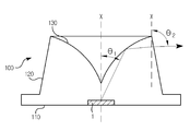
도 1은 본 발명의 일실시예에 따른 발광 확산 소자의 사시도이다.
도 2는 도 1의 발광 확산 소자의 광학 프로파일을 도시한 단면도이다.
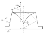
도 3 내지 도 5는 발광 확산 소자로 입사된 광 및 광축(X)이 이루는 각도를 연속적으로 증가시켰을 때 광의 프로파일을 도시한 단면도들이다.
도 6은 도 1의 발광 확산 소자의 지향각 분포를 도시한 그래프이다.
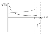
도 7은 도 1의 발광 확산 소자의 광의 방출각, 방출 방향 및 방출비를 도시한 그래프이다.
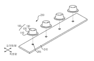
도 8은 도 1의 확산 발광 소자를 포함하는 엘이디 어레이 유닛의 분해 사시도이다.
도 9는 도 1의 확산 발광 소자를 포함하는 백라이트 어셈블리의 단면도이다.1 is a perspective view of a light emitting device according to an embodiment of the present invention.
2 is a cross-sectional view showing an optical profile of the light emitting element of FIG.
FIGS. 3 to 5 are cross-sectional views illustrating the profile of light when the angle formed by the light incident on the light-emitting element and the optical axis X is continuously increased.
FIG. 6 is a graph showing the distribution of the directivity of the light emitting device of FIG. 1;
7 is a graph showing the light emission angle, emission direction, and emission ratio of the light emitting device of FIG.
8 is an exploded perspective view of an LED array unit including the diffusion light emitting element of FIG.
FIG. 9 is a cross-sectional view of a backlight assembly including the diffusion light-emitting device of FIG. 1;
이하, 첨부된 도면들을 참조하여 본 발명에 따른 실시예를 상세히 설명한다. 이 과정에서 도면에 도시된 구성요소의 크기나 형상 등은 설명의 명료성과 편의상 과장되게 도시될 수 있다. 또한, 본 발명의 구성 및 작용을 고려하여 특별히 정의된 용어들은 사용자, 운용자의 의도 또는 관례에 따라 달라질 수 있다. 이러한 용어들에 대한 정의는 본 명세서 전반에 걸친 내용을 토대로 본 발명의 기술적 사상에 부합하는 의미와 개념으로 해석되어야 한다.Hereinafter, embodiments of the present invention will be described in detail with reference to the accompanying drawings. The sizes and shapes of the components shown in the drawings may be exaggerated for clarity and convenience. In addition, terms defined in consideration of the configuration and operation of the present invention may be changed according to the intention or custom of the user, the operator. The definitions of these terms should be interpreted based on the contents of the present specification and meanings and concepts in accordance with the technical idea of the present invention.
도 1은 본 발명의 일실시예에 따른 발광 확산 소자의 사시도이다. 도 2는 도 1의 발광 확산 소자의 광학 프로파일을 도시한 단면도이다. 도 3 내지 도 5는 발광 확산 소자로 입사된 광 및 광축(X)이 이루는 각도를 연속적으로 증가시켰을 때 광의 프로파일을 도시한 단면도들이다. 도 6은 도 1의 발광 확산 소자의 지향각 분포를 도시한 그래프이다. 도 7은 도 1의 발광 확산 소자의 광의 방출각, 방출 방향 및 방출비를 도시한 그래프이다.1 is a perspective view of a light emitting device according to an embodiment of the present invention. 2 is a cross-sectional view showing an optical profile of the light emitting element of FIG. FIGS. 3 to 5 are cross-sectional views illustrating the profile of light when the angle formed by the light incident on the light-emitting element and the optical axis X is continuously increased. FIG. 6 is a graph showing the distribution of the directivity of the light emitting device of FIG. 1; 7 is a graph showing the light emission angle, emission direction, and emission ratio of the light emitting device of FIG.
도 1 내지 도 7을 참조하면, 발광 확산 소자(100)는 제1 렌즈면(110), 제2 렌즈면(120) 및 제3 렌즈면(130)을 포함한다.1 to 7, the
제1 렌즈면(110)으로는 외부로부터 제공된 광이 입사된다. 예를 들어, 제1 렌즈면(110)으로는 발광 다이오드(1)로부터 발생된 광이 유입된다. 본 발명의 일실시예에서, 제1 렌즈면(110)은, 예를 들어, 평탄한 형상을 갖는다.Light provided from the outside is incident on the
발광 다이오드(1)로부터 발생된 광은 제1 렌즈면(110)을 통과하면서 굴절되지 않으며, 이를 구현하기 위하여 발광 다이오드(1)는 발광 확산 소자(100)의 내부에 배치되거나, 발광 확산 소자(100)의 재질을 발광다이오드(1)를 감싸는 수지와 동일한 재질로 사용할 수 있다.The light emitted from the
제2 렌즈면(120)은 제1 렌즈면(110)과 연결되며, 제2 렌즈면(120)은 제1 렌즈면(110)에 대하여 경사지게 형성된다. 제2 렌즈면(120)으로는 제1 렌즈면(110)으로 입사된 광 중 대부분의 광이 출사된다.The
본 발명의 일실시예에서, 제2 렌즈면(120)은 제1 렌즈면(110)에 대하여 수직한 광축에 대하여 0°이상 20°이하의 각도로 경사지게 형성된다. 이와 다르게, 제2 렌즈면(120)은 광축에 대하여 -45°이상 0°이하의 각도로 안쪽으로 경사지게 형성된다.In one embodiment of the present invention, the
제2 렌즈면(120)이 제1 렌즈면(110)에 대하여 경사지게 형성된 것은 제1 렌즈면(110)을 통해 입사된 광의 일부를 제2 렌즈면(120)으로부터 반사되도록 하여 발광 확산 소자(100)의 높이와 부피를 감소 및 발광 확산 소자(100)로부터 출사된 광의 휘도 균일성을 향상 시키기 위함이다.The
비록 본 발명의 일실시예에서, 제2 렌즈면(120)은 광축에 대하여 경사지게 형성된 경사면인 것이 도시 및 설명되고 있지만, 이와 다르게, 제2 렌즈면(120)은 바깥쪽으로 볼록한 곡면 또는 안쪽으로 오목하게 형성된 곡면일 수 있다.Although it is shown and described that the
제3 렌즈면(130)은 제2 렌즈면(120)에 연결되며, 제1 렌즈면(110)과 마주하게 형성된다.The
제3 렌즈면(130)은 제2 렌즈면(120)의 테두리로부터 제2 렌즈면(120)의 중앙부로 갈수록 좁고 깊게 함몰되는 형상으로 형성되며, 제3 렌즈면(130)은 단면에서 보았을 때 곡면으로 형성된다.The
제3 렌즈면(130)으로는 제1 렌즈면(110)으로부터 입사된 광 중 제2 렌즈면(120)으로부터 반사된 광이 출사된다.The
이하, 제1 내지 제3 렌즈면(110,120,130)을 갖는 발광 확산 소자(100)로 입사되는 광의 각도에 따라 발광 확산 소자(100)로부터 출사되는 광의 프로파일을 설명하기로 한다.Hereinafter, the profile of the light emitted from the
도 3 내지 도 5는 발광 확산 소자로 입사된 광 및 광축(X)이 이루는 각도를 연속적으로 증가시켰을 때 광의 프로파일을 도시한 단면도들이다.FIGS. 3 to 5 are cross-sectional views illustrating the profile of light when the angle formed by the light incident on the light-emitting element and the optical axis X is continuously increased.
도 3을 참조하면, 광축(X)에 대하여 발광 확산 소자(100)의 제1 렌즈면(110)으로 입사된 광이 이루는 각도가 θ1일 경우, 발광 확산 소자(100)의 제1 렌즈면(110)으로 입사된 광은 제3 렌즈면(130)에서 반사 및 굴절되어 제2 렌즈면(120)으로 진행하고, 제2 렌즈면(120)으로부터 출사된다.3, when the angle formed by the light incident on the
이때, 광축(X)에 대하여 제2 렌즈면(120)으로 출사되는 광의 각도는 θ2로서 정의된다.At this time, the angle of light emitted to the
이때, θ1 및 θ2의 관계는, θ2를 θ1으로 나눈 값이 1 이상 또는 θ2를 θ1으로 나눈 값이 연속적으로 증가(gradually) 되는데, 이는 제1 렌즈면(110)으로 광축(X)에 대하여 θ1의 각도로 입사된 광은 θ1보다 큰 θ2의 각도로 출사되는 것을 의미하며, 이는 발광 확산 소자(100)에 의하여 광이 확산되는 것을 의미한다.At this time, the relation between? 1 and? 2 is gradually increased by a value obtained by dividing? 2 by? 1 divided by? 1 or? 2 by? 1. This is because the
도 4를 참조하면, 광축(X)에 대하여 발광 확산 소자(100)의 제1 렌즈면(110)으로 입사된 광이 이루는 각도가 θ3(θ3>θ1)일 경우, θ3의 각도로 입사된 광은 제3 렌즈면(130)에 도달하지 못하기 때문에 θ3의 각도로 입사된 광은 제3 렌즈면(130)에서 반사 및 굴절되지 못하고 곧바로 제2 렌즈면(120)으로 진행된다. θ3의 각도로 입사된 광은 제2 렌즈면(120)으로부터 전반사되고, 제2 렌즈면(120)으로부터 전반사된 광은 제3 렌즈면(130)을 투과한다.4, when the angle formed by the light incident on the
즉, 제1 렌즈면(110)으로 입사된 광의 각도를 광축(X)에 대하여 점차 증가시킬 경우, 입사된 광은 도 3에 도시된 바와 같이 제3 렌즈면(130)에서 반사된 후 제2 렌즈면(120)을 통해 출사되지만, 제1 렌즈면(110)으로 입사된 광의 각도를 광축(X)에 대하여 점차 증가시킬 경우 입사된 광은 도 4에 도시된 바와 같이 제3 렌즈면(130)에서 반사되지 않고 곧바로 제2 렌즈면(120)에서 반사된 후 제3 렌즈면(130)을 통해 출사된다.That is, when the angle of the light incident on the
본 발명의 일실시예에서, θ3의 각도로 입사되어 제2 렌즈면(120)으로부터 전반사되어 제3 렌즈면(130)을 투과하기 위한 θ3의 각도는 예를 들어 42°내지 52°이며, θ3의 각도는 발광 확산 소자(100)의 사이즈에 따라 가변될 수 있다.In an embodiment of the present invention, the angle of? 3 for entering the angle of? 3 and totally reflected from the
도 5을 참조하면, 광축(X)에 대하여 발광 확산 소자(100)의 제1 렌즈면(110)으로 입사된 광이 이루는 각도가 θ5(θ5>θ3)일 경우, 발광 확산 소자(100)의 제1 렌즈면(110)으로 입사된 광은 제3 렌즈면(130)에서 반사 및 굴절되지 않고 제2 렌즈면(120)으로 진행하고, 제2 렌즈면(120)으로부터 곧바로 출사된다.5, when the angle formed by the light incident on the
이때, 광축(X)에 대하여 제2 렌즈면(120)으로 출사되는 광의 각도는 θ6로서 정의된다.At this time, the angle of light emitted to the
이때, θ5 및 θ6의 관계는, θ6을 θ5으로 나눈 값이 1 이상 또는 θ6을 θ5로 나눈 값이 연속적으로 증가(gradually) 되는데, 이는 제1 렌즈면(110)으로 광축(X)에 대하여 θ5의 각도로 입사된 광은 θ5보다 큰 θ6의 각도로 출사되는 것을 의미하며, 이는 발광 확산 소자(100)에 의하여 광이 확산되는 것을 의미한다.At this time, the relationship between? 5 and? 6 is gradually increased by a value obtained by dividing? 6 by? 5 or by ?5 by? 5, which is gradually increased toward the
도 6을 참조하면, 발광 확산 소자(100)로 입사되어 발광 확산 소자(100)로부터 출사된 광의 지향각은 수평에 대하여 약 160°의 각도로 퍼지며, 우수한 광 확산 특성을 갖게 되는데 이는 제1 렌즈면(110)으로 입사된 광의 일부는 제2 렌즈면(120)으로 출사되고, 제1 렌즈면(110)으로 입사된 광의 나머지는 제3 렌즈면(130)으로 출사되기 때문이다.Referring to FIG. 6, the directivity angle of the light incident on the
도 7의 그래프에서 그래프 A는 발광 확산 소자(100)로 입사된 광의 입사각을 발광 확산 소자(100)로부터 출사된 출사각으로 나눈 값의 변화를 나타내며, 그래프 B는 발광 확산 소자(100)로 입사된 광의 출사각을 나타낸다. 도 7의 그래프에서 X축은 입사각이며, Y 축은 출사각 및 방향을 나타내며, 도 7의 그래프에서 발광 확산 소자(100)로 입사된 광의 입사각이 증가됨에 따라 특정 입사각에서 광의 출사 방향이 불연속적으로 반대 방향이 되는 구간(a, b)이 나타나는데, 이는 구간(a,b)에서는 발광 확산 소자(100)의 제2 렌즈면(120)에서 광이 반사되어 제3 렌즈면(130)으로 출사되기 때문이다.7, the graph A shows a change in the value obtained by dividing the incident angle of the light incident on the
본 발명의 일실시예에서는 발광 확산 소자로 입사된 광을 제3 렌즈부(130)에서 반사시켜 제2 렌즈부(120)로 출사, 발광 확산 소자(100)로 입사된 광을 반사 또는 굴절 없이 제2 렌즈부(120)를 통해 출사 또는 발광 확산 소자(100)로 입사된 광을 제2 렌즈부(120)에서 반사시켜 제3 렌즈부(130)를 통해 출사 시킴으로써 광학 렌즈의 휘도 균일성을 크게 향상시킬 수 있다.In an embodiment of the present invention, the light incident on the light emitting diffuser is reflected by the
도 8는 도 1의 확산 발광 소자를 포함하는 엘이디 어레이 유닛의 분해 사시도이다. 도 8에 도시된 엘이디 어레이 유닛은 도 1 내지 도 7에 도시된 엘이디 어레이 유닛과 실질적으로 동일한 구성을 갖는다. 따라서, 동일한 구성에 대한 중복된 설명은 생략하기로 하며, 동일한 구성에 대해서는 동일한 명칭 및 동일한 참조 부호를 부여하기로 한다.8 is an exploded perspective view of an LED array unit including the diffusion light emitting element of FIG. The LED array unit shown in Fig. 8 has substantially the same configuration as the LED array unit shown in Figs. 1 to 7. Therefore, redundant description of the same configuration will be omitted, and the same names and the same reference numerals will be given to the same configurations.
도 8을 참조하면, 엘이디 어레이 유닛(250)은 확산 발광 소자(100), 회로 기판(205) 및 발광 다이오드(210)를 포함한다.Referring to FIG. 8, the
회로 기판(205)은 단변 보다 장변이 긴 직사각형 플레이트 형상으로 형성되며, 확산 발광 소자(205)에는 회로 패턴(미도시)이 형성된다.The
회로 패턴(205)은 후술 될 발광 다이오드(210)로 구동 신호를 제공하는 역할을 한다.The
발광 다이오드(210)는 회로 기판(205)의 회로 패턴에 전기적으로 연결되고 회로 패턴에 인가된 구동 신호에 의하여 광을 발생시킨다.The
발광 다이오드(210)로부터 발생된 광은 360도 방향으로 특정 지향각으로 퍼지는 광 프로파일을 가지며, 발광 다이오드(210)로부터 발생된 광은 고휘도 특성을 갖는 반면 휘도 균일성은 크게 떨어지는 광 프로파일을 갖는다.The light emitted from the
이와 같이 고휘도 특성을 갖는 반면 휘도 균일성이 크게 감소 되는 광 프로파일을 갖는 발광 다이오드(210)의 휘도 균일성을 개선하기 위하여 각 발광 다이오드(210)에는 확산 발광 소자(100)가 배치된다.The diffused
발광 확산 소자(100)는 제1 렌즈면(110), 제2 렌즈면(120) 및 제3 렌즈면(130)을 포함한다.The
발광 확산 소자(100)는 발광 다이오드(210)로부터 발생 된 광을 보다 효율적으로 확산시키기 위해서 발광 다이오드(210)로부터 발생된 광의 일부는 제2 렌즈면(120)으로 직접 출사되고, 발생된 광의 일부는 제3 렌즈(130)에 반사되어 제2 렌즈면(120)으로 출사되고, 발생된 광의 일부는 제2 렌즈면(120)으로부터 반사된 후 제3 렌즈(130)면으로부터 출사된다.In order to more efficiently diffuse the light emitted from the
확산 발광 소자(100)의 제1 렌즈면(110)에는 발광 다이오드(210)를 수납하기에 적합한 홈이 형성된다. 이와 다르게, 발광 다이오드(210)는 제1 렌즈면(110)에 일체로 사출 성형될 수 있다.A groove suitable for receiving the
이와 같이 확산 발광 소자(100)를 이용하여 광의 휘도 균일성을 크게 향상시킬 경우 보다 적은 개수의 발광 다이오드(210)를 이용하여 고휘도 및 높은 휘도 균일성을 갖는 광 프로파일을 형성할 수 있을 뿐만 아니라 소비전력을 보다 감소시킬 수 있다.In the case where the brightness uniformity of the light is greatly improved by using the diffusion
도 9는 도 1의 확산 발광 소자를 포함하는 백라이트 어셈블리의 단면도이다. 도 9에 도시된 백라이트 어셈블리 중 엘이디 어레이 유닛은 도 8에 도시된 엘이디 어레이 유닛과 실질적으로 동일한 구성을 갖는다. 따라서, 동일한 구성에 대한 중복된 설명은 생략하기로 하며, 동일한 구성에 대해서는 동일한 명칭 및 동일한 참조 부호를 부여하기로 한다.FIG. 9 is a cross-sectional view of a backlight assembly including the diffusion light-emitting device of FIG. 1; The LED array unit of the backlight assembly shown in Fig. 9 has substantially the same configuration as that of the LED array unit shown in Fig. Therefore, redundant description of the same configuration will be omitted, and the same names and the same reference numerals will be given to the same configurations.
도 9를 참조하면, 백라이트 어셈블리(300)는 엘이디 어레이 유닛(250), 바텀 케이스(310) 및 반사판(320)을 포함한다. 이에 더하여, 백라이트 어셈블리(300)는 확산 부재(330)를 더 포함할 수 있다.Referring to FIG. 9, the backlight assembly 300 includes an
바텀 케이스(310)는 바닥판(305) 및 측면판(307)을 포함한다.The bottom case 310 includes a bottom plate 305 and a side plate 307.
바닥판(305)은, 예를 들어, 사각 플레이트 형상으로 형성되며, 측면판(307)은 바닥판(305)으로부터 상부로 연장된 형상으로 바닥판(305) 및 측면판(307)에 의하여 바텀 케이스(310)의 내부에는 수납 공간이 형성된다.The bottom plate 305 is formed in the shape of a square plate and the side plate 307 is formed in a shape extending upward from the bottom plate 305 by the bottom plate 305 and the side plate 307, A storage space is formed inside the case 310.
반사판(320)은 바텀 케이스(310)의 바닥판(305) 상에 배치되며, 바닥판(305)에 배치된 반사판(320)은 엘이디 어레이 유닛(250)의 확산 발광 소자(100)로부터 출사된 광을 반사시키는 역할을 한다.The reflection plate 320 is disposed on the bottom plate 305 of the bottom case 310 and the reflection plate 320 disposed on the bottom plate 305 is disposed on the bottom of the bottom plate 305 of the
본 발명의 일실시예에서, 엘이디 어레이 유닛(250)은 반사판(320) 상에 배치될 수 있고, 반사판(320) 중 엘이디 어레이 유닛(250)의 사이에 대응하는 부분은 '∧'자 형상으로 절곡되어 엘이디 어레이 유닛(250)의 확산 발광 소자(100)로부터 출사된 광을 바텀 케이스(310)의 바닥판(305)에 대하여 수직한 방향으로 반사할 수 있다.In one embodiment of the present invention, the
바텀 케이스(310)의 측면판(307)의 상단에는 확산 부재(330)가 배치되는데, 확산 부재(330)는 엘이디 어레이 유닛(250)의 확산 발광 소자(100)의 광 출사면(20)으로부터 출사된 광을 다시 한번 확산시켜 발광 다이오드(210)로부터 발생된 광의 휘도 균일성을 보다 향상시킬 수 있다.A diffusing member 330 is disposed at an upper end of the side plate 307 of the bottom case 310. The diffusing member 330 extends from the light exit surface 20 of the diffusing light emitting
이상에서 상세하게 설명한 바에 의하면, 발광 확산 소자로 입사된 광의 투과 및 반사 조건을 변경하여 광의 확산 경로를 다변화시킴으로써 점 광원인 발광 다이오드로부터 발생 된 광의 휘도 분포를 크게 향상시키고 발광 확산 소자의 사이즈를 보다 감소시킬 수 있는 효과를 갖는다.As described above in detail, by varying the transmission and reflection conditions of light incident on the light-emitting diffusing element to diversify the diffusion path of the light, the luminance distribution of the light emitted from the light-emitting diode as the point light source is greatly improved and the size of the light- It has an effect that can be reduced.
이상에서 본 발명에 따른 실시예들이 설명되었으나, 이는 예시적인 것에 불과하며, 당해 분야에서 통상적 지식을 가진 자라면 이로부터 다양한 변형 및 균등한 범위의 실시예가 가능하다는 점을 이해할 것이다. 따라서, 본 발명의 진정한 기술적 보호 범위는 다음의 특허청구범위에 의해서 정해져야 할 것이다.
While the invention has been shown and described with reference to certain preferred embodiments thereof, it will be understood by those skilled in the art that various changes and modifications may be made without departing from the spirit and scope of the invention as defined by the appended claims. Accordingly, the true scope of the present invention should be determined by the following claims.
100...발광 확산 소자 110...렌즈면
120...제2 렌즈면 130...제3 렌즈면
250...엘이디 어레이 유닛 300...백라이트 어셈블리100 ... light
120 ...
250 ... LED array unit 300 ... backlight assembly
Claims (19)
상기 제1 렌즈면과 연결되며, 상기 제1 렌즈면에 대하여 수직한 광축에 대하여 제1 각도로 입사된 광을 출사 시키는 제2 렌즈면; 및
상기 제2 렌즈면에 연결되어 중앙부로 갈수록 좁고 깊게 함몰되며, 상기 제1 렌즈면을 통해 상기 광축에 대하여 제2 각도로 입사된 광을 반사시켜 상기 제2 렌즈면으로 출사시키는 제3 렌즈면을 포함하며,
상기 제1 렌즈면을 통해 상기 광축에 대하여 제3 각도로 입사된 광은 상기 제2 렌즈면에서 반사되어 상기 제3 렌즈면으로 출사되는 발광 확산 소자.
A first lens surface;
A second lens surface that is connected to the first lens surface and emits light incident at a first angle with respect to an optical axis perpendicular to the first lens surface; And
And a third lens surface that is connected to the second lens surface and is narrowed and deeply recessed toward the center and reflects light incident at a second angle with respect to the optical axis through the first lens surface and outputs the light to the second lens surface ≪ / RTI &
Wherein light incident at a third angle with respect to the optical axis through the first lens surface is reflected by the second lens surface and is emitted to the third lens surface.
상기 제1 렌즈면으로 상기 광을 제공하는 발광 다이오드를 더 포함하는 발광 확산 소자.
The method according to claim 1,
And a light emitting diode for providing the light to the first lens surface.
상기 발광 다이오드는 상기 제1 렌즈면의 내부에 일체로 실장된 발광 확산 소자.
3. The method of claim 2,
Wherein the light emitting diode is integrally mounted inside the first lens surface.
상기 발광 다이오드는 상기 제1 렌즈면과 이격된 위치에 배치된 발광 확산 소자.
3. The method of claim 2,
Wherein the light emitting diode is disposed at a position spaced apart from the first lens surface.
상기 제1 렌즈면으로 입사되는 상기 광들은 상기 제1 렌즈면에서 굴절하여 상기 제2 렌즈면 또는 제3 렌즈면으로 입사되는 발광 확산 소자.
The method according to claim 1,
Wherein the light incident on the first lens surface is refracted by the first lens surface and is incident on the second lens surface or the third lens surface.
상기 제1 각도는 상기 제2 각도 및 상기 제3 각도보다 크고, 상기 제3 각도는 상기 제2 각도보다 크게 형성된 발광 확산 소자.
The method according to claim 1,
Wherein the first angle is larger than the second angle and the third angle, and the third angle is larger than the second angle.
상기 제2 렌즈면은 상기 광축에 대하여 경사지게 형성된 발광 확산 소자.
The method according to claim 1,
And the second lens surface is inclined with respect to the optical axis.
상기 제2 렌즈면은 상기 광축에 대하여 0°이상 40°이하의 각도로 바깥쪽으로 경사지게 형성된 발광 확산 소자.
8. The method of claim 7,
And the second lens surface is inclined outward at an angle of not less than 40 degrees with respect to the optical axis.
상기 제2 렌즈면은 바깥쪽으로 볼록한 곡면으로 형성된 발광 확산 소자.
8. The method of claim 7,
And the second lens surface has a convex curved surface outwardly.
상기 제1 렌즈면으로 입사되는 상기 광은 상기 광축을 기준으로 -80°~ 80°인 발광 확산 소자.
The method according to claim 1,
Wherein the light incident on the first lens surface is -80 DEG to 80 DEG with respect to the optical axis.
상기 제3 각도는 상기 광축을 기준으로 45°내지 80°인 발광 확산 소자.
The method according to claim 1,
And the third angle is 45 DEG to 80 DEG with respect to the optical axis.
상기 제2 렌즈면은 상기 광축에 대하여 -45° 이상 0°이하의 각도로 안쪽으로 경사지게 형성된 발광 확산 소자.
8. The method of claim 7,
And the second lens surface is inclined inward at an angle of not less than -45 DEG and not more than 0 DEG with respect to the optical axis.
상기 제2 렌즈면은 안쪽으로 오목한 곡면으로 형성된 발광 확산 소자.
8. The method of claim 7,
And the second lens surface is formed as a concave curved surface inward.
상기 제1 렌즈면으로 광을 제공하는 발광 다이오드; 및
상기 발광 다이오드 및 상기 발광 확산 소자가 결합되는 회로 기판을 포함하는 엘이디 어레이 유닛.
A first lens surface, a second lens surface connected to the first lens surface, for emitting light incident at a first angle with respect to an optical axis perpendicular to the first lens surface, and a second lens surface connected to the second lens surface, And a third lens surface that is gradually and narrowly recessed and reflects light incident at a second angle with respect to the optical axis through the first lens surface to exit to the second lens surface, A light diffusing element that is incident on the optical axis at a third angle and is reflected by the second lens surface and emitted to the third lens surface;
A light emitting diode for providing light to the first lens surface; And
And a circuit board to which the light emitting diode and the light emitting diodes are coupled.
상기 회로 기판은 직사각형 플레이트 형상으로 형성되고, 상기 발광다이오드들은 상기 회로 기판의 장변 방향을 따라 형성된 엘이디 어레이 유닛.
15. The method of claim 14,
Wherein the circuit board is formed in the shape of a rectangular plate, and the light emitting diodes are formed along the long side direction of the circuit board.
상기 제1 각도는 상기 제2 각도 및 상기 제3 각도보다 크고, 상기 제3 각도는 상기 제2 각도보다 크게 형성된 엘이디 어레이 유닛.
15. The method of claim 14,
Wherein the first angle is larger than the second angle and the third angle, and the third angle is larger than the second angle.
내부에 수납공간이 형성되며 상기 엘이디 어레이 유닛을 수납하는 바텀 케이스;
상기 바텀 케이스의 바닥판 상에 배치된 광 반사판; 및
상기 광 반사판과 이격되며 상기 바텀 케이스에 결합된 광 확산판을 포함하는 백라이트 어셈블리.
A first lens surface, a second lens surface connected to the first lens surface, for emitting light incident at a first angle with respect to an optical axis perpendicular to the first lens surface, and a second lens surface connected to the second lens surface, And a third lens surface that is gradually and narrowly recessed and reflects light incident at a second angle with respect to the optical axis through the first lens surface to exit to the second lens surface, A light emitting diode for emitting light to the first lens surface and a light emitting diode for emitting light to the first lens surface; An LED array unit including a circuit board to which the light emitting diodes are coupled;
A bottom case in which a storage space is formed and accommodates the LED array unit;
A light reflector disposed on a bottom plate of the bottom case; And
And a light diffusing plate spaced apart from the light reflecting plate and coupled to the bottom case.
상기 바텀 케이스 상에는 상기 엘이디 어레이 유닛으로부터 출사된 광을 확산시키는 확산 부재가 배치된 백라이트 어셈블리.
18. The method of claim 17,
And a diffusion member for diffusing light emitted from the LED array unit is disposed on the bottom case.
상기 제1 각도는 상기 제2 각도 및 상기 제3 각도보다 크고, 상기 제3 각도는 상기 제2 각도보다 크게 형성된 백라이트 어셈블리.18. The method of claim 17,
Wherein the first angle is greater than the second angle and the third angle, and the third angle is greater than the second angle.
Priority Applications (1)
| Application Number | Priority Date | Filing Date | Title |
|---|---|---|---|
| KR1020120145900A KR102093649B1 (en) | 2012-12-14 | 2012-12-14 | Dfusion-light emitting element, led array unit having the same, and back light assembly having the same |
Applications Claiming Priority (1)
| Application Number | Priority Date | Filing Date | Title |
|---|---|---|---|
| KR1020120145900A KR102093649B1 (en) | 2012-12-14 | 2012-12-14 | Dfusion-light emitting element, led array unit having the same, and back light assembly having the same |
Publications (2)
| Publication Number | Publication Date |
|---|---|
| KR20140077292A true KR20140077292A (en) | 2014-06-24 |
| KR102093649B1 KR102093649B1 (en) | 2020-03-26 |
Family
ID=51129244
Family Applications (1)
| Application Number | Title | Priority Date | Filing Date |
|---|---|---|---|
| KR1020120145900A Expired - Fee Related KR102093649B1 (en) | 2012-12-14 | 2012-12-14 | Dfusion-light emitting element, led array unit having the same, and back light assembly having the same |
Country Status (1)
| Country | Link |
|---|---|
| KR (1) | KR102093649B1 (en) |
Cited By (3)
| Publication number | Priority date | Publication date | Assignee | Title |
|---|---|---|---|---|
| CN105841019A (en) * | 2014-12-16 | 2016-08-10 | 文晔科技股份有限公司 | Light emitting device |
| WO2017131396A1 (en) * | 2016-01-25 | 2017-08-03 | 삼성전자주식회사 | Lens and display device having same |
| KR102152649B1 (en) * | 2020-06-19 | 2020-09-07 | 주식회사 에이치엘옵틱스 | Lens for support a diffusion plate |
Citations (3)
| Publication number | Priority date | Publication date | Assignee | Title |
|---|---|---|---|---|
| KR100726160B1 (en) * | 2006-06-30 | 2007-06-13 | 서울반도체 주식회사 | Lens and light emitting device using same |
| WO2008007492A1 (en) * | 2006-07-11 | 2008-01-17 | Koha Co., Ltd. | Light source module, surface area light-emitting unit, and surface area light-emitting device |
| JP2011100134A (en) * | 2009-11-04 | 2011-05-19 | Nalux Co Ltd | Lighting device |
-
2012
- 2012-12-14 KR KR1020120145900A patent/KR102093649B1/en not_active Expired - Fee Related
Patent Citations (3)
| Publication number | Priority date | Publication date | Assignee | Title |
|---|---|---|---|---|
| KR100726160B1 (en) * | 2006-06-30 | 2007-06-13 | 서울반도체 주식회사 | Lens and light emitting device using same |
| WO2008007492A1 (en) * | 2006-07-11 | 2008-01-17 | Koha Co., Ltd. | Light source module, surface area light-emitting unit, and surface area light-emitting device |
| JP2011100134A (en) * | 2009-11-04 | 2011-05-19 | Nalux Co Ltd | Lighting device |
Cited By (4)
| Publication number | Priority date | Publication date | Assignee | Title |
|---|---|---|---|---|
| CN105841019A (en) * | 2014-12-16 | 2016-08-10 | 文晔科技股份有限公司 | Light emitting device |
| WO2017131396A1 (en) * | 2016-01-25 | 2017-08-03 | 삼성전자주식회사 | Lens and display device having same |
| US10643527B2 (en) | 2016-01-25 | 2020-05-05 | Samsung Electronics Co., Ltd. | Lens and display apparatus having the same |
| KR102152649B1 (en) * | 2020-06-19 | 2020-09-07 | 주식회사 에이치엘옵틱스 | Lens for support a diffusion plate |
Also Published As
| Publication number | Publication date |
|---|---|
| KR102093649B1 (en) | 2020-03-26 |
Similar Documents
| Publication | Publication Date | Title |
|---|---|---|
| US7422357B1 (en) | Optical plate and backlight module using the same | |
| CN104075241B (en) | Optical lens, light-emitting device, and lighting device | |
| US7722241B2 (en) | Optical plate and backlight module using the same | |
| US7810983B2 (en) | Optical plate and backlight module using the same | |
| KR101329413B1 (en) | Optical lens, optical module having the optical lens and backlight unit having the optical module | |
| US20060285311A1 (en) | Light-emitting device, backlight module, and liquid crystal display using the same | |
| US7740374B2 (en) | Optical plate and backlight module using the same | |
| US7670020B2 (en) | Optical plate and backlight module using the same | |
| CN102472447A (en) | Lens unit, light-emitting module, lighting device, display device, and television receiver | |
| US20080266872A1 (en) | Optical plate and backlight module using the same | |
| US20140177235A1 (en) | Optical lens and lighting device having the same | |
| KR20150026253A (en) | Lens module, light source assembly and backlight assembly having the lens module | |
| KR101426600B1 (en) | A light scattering lens for planar light source device of liquid crystal displays | |
| US7556417B2 (en) | Optical plate and backlight module using the same | |
| JP2011517040A (en) | LIGHTING SYSTEM, BACKLIGHT SYSTEM, AND DISPLAY DEVICE | |
| US7837373B2 (en) | Optical plate having encircling protrusions and elongated V-shaped protrusions and backlight module using the same | |
| KR101419031B1 (en) | Light emitting device and lighting device having the same | |
| KR20140088679A (en) | Backlight assembly and display device using the same | |
| KR20140064189A (en) | Led lens for wide diffusion light | |
| US7918599B2 (en) | Optical plate and backlight module using the same | |
| JP2007048489A (en) | Backlight device | |
| KR20140077292A (en) | Dfusion-light emitting element, led array unit having the same, and back light assembly having the same | |
| US20060249742A1 (en) | Light emitting device for achieving uniform light distribution and backlight unit employing the same | |
| US20080266877A1 (en) | Optical plate and backlight module using the same | |
| US20090147533A1 (en) | Display Device |
Legal Events
| Date | Code | Title | Description |
|---|---|---|---|
| PA0109 | Patent application |
St.27 status event code: A-0-1-A10-A12-nap-PA0109 |
|
| P11-X000 | Amendment of application requested |
St.27 status event code: A-2-2-P10-P11-nap-X000 |
|
| P13-X000 | Application amended |
St.27 status event code: A-2-2-P10-P13-nap-X000 |
|
| PG1501 | Laying open of application |
St.27 status event code: A-1-1-Q10-Q12-nap-PG1501 |
|
| PN2301 | Change of applicant |
St.27 status event code: A-3-3-R10-R13-asn-PN2301 St.27 status event code: A-3-3-R10-R11-asn-PN2301 |
|
| R18-X000 | Changes to party contact information recorded |
St.27 status event code: A-3-3-R10-R18-oth-X000 |
|
| A201 | Request for examination | ||
| PA0201 | Request for examination |
St.27 status event code: A-1-2-D10-D11-exm-PA0201 |
|
| R18-X000 | Changes to party contact information recorded |
St.27 status event code: A-3-3-R10-R18-oth-X000 |
|
| D13-X000 | Search requested |
St.27 status event code: A-1-2-D10-D13-srh-X000 |
|
| D14-X000 | Search report completed |
St.27 status event code: A-1-2-D10-D14-srh-X000 |
|
| E902 | Notification of reason for refusal | ||
| PE0902 | Notice of grounds for rejection |
St.27 status event code: A-1-2-D10-D21-exm-PE0902 |
|
| E13-X000 | Pre-grant limitation requested |
St.27 status event code: A-2-3-E10-E13-lim-X000 |
|
| P11-X000 | Amendment of application requested |
St.27 status event code: A-2-2-P10-P11-nap-X000 |
|
| P13-X000 | Application amended |
St.27 status event code: A-2-2-P10-P13-nap-X000 |
|
| P22-X000 | Classification modified |
St.27 status event code: A-2-2-P10-P22-nap-X000 |
|
| E902 | Notification of reason for refusal | ||
| PE0902 | Notice of grounds for rejection |
St.27 status event code: A-1-2-D10-D21-exm-PE0902 |
|
| E13-X000 | Pre-grant limitation requested |
St.27 status event code: A-2-3-E10-E13-lim-X000 |
|
| P11-X000 | Amendment of application requested |
St.27 status event code: A-2-2-P10-P11-nap-X000 |
|
| P13-X000 | Application amended |
St.27 status event code: A-2-2-P10-P13-nap-X000 |
|
| E701 | Decision to grant or registration of patent right | ||
| PE0701 | Decision of registration |
St.27 status event code: A-1-2-D10-D22-exm-PE0701 |
|
| R18-X000 | Changes to party contact information recorded |
St.27 status event code: A-3-3-R10-R18-oth-X000 |
|
| PR0701 | Registration of establishment |
St.27 status event code: A-2-4-F10-F11-exm-PR0701 |
|
| PR1002 | Payment of registration fee |
St.27 status event code: A-2-2-U10-U11-oth-PR1002 Fee payment year number: 1 |
|
| PG1601 | Publication of registration |
St.27 status event code: A-4-4-Q10-Q13-nap-PG1601 |
|
| PN2301 | Change of applicant |
St.27 status event code: A-5-5-R10-R13-asn-PN2301 St.27 status event code: A-5-5-R10-R11-asn-PN2301 |
|
| PN2301 | Change of applicant |
St.27 status event code: A-5-5-R10-R11-asn-PN2301 |
|
| PN2301 | Change of applicant |
St.27 status event code: A-5-5-R10-R14-asn-PN2301 |
|
| PR1001 | Payment of annual fee |
St.27 status event code: A-4-4-U10-U11-oth-PR1001 Fee payment year number: 4 |
|
| PC1903 | Unpaid annual fee |
St.27 status event code: A-4-4-U10-U13-oth-PC1903 Not in force date: 20240321 Payment event data comment text: Termination Category : DEFAULT_OF_REGISTRATION_FEE |
|
| PC1903 | Unpaid annual fee |
St.27 status event code: N-4-6-H10-H13-oth-PC1903 Ip right cessation event data comment text: Termination Category : DEFAULT_OF_REGISTRATION_FEE Not in force date: 20240321 |