KR20140077384A - Produced water de-sander system - Google Patents
Produced water de-sander system Download PDFInfo
- Publication number
- KR20140077384A KR20140077384A KR1020120146144A KR20120146144A KR20140077384A KR 20140077384 A KR20140077384 A KR 20140077384A KR 1020120146144 A KR1020120146144 A KR 1020120146144A KR 20120146144 A KR20120146144 A KR 20120146144A KR 20140077384 A KR20140077384 A KR 20140077384A
- Authority
- KR
- South Korea
- Prior art keywords
- accumulator
- sand
- produced water
- centrifugal separator
- channel
- Prior art date
- Legal status (The legal status is an assumption and is not a legal conclusion. Google has not performed a legal analysis and makes no representation as to the accuracy of the status listed.)
- Withdrawn
Links
- XLYOFNOQVPJJNP-UHFFFAOYSA-N water Substances O XLYOFNOQVPJJNP-UHFFFAOYSA-N 0.000 title claims abstract description 53
- 239000004576 sand Substances 0.000 claims abstract description 58
- 239000010779 crude oil Substances 0.000 claims abstract description 29
- 239000003921 oil Substances 0.000 claims abstract description 23
- 238000000034 method Methods 0.000 claims abstract description 15
- 230000005484 gravity Effects 0.000 claims abstract description 5
- 239000007788 liquid Substances 0.000 claims description 10
- 239000002002 slurry Substances 0.000 abstract description 17
- 238000009434 installation Methods 0.000 abstract description 3
- 238000000746 purification Methods 0.000 abstract description 3
- 239000007789 gas Substances 0.000 description 12
- 238000005553 drilling Methods 0.000 description 9
- 239000012530 fluid Substances 0.000 description 7
- 238000007670 refining Methods 0.000 description 7
- 238000000926 separation method Methods 0.000 description 5
- 238000011161 development Methods 0.000 description 3
- 238000007667 floating Methods 0.000 description 3
- 229930195733 hydrocarbon Natural products 0.000 description 3
- 150000002430 hydrocarbons Chemical class 0.000 description 3
- 238000012423 maintenance Methods 0.000 description 3
- 238000012545 processing Methods 0.000 description 3
- 238000007599 discharging Methods 0.000 description 2
- 230000000694 effects Effects 0.000 description 2
- 238000004519 manufacturing process Methods 0.000 description 2
- 230000003247 decreasing effect Effects 0.000 description 1
- 238000005516 engineering process Methods 0.000 description 1
- 238000003912 environmental pollution Methods 0.000 description 1
- 238000004880 explosion Methods 0.000 description 1
- 238000005065 mining Methods 0.000 description 1
- 238000012986 modification Methods 0.000 description 1
- 230000004048 modification Effects 0.000 description 1
- 239000003129 oil well Substances 0.000 description 1
- 239000002245 particle Substances 0.000 description 1
- 230000002093 peripheral effect Effects 0.000 description 1
- 239000003208 petroleum Substances 0.000 description 1
- 231100000614 poison Toxicity 0.000 description 1
- 239000013535 sea water Substances 0.000 description 1
- 239000007787 solid Substances 0.000 description 1
- 239000000126 substance Substances 0.000 description 1
- 239000002341 toxic gas Substances 0.000 description 1
- 239000003440 toxic substance Substances 0.000 description 1
- 231100000419 toxicity Toxicity 0.000 description 1
- 230000001988 toxicity Effects 0.000 description 1
- 230000032258 transport Effects 0.000 description 1
- 239000003643 water by type Substances 0.000 description 1
Images

Classifications
-
- E—FIXED CONSTRUCTIONS
- E21—EARTH OR ROCK DRILLING; MINING
- E21B—EARTH OR ROCK DRILLING; OBTAINING OIL, GAS, WATER, SOLUBLE OR MELTABLE MATERIALS OR A SLURRY OF MINERALS FROM WELLS
- E21B43/00—Methods or apparatus for obtaining oil, gas, water, soluble or meltable materials or a slurry of minerals from wells
- E21B43/34—Arrangements for separating materials produced by the well
- E21B43/35—Arrangements for separating materials produced by the well specially adapted for separating solids
-
- B—PERFORMING OPERATIONS; TRANSPORTING
- B04—CENTRIFUGAL APPARATUS OR MACHINES FOR CARRYING-OUT PHYSICAL OR CHEMICAL PROCESSES
- B04B—CENTRIFUGES
- B04B15/00—Other accessories for centrifuges
-
- B—PERFORMING OPERATIONS; TRANSPORTING
- B04—CENTRIFUGAL APPARATUS OR MACHINES FOR CARRYING-OUT PHYSICAL OR CHEMICAL PROCESSES
- B04B—CENTRIFUGES
- B04B5/00—Other centrifuges
- B04B5/10—Centrifuges combined with other apparatus, e.g. electrostatic separators; Sets or systems of several centrifuges
-
- E—FIXED CONSTRUCTIONS
- E21—EARTH OR ROCK DRILLING; MINING
- E21B—EARTH OR ROCK DRILLING; OBTAINING OIL, GAS, WATER, SOLUBLE OR MELTABLE MATERIALS OR A SLURRY OF MINERALS FROM WELLS
- E21B21/00—Methods or apparatus for flushing boreholes, e.g. by use of exhaust air from motor
- E21B21/06—Arrangements for treating drilling fluids outside the borehole
- E21B21/063—Arrangements for treating drilling fluids outside the borehole by separating components
- E21B21/065—Separating solids from drilling fluids
-
- E—FIXED CONSTRUCTIONS
- E21—EARTH OR ROCK DRILLING; MINING
- E21B—EARTH OR ROCK DRILLING; OBTAINING OIL, GAS, WATER, SOLUBLE OR MELTABLE MATERIALS OR A SLURRY OF MINERALS FROM WELLS
- E21B27/00—Containers for collecting or depositing substances in boreholes or wells, e.g. bailers, baskets or buckets for collecting mud or sand; Drill bits with means for collecting substances, e.g. valve drill bits
- E21B27/02—Dump bailers, i.e. containers for depositing substances, e.g. cement or acids
Landscapes
- Engineering & Computer Science (AREA)
- Life Sciences & Earth Sciences (AREA)
- Geology (AREA)
- Mining & Mineral Resources (AREA)
- Physics & Mathematics (AREA)
- Environmental & Geological Engineering (AREA)
- Fluid Mechanics (AREA)
- General Life Sciences & Earth Sciences (AREA)
- Geochemistry & Mineralogy (AREA)
- Mechanical Engineering (AREA)
- Earth Drilling (AREA)
Abstract
본 발명은 프로듀스드 워터 디-샌더 시스템에 관한 것으로서, 더욱 상세하게는 시추된 원유에 대한 정제 작업 전에 원유에 섞인 모래 및 슬러리 등을 분리함으로써 원유 정제를 위한 장비의 고장을 방지하고, 하나의 어큐뮬레이터를 구성하는 버티컬 타입으로 제공되어 설치 공간의 효율성을 높인 프로듀스드 워터 디-샌더 시스템에 관한 것이다.
이를 위해, 해저로부터 시추된 원유(crude oil)를 비중을 이용해 가스, 오일, 프로듀스드 워터를 분리하여 저장한 오일 리저버(oil reservoir)에 있어서,오일 리저버로부터 프로듀스드 워터가 공급되는 공급유로;상기 공급유로에 연결되며, 프로듀스드 워터를 원심분리하는 복수의 원심분리기;상기 원심분리기의 하방에 설치되며, 원심분리기로부터 분리된 모래를 저장하는 하나의 어큐뮬레이터;상기 어큐뮬레이터의 하방에 설치되며, 어큐뮬레이터의 모래를 수집하는 트레이;상기 각각의 원심분리기에 설치되며, 어큐뮬레이터로 모래가 낙하되는 관로를 형성하는 복수의 제1수직유로;상기 복수의 제1수직유로와 어큐뮬레이터 사이에 설치된 하나의 취합유로;상기 각각의 제1수직유로에 설치된 자동밸브;상기 어큐뮬레이터와 트레이 사이에 설치되며, 자중에 의해 모래가 낙하되는 관로를 형성하는 제2수직유로:를 포함하여 구성된 프로듀스드 워터 디-샌더 시스템을 제공한다.The present invention relates to a produced water de-sander system, and more particularly, to a method and apparatus for separating sand and slurry mixed with crude oil before purification of drilled crude oil to prevent the equipment for crude oil purification from failing, Sander system, which is provided as a vertical type constituting the water-sander system, thereby improving the installation space efficiency.
To this end, an oil reservoir in which gas, oil, and produced water are separated and stored using a specific gravity of crude oil drilled from the seabed, comprising: a supply passage through which the produced water is supplied from the oil reservoir; A plurality of centrifugal separators connected to the supply flow channel for centrifugally separating the produced water, an accumulator disposed below the centrifugal separator for storing sand separated from the centrifugal separator, an accumulator disposed below the accumulator, A plurality of first vertical channels formed in each of the centrifuges and forming a channel through which the sand is dropped by an accumulator, a collecting channel provided between the plurality of first vertical channels and the accumulator, An automatic valve provided in each of the first vertical flow passages, and a second valve disposed between the accumulator and the tray, And a second vertical flow passage for forming a channel through which sand is dropped.
Description
본 발명은 프로듀스드 워터 시스템에 관한 것으로서, 더욱 상세하게는 시추된 원유에 포함된 모래 및 슬러리를 분리하여 처리할 수 있도록 한 프로듀스드 워터 디-샌더 시스템에 관한 것이다.The present invention relates to a produced water system, and more particularly, to a produced water de-sander system capable of separately processing sand and slurry contained in drilling crude oil.
국제적인 급격한 산업화 현상과 공업이 발전함에 따라 석유와 같은 자원의 사용량은 점차 증가하고 있으며, 이에 따라 오일의 안정적인 생산과 공급이 전 지구적인 차원에서 대단히 중요한 문제로 떠오르고 있다.As the international phenomenon of industrialization and industry develops, the use of resources such as petroleum is gradually increasing, and thus the stable production and supply of oil is becoming a very important issue on a global scale.
이러한 이유로 최근에는 지금까지 경제성이 없어 무시되어 왔던 군소의 한계 유전(marginal field)이나 심해 유전의 개발이 경제성을 가지게 되었다.For this reason, the development of the marginal field or deep-sea oil field, which had been neglected due to economic difficulties, has become economic in recent years.
따라서, 해저 채굴 기술의 발달과 더불어 이러한 유전의 개발에 적합한 시추설비를 구비한 시추선이 개발되어 있다.Therefore, along with the development of seabed mining technology, drilling rigs with drilling facilities suitable for the development of such oilfields have been developed.
종래의 해저 시추에는 다른 예인선에 의해서만 항해가 가능하고 계류 장치를 이용하여 해상의 일 점에 정박한 상태에서 해저 시추 작업을 하는 해저 시추 전용의 리그선(rig ship)이나 고정식 플랫폼(platform)이 주로 사용되었으나, 최근에는 첨단 시추장비를 탑재하고 자체의 동력으로 항해를 할 수 있도록 일반 선박과 동일한 형태로 제작된 부유식 해양구조물(FPSO)이 개발되어 해저 시추 및 원유 정제에 사용되고 있다.Conventional submarine drilling can only be carried out by other tugboats, and a rig ship or a fixed platform for subsea drilling that performs submarine drilling operations with anchorage at one point of the sea using a mooring device is mainly used Recently, floating aquatic structure (FPSO) has been developed and installed in the same form as general ship so that it can be equipped with advanced drilling equipment and can navigate by its own power. It is used for submarine drilling and crude oil refining.
한편, 드릴링 작업이 완료되면, 도 1에 도시된 바와 같이 부유식 해양 구조물인 FPSO(10)는 원유를 해저로부터 끌어올려 정제과정을 거친 후, 육상으로 정제된 원유를 운송시킨다.On the other hand, when the drilling operation is completed, as shown in FIG. 1, the
상기 FPSO(10)는 드릴링된 해저로부터 가스나 원유를 받아서 운송선이나 파이프라인을 통하여 운송하기 전에 처리하고, 저장하는 시설을 의미한다. The
한편, FPSO(10)로 이송된 원유에는 이물질이 포함되어 있는데, 그 중 이물질의 대부분은 모래이다.On the other hand, the crude oil transferred to the
즉, 원유를 끌어올리는 과정에서 원유뿐만 아니라, 해저 주변의 모래들도 흡입되어 올라오게 되는 것이다.In other words, not only crude oil but also the sand around the seabed are inhaled during the process of raising the crude oil.
특히, 모래가 많은 지형의 바다에서는 원유에 포함된 모래의 비율이 상당하다.In particular, in sandy terrain waters, the proportion of sand contained in crude oil is substantial.
이에 따라, 원유를 정제하기 전에 원유에 포함된 모래를 제거하는 것이 중요한데, 이는, 원유를 정제하는 설비를 갖춘 정제모듈의 장비에 데미지를 주지 않게 하기 위함이다.Accordingly, it is important to remove the sand contained in the crude oil before purifying the crude oil, in order not to damage the equipment of the purification module equipped with the equipment for purifying the crude oil.
즉, 모래를 제거하지 않은 상태의 원유가 정제모듈의 장비에 바로 유입될 경우, 원유에 대한 정제과정에서 정제모듈의 장비에 모래가 박혀 심각한 데미지를 야기할 수 있기 때문인 것이다.That is, if crude oil without sand removal flows directly into the equipment of the refining module, the equipment of the refining module may be buried in sand during the refining process for the crude oil, which may cause serious damage.
종래에는 원유로부터 모래를 분리하기 위한 정확한 기준이 마련되어 있지 않으며 원유로부터 모래를 분리하기 위한 장비도 제공되지 않은 실정이다.Conventionally, there is no precise standard for separating sand from crude oil, and equipment for separating sand from crude oil has not been provided.
이로 인해, 정제모듈의 장비 유지보수를 위한 작업 공수가 증가되어 작업 효율성이 떨어지게 된다. As a result, the work efficiency for maintenance of the refining module is increased and the efficiency of the operation is decreased.
따라서, 해저로부터 시추된 원유로부터 모래를 효율적으로 분리하기 위한 장비가 요구되고 있는 실정이다.
Therefore, there is a demand for equipment for efficiently separating sand from crude oil drilled from the sea floor.
본 발명은 상기한 문제점을 해결하기 위하여 안출된 것으로서, 본 발명의 목적은 해저에서 시추된 오일 중 비중에 의해 분리된 프로듀스드 워터(produced water)를 원심력을 이용하여 오일이 묻은 모래를 분리하여 처리할 수 있도록 하되 분리 작업에 대한 컨트롤이 심플하게 이루어질 수 있도록 한 프로듀스드 워터 디-샌더 시스템을 제공하고자 한 것이다.Disclosure of Invention Technical Problem [8] Accordingly, the present invention has been made keeping in mind the above problems occurring in the prior art, and an object of the present invention is to provide a process for separating oil- Sander system that allows simple control of the separation operation to be performed by the user.
본 발명은 상기한 목적을 달성하기 위하여, 해저로부터 시추된 원유(crude oil)를 비중을 이용해 가스, 오일, 프로듀스드 워터를 분리하여 저장한 오일 리저버(oil reservoir)에 있어서, 오일 리저버로부터 프로듀스드 워터가 공급되는 공급유로;상기 공급유로에 연결되며, 프로듀스드 워터를 원심분리하는 복수의 원심분리기;상기 원심분리기의 하방에 설치되며, 원심분리기로부터 분리된 모래를 저장하는 하나의 어큐뮬레이터;상기 어큐뮬레이터의 하방에 설치되며, 어큐뮬레이터의 모래를 수집하는 트레이;상기 각각의 원심분리기에 설치되며, 어큐뮬레이터로 모래가 낙하되는 관로를 형성하는 복수의 제1수직유로;상기 복수의 제1수직유로와 어큐뮬레이터 사이에 설치된 하나의 취합유로;상기 각각의 제1수직유로에 설치된 자동밸브;상기 어큐뮬레이터와 트레이 사이에 설치되며, 자중에 의해 모래가 낙하되는 관로를 형성하는 제2수직유로:를 포함하여 구성된 프로듀스드 워터 디-샌더 시스템을 제공한다.In order to achieve the above-mentioned object, the present invention provides an oil reservoir in which crude oil, which is drilled from the sea floor, is separated and stored by using specific gravity gas, oil, and produced water, A plurality of centrifuges connected to the supply passage for centrifugally separating the produced water, an accumulator installed below the centrifugal separator for storing sand separated from the centrifugal separator, A plurality of first vertical flow paths provided in each of the centrifugal separators and forming a channel through which the sand is dropped by the accumulator, and a plurality of second vertical flow paths provided between the plurality of first vertical flow paths and the accumulator A first collecting flow path provided in each of the first vertical flow paths, And a second vertical flow path provided between the trays and forming a channel through which sand is dropped by its own weight.
이때, 상기 원심분리기의 상부에는 원심분리된 오일리 워터(oily water) 및 가스가 배출되는 리퀴드 유로가 설치된 것이 바람직하다.At this time, it is preferable that a centrifugal oily water and a liquid flow path through which gas is discharged are installed on the upper part of the centrifugal separator.
또한, 상기 어큐뮬레이터의 내부에는 원심분리로부터 배출된 모래의 유속을 감속시키기 위한 액체가 저수된 것이 바람직하다.In addition, it is preferable that a liquid for decelerating the flow rate of the sand discharged from the centrifugal separator is stored in the accumulator.
또한, 상기 원심분리기는 병렬로 배치된 것이 바람직하다.Further, it is preferable that the centrifuges are arranged in parallel.
또한, 상기 원심분리기에는 공급유로를 통해 유입된 프로듀스드 워터의 수위를 감지하는 수위센서가 설치된 것이 바람직하다.The centrifugal separator may further include a water level sensor for sensing the level of the produced water flowing through the supply channel.
본 발명에 따른 프로듀스드 워터 디-샌더 시스템은 다음과 같은 효과가 있다.The produced water de-sander system according to the present invention has the following effects.
첫째, 유정으로부터 시추된 원유로부터 분리된 프로듀스드 워터의 모래를 분리할 수 있음으로써, FPSO의 정제모듈인 오프쇼어 오일 및 개스 프로덕션을 장기간 운전하더라도 모래를 포함하는 이물질에 의한 장비의 데미지를 방지할 수 있는 효과가 있다.First, by separating the produced sand from the oil extracted from the oil well, the offshore oil and gas production, which is the refining module of FPSO, can be operated for a long time to prevent the equipment from being damaged by foreign matter including sand. There is an effect that can be.
따라서, 정제된 원유의 품질을 높일 수 있으며, 장비에 대한 유지 보수 작업 및 유지 보수 비용을 줄일 수 있게 된다.Thus, the quality of refined crude oil can be increased, and maintenance and maintenance costs for the equipment can be reduced.
둘째, 원심분리기를 두 개로 구성하여, 원유에 대한 보래 분리 작업의 효율성을 높이되 어큐뮬레이터는 한 개만 설치함으로써, 작업의 컨트롤 작업을 심플하게 한 효과가 있다.Second, it has two centrifuges to increase efficiency of separating crude oil and install only one accumulator, thus simplifying control work.
도 1은 부유식 해양 구조물(FPSO)를 나타낸 측면도
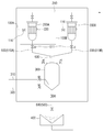
도 2는 본 발명의 바람직한 실시예에 따른 프로듀스드 워터 디-샌더 시스템을 나타낸 구성도.Figure 1 is a side view of a floating offshore structure (FPSO)
2 is a configuration view of a produced water de-sander system according to a preferred embodiment of the present invention.
본 명세서 및 청구범위에 사용된 용어나 단어는 통상적이거나 사전적인 의미로 한정 해석되지 아니하며, 발명자는 그 자신의 발명을 가장 최선의 방법으로 설명하기 위해 용어의 개념을 적절하게 정의할 수 있다는 원칙에 입각하여 본 발명의 기술적 사상에 부합하는 의미와 개념으로 해석되어야만 한다.It is to be understood that the words or words used in the present specification and claims are not to be construed in a conventional or dictionary sense and that the inventor can properly define the concept of a term in order to describe its invention in the best possible way And should be construed in light of the meanings and concepts consistent with the technical idea of the present invention.
이하, 첨부된 도 2를 참조하여 본 발명의 바람직한 실시예에 따른 프로듀스드 워터 디-샌더 시스템(이하, '디샌더 시스템'이라 함)에 대하여 설명하도록 한다.Hereinafter, a produced water de-sander system (hereinafter, referred to as a "de-sander system") according to a preferred embodiment of the present invention will be described with reference to FIG.
해저의 유정으로부터 시추된 원유(crude oil)는 오일뿐만 가스, 바닷물을 포함하게 된다.Crude oil drilled from the bottom of the seabed includes oil, gas and seawater.
이러한 원유는 오일 리저버(reservoir)에 저장된 후, 비중을 이용해 1차로 각각의 유체를 분리시킨다.This crude oil is stored in an oil reservoir, and then separates each fluid primarily using specific gravity.
즉, 비중이 높은 바닷물(produced water:프로듀스드 워터)은 리저버의 맨 밑에 위치되고, 프로듀스드 워터의 위로는 오일, 가스 등이 위치된다.That is, produced water is produced at the bottom of the reservoir and oil, gas and so on are placed on the top of the produced water.
이때, 오일과 가스는 오일 리저버의 일측에 설치된 별도의 장소로 배출된다.At this time, the oil and gas are discharged to a separate place provided on one side of the oil reservoir.
한편, 상기 오일 리저버에 남은 프로듀스드 워터에는 해저로부터 시추된 모래 및 각종 슬러리들이 포함되어 있는바 상기 모래 및 슬러리들을 분리하여 처리해야한다.Meanwhile, the produced water remaining in the oil reservoir contains sand drilled from the sea floor and various slurries, and the sand and slurry must be separated and treated.
이와 같은 모래 및 슬러리들은 각종 장비에 데미지를 줄 뿐만 아니라, 오일이 묻은 상태이므로 환경 오염에 심각한 영향을 줄 수 있기 때문이다.These sand and slurries not only damage various equipments, but they can also affect the environmental pollution because they are oiled.
이에 따라, 프로듀스드 워터는 해양구조물의 탑사이드에 설치된 디샌더 시스템을 이용하여 모래 및 슬러리를 분리하는 작업을 거치게 된다.As a result, the produced water is separated from the sand and slurry by using a desalter system installed on the top side of the offshore structure.
디샌더 시스템은 프로듀스드 워터에 포함된 모래 및 슬러리 등 솔리드 파티클(solid particle)를 분리하여 별도의 폐기 장소로 이동시키는 기술적 특징이 있다.The Desander system has the technical feature of separating solid particles, such as sand and slurry, from the produced water into separate disposal sites.
디샌더 시스템은 도 2에 도시된 바와 같이, 공급유로(100)와, 원심분리기(200)와, 어큐뮬레이터(300)와, 트레이(400)와, 수직유로(500)와 취합유로(600)를 포함하여 구성된다.2, the desalter system includes a supply passage 100, a centrifugal separator 200, an
공급유로(100)는 오일 리저버에서 분리된 프로듀스드 워터가 원심분리기(200)로 공급되는 유로이다.The supply channel 100 is a channel through which the produced water separated from the oil reservoir is supplied to the centrifugal separator 200.
이때, 공급유로(100) 상에는 공급유로(100)의 관로를 개폐하는 밸브(110)가 설치된다.At this time, a
다음으로, 원심분리기(200)는 공급유로(100)를 통해 공급된 프로듀스드 워터를 원심분리하여 모래 및 슬러리를 분리하는 역할을 한다.Next, the centrifugal separator 200 separates the sand and the slurry by centrifugally separating the produced water supplied through the supply channel 100.
이때, 원심분리기(200)의 상부에는 리퀴드 유로(210)가 설치된다.At this time, the
리퀴드 유로(210)는 원심분리기(200)에서 원심분리된 유체가 별도의 장소로 배출되는 관로이다.The
즉, 원심분리기(200)에 공급된 프로듀스드 워터가 원심분리되는 과정 중에는 원심력에 의해 유체와 모래로 분리되는데, 이 과정에서 분리된 유체가 배출되는 관로인 것이다.That is, during the process of centrifugal separation of the produced water supplied to the centrifugal separator 200, the fluid is separated into the fluid and the sand by the centrifugal force. In this process, the separated fluid is discharged.
이때, 상기 유체는 모래에 묻은 오일이 함유된 오일리(oily) 워터와, 원심분리기(200)의 내부 압력이 해소되면서 기화되는 가스로 분리된다.At this time, the fluid is separated into oily water containing oil adhered to the sand and gas which is evaporated while the internal pressure of the centrifuge 200 is released.
이때, 가스는 하이드로 카본(hydrocarbon) 등의 물질을 포함하며, 독성 및 폭발 위험을 야기할 수 있게 되므로, 리퀴드 유로(210)를 통해 배출되어야 한다.At this time, the gas contains hydrocarbons and the like, which may cause toxicity and explosion risk, and therefore must be discharged through the
그리고, 상기 원심분리기(200)의 일측에는 수위센서(220)가 설치된다.A
수위센서(220)는 공급유로(100)를 통해 공급되는 프로듀스드 워터의 수위를 제어하기 위함이다.The
즉, 공급유로(100)를 통해 원심분리기(200)의 내부로 일정량의 프로듀스드 워터가 차게 되면, 공급유로(100)의 밸브(110)를 차단하여 더 이상의 프로듀스드 워터 공급을 중단시키기 위한 것이다.That is, when a certain amount of produced water is charged into the centrifuge 200 through the supply passage 100, the
한편, 원심분리기(200)는 복수로 설치되되, 두 개로 설치됨이 바람직하며, 상기 원심분리기(200A,200B)는 병렬로 배치된다.Meanwhile, it is preferable that the centrifugal separator 200 is provided in a plurality of, but two
이는 서로 교번으로 모래 분리를 위한 동작이 이루어도록 함에 따라 각 장치의 과부하를 해소하여 장치에 무리를 발생하지 않을 수 있을 뿐만 아니라, 작업자의 안전사고를 예방할 수 있게 된다.As the operation for separating the sand is performed alternately, the overload of each device is solved, so that the device can be prevented from being overloaded and the safety accident of the worker can be prevented.
즉, 원심분리기(200)에서 프로듀스드 워터가 원심분리되면서 발생하는 하이드로 카본 등의 독성 물질로 인해 원심분리기(200) 주변은 유해물질에 노출될 수 있으므로, 유해물질이 해소되는 동안 다른 원심분리기(200)를 작동하여 작업의 연속성을 이어가도록 한 것이다.That is, the periphery of the centrifugal separator 200 may be exposed to harmful substances due to toxic substances such as hydrocarbons generated during centrifugal separation of the produced water in the centrifugal separator 200, 200) to operate continuously.
한편, 공급유로(100)는 분기되어 각각의 원심분리기(200)에 연결되며, 프로듀스드 워터의 공급은 밸브(110)에 의해 제어된다.On the other hand, the supply passage 100 is branched and connected to each of the centrifuges 200, and the supply of the produced water is controlled by the
다음으로, 어큐뮬레이터(300)는 원심분리기(200)로부터 분리된 모래 및 슬러리를 수용하여 세척시킨 후 트레이(400)로 내보내는 역할을 한다.Next, the
상기 어큐뮬레이터(300)는 원심분리기(200)의 하방에 배치되며, 한 개만 설치된다.The
즉, 원심분리기(200)와 어큐뮬레이터(300)는 버티컬 타입으로 설치될 뿐만 아니라 한 개만 설치되므로, 설치 공간에 대한 효율성을 높일 수 있게 된다.That is, since the centrifugal separator 200 and the
특히, 원유 분리작업에 대한 컨트롤이 심플하게 이루어질 수 있게 된다.In particular, control over the crude oil separation operation can be made simple.
이때, 어큐뮬레이터(300)의 내부에는 일정량의 물이 저수되며, 저수된 물로 인해 원심분리기(200)로부터 낙하된 모래의 낙하속도를 감속시킴과 동시에 모래에 대한 세척 역할을 하게 된다.At this time, a certain amount of water is stored in the
이러한 물의 저수 및 배수를 위해 어큐뮬레이터(300)의 일측에는 유입유로(310) 및 배출유로(320)가 설치된다.An
다음으로, 트레이(400)는 어큐뮬레이터(300)에 수용된 모래를 수집하여 별도의 장소로 처리하는 역할을 하며, 어큐뮬레이터(300)의 하방에 설치된다.Next, the
이때, 트레이(400)는 모래 수집을 위한 일정 공간을 형성하는 구성이면 무방하다.At this time, the
다음으로, 수직유로(500)는 원심분리기(200)에서 분리된 모래가 하방의 트레이(400)까지 배출되기 위한 관로 역할을 하며, 원심분리기(200)와 어큐뮬레이터(300) 사이에 설치된 제1수직유로(510)와, 어큐뮬레이터(300)와 트레이(400) 사이에 설치된 제2수직유로(520)로 구성된다.The
제1수직유로(510)는 원심분리기(200) 각각의 하방에 설치되며, 원심분리기(200)로부터 분리된 모래를 어큐뮬레이터(300)로 내보내는 유로이며, 제2수직유로(520)는 어큐뮬레이터(300)를 통해 처리된 모래나 슬러리를 트레이(400)로 내보내기 위한 유로이다.The first vertical channel 510 is disposed below each of the centrifuges 200 and is a channel for discharging the sand separated from the centrifugal separator 200 to the
즉, 원심분리기(200)와 어큐뮬레이터(300)의 배치구조는 버티컬 타입으로 제공되는바, 분리된 모래는 자중에 의해 낙하되는데, 수직유로(500)는 자중에 의해 낙하되는 모래를 가이드하는 관로인 것이다.That is, the arrangement structure of the centrifugal separator 200 and the
이때, 각각의 제1수직유로(510)에는 자동밸브(511)가 설치되며, 자동밸브(511)는 작동되는 원심분리기(200)의 제1수직유로(510)만 개방될 수 있도록 제어한다.At this time, an
다음으로, 취합유로(600)는 각 원심분리기(200)의 제1수직유로(510)와 어큐뮬레이터(300)를 연결하며, 분기된 제1수직유로(510)를 취합하여 하나의 유로를 형성한다.Next, the collecting
즉, 취합유로(600)는 원심분리기(200)가 교번으로 작동되는 과정에서 분리된 모래를 어큐뮬레이터(300)에 유입시키는 관로로서, 취합유로(600)는 개방된 제1수직유로(510)로부터 배출되는 모래를 어큐뮬레이터(300)에 유입시키는 관로인 것이다.That is, the collecting
이하, 상기한 구성으로 이루어진 디샌더 시스템의 작동에 대하여 설명하도록 한다.Hereinafter, the operation of the dig sander system constructed as described above will be described.
공급유로(100A)가 개방되고, 상기 공급유로(100A)를 통해 오일 리저버로부터 어느 하나의 원심분리기(200A)로 프로듀스드 워터가 공급된다.The
이때, 다른 하나의 원심분리기(200B)로 통하는 분기된 공급유로(100B)는 폐쇄된 상태이다.At this time, the branched
이후, 수위센서(220)는 원심분리기(200A) 내로 차오르는 프로듀스드 워터의 수위를 감지하여 일정량의 프로듀스드 워터가 공급되면 공급유로(100A)를 폐쇄시킨다.The
이후, 원심분리기(200A) 내로 유입된 프로듀스드 워터는 접선 방향의 속도(tangential velocity)로 변환된다.Thereafter, the produced water introduced into the
이후, 프로듀스드 워터는 하부로 갈수록 점점 좁아지는 원심분리기(200A)의 하류로 이동하면서 접선 방향의 속도 및 원심력은 증가하게 된다.Thereafter, the produced water moves to the downstream side of the
이때, 원심분리기(200A)의 내부는 고압의 상태가 되며, 비중이 큰 모래 및 슬러리 등은 더 큰 원심력을 받게 되어 원심분리기(200A)의 내주면 측으로 이동하게 되고 비중이 작은 오일리 워터는 원심분리기(200A)의 중앙으로 모이게 된다.At this time, the interior of the
이후, 원심분리기(200A)의 내주면 측으로 밀려난 모래 및 슬러리는 제1수직유로(510A)를 통해 배출되어 취합유로(600)를 통해 원심분리기(200) 하방의 어큐뮬레이터(300)로 낙하된다.The sand and the slurry pushed to the inner circumferential surface of the
이때, 오일리 워터는 리퀴드 유로(210)를 통해 배수된다.At this time, the oily water is drained through the
이때, 오일리 워터가 배수되는 과정에서, 원심분리기(200A) 내부의 압력은 배압(back pressure)되는데, 이 과정에서 오일이 기화되면서 하이드로 카본 등의 유해 가스가 발생하게 된다.At this time, in the process of draining the oily water, the pressure inside the
상기 유해가스 역시 리퀴드 유로(210)를 통해 배출되며, 별도의 장소에서 제거(degassing)된다.The noxious gas is also discharged through the
한편, 모래 및 슬러리는 관성에 의해 원심력의 속도를 유지한 채로 어큐뮬레이터(300)에 낙하되는데, 모래 및 슬러리는 어큐뮬레이터(300)에 채워진 물에 의해 낙하속도가 감소되며, 비중에 의해 어큐뮬레이터(300)의 하부에 적재된다.On the other hand, the sand and the slurry fall on the
이후, 어큐뮬레이터(300)의 배출유로(320)를 개방하여 유체를 배수시키고, 제2수직유로(520)를 개방하여 모래 및 슬러리를 트레이(400)로 낙하시킨다.Thereafter, the
이후, 모래 및 슬러리는 트레이(400)에 수집되어 온 쇼어로 운반된 후, 별도의 처리기관으로 보내져 처리된다.The sand and slurry are then conveyed to a shore collected in
한편, 상기한 일련의 분리작업이 이루어진 후, 분리작업을 지속적으로 수행하기 위해서는 일측의 시스템으로 전환(change over)시킨다.Meanwhile, after the above-described series of separating operations are performed, in order to continuously perform the separating operation, the system is changed over to one side.
이는, 전술한 바와 같이, 시스템의 과부하를 방지하고 원심분리기(200) 주변의 유해가스를 해소하여 작업자의 안전을 도모하기 위함이다.This is to prevent the overload of the system and to eliminate the harmful gas around the centrifuge 200 as described above so as to secure the safety of the operator.
즉, 유해가스가 해소될 때까지, 하나의 시스템을 중단하는 동안 일측의 시스템을 가동함으로써 분리작업의 연속성을 유지할 수 있는 것이다.That is, the continuity of the separation operation can be maintained by operating one side system while one system is stopped until the harmful gas is dissolved.
이를 위해서는 폐쇄되어 있던 분기된 공급유로(100B)를 개방하여 프로듀스드 워터를 다른 하나의 원심분리기(200B)로 유입시킨다.For this purpose, the branched
이때, 작동이 정지된 어느 하나의 원심분리기(200A)로 통하는 공급유로(100A)는 폐쇄시킨다.At this time, the
이후, 전술한 일련의 작업을 통해 분리된 모래는 제1수직유로(510B)를 통해 취합유로(600)를 거쳐 어큐뮬레이터(300)로 유입된다.Thereafter, the sand separated through the series of operations described above flows into the
이때, 제1수직유로(510B)에 설치된 자동밸브(511)는 자동으로 개방되어 어큐뮬레이터(300)로의 모래 배출을 제어한다.At this time, the
이후, 어큐뮬레이터(300)에서 처리된 모래는 제2수직유로(520)를 통해 트레이(400)로 배출되어 온 쇼어로 보내진 후 처리된다.Thereafter, the sand processed in the
지금까지 설명한 바와 같이, 본 발명에 따른 프로듀스드 워터 디샌더 시스템은 시추된 원유에 포함된 모래 및 슬러리 등을 분리하여 제거함으로써 모래 등으로 인한 장비 고장을 방지할 수 있으며 정제된 오일의 품질을 높일 수 있는 기술적 특징이 있다.As described above, the produced water desalter system according to the present invention can prevent the equipment failure due to sand or the like by separating and removing the sand and slurry contained in the drilled crude oil, thereby improving the quality of the refined oil There are technical features that can be.
또한, 버티컬 타입으로 제공되며, 어큐뮬레이터가 한 개만 설치됨에 따라, 설치 공간에 대한 효율성을 높이고 컨트롤 작업을 심플하게 할 수 있다. In addition, it is provided as a vertical type, and as only one accumulator is installed, the efficiency of installation space can be increased and the control work can be simplified.
이상에서 본 발명은 기재된 구체예에 대하여 상세히 설명되었지만 본 발명의 기술사상 범위 내에서 다양한 변형 및 수정이 가능함은 당업자에게 있어서 명백한 것이며, 이러한 변형 및 수정은 첨부된 특허 청구범위에 속함은 당연한 것이다.While the present invention has been particularly shown and described with reference to exemplary embodiments thereof, it is evident that many alternatives, modifications and variations will be apparent to those skilled in the art.
100 : 공급유로 200(200A,200B) : 원심분리기
210 : 리퀴드 유로 300 : 어큐뮬레이터
400 : 트레이 500 : 수직유로
510(510A,510B) : 제1수직유로 520 : 제2수직유로
600 : 취합유로100: Supply flow path 200 (200A, 200B): Centrifuge
210: Liquid passage 300: Accumulator
400: Tray 500: Vertical channel
510 (510A, 510B): first vertical channel 520: second vertical channel
600: Collecting Euro
Claims (5)
오일 리저버로부터 프로듀스드 워터가 공급되는 공급유로;
상기 공급유로에 연결되며, 프로듀스드 워터를 원심분리하는 복수의 원심분리기;
상기 원심분리기의 하방에 설치되며, 원심분리기로부터 분리된 모래를 저장하는 하나의 어큐뮬레이터;
상기 어큐뮬레이터의 하방에 설치되며, 어큐뮬레이터의 모래를 수집하는 트레이;
상기 각각의 원심분리기에 설치되며, 어큐뮬레이터로 모래가 낙하되는 관로를 형성하는 복수의 제1수직유로;
상기 복수의 제1수직유로와 어큐뮬레이터 사이에 설치된 하나의 취합유로;
상기 각각의 제1수직유로에 설치된 자동밸브;
상기 어큐뮬레이터와 트레이 사이에 설치되며, 자중에 의해 모래가 낙하되는 관로를 형성하는 제2수직유로:를 포함하여 구성된 프로듀스드 워터 디-샌더 시스템.1. An oil reservoir for separating and storing gas, oil, and produced water using a specific gravity of crude oil drilled from the sea floor,
A supply passage through which the produced water is supplied from the oil reservoir;
A plurality of centrifuges connected to the supply passage for centrifugally separating the produced water;
An accumulator installed below the centrifugal separator and storing sand separated from the centrifugal separator;
A tray installed below the accumulator for collecting sand of the accumulator;
A plurality of first vertical channels provided in the respective centrifuges and forming a channel through which the sand is dropped by the accumulator;
One collecting flow path provided between the plurality of first vertical flow paths and the accumulator;
An automatic valve installed in each of the first vertical flow paths;
And a second vertical flow path provided between the accumulator and the tray, the second vertical flow path forming a channel through which sand is dropped by its own weight.
상기 원심분리기의 상부에는 원심분리된 오일리 워터(oily water) 및 가스가 배출되는 리퀴드 유로가 설치된 것을 특징으로 하는 프로듀스드 워터 디-샌더 시스템.The method according to claim 1,
Wherein a centrifugal oily water and a liquid flow path through which gas is discharged are installed on the upper portion of the centrifugal separator.
상기 어큐뮬레이터의 내부에는 원심분리로부터 배출된 모래의 유속을 감속시키기 위한 액체가 저수된 것을 특징으로 하는 프로듀스드 워터 디-샌더 시스템.3. The method according to claim 1 or 2,
Wherein a liquid for decelerating the flow rate of the sand discharged from the centrifugal separator is stored in the accumulator.
상기 원심분리기는 병렬로 배치된 것을 특징으로 하는 프로듀스드 워터 디-샌더 시스템.3. The method according to claim 1 or 2,
Wherein the centrifuges are arranged in parallel.
상기 원심분리기에는 공급유로를 통해 유입된 프로듀스드 워터의 수위를 감지하는 수위센서가 설치된 것을 특징으로 하는 프로듀스드 워터 디-샌더 시스템.
3. The method according to claim 1 or 2,
Wherein the centrifugal separator is provided with a water level sensor for sensing the water level of the produced water flowing through the supply channel.
Priority Applications (1)
| Application Number | Priority Date | Filing Date | Title |
|---|---|---|---|
| KR1020120146144A KR20140077384A (en) | 2012-12-14 | 2012-12-14 | Produced water de-sander system |
Applications Claiming Priority (1)
| Application Number | Priority Date | Filing Date | Title |
|---|---|---|---|
| KR1020120146144A KR20140077384A (en) | 2012-12-14 | 2012-12-14 | Produced water de-sander system |
Publications (1)
| Publication Number | Publication Date |
|---|---|
| KR20140077384A true KR20140077384A (en) | 2014-06-24 |
Family
ID=51129326
Family Applications (1)
| Application Number | Title | Priority Date | Filing Date |
|---|---|---|---|
| KR1020120146144A Withdrawn KR20140077384A (en) | 2012-12-14 | 2012-12-14 | Produced water de-sander system |
Country Status (1)
| Country | Link |
|---|---|
| KR (1) | KR20140077384A (en) |
Cited By (1)
| Publication number | Priority date | Publication date | Assignee | Title |
|---|---|---|---|---|
| CN109695444A (en) * | 2019-02-03 | 2019-04-30 | 四川乐山伟业机电有限责任公司 | A kind of compound desander |
-
2012
- 2012-12-14 KR KR1020120146144A patent/KR20140077384A/en not_active Withdrawn
Cited By (2)
| Publication number | Priority date | Publication date | Assignee | Title |
|---|---|---|---|---|
| CN109695444A (en) * | 2019-02-03 | 2019-04-30 | 四川乐山伟业机电有限责任公司 | A kind of compound desander |
| CN109695444B (en) * | 2019-02-03 | 2024-02-27 | 四川乐山伟业机电有限责任公司 | Duplex sand remover |
Similar Documents
| Publication | Publication Date | Title |
|---|---|---|
| US4846780A (en) | Centrifuge processor and liquid level control system | |
| EP2176517B1 (en) | Systems and methods for separating hydrocarbons from water | |
| US6872239B2 (en) | Method and a system for separating a mixture | |
| DK179274B1 (en) | Split flow pipe separator | |
| EA037695B1 (en) | Oil, water, gas and solid particle separation in oil and/or gas production | |
| NO315971B1 (en) | Method and apparatus plus separator for separating liquid from solid material | |
| KR101036621B1 (en) | Drain processing unit | |
| CN203754466U (en) | Floating circulation oil, suspension and sludge receiving and discharging device | |
| US10633962B2 (en) | Method and system for subsea separation of produced water | |
| NO318754B1 (en) | Apparatus and method for separating water from an oil mixture extracted from a well | |
| JP2014512469A (en) | Apparatus and method for taking out solid matter in water bottom | |
| US20180073343A1 (en) | Method and System for Subsea Purification of Produced Water From Subsea Oil Producing Installations | |
| KR20140057065A (en) | Produced Water D-Sander System | |
| KR20140077384A (en) | Produced water de-sander system | |
| KR20140077388A (en) | Produced water de-sander system | |
| KR102003401B1 (en) | Waste oil and Water Separation System and Pretreatment Apparatus of the Separation System | |
| NO20120521A1 (en) | Underwater separation systems | |
| KR20130071740A (en) | Skimmer tank to separate drilling mud | |
| KR101774773B1 (en) | Separator for multiphase mixture | |
| KR200479288Y1 (en) | Drain water recycling system of drillship and recyling method thereof | |
| KR101572442B1 (en) | Degassing device having oil re-saparaton function | |
| KR101541313B1 (en) | Drain seperation system for drillship | |
| KR20250000138A (en) | Oil-Water Separation Accelerator | |
| KR101511212B1 (en) | Desander in subsea pipeline | |
| KR20160001898U (en) | Marine Plant Drain Apparatus with Coalescer |
Legal Events
| Date | Code | Title | Description |
|---|---|---|---|
| PA0109 | Patent application |
Patent event code: PA01091R01D Comment text: Patent Application Patent event date: 20121214 |
|
| PG1501 | Laying open of application | ||
| PC1203 | Withdrawal of no request for examination | ||
| WITN | Application deemed withdrawn, e.g. because no request for examination was filed or no examination fee was paid |