KR20140077413A - Solar Combiner Box for photovoltaic power generator with sealing type casing - Google Patents
Solar Combiner Box for photovoltaic power generator with sealing type casing Download PDFInfo
- Publication number
- KR20140077413A KR20140077413A KR1020120146207A KR20120146207A KR20140077413A KR 20140077413 A KR20140077413 A KR 20140077413A KR 1020120146207 A KR1020120146207 A KR 1020120146207A KR 20120146207 A KR20120146207 A KR 20120146207A KR 20140077413 A KR20140077413 A KR 20140077413A
- Authority
- KR
- South Korea
- Prior art keywords
- casing
- connection
- heat
- power generator
- photovoltaic power
- Prior art date
- Legal status (The legal status is an assumption and is not a legal conclusion. Google has not performed a legal analysis and makes no representation as to the accuracy of the status listed.)
- Ceased
Links
- 238000007789 sealing Methods 0.000 title 1
- 230000017525 heat dissipation Effects 0.000 claims description 14
- 238000000034 method Methods 0.000 claims description 4
- 239000000428 dust Substances 0.000 abstract description 4
- 150000003839 salts Chemical class 0.000 abstract description 4
- 238000010248 power generation Methods 0.000 description 3
- 238000010586 diagram Methods 0.000 description 2
- 230000000694 effects Effects 0.000 description 2
- 230000007257 malfunction Effects 0.000 description 2
- 238000003491 array Methods 0.000 description 1
- 238000001816 cooling Methods 0.000 description 1
- 238000009434 installation Methods 0.000 description 1
- 239000000126 substance Substances 0.000 description 1
- XLYOFNOQVPJJNP-UHFFFAOYSA-N water Substances O XLYOFNOQVPJJNP-UHFFFAOYSA-N 0.000 description 1
- 238000003466 welding Methods 0.000 description 1
Images


Classifications
-
- H—ELECTRICITY
- H02—GENERATION; CONVERSION OR DISTRIBUTION OF ELECTRIC POWER
- H02B—BOARDS, SUBSTATIONS OR SWITCHING ARRANGEMENTS FOR THE SUPPLY OR DISTRIBUTION OF ELECTRIC POWER
- H02B1/00—Frameworks, boards, panels, desks, casings; Details of substations or switching arrangements
- H02B1/56—Cooling; Ventilation
-
- H—ELECTRICITY
- H02—GENERATION; CONVERSION OR DISTRIBUTION OF ELECTRIC POWER
- H02B—BOARDS, SUBSTATIONS OR SWITCHING ARRANGEMENTS FOR THE SUPPLY OR DISTRIBUTION OF ELECTRIC POWER
- H02B1/00—Frameworks, boards, panels, desks, casings; Details of substations or switching arrangements
- H02B1/26—Casings; Parts thereof or accessories therefor
-
- Y—GENERAL TAGGING OF NEW TECHNOLOGICAL DEVELOPMENTS; GENERAL TAGGING OF CROSS-SECTIONAL TECHNOLOGIES SPANNING OVER SEVERAL SECTIONS OF THE IPC; TECHNICAL SUBJECTS COVERED BY FORMER USPC CROSS-REFERENCE ART COLLECTIONS [XRACs] AND DIGESTS
- Y02—TECHNOLOGIES OR APPLICATIONS FOR MITIGATION OR ADAPTATION AGAINST CLIMATE CHANGE
- Y02E—REDUCTION OF GREENHOUSE GAS [GHG] EMISSIONS, RELATED TO ENERGY GENERATION, TRANSMISSION OR DISTRIBUTION
- Y02E10/00—Energy generation through renewable energy sources
- Y02E10/50—Photovoltaic [PV] energy
Landscapes
- Engineering & Computer Science (AREA)
- Power Engineering (AREA)
- Cooling Or The Like Of Electrical Apparatus (AREA)
Abstract
태양광 발전장치용 접속반은, 내부에 접속반 구성품을 수용하는 밀폐형 케이싱, 및 케이싱의 적어도 일 부위에 형성되며 다수의 방열핀을 구비한 방열부를 구비한다. 방열부는 상기 케이싱의 상면에 형성된다. 접속반 내로의 외부 공기 유입이 차단되므로 유입되는 공기 내의 먼지나 염분에 의한 접속반 구성품의 손상이 방지되면서도 접속반 구성품에서 발생되는 열의 방열이 이루어져 내구성이 증대되고 안정적인 동작이 가능하다.The connecting panel for a solar power generating device has a closed casing for accommodating the connecting component parts therein and a heat radiating part formed on at least one part of the casing and including a plurality of radiating fins. The heat radiating portion is formed on the upper surface of the casing. Since the inflow of external air into the connection panel is blocked, it is possible to prevent the damage of the connection component due to the dust or salt in the inflow air, and to dissipate the heat generated from the connection component, thereby increasing the durability and enabling stable operation.
Description
본 발명은 태양광 발전장치용 접속반에 관한 것으로서, 보다 상세하게는, 태양전지(모듈)을 구비한 태양광 발전 시스템과 전력변환기(태양광 인버터) 사이에 설치되는 접속반에 관한 것이다.BACKGROUND OF THE INVENTION 1. Field of the Invention The present invention relates to a connection panel for a photovoltaic device, and more particularly, to a connection panel installed between a photovoltaic power generation system having a solar cell (module) and a power converter (solar inverter).
태양광 발전장치는 태양으로부터 입사되는 빛에너지를 전기에너지로 전환하기 위한 장치로서, 태양전지(모듈)을 구비한 발전 시스템과 접속반 및 전력변환기(태양광 인버터)를 구비하고 있다. 접속반은 태양전지(모듈)과 전력변환기(태양광 인버터) 사이에 설치되어 많은 수의 태양전지 어레이에서 발생된 전력을 모으는 역할을 수행하며, 각 어레이간의 역류방지 및 각 어레이의 과전류방지 기능이 있고 또한 각 어레이의 동작 상태를 확인할 수 있는 기능과 접속된 전체 전력을 ON/OFF 하는 기능을 수행한다.A photovoltaic power generation device is a device for converting light energy incident from the sun into electric energy, and is provided with a power generation system having a solar cell (module), a connection panel, and a power converter (solar inverter). The connection board is installed between the solar cell (module) and the power converter (solar inverter), collects the power generated by a large number of solar cell arrays, and prevents reverse flow between each array and prevents overcurrent of each array It also has a function to check the operation status of each array and a function to turn on / off all connected power.
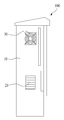
도 1 은 종래의 일반적인 접속반의 외관 구성을 도시한 것이다. 도 1 과 같이, 종래의 접속반(100)은 그 내부에 각종 회로장치가 설치된 접속반 구성품(도시되지 않음)이 구비되고 이러한 접속반 구성품은 케이싱(10)에 수용되어 보호된다. 접속반(100)은 내부 접속반 구성품의 동작에 의해 열이 발생하는데, 발생된 열을 배출하기 위하여 측방에는 공기흡입구(20)가 마련되어 있고 또한 공기흡입구(20)를 통해 강제로 공기가 흡입되어 내부 접속반 구성품을 냉각시키고 배출되도록 하기 위하여 팬(30)이 마련되어 있다. 도 2 에서 미설명 부호 40 은 접속반(100)의 동작을 조작하기 위한 조작패널이다.Fig. 1 shows the appearance of a conventional connecting board. As shown in Fig. 1, a
이러한 구조의 종래의 접속반(100)은 내부 접속반 구성품을 냉각시키기 위한 공기흡입구(20)와 팬(30)의 구성에 의하여 가혹한 설치 환경에서 많은 문제점을 야기하고 있다. 즉, 접속반(100)이 설치되는 환경은 태양광이 강한 야외나 바닷가로서, 이러한 환경은 먼지가 많거나 또는 공기 내에 염분을 다량 함유한 수분이 함유되어 있다. 따라서 먼지가 많은 환경에서는 접속반 구성품에 이물질이 적층될 수 있고 염분이 많은 환경에서는 접속반 구성품의 부식이 유발되어, 접속반(100)의 수명이 현저하게 단축된다.The
따라서 접속반(100)의 오동작을 방지하고 내구성을 보장하기 위해서는 외부의 공기 유입이 차단되도록 케이싱(10)이 밀폐형으로 구성되는 것이 바람직하나, 이 경우 내부 접속반 구성품의 방열이 불가능하게 되어 접속반 구성품의 오동작 또는 파손이 유발될 수 있다.Therefore, in order to prevent malfunction of the
본 발명은 상기와 같은 문제점을 해결하기 위해 안출된 것으로서, 본 발명의 목적은, 접속반 내로의 외부 공기 유입이 차단되도록 하여 접속반의 내구성을 증대시키면서도 내부 접속반 구성품의 발열에 대한 방열이 용이하게 이루어지도록 하는 방안을 제공하는 것이다.SUMMARY OF THE INVENTION The present invention has been conceived to solve the problems as described above, and it is an object of the present invention to provide an air conditioner which is capable of preventing external air inflow into the connection compartment to increase the durability of the connection compartment, And to provide a method for realizing this.
상기 목적을 달성하기 위하여 본 발명은, 내부에 접속반 구성품을 수용하는 밀폐형 케이싱; 및 상기 케이싱의 적어도 일 부위에 형성되며, 다수의 방열핀을 구비한 방열부;를 포함하는 것을 특징으로 하는 태양광 발전장치용 접속반을 제안한다.According to an aspect of the present invention, there is provided an electronic apparatus comprising: a closed casing for accommodating therein a connection component; And a heat dissipating unit formed on at least one portion of the casing and having a plurality of heat dissipating fins.
상기 방열부는 상기 케이싱의 상면에 형성되는 것이 바람직하다.The heat dissipating unit is preferably formed on the upper surface of the casing.
본 발명에 따르면, 접속반 내로의 외부 공기 유입이 차단되므로 유입되는 공기 내의 먼지나 염분에 의한 접속반 구성품의 손상이 방지되면서도 접속반 구성품에서 발생되는 열의 방열이 이루어져 내구성이 증대되고 안정적인 동작이 가능하다.According to the present invention, since the inflow of external air into the connection half is blocked, the connection half component is prevented from being damaged by the dust or salt in the inflow air, and the heat generated from the connection half component is dissipated to increase the durability and stable operation Do.
도 1 및 도 2 는 종래의 일반적인 태양광 발전장치용 접속반의 외관을 도시한 도면.
도 3 및 도 4 는 본 발명에 따른 태양광 발전장치용 접속반의 외관을 도시한 도면.
도 5 는 도 4 의 상면을 도시한 도면.BRIEF DESCRIPTION OF THE DRAWINGS Fig. 1 and Fig. 2 are diagrams showing an appearance of a conventional connection unit for a general photovoltaic device. Fig.
FIG. 3 and FIG. 4 are diagrams showing an appearance of a connection panel for a solar power generator according to the present invention. FIG.
Fig. 5 is a top view of Fig. 4; Fig.
이하에서는 본 발명의 바람직한 실시예들을 도면을 참조하여 보다 구체적으로 설명한다.Hereinafter, preferred embodiments of the present invention will be described in detail with reference to the drawings.
도 3 내지 도 5 는 본 발명에 따른 태양광 발전장치용 접속반을 도시한 도면이다.3 to 5 are views showing a connection panel for a solar power generator according to the present invention.
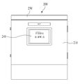
접속반(200)은 그 내부에 각종 회로장치가 설치된 접속반 구성품(도시되지 않음)이 구비되고 이러한 접속반 구성품은 케이싱(210)에 수용되어 보호된다. 본 발명에서 케이싱(210)은 밀폐형으로 구성된다. 즉, 케이싱(210)은 내부 공간으로 공기가 유입될 수 없는 구조로 구성되어 케이싱(210) 내의 공간이 외부 공간과 단절되도록 하며, 바람직하게는 기밀적으로 폐쇄되도록 구성된다. 케이싱(210) 자체를 기밀적으로 구성하는 방법으로는 필요에 따라 다양한 방식이 채용될 수 있으며, 이는 주지관용의 것이므로 구체적인 기재는 생략한다.The
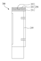
케이싱(210)의 상면에는 방열부(250)가 설치되어 있다. 방열부(250)는 저면을 구성하는 방열판(251)과 방열판(251)상에 돌출되도록 형성된 다수의 방열핀(252)으로 구성된다. 방열판(251)과 방열핀(252)은 일체로 형성될 수도 있고 방열핀(252)이 개별 제작되어 방열판(251)상에 용접 등에 의해 부착될 수도 있다.On the upper surface of the
방열판(251)은 케이싱(210) 상면의 전체 면적에 부합되도록 형성되어 상면에 면접촉되며, 이에 따라 케이싱(210) 상면을 통해 케이싱(210) 내의 열이 방열판(251)에 전달된다. 방열핀(252)은 방열판(251)에 외부의 공기에 접촉되는 면적을 넓혀 전달된 열의 방열 면적을 넓히는 기능을 하여 한다. 방열핀(252)은 도 5 에 도시된 바와 같이 플레이트의 형상으로 형성될 수도 있고, 다수의 핀 형태로 구성될 수도 있다. 방열핀(252)의 형상과 구조 또는 개수 등은 필요에 따라 다양하게 변형될 수 있음은 자명하다. 미설명 도면부호 240 은 접속반(200)의 동작을 조작하기 위한 조작패널이다.The
한편, 방열부(250)는 본 실시예에서와 같이 케이싱(210)의 상면에 설치될 수도 있고, 케이싱(210)의 측면 또는 배면 등과 같이 타 부분에 설치될 수도 있다. 그러나, 접속반(200)이 주로 외부 환경에 설치됨을 고려할 때, 공기의 유동 속도가 빠른 상면에 설치되는 것이 좁은 면적에 방열부(250)를 설치하여도 방열 효과가 가장 넓은 효과가 있다.The
이와 같은 구조의 본 발명에 의하면, 케이싱(210)이 기밀적인 밀폐 구조를 구비하므로 외부의 공기가 케이싱(210) 내로 유입되지 않는다. 따라서 가혹한 외부 환경에서도 먼지나 염분에 의한 접속반 구성품의 손상이 발생하지 않아 접속반(200)의 내구성이 증대된다. 이때 접속반 구성품의 동작에 의해 발생하는 열은 케이싱(210)을 통해 방열부(250)에 전달되어 방열되므로, 별도의 공기흡입구나 팬 없이도 방열 효과를 얻을 수 있다. 나아가 본 발명에 따르면, 간단한 구조의 방열부(250)를 부착하기만 하면 되므로, 종래의 기술에서와 같이 별도의 공기흡입구를 형성하거나 팬을 부착하고 동력을 공급하는 구성이 필요하지 않으며, 따라서 제작비가 현저하게 절감된다는 이점이 있다.According to the present invention having such a structure, since the
Claims (2)
내부에 접속반 구성품을 수용하는 밀폐형 케이싱; 및
상기 케이싱의 적어도 일 부위에 형성되며, 다수의 방열핀을 구비한 방열부;
를 포함하는 것을 특징으로 하는 태양광 발전장치용 접속반.
1. A connection panel for a photovoltaic device,
CLAIMS What is claimed is: 1. An enclosure comprising: And
A heat dissipation unit formed on at least one portion of the casing and including a plurality of heat dissipation fins;
And a connection unit for the photovoltaic device.
상기 방열부는 상기 케이싱의 상면에 형성되는 것을 특징으로 하는 태양광 발전장치용 접속반.The method according to claim 1,
Wherein the heat dissipating unit is formed on an upper surface of the casing.
Priority Applications (1)
| Application Number | Priority Date | Filing Date | Title |
|---|---|---|---|
| KR1020120146207A KR20140077413A (en) | 2012-12-14 | 2012-12-14 | Solar Combiner Box for photovoltaic power generator with sealing type casing |
Applications Claiming Priority (1)
| Application Number | Priority Date | Filing Date | Title |
|---|---|---|---|
| KR1020120146207A KR20140077413A (en) | 2012-12-14 | 2012-12-14 | Solar Combiner Box for photovoltaic power generator with sealing type casing |
Publications (1)
| Publication Number | Publication Date |
|---|---|
| KR20140077413A true KR20140077413A (en) | 2014-06-24 |
Family
ID=51129353
Family Applications (1)
| Application Number | Title | Priority Date | Filing Date |
|---|---|---|---|
| KR1020120146207A Ceased KR20140077413A (en) | 2012-12-14 | 2012-12-14 | Solar Combiner Box for photovoltaic power generator with sealing type casing |
Country Status (1)
| Country | Link |
|---|---|
| KR (1) | KR20140077413A (en) |
Cited By (4)
| Publication number | Priority date | Publication date | Assignee | Title |
|---|---|---|---|---|
| CN104779531A (en) * | 2015-04-29 | 2015-07-15 | 无锡阿比利德电力科技有限公司 | Electric control cabinet for three box type zonal-structure oil field |
| KR101600962B1 (en) * | 2015-07-01 | 2016-03-08 | 탑솔라(주) | Junction box for photovoltaic module |
| CN109728511A (en) * | 2019-01-10 | 2019-05-07 | 人民电器集团上海有限公司 | A convenient combination of substation protective shell |
| KR20200124451A (en) | 2019-04-24 | 2020-11-03 | 임명수 | Heat release apparatus for combiner box in solar power generating system |
-
2012
- 2012-12-14 KR KR1020120146207A patent/KR20140077413A/en not_active Ceased
Cited By (4)
| Publication number | Priority date | Publication date | Assignee | Title |
|---|---|---|---|---|
| CN104779531A (en) * | 2015-04-29 | 2015-07-15 | 无锡阿比利德电力科技有限公司 | Electric control cabinet for three box type zonal-structure oil field |
| KR101600962B1 (en) * | 2015-07-01 | 2016-03-08 | 탑솔라(주) | Junction box for photovoltaic module |
| CN109728511A (en) * | 2019-01-10 | 2019-05-07 | 人民电器集团上海有限公司 | A convenient combination of substation protective shell |
| KR20200124451A (en) | 2019-04-24 | 2020-11-03 | 임명수 | Heat release apparatus for combiner box in solar power generating system |
Similar Documents
| Publication | Publication Date | Title |
|---|---|---|
| JP6209790B2 (en) | Electronic component housing with heat sink | |
| WO2017101679A1 (en) | Tray, power battery pack and electric vehicle | |
| TWI723001B (en) | Photovoltaic modules including external bypass diodes and assembly comprising the same | |
| CN101583255A (en) | Electronic equipment chassis | |
| KR20140077413A (en) | Solar Combiner Box for photovoltaic power generator with sealing type casing | |
| US8611091B2 (en) | Thermal module for solar inverter | |
| EP4333583A1 (en) | Heat dissipation apparatus and device | |
| CN201360124Y (en) | Junction box for solar photovoltaic power generation system | |
| EP4646047A1 (en) | Inverter | |
| KR101666147B1 (en) | Radiation apparatus for combiner in solar power generating system | |
| KR101000313B1 (en) | Fastening Structure of Solar Small Capacity Inverter | |
| CN210298342U (en) | Power supply system | |
| KR101642966B1 (en) | The connector band for photovoltaic power system | |
| CN220545325U (en) | Outdoor cabinet | |
| CN216161719U (en) | Semiconductor packaging structure | |
| KR102001029B1 (en) | Dissipation Module Using Peltier Devices With Diode Module On Connection Board For Solar Power Generation In Outer Case | |
| KR20200124451A (en) | Heat release apparatus for combiner box in solar power generating system | |
| CN222300256U (en) | Quick radiating LED display screen backlight unit | |
| CN222916478U (en) | High-efficient heat dissipation type LED display screen power | |
| CN216133612U (en) | Outdoor LED display screen protector | |
| CN223623013U (en) | Photovoltaic control box and refrigeration equipment | |
| CN222017095U (en) | Wall-mounted power supply module | |
| JP6203693B2 (en) | Electrical equipment | |
| JP6448402B2 (en) | Connection box for photovoltaic power generation | |
| TWI435506B (en) | A junction box and a solar module assembly including the same |
Legal Events
| Date | Code | Title | Description |
|---|---|---|---|
| PA0109 | Patent application |
Patent event code: PA01091R01D Comment text: Patent Application Patent event date: 20121214 |
|
| PG1501 | Laying open of application | ||
| A201 | Request for examination | ||
| PA0201 | Request for examination |
Patent event code: PA02012R01D Patent event date: 20171204 Comment text: Request for Examination of Application Patent event code: PA02011R01I Patent event date: 20121214 Comment text: Patent Application |
|
| E902 | Notification of reason for refusal | ||
| PE0902 | Notice of grounds for rejection |
Comment text: Notification of reason for refusal Patent event date: 20190228 Patent event code: PE09021S01D |
|
| E601 | Decision to refuse application | ||
| PE0601 | Decision on rejection of patent |
Patent event date: 20190523 Comment text: Decision to Refuse Application Patent event code: PE06012S01D Patent event date: 20190228 Comment text: Notification of reason for refusal Patent event code: PE06011S01I |