KR20140077436A - Crown mounting structure and mounting method of dental implant - Google Patents
Crown mounting structure and mounting method of dental implant Download PDFInfo
- Publication number
- KR20140077436A KR20140077436A KR1020120146253A KR20120146253A KR20140077436A KR 20140077436 A KR20140077436 A KR 20140077436A KR 1020120146253 A KR1020120146253 A KR 1020120146253A KR 20120146253 A KR20120146253 A KR 20120146253A KR 20140077436 A KR20140077436 A KR 20140077436A
- Authority
- KR
- South Korea
- Prior art keywords
- abutment
- crown
- margin
- taper
- gap
- Prior art date
- Legal status (The legal status is an assumption and is not a legal conclusion. Google has not performed a legal analysis and makes no representation as to the accuracy of the status listed.)
- Granted
Links
Images



Classifications
-
- A—HUMAN NECESSITIES
- A61—MEDICAL OR VETERINARY SCIENCE; HYGIENE
- A61C—DENTISTRY; APPARATUS OR METHODS FOR ORAL OR DENTAL HYGIENE
- A61C8/00—Means to be fixed to the jaw-bone for consolidating natural teeth or for fixing dental prostheses thereon; Dental implants; Implanting tools
- A61C8/0048—Connecting the upper structure to the implant, e.g. bridging bars
- A61C8/005—Connecting devices for joining an upper structure with an implant member, e.g. spacers
- A61C8/0069—Connecting devices for joining an upper structure with an implant member, e.g. spacers tapered or conical connection
-
- A—HUMAN NECESSITIES
- A61—MEDICAL OR VETERINARY SCIENCE; HYGIENE
- A61C—DENTISTRY; APPARATUS OR METHODS FOR ORAL OR DENTAL HYGIENE
- A61C13/00—Dental prostheses; Making same
- A61C13/225—Fastening prostheses in the mouth
-
- A—HUMAN NECESSITIES
- A61—MEDICAL OR VETERINARY SCIENCE; HYGIENE
- A61C—DENTISTRY; APPARATUS OR METHODS FOR ORAL OR DENTAL HYGIENE
- A61C8/00—Means to be fixed to the jaw-bone for consolidating natural teeth or for fixing dental prostheses thereon; Dental implants; Implanting tools
- A61C8/0018—Means to be fixed to the jaw-bone for consolidating natural teeth or for fixing dental prostheses thereon; Dental implants; Implanting tools characterised by the shape
- A61C8/0022—Self-screwing
-
- A—HUMAN NECESSITIES
- A61—MEDICAL OR VETERINARY SCIENCE; HYGIENE
- A61C—DENTISTRY; APPARATUS OR METHODS FOR ORAL OR DENTAL HYGIENE
- A61C8/00—Means to be fixed to the jaw-bone for consolidating natural teeth or for fixing dental prostheses thereon; Dental implants; Implanting tools
- A61C8/0048—Connecting the upper structure to the implant, e.g. bridging bars
- A61C8/005—Connecting devices for joining an upper structure with an implant member, e.g. spacers
- A61C8/0066—Connecting devices for joining an upper structure with an implant member, e.g. spacers with positioning means
-
- A—HUMAN NECESSITIES
- A61—MEDICAL OR VETERINARY SCIENCE; HYGIENE
- A61C—DENTISTRY; APPARATUS OR METHODS FOR ORAL OR DENTAL HYGIENE
- A61C8/00—Means to be fixed to the jaw-bone for consolidating natural teeth or for fixing dental prostheses thereon; Dental implants; Implanting tools
- A61C8/0048—Connecting the upper structure to the implant, e.g. bridging bars
- A61C8/005—Connecting devices for joining an upper structure with an implant member, e.g. spacers
- A61C8/0068—Connecting devices for joining an upper structure with an implant member, e.g. spacers with an additional screw
Landscapes
- Health & Medical Sciences (AREA)
- Oral & Maxillofacial Surgery (AREA)
- Dentistry (AREA)
- Epidemiology (AREA)
- Life Sciences & Earth Sciences (AREA)
- Animal Behavior & Ethology (AREA)
- General Health & Medical Sciences (AREA)
- Public Health (AREA)
- Veterinary Medicine (AREA)
- Orthopedic Medicine & Surgery (AREA)
- Dental Prosthetics (AREA)
Abstract
본 발명은 픽스처와, 지대주와 크라운을 포함하는 치과용 임플란트 보철물의 지대주와 크라운을 결합시키는 방법으로, 상기 지대주는 크라운과 접촉라인인 마진 위쪽의 상부지대주와, 상기 마진 아래쪽의 하부지대주를 포함하며, 상기 상부지대주는 상기 마진으로부터 일정 범위의 폭과 각도를 가지는 챔퍼면과, 상기 챔퍼면에서 원추형으로 돌출된 형태의 테이퍼를 구비하며, 상기 테이퍼의 측면에는 상기 크라운의 내면과 접촉하는 갭 조절 돌기를 구비하는 지대주와, 크라운의 결합방법에 있어서, 상기 갭 조절 돌기를 부가 또는 삭제하며, 상기 지대주와 상기 크라운 사이의 간격을 조절한 후 상기 지대주와 상기 크라운을 접착하는 것을 특징으로 하는 지대주와 크라운 결합방법을 제공한다.The present invention relates to a fixture and a method of engaging an abutment and a crown of a dental implant prosthesis including an abutment and a crown, wherein the abutment includes an upper abutment above the margin and a lower abutment below the margin, Wherein the upper abutment is provided with a chamfered surface having a width and an angle of a certain range from the margin and a taper protruding from the chamfered surface in a shape of a cone, Wherein the abutment and the crown are attached to each other after the gap adjustment projection is added or removed and the gap between the abutment and the crown is adjusted after the abutment and the crown are attached, Lt; / RTI >
Description
본 발명은 치과용 임플란트 보철물에 있어서, 상부지대주와 크라운의 결합 구조 및 결합 방법에 관한 것이다.
BACKGROUND OF THE INVENTION 1. Field of the Invention [0001] The present invention relates to a coupling structure and an attachment method of an upper abutment and a crown in a dental implant prosthesis.
일반적으로, 임플란트 (implant)는 원래 인체조직이 상실되었을 때, 회복시켜 주는 대치물을 의미하지만, 치과에서는 인공으로 만든 치아 대체물을 식립하는 것을 말한다. 상실된 치근(뿌리)을 대신할 수 있도록 인체에 거부 반응이 없는 티타늄(titanium)등으로 만든 치근을 이가 빠져나간 치조골에 심은 뒤, 인공치아를 고정시켜 치아의 기능을 회복하도록 하는 시술이다.Generally, an implant implies a replacement that restores the original tissue when it is lost, but it refers to placing an artificial tooth substitute in a dentist. To replace the lost root (root), a root made of titanium or the like which does not have a rejection reaction to the human body is planted in the alveolar bone that has passed through the tooth, and then the tooth is restored by fixing the artificial tooth.
일반 보철물이나 틀니의 경우, 시간이 지나면 주위 치아와 뼈가 상하지만 치과용 임플란트 보철물은 주변 치아조직을 상하지 않게 하며, 자연 치아와 기능이나 모양이 같으면서도 충치가 생기지 않으므로 반영구적으로 사용할 수 있는 장점이 있다.In general prostheses or dentures, the surrounding teeth and bones are damaged after a while, but the dental implant prosthesis does not injure the surrounding tooth tissue and has the same function and shape as the natural teeth and does not cause cavities. have.
또한 치과용 임플란트 보철물은 단일 결손치 수복은 물론이거니와 부분 무치아 및 완전 무치아 환자에게 의치의 기능을 증진시키고 치아보철 수복의 심미적인 면을 개선시킨다. 나아가 주위의 지지골 조직에 가해지는 과도한 응력을 분산시킴은 물론 치열의 안정화에 도움을 준다.In addition, dental implant prostheses enhance the function of dentures in single-tooth restorations, as well as in partial and total toothless patients, and improve the aesthetic aspects of dental prosthesis restoration. Furthermore, it helps to stabilize the dentition as well as to disperse the excessive stress applied to the surrounding supporting bone tissue.
이와 같이 치과에서 행하는 치과용 임플란트 보철물 시술은 잇몸뼈, 즉 치조골에 픽스처를 매식하는 수술과정과, 심겨진 픽스처에 지대주를 연결하여 치아 대체물을 장착하는 보철과정으로 구분된다.Thus, the dental implant prosthetic treatment is divided into a gingival bone, namely, a surgical procedure for implanting a fixture on the alveolar bone, and a prosthetic procedure for attaching the tooth replacement to the implanted fixture by connecting the abutment.
이러한 치과용 임플란트 보철물의 시술법은 다양하게 있을 수 있는데 그 중 일 예에 대하여 설명하면 다음과 같다. 이하에서 설명되는 치과용 임플란트 보철물 시술법은, 보철과정에서 인상을 채득할 때 구강 내에서 인상 코핑(Impression Coping)을 연결하여 구강 내의 모델을 완성하는 픽스처 레벨 임프레션(Fixture Level Impression) 방법이다.There are a variety of procedures for the dental implant prosthesis. An example of the procedure is as follows. The dental implant prosthetic treatment method described below is a fixture level impression method for completing the model in the oral cavity by connecting impression copings in the oral cavity when the impression is made in the prosthodontic process.
우선, 치조골에 드릴링(drilling) 및 탭핑(tapping) 과정을 거쳐 픽스처(Fixture) 치수에 부합하는 홈을 형성하고, 픽스처 상부에 마운트(Mount)를 체결한다. 그리고 나서 수술용 핸드 피스를 이용하여 픽스처와 마운트를 치조골에 매식한 다음 마운트를 픽스처에서 제거함으로써, 치조골에 픽스처를 매식하게 된다.First, drilling and tapping are performed on the alveolar bone to form a groove conforming to the dimension of the fixture, and a mount is fastened to the upper portion of the fixture. Then, using a surgical handpiece, the fixture and mount are inserted into the alveolar bone, and then the mount is removed from the fixture, thereby implanting the fixture in the alveolar bone.
그리고 픽스처의 상부에 덮개 나사를 체결하여 픽스처를 봉합함으로써 1차 수술이 완료된다.The first operation is completed by fastening the cover screw to the top of the fixture and sealing the fixture.
덮개 나사는 픽스처의 골융합을 기다리는 동안 구강 내에 존재하는 세균 및 이물질이 픽스처의 내부로 침입하는 것을 차단한다. 골융합 기간은 환자의 골질과 매식 위치에 따라 다소 상이하지만, 일반적으로 3개월 내지 6개월이 소요된다.The cover screw prevents bacteria and foreign substances present in the oral cavity from entering the fixture while waiting for the fixture's osseointegration. The duration of ossification is somewhat different depending on the patient's bone quality and implantation position, but usually takes 3 to 6 months.
이어서, 2차 수술을 통해 잇몸을 열어 덮개 나사를 노출시킨 후 픽스처의 골융합 정도를 확인하고 덮개 나사를 제거한다. 그리고 심미적인 잇몸 형성을 위해 치유 지대주(Healing Abutment)를 픽스처의 상부에 체결하고, 2주 내지 3주 동안 기다린다. 근래에는 이러한 2차 시술법의 복잡성을 개선하기 위해, 덮개 나사를 체결 및 제거하는 과정을 생략하고, 바로 치유 지대주를 체결하는 1차 시술법이 사용되기도 한다.Next, the gums are opened through a secondary operation to expose the cover screw, check the degree of fusion of the fixture, and remove the cover screw. And a healing abutment is fastened to the top of the fixture for aesthetic gingival formation and waited for two to three weeks. In order to improve the complexity of such a second procedure, a first-aid procedure for fastening the healing abutment is omitted, omitting the process of fastening and removing the cover screw.
다음으로, 심미적인 잇몸 형성을 확인한 후 치유 지대주를 제거하고, 보철물 제작을 위해 인상 코핑을 픽스처 상부에 체결한다. 이어서 인상재를 사용하여 구강 내에서 예비 인상을 채득하고 인상 코핑을 제거한다.Next, after the aesthetic gum formation is confirmed, the abutment abutment is removed, and the impression coping is fastened to the upper part of the fixture to make the prosthesis. The impression material is then used to create a preliminary impression in the mouth and remove impression copings.
이후, 치아 모형을 제작하고 인공치아 즉 인공치관을 기공한 후 픽스처 상부에 지대주(Abutment)를 체결하고, 지대주 위에 상부 보철물(즉 크라운)을 고정하여 임플란트 보철물을 완성한다.
Thereafter, a tooth model is prepared, an artificial tooth is pierced, an abutment is fastened to the top of the fixture, and an upper prosthesis (i.e., a crown) is fixed on the abutment to complete the implant prosthesis.
본 발명의 목적은 상부지대주와 크라운이 일정한 간격을 유지하고 결합할 수 있도록 함으로써, 이들 결합 강도를 향상하기 위한 것이다.An object of the present invention is to improve the bonding strength by allowing the upper abutment and the crown to be maintained at a constant gap and to be combined.
본 발명의 다른 목적은 상부지대주와 크라운이 가공상의 오차가 발생하더라도 용이하게 결합시킬 수 있도록 하는 상부지대주와 크라운 결합 방법을 제공하기 위한 것이다.
Another object of the present invention is to provide a method of joining an upper abutment and a crown so that the upper abutment and the crown can be easily engaged even if a processing error occurs.
본 발명은 픽스처와, 지대주와 크라운을 포함하는 치과용 임플란트 보철물의 지대주와 크라운의 결합구조로, 상기 지대주는 크라운과 접촉라인인 마진 위쪽의 상부지대주와, 상기 마진 아래쪽의 하부지대주를 포함하며, 상기 상부지대주는 상기 마진으로부터 일정 범위의 폭과 각도를 가지는 챔퍼면과, 상기 챔퍼면에서 원추형으로 돌출된 형태의 테이퍼를 구비하며, 상기 테이퍼의 측면에는 상기 크라운의 내면과 접촉하는 갭 조절 돌기를 구비하는 것을 특징으로 하는 지대주와 크라운 결합 구조를 제공한다.The present invention relates to a fixture and an abutment and a crown of a dental implant prosthesis including an abutment and a crown, wherein the abutment includes an upper abutment above the margin, which is in contact with the crown, and a lower abutment below the margin, Wherein the upper abutment has a chamfered surface having a width and an angle of a certain range from the margin and a taper protruding from the chamfered surface in a conical shape, and a gap adjusting protrusion, which contacts the inner surface of the crown, And an abutment and a crown coupling structure.
상기 테이퍼의 측면과 상기 크라운의 내면은 0.02~0.1mm 범위의 간격을 유지하는 것이 바람직하다.It is preferable that the side surface of the taper and the inner surface of the crown maintain a gap in the range of 0.02 to 0.1 mm.
또한, 상기 갭 조절 돌기는 상기 테이퍼의 측면에서 일체로 돌출 형성되거나, 상기 테이퍼의 측면에 형성된 돌기홈에 부착 형성될 수 있다.The gap regulating protrusion may be integrally protruded from the side surface of the taper, or may be attached to the protrusion groove formed on the side surface of the taper.
이 때, 상기 갭 조절 돌기는 복수개가 방사상으로 형성될 수 있다.
At this time, a plurality of the gap adjusting protrusions may be radially formed.
그리고, 본 발명은 픽스처와, 지대주와 크라운을 포함하는 치과용 임플란트 보철물의 지대주와 크라운을 결합시키는 방법으로, 상기 지대주는 크라운과 접촉라인인 마진 위쪽의 상부지대주와, 상기 마진 아래쪽의 하부지대주를 포함하며, 상기 상부지대주는 상기 마진으로부터 일정 범위의 폭과 각도를 가지는 챔퍼면과, 상기 챔퍼면에서 원추형으로 돌출된 형태의 테이퍼를 구비하며, 상기 테이퍼의 측면에는 상기 크라운의 내면과 접촉하는 갭 조절 돌기를 구비하는 지대주와, 크라운의 결합방법에 있어서, 상기 갭 조절 돌기를 부가 또는 삭제하며, 상기 지대주와 상기 크라운 사이의 간격을 조절한 후 상기 지대주와 상기 크라운을 접착하는 것을 특징으로 하는 지대주와 크라운 결합방법을 제공한다.
According to the present invention, there is provided a method of joining an abutment and a crown of a dental implant prosthesis including a fixture and an abutment and a crown, wherein the abutment is provided with an upper abutment above the margin and a lower abutment under the margin, Wherein the upper abutment has a chamfered surface having a width and an angle of a certain range from the margin and a taper protruding in a conical shape from the chamfered surface, and the side surface of the taper has a gap Wherein the abutment and the crown are attached to each other after the gap between the abutment and the crown is adjusted by adding or removing the gap adjusting projection in the abutment and the crown, And a crown bonding method.
본 발명에 따른 상부지대주와 크라운 결합구조는 가공 상의 오차등이 발생하더라도, 이를 손쉽게 수정하여 상부지대주와 크라운을 결합시킬 수 있도록 하는 효과를 가져온다.The upper abutment and the crown coupling structure according to the present invention can easily correct the errors in the machining errors, thereby allowing the upper abutment and the crown to be joined together.
또한, 본 발명에 따른 상부지대주와 크라운 결합구조는 상부지대주와 크라운 사이에 간격을 조절할 수 있도록 함으로써 결합부의 내구성과 결합력을 향상시키는 효과를 가져온다.
In addition, the upper abutment and the crown coupling structure according to the present invention can adjust the distance between the upper abutment and the crown, thereby improving the durability and bonding force of the coupling portion.
도 1은 치과용 임플란트 보철물의 외형과 내부구조를 모식적으로 나타낸 도면,
도 2는 상부지대주와 크라운의 결합구조를 나타낸 단면도
도 3은 본 발명의 실시예에 따른 상부지대주와 크라운의 결합구조를 나타낸 단면도,
도 4는 갭 조절 돌기가 별도로 부착되는 경우의 단면도,
도 5는 크라운의 하단과 마진 라인의 편차가 발생한 경우 갭 조절 돌기를 이용한 조절을 나타낸 개념도.BRIEF DESCRIPTION OF THE DRAWINGS Fig. 1 is a schematic view showing the external shape and internal structure of a dental implant prosthesis,
Fig. 2 is a cross-sectional view showing a coupling structure of the upper abutment and the crown
3 is a cross-sectional view showing a coupling structure of a top abutment and a crown according to an embodiment of the present invention,
Fig. 4 is a sectional view of the case where the gap adjusting protrusion is separately attached;
FIG. 5 is a conceptual view illustrating adjustment using a gap adjusting projection when a deviation between a lower end of the crown and a margin line occurs. FIG.
이하, 첨부된 도면을 참조하여 본 발명의 실시예에 따른 치과용 임플란트 보철물의 지대주와 크라운 결합 구조 및 그 결합 방법에 관하여 상세하게 설명한다.
Hereinafter, an abutment and a crown coupling structure of a dental implant prosthesis according to an embodiment of the present invention and a coupling method thereof will be described in detail with reference to the accompanying drawings.
도 1은 치과용 임플란트 보철물의 외형과 내부구조를 모식적으로 나타낸 도면이다.1 is a view schematically showing an external shape and an internal structure of a dental implant prosthesis.
도시한 바와 같이, 치과용 임플란트 보철물은 치조골(10)에 삽입되는 픽스처(110)와, 상기 픽스처에 체결스크류(115)로 체결되는 지대주(120)와, 상기 지대주(120)를 감싸며 최종 치과용 임플란트 보철물의 외형을 형성하는 크라운(130)을 포함한다.As shown in the figure, the dental implant prosthesis includes a
도면에서 일점쇄선 아래부분은 단면을 나타낸 것이고, 일점쇄선 윗부분은 측면을 모식적으로 나타낸 것이다.In the drawing, a portion below the one-dot chain line shows a cross-section, and a portion above the one-dot chain line schematically shows a side surface.
크라운(130)은 심미적인 측면과 기능적인 측면을 고려하여, 금(Au)을 포함하는 귀금속 합금이나 금을 포함하지 않는 비귀금속 또는 준귀금속 합금으로 제작하거나, 세라믹 재질로 제작하거나, 귀금속, 비귀금속 또는 준귀금속과 세라믹을 함께 사용하는 등 다양한 치과용 재료를 이용하여 제작할 수 있다.The
크라운(130)의 외형은 환자의 발치한 치아 형상, 교합하는 대합치의 형상 등을 이용하여 결정된다.The contour of the
그리고 크라운(130)의 내면 형상은 지대주의 외형에 대응하는 형상으로 제작된다.The inner surface of the
크라운(130)과 지대주(120)의 결합은 형상에 의한 끼움과 접착제 등에 의한 접착력으로 결합된다.The coupling between the
그런데, 크라운(130)은 상술한 바와 같이 귀금속을 비롯한 금속 또는 세라믹 재질로 이루어지는데, 크라운(130)이 차지하는 체적이 커질수록 가공 비용과 원가가 증가하게 된다.However, as described above, the
본 발명은 지대주의 외형을 최적화하여 원가를 절감하며 지대주(120)와 크라운(130)의 결합력을 확보하기 위한 것이다.The present invention is to optimize the contour of the abutment to reduce the cost and to secure the abutment between the
지대주(120)는 크라운(130)과의 접촉라인인 마진(M)을 기준으로 상부지대주(120a)와 하부지대주(120b)로 구분할 수 있다.
The
도 2는 상부지대주와 크라운의 결합구조를 나타낸 단면도이다.2 is a cross-sectional view showing a coupling structure of the upper abutment and the crown.
도시된 바와 같이, 마진(M)의 위쪽인 상부지대주(120a)는 크라운(130)에 결합되는 부분이다.As shown in the drawing, the
상부지대주(120a)는 다시 챔퍼면(122)과 테이퍼(125)로 나눌수 있다.The
챔퍼면(122)은 마진(M)과 챔퍼 내측라인(121)에 의해서 구획되는 환형의 곡면으로, 챔퍼면(122)의 폭(CL)은 0.1~2mm 범위인 것이 바람직하다. 챔퍼면(122)의 폭(CL)이 0.1mm 미만인 경우 크라운 하단의 두께가 좁아져서 크라운 하단과 챔퍼면(122)의 면착 면적이 좁아 결합력이 약하고, 크라운의 하중을 제대로 분산시키지 못하게 된다.The
반대로 챔퍼면(122)의 폭(CL)이 2mm를 초과하게 되면 크라운 하단의 두께가 불필요하게 두꺼워 지므로 원가가 상승하게 되며, 포셀린을 이용한 빌드업 진행 시 사용되는 포셀린의 양이 많아지고, 소성 시 크랙이 발생할 수 있는 단점이 있다. 또한 포셀린의 빌드업 두께가 과다하면 교합에 의한 파절 가능성이 높아진다. 그리고 주조를 통한 금속 크라운 제작시 금속의 내부온도가 상승해서 금속의 물성 저하가 발생할 우려가 있다. On the contrary, when the width CL of the
챔퍼면(122)의 각도(CAA)는 수평면과 챔퍼면(122)이 이루는 각도를 의미하는 것으로 45~60도 범위인 것이 바람직하다.The angle CAA of the
치과용 임플란트 보철물의 외형은 결정된 상태이므로, 챔퍼면(122)의 각도(CAA)에 의하여 크라운 하단부의 각도(CRA)가 결정된다.Since the external shape of the dental implant prosthesis is determined, the angle (CRA) of the lower end of the crown is determined by the angle (CAA) of the
크라운 하단부 외면의 경우 치아와 잇몸이 접하는 하단이 되는데, 이 부분의 각도는 수직에 가깝거나, 하단으로 갈수록 좁아지는 원뿔 형태가 될 수 있으며, 그 경사면의 각도는 15도 이내의 각을 가지게 된다.In the case of the outer surface of the crown lower end, the lower end of the tooth is in contact with the gum. The angle of this portion may be a vertical shape or a conical shape becoming narrower toward the lower end.
따라서, 크라운 하단부의 각도(CRA)가 45도 내외의 각도를 가지기 위해서는 챔퍼면(122)의 각도(CAA)가 상기 범위 이내이어야 한다. 크라운 하단부가 45도 내외의 각도를 가지게 되면, 챔퍼면과 크라운 하단이 면착되는 면적을 확보할 수 있고, 크라운 하단부나 챔퍼면 가장자리의 파손을 방지할 수 있다.Therefore, in order for the angle (CRA) of the crown lower end to have an angle of about 45 degrees, the angle (CAA) of the chamfered
크라운(130)의 내면은 일정 수준의 간격을 확보한 상태에서 상부지대주(120a)의 외형에 대응하는 형상을 가진다. 이 때 간격(G)은 0.02~0.1mm 범위인 것이 바람직하다.The inner surface of the
0.02mm 미만의 간격을 가지는 경우에는 가공상의 오차가 발생할 경우 크라운의 결합이 곤란할 수 있으며 접착제가 주입될 공간이 부족하여 결합력이 약화되는 문제점을 가져올 수 있다. 반대로, 0.1mm 초과하는 간격은 결합력을 저하시키는 문제점을 가져온다.If there is an error of less than 0.02 mm, it may be difficult to bond the crown if a processing error occurs, and the bonding force may be weakened due to insufficient space for the adhesive to be injected. On the contrary, a gap exceeding 0.1 mm causes a problem of lowering the bonding force.
이러한 간격을 유지한 상태에서 상부지대주에 크라운이 결합하는 것이 가장 바람직한데, 종래의 경우 단순히 접착제를 도포한 후 크라운을 끼워 고정하는 방식이어서 균일한 간격을 확보하기가 곤란한 문제점을 가지고 있었다.
It is most preferable that the crown is engaged with the upper abutment while keeping the gap. In the conventional case, since the crown is fixed by simply applying the adhesive, there is a problem that it is difficult to secure a uniform gap.
도 3은 본 발명의 실시예에 따른 상부지대주와 크라운의 결합구조를 나타낸 단면도이다.3 is a cross-sectional view illustrating a coupling structure of a top abutment and a crown according to an embodiment of the present invention.
도시한 바와 같이, 본 발명은 테이퍼의 측면에 복수개의 갭 조절 돌기(127)를 구비하여, 갭 조절 돌기(127)가 크라운의 내면에 밀착하도록 함으로써 상부지대주(120a)와 크라운 내면의 간격을 조절할 수 있도록 한 것이다.As shown in the drawing, the present invention includes a plurality of
갭 조절 돌기(127)는 방사상으로 복수개 구비되어 각 부분별 갭 조절 돌기를 부가 또는 삭제하여 크라운과 상부지대주의 간격을 조절하고, 크라운 하단과 상부지대주의 마진이 일치하도록 조절할 수 있다.A plurality of
갭 조절 돌기(127)는 테이퍼의 가공시 테이퍼와 일체로 형성될 수 있으며, 테이퍼의 가공후 별도로 부착되는 방식으로 형성될 수도 있다.
The
도 4는 갭 조절 돌기가 별도로 부착되는 경우의 단면을 나타낸 것이다.4 is a cross-sectional view of the case where the gap adjusting protrusion is separately attached.
테이퍼의 측면에 돌기홈(127a)을 형성하고, 돌기홈에 별도로 갭 조절 돌기(127)를 부착형성할 수 있다.A
이 때, 갭 조절 돌기(127)의 소재로는 치과에서 사용하는 레진 등을 사용할 수 있으며, 다른 종류의 합성 수지 등을 사용할 수도 있다.
At this time, as the material of the
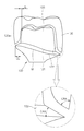
도 5는 크라운의 하단과 마진 라인의 편차가 발생한 경우 갭 조절 돌기를 이용한 조절을 나타낸 것이다.FIG. 5 shows the adjustment using a gap adjusting projection when a deviation between a lower end of the crown and a margin line occurs.
좌측에 도시한 바와 같이, 크라운의 하단(실선)과 상부지대주의 하단인 마진(점선)이 위치 편차를 가지는 경우, 적절한 위치에 갭 조절 돌기를 부가하거나 삭제하여 우측에 도시한 바와 같이 위치 편차를 조절할 수 있다.
As shown in the left side, when the lower end (solid line) of the crown and the margin (dotted line) at the lower end of the upper region have a positional deviation, a gap adjusting projection is added or deleted at a proper position, Can be adjusted.
이상 살펴본 바와 같이, 본 발명은 픽스처와, 지대주와 크라운을 포함하는 치과용 임플란트 보철물의 지대주와 크라운을 결합시키는 방법으로, 상기 지대주는 크라운과 접촉라인인 마진 위쪽의 상부지대주와, 상기 마진 아래쪽의 하부지대주를 포함하며, 상기 상부지대주는 상기 마진으로부터 일정 범위의 폭과 각도를 가지는 챔퍼면과, 상기 챔퍼면에서 원추형으로 돌출된 형태의 테이퍼를 구비하며, 상기 테이퍼의 측면에는 상기 크라운의 내면과 접촉하는 갭 조절 돌기를 구비하는 지대주와, 크라운의 결합방법에 있어서, 상기 갭 조절 돌기를 부가 또는 삭제하며, 상기 지대주와 상기 크라운 사이의 간격을 조절한 후 상기 지대주와 상기 크라운을 접착하도록 함으로써, 지대주와 크라운이 일정 수준의 간격을 유지한 상태로 결합할 수 있도록 한 것이다.
As described above, according to the present invention, there is provided a method of joining an abutment and a crown of a dental implant prosthesis including a fixture and an abutment and a crown, wherein the abutment is in contact with an upper abutment above the margin in contact with the crown, Wherein the upper surface of the taper has a chamfer surface having a width and an angle of a certain range from the margin and a taper protruding from the chamfer surface in a conical shape, The abutment and the crown may be attached or detached by adjusting the distance between the abutment and the crown and then the abutment and the crown are bonded to each other, Abutments and crowns can be combined with a certain level of spacing The.
110 : 픽스처
120 : 지대주
120a : 상부지대주
120b : 하부지대주
M : 마진
130 : 크라운
127 : 갭 조절 돌기
127a : 돌기홈110: Fixtures
120: abutment
120a: Upper abutment
120b:
M: Margin
130: Crown
127: gap regulating projection
127a: projection groove
Claims (7)
상기 지대주는 크라운과 접촉라인인 마진 위쪽의 상부지대주와, 상기 마진 아래쪽의 하부지대주를 포함하며,
상기 상부지대주는 상기 마진으로부터 일정 범위의 폭과 각도를 가지는 챔퍼면과, 상기 챔퍼면에서 원추형으로 돌출된 형태의 테이퍼를 구비하며,
상기 테이퍼의 측면에는 상기 크라운의 내면과 접촉하는 갭 조절 돌기를 구비하는 것을 특징으로 하는 지대주와 크라운 결합 구조.
The fixture and abutment of the dental implant prosthesis including abutment and crown,
Wherein the abutment has an upper abutment on the upper side of the margin which is a contact line with the crown and a lower abutment on the lower side of the margin,
Wherein the upper abutment has a chamfered surface having a width and an angle of a certain range from the margin and a taper protruding from the chamfered surface,
Wherein the side surface of the taper has a gap adjusting protrusion that contacts the inner surface of the crown.
상기 테이퍼의 측면과 상기 크라운의 내면은 0.02~0.1mm 범위의 간격을 유지하는 것을 특징으로 하는 지대주와 크라운 결합 구조.
The method according to claim 1,
Wherein the side surface of the taper and the inner surface of the crown are spaced from 0.02 to 0.1 mm.
상기 갭 조절 돌기는 상기 테이퍼의 측면에서 일체로 돌출 형성되는 것을 특징으로 하는 지대주와 크라운 결합 구조.
The method according to claim 1,
Wherein the gap regulating protrusion is integrally protruded from a side surface of the taper.
상기 갭 조절 돌기는
상기 테이퍼의 측면에 형성된 돌기홈에 부착 형성되는 것을 특징으로 하는 지대주와 크라운 결합 구조.
The method according to claim 1,
The gap regulating projection
Wherein the abutment member and the crown coupling structure are attached to the projection groove formed on the side surface of the taper.
상기 갭 조절 돌기는 복수개가 방사상으로 형성되는 것을 특징으로 하는 지대주와 크라운 결합 구조.
The method according to claim 1,
And a plurality of gap regulating protrusions are formed radially.
상기 지대주는 크라운과 접촉라인인 마진 위쪽의 상부지대주와, 상기 마진 아래쪽의 하부지대주를 포함하며, 상기 상부지대주는 상기 마진으로부터 일정 범위의 폭과 각도를 가지는 챔퍼면과, 상기 챔퍼면에서 원추형으로 돌출된 형태의 테이퍼를 구비하며, 상기 테이퍼의 측면에는 상기 크라운의 내면과 접촉하는 갭 조절 돌기를 구비하는 지대주와, 크라운의 결합방법에 있어서,
상기 갭 조절 돌기를 부가 또는 삭제하며, 상기 지대주와 상기 크라운 사이의 간격을 조절한 후 상기 지대주와 상기 크라운을 접착하는 것을 특징으로 하는 지대주와 크라운 결합방법.
A method of combining an abutment and a crown of a dental implant prosthesis including a fixture and an abutment and a crown,
Wherein the abutment includes a top abutment above the margin that is a line of contact with the crown and a bottom abutment below the margin, wherein the abutment has a chamfer surface having a width and angle from the margin, Wherein the taper has a protruding shape and the side surface of the taper has a gap adjusting protrusion contacting the inner surface of the crown,
Wherein the abutment and the crown are attached to each other by adding or removing the gap adjusting protrusion and adjusting the distance between the abutment and the crown.
상기 테이퍼의 측면과 상기 크라운의 내면은 0.02~0.1mm 의 간격을 형성하도록 하는 것을 특징으로 하는 지대주와 크라운 결합방법.The method according to claim 6,
Wherein the side surface of the taper and the inner surface of the crown form an interval of 0.02 to 0.1 mm.
Priority Applications (1)
| Application Number | Priority Date | Filing Date | Title |
|---|---|---|---|
| KR1020120146253A KR101435544B1 (en) | 2012-12-14 | 2012-12-14 | Crown mounting structure and mounting method of dental implant |
Applications Claiming Priority (1)
| Application Number | Priority Date | Filing Date | Title |
|---|---|---|---|
| KR1020120146253A KR101435544B1 (en) | 2012-12-14 | 2012-12-14 | Crown mounting structure and mounting method of dental implant |
Publications (2)
| Publication Number | Publication Date |
|---|---|
| KR20140077436A true KR20140077436A (en) | 2014-06-24 |
| KR101435544B1 KR101435544B1 (en) | 2014-09-02 |
Family
ID=51129372
Family Applications (1)
| Application Number | Title | Priority Date | Filing Date |
|---|---|---|---|
| KR1020120146253A Active KR101435544B1 (en) | 2012-12-14 | 2012-12-14 | Crown mounting structure and mounting method of dental implant |
Country Status (1)
| Country | Link |
|---|---|
| KR (1) | KR101435544B1 (en) |
Cited By (1)
| Publication number | Priority date | Publication date | Assignee | Title |
|---|---|---|---|---|
| WO2018064022A1 (en) * | 2016-09-27 | 2018-04-05 | Dentsply Sirona Inc. | Dental prosthetic system with dry-fit capability |
Families Citing this family (3)
| Publication number | Priority date | Publication date | Assignee | Title |
|---|---|---|---|---|
| KR102097376B1 (en) | 2019-10-18 | 2020-04-06 | 채희진 | Implants that can distribute the force of the implants and are easy to detachable |
| KR102464101B1 (en) | 2020-11-13 | 2022-11-04 | 채희진 | multiple piece type implant prosthesis |
| KR102658870B1 (en) * | 2023-07-26 | 2024-04-19 | 이노덴 주식회사 | Dental abutment with a triple structure and dental implant system having the same |
Family Cites Families (4)
| Publication number | Priority date | Publication date | Assignee | Title |
|---|---|---|---|---|
| WO1999029255A1 (en) | 1997-12-10 | 1999-06-17 | Diro, Inc. | Dental implant system and method |
| SE534830C2 (en) | 2004-01-29 | 2012-01-10 | Nobel Biocare Services Ag | Dental implant device |
| CN101677845B (en) * | 2007-05-16 | 2014-03-19 | 诺贝尔生物服务公司 | Ceramic one-piece dental implant |
| US8454363B2 (en) | 2008-11-06 | 2013-06-04 | William B. Worthington | Dental implant system |
-
2012
- 2012-12-14 KR KR1020120146253A patent/KR101435544B1/en active Active
Cited By (1)
| Publication number | Priority date | Publication date | Assignee | Title |
|---|---|---|---|---|
| WO2018064022A1 (en) * | 2016-09-27 | 2018-04-05 | Dentsply Sirona Inc. | Dental prosthetic system with dry-fit capability |
Also Published As
| Publication number | Publication date |
|---|---|
| KR101435544B1 (en) | 2014-09-02 |
Similar Documents
| Publication | Publication Date | Title |
|---|---|---|
| KR101881421B1 (en) | Abutment assembly | |
| KR101943437B1 (en) | Abutment assembly and Method for assembling the same | |
| KR101966407B1 (en) | Abutment assembly | |
| US9675434B2 (en) | Dental bridge | |
| US20150044635A1 (en) | Abutment capable of accommodating core crowns manufactured at various angles and functioning as a healing abutment having a cap attached thereto, method for manufacturing dental implant prostheses using the abutment, and method for implant surgery using the abutment | |
| KR100407796B1 (en) | Prosthetic dentistry for false teeth that is made from pin retented inlay bridge | |
| KR20150010118A (en) | Manufacturing method of customized dental implant using computer aided design and computer aided manufactuirng | |
| KR101524192B1 (en) | Cervical Shape Abutment for Dental Implant | |
| US10806548B2 (en) | Methods and devices for countering gingival effects in dental restoration | |
| AU2002236309A1 (en) | Pin-retained inlay bridge and process of making and fitting such | |
| KR20150010119A (en) | Manufacturing method of semi-customized dental implant using computer aided design and computer aided manufacturing | |
| KR101435544B1 (en) | Crown mounting structure and mounting method of dental implant | |
| KR20140118136A (en) | Titanium multiple abutment for dental implant | |
| US10682208B2 (en) | Abutment assembly and manufacturing method thereof | |
| KR101265969B1 (en) | Manufacturing method of customized abutment for implant having enhanced adatation | |
| KR20170139414A (en) | Medical implant | |
| KR20160095260A (en) | Dental implant having enhanced adaptation | |
| KR20240179022A (en) | Multi-unit dental implant | |
| US20230053661A1 (en) | Dental restoration system and method of building a restoration | |
| KR101124004B1 (en) | Prosthesis structure for bridge implant | |
| KR101406047B1 (en) | Manufacturing method of customized dental implant | |
| KR200242258Y1 (en) | Pin retented inlay bridge | |
| KR20210071682A (en) | Abutment assembly and method for assembling the same | |
| RU198695U1 (en) | ABUTMENT | |
| EP4018964A1 (en) | One-piece tissue level ceramic dental implant with a dual internal and external connection for a custom-made dental restoration |
Legal Events
| Date | Code | Title | Description |
|---|---|---|---|
| A201 | Request for examination | ||
| PA0109 | Patent application |
St.27 status event code: A-0-1-A10-A12-nap-PA0109 |
|
| PA0201 | Request for examination |
St.27 status event code: A-1-2-D10-D11-exm-PA0201 |
|
| D13-X000 | Search requested |
St.27 status event code: A-1-2-D10-D13-srh-X000 |
|
| D14-X000 | Search report completed |
St.27 status event code: A-1-2-D10-D14-srh-X000 |
|
| E902 | Notification of reason for refusal | ||
| PE0902 | Notice of grounds for rejection |
St.27 status event code: A-1-2-D10-D21-exm-PE0902 |
|
| E13-X000 | Pre-grant limitation requested |
St.27 status event code: A-2-3-E10-E13-lim-X000 |
|
| P11-X000 | Amendment of application requested |
St.27 status event code: A-2-2-P10-P11-nap-X000 |
|
| P13-X000 | Application amended |
St.27 status event code: A-2-2-P10-P13-nap-X000 |
|
| PG1501 | Laying open of application |
St.27 status event code: A-1-1-Q10-Q12-nap-PG1501 |
|
| E701 | Decision to grant or registration of patent right | ||
| PE0701 | Decision of registration |
St.27 status event code: A-1-2-D10-D22-exm-PE0701 |
|
| GRNT | Written decision to grant | ||
| PR0701 | Registration of establishment |
St.27 status event code: A-2-4-F10-F11-exm-PR0701 |
|
| PR1002 | Payment of registration fee |
St.27 status event code: A-2-2-U10-U11-oth-PR1002 Fee payment year number: 1 |
|
| PG1601 | Publication of registration |
St.27 status event code: A-4-4-Q10-Q13-nap-PG1601 |
|
| PN2301 | Change of applicant |
St.27 status event code: A-5-5-R10-R11-asn-PN2301 |
|
| R18-X000 | Changes to party contact information recorded |
St.27 status event code: A-5-5-R10-R18-oth-X000 |
|
| PN2301 | Change of applicant |
St.27 status event code: A-5-5-R10-R14-asn-PN2301 |
|
| P22-X000 | Classification modified |
St.27 status event code: A-4-4-P10-P22-nap-X000 |
|
| FPAY | Annual fee payment |
Payment date: 20170822 Year of fee payment: 4 |
|
| PR1001 | Payment of annual fee |
St.27 status event code: A-4-4-U10-U11-oth-PR1001 Fee payment year number: 4 |
|
| PN2301 | Change of applicant |
St.27 status event code: A-5-5-R10-R11-asn-PN2301 |
|
| PN2301 | Change of applicant |
St.27 status event code: A-5-5-R10-R14-asn-PN2301 |
|
| FPAY | Annual fee payment |
Payment date: 20180704 Year of fee payment: 5 |
|
| PR1001 | Payment of annual fee |
St.27 status event code: A-4-4-U10-U11-oth-PR1001 Fee payment year number: 5 |
|
| P14-X000 | Amendment of ip right document requested |
St.27 status event code: A-5-5-P10-P14-nap-X000 |
|
| P22-X000 | Classification modified |
St.27 status event code: A-4-4-P10-P22-nap-X000 |
|
| P22-X000 | Classification modified |
St.27 status event code: A-4-4-P10-P22-nap-X000 |
|
| FPAY | Annual fee payment |
Payment date: 20190812 Year of fee payment: 6 |
|
| PR1001 | Payment of annual fee |
St.27 status event code: A-4-4-U10-U11-oth-PR1001 Fee payment year number: 6 |
|
| FPAY | Annual fee payment |
Payment date: 20200814 Year of fee payment: 7 |
|
| PR1001 | Payment of annual fee |
St.27 status event code: A-4-4-U10-U11-oth-PR1001 Fee payment year number: 7 |
|
| FPAY | Annual fee payment |
Payment date: 20210816 Year of fee payment: 8 |
|
| PR1001 | Payment of annual fee |
St.27 status event code: A-4-4-U10-U11-oth-PR1001 Fee payment year number: 8 |
|
| FPAY | Annual fee payment |
Payment date: 20220708 Year of fee payment: 9 |
|
| PR1001 | Payment of annual fee |
St.27 status event code: A-4-4-U10-U11-oth-PR1001 Fee payment year number: 9 |
|
| PR1001 | Payment of annual fee |
St.27 status event code: A-4-4-U10-U11-oth-PR1001 Fee payment year number: 10 |
|
| PR1001 | Payment of annual fee |
St.27 status event code: A-4-4-U10-U11-oth-PR1001 Fee payment year number: 11 |
|
| R18-X000 | Changes to party contact information recorded |
St.27 status event code: A-5-5-R10-R18-oth-X000 |
|
| PR1001 | Payment of annual fee |
St.27 status event code: A-4-4-U10-U11-oth-PR1001 Fee payment year number: 12 |
|
| U11 | Full renewal or maintenance fee paid |
Free format text: ST27 STATUS EVENT CODE: A-4-4-U10-U11-OTH-PR1001 (AS PROVIDED BY THE NATIONAL OFFICE) Year of fee payment: 12 |
|
| P14 | Amendment of ip right document requested |
Free format text: ST27 STATUS EVENT CODE: A-5-5-P10-P14-NAP-X000 (AS PROVIDED BY THE NATIONAL OFFICE) |
|
| P14-X000 | Amendment of ip right document requested |
St.27 status event code: A-5-5-P10-P14-nap-X000 |