KR20140077607A - Optical finger mouse - Google Patents
Optical finger mouse Download PDFInfo
- Publication number
- KR20140077607A KR20140077607A KR1020120146601A KR20120146601A KR20140077607A KR 20140077607 A KR20140077607 A KR 20140077607A KR 1020120146601 A KR1020120146601 A KR 1020120146601A KR 20120146601 A KR20120146601 A KR 20120146601A KR 20140077607 A KR20140077607 A KR 20140077607A
- Authority
- KR
- South Korea
- Prior art keywords
- substrate
- input device
- disposed
- input
- switch
- Prior art date
- Legal status (The legal status is an assumption and is not a legal conclusion. Google has not performed a legal analysis and makes no representation as to the accuracy of the status listed.)
- Withdrawn
Links
Images


Classifications
-
- G—PHYSICS
- G06—COMPUTING OR CALCULATING; COUNTING
- G06F—ELECTRIC DIGITAL DATA PROCESSING
- G06F3/00—Input arrangements for transferring data to be processed into a form capable of being handled by the computer; Output arrangements for transferring data from processing unit to output unit, e.g. interface arrangements
- G06F3/01—Input arrangements or combined input and output arrangements for interaction between user and computer
- G06F3/03—Arrangements for converting the position or the displacement of a member into a coded form
- G06F3/033—Pointing devices displaced or positioned by the user, e.g. mice, trackballs, pens or joysticks; Accessories therefor
- G06F3/0354—Pointing devices displaced or positioned by the user, e.g. mice, trackballs, pens or joysticks; Accessories therefor with detection of two-dimensional [2D] relative movements between the device, or an operating part thereof, and a plane or surface, e.g. 2D mice, trackballs, pens or pucks
- G06F3/03543—Mice or pucks
-
- G—PHYSICS
- G06—COMPUTING OR CALCULATING; COUNTING
- G06F—ELECTRIC DIGITAL DATA PROCESSING
- G06F3/00—Input arrangements for transferring data to be processed into a form capable of being handled by the computer; Output arrangements for transferring data from processing unit to output unit, e.g. interface arrangements
- G06F3/01—Input arrangements or combined input and output arrangements for interaction between user and computer
- G06F3/03—Arrangements for converting the position or the displacement of a member into a coded form
- G06F3/041—Digitisers, e.g. for touch screens or touch pads, characterised by the transducing means
- G06F3/042—Digitisers, e.g. for touch screens or touch pads, characterised by the transducing means by opto-electronic means
Landscapes
- Engineering & Computer Science (AREA)
- General Engineering & Computer Science (AREA)
- Theoretical Computer Science (AREA)
- Human Computer Interaction (AREA)
- Physics & Mathematics (AREA)
- General Physics & Mathematics (AREA)
- Position Input By Displaying (AREA)
Abstract
옵티컬 핑거 마우스가 제공된다. 옵티컬 핑거 마우스는 제1 기판, 제1 입력 및 제2 입력을 입력받는 제1 입력 장치 및 상기 제1 기판 상면에 배치되고, 상기 목적 물체의 클릭에 반응하는 스위치를 포함하되, 상기 제1 입력 장치는, 상기 스위치 상부에 배치되고, 광원과 이미지센서가 실장된 제2 기판과, 상기 제2 기판 상부에 배치되고, 상기 광원으로부터 출사되어 목적 물체에 반사된 반사광을 투과시키는 광투과부와, 상기 제2 기판 상부에 배치되고, 상기 반사광의 광경로를 조절하는 렌즈와, 상기 제2 기판 상부에 배치되고, 상기 목적 물체가 접촉되는 커버부를 포함한다.An optical finger mouse is provided. An optical finger mouse includes a first substrate, a first input device receiving a first input and a second input, and a switch disposed on an upper surface of the first substrate and responsive to a click of the object, A second substrate disposed above the switch and having a light source and an image sensor mounted thereon, a light transmitting portion disposed on the second substrate, transmitting the reflected light reflected from the object and emitted from the light source, 2 a lens disposed on the substrate for adjusting an optical path of the reflected light, and a cover disposed on the second substrate and contacting the object.
Description
본 발명은 옵티컬 핑거 마우스에 관한 것이다.The present invention relates to an optical finger mouse.
컴퓨터 과학 분야가 발달함에 따라, 사용자가 컴퓨터 장치에 정보를 입력할 수 있는 다양한 장치가 개발되고 있다. 예를 들어, 사용자는 포인팅 장치를 조작하면, 포인팅 장치의 이동에 대응하는 위치 데이터가 생성된다. 그리고, 이러한 위치 데이터는 디스플레이 상에 나타나는 포인터 이미지의 움직임으로 변환된다.As the field of computer science progresses, various devices are being developed that allow users to input information into computer devices. For example, when the user operates the pointing device, position data corresponding to the movement of the pointing device is generated. This position data is then converted into the motion of the pointer image appearing on the display.
따라서, 포인팅 장치를 움직임으로써, 사용자는 포인터 이미지를 디스플레이 상에 표시되는 오브젝트와 연관시킬 수 있다. 여기서, 오브젝트란 메뉴, 버튼, 이미지 등 선택되었을 때 특정 동작이 수행되도록 하는 사용자 인터페이스를 의미한다. 그 후, 사용자는 포인팅 장치의 특정 버튼을 누르는 것과 같은 선택 동작을 통하여 해당 오브젝트와 관련된 특정 명령을 수행할 수 있게 된다.Thus, by moving the pointing device, the user can associate the pointer image with the displayed object on the display. Here, an object refers to a user interface that allows a specific operation to be performed when a menu, button, image, or the like is selected. Thereafter, the user can perform a specific command related to the object through a selection operation such as pressing a specific button of the pointing device.
한편, 개인용 컴퓨터의 운영체제(OS, Operating System)는, 예를 들어, 윈도우(Windows), 안드로이드(Android) 등이 사용되고 있다. 사용자는 특정 명령을 입력할 때, 마우스(mouse)와 같은 포인팅 장치의 드래그, 스크롤, 클릭 등을 통해 명령을 입력할 수 있다.On the other hand, for example, Windows (Windows), Android (Android), and the like are used as an operating system (OS) of a personal computer. When a user inputs a specific command, the user can input commands by dragging, scrolling, clicking, and the like of a pointing device such as a mouse.
본 발명이 해결하려는 과제는, 비용을 줄이고 공간적 제약을 최소화한 옵티컬 핑거 마우스 및 마이크로 터치패드 장치를 제공하는 것이다. SUMMARY OF THE INVENTION An object of the present invention is to provide an optical finger mouse and a micro touch pad device which reduce costs and minimize spatial restrictions.
본 발명이 해결하려는 과제들은 이상에서 언급한 과제들로 제한되지 않으며, 언급되지 않은 또 다른 과제들은 아래의 기재로부터 당업자에게 명확하게 이해될 수 있을 것이다.The problems to be solved by the present invention are not limited to the above-mentioned problems, and other matters not mentioned can be clearly understood by those skilled in the art from the following description.
상기 기술적 과제를 달성하기 위한 본 발명의 일 실시예에 따른 옵티컬 핑거 마우스는, 제1 기판, 제1 입력 및 제2 입력을 입력받는 제1 입력 장치 및 상기 제1 기판 상면에 배치되고, 상기 목적 물체의 클릭에 반응하는 스위치를 포함하되, 상기 제1 입력 장치는, 상기 스위치 상부에 배치되고, 광원과 이미지센서가 실장된 제2 기판과, 상기 제2 기판 상부에 배치되고, 상기 광원으로부터 출사되어 목적 물체에 반사된 반사광을 투과시키는 광투과부와, 상기 제2 기판 상부에 배치되고, 상기 반사광의 광경로를 조절하는 렌즈와, 상기 제2 기판 상부에 배치되고, 상기 목적 물체가 접촉되는 커버부를 포함한다.According to an aspect of the present invention, there is provided an optical finger mouse including a first substrate, a first input device receiving a first input and a second input, and a second input device disposed on an upper surface of the first substrate, And a switch for responding to a click of an object, wherein the first input device comprises: a second substrate disposed above the switch, the second substrate having a light source and an image sensor mounted thereon; A lens disposed on the second substrate and adapted to adjust an optical path of the reflected light; a second lens disposed on the second substrate, .
상기 다른 기술적 과제를 달성하기 위한 본 발명의 다른 실시예에 따른 옵티컬 핑거 마우스는, 광원과 이미지센서가 실장된 제2 기판, 상기 제2 기판 상부에 배치되고, 상기 광원으로부터 출사되어 목적 물체에 반사된 반사광을 투과시키는 광투과부, 상기 제2 기판 상부에 배치되고, 상기 반사광의 광경로를 조절하는 렌즈, 상기 제2 기판 상부에 배치되고, 상기 목적 물체가 접촉되는 커버부 및 상기 제2 기판 하부에 배치되고, 상기 목적 물체의 클릭에 반응하는 돔 키를 포함한다. According to another aspect of the present invention, there is provided an optical finger mouse including: a second substrate having a light source and an image sensor mounted thereon; a second substrate disposed on the second substrate; A lens disposed on the second substrate and adapted to adjust an optical path of the reflected light, a cover portion disposed on the second substrate, the cover portion contacting the object, and a light- And a dome key that is responsive to a click of the object.
상기 다른 기술적 과제를 달성하기 위한 본 발명의 또다른 실시예에 따른 옵티컬 핑거 마우스는, 목적 물체의 클릭에 반응하는 돔 키 및 상기 목적 물체에 반사된 광을 입력받고, 상기 돔 키 상부에 배치되는 제1 입력장치를 포함하되, 상기 제1 입력장치는, 광원과 이미지센서가 실장된 제2 기판과, 상기 제2 기판 상부에 배치되고, 상기 광원으로부터 출사되어 목적 물체에 반사된 반사광을 투과시키는 광투과부와, 상기 제2 기판 상부에 배치되고, 상기 반사광의 광경로를 조절하는 렌즈와, 상기 제2 기판 상부에 배치되고, 상기 목적 물체가 접촉되는 커버부를 포함한다.According to another aspect of the present invention, there is provided an optical finger mouse for receiving a dome key responsive to a click of a target object and a light reflected from the target object, The first input device includes a second substrate on which a light source and an image sensor are mounted, and a second substrate on the second substrate. The first input device includes a first substrate on which a light source and an image sensor are mounted, And a cover disposed on the second substrate and in contact with the object. The cover includes a light transmitting portion, a lens disposed on the second substrate, a lens for adjusting an optical path of the reflected light, and a cover portion disposed on the second substrate.
상기한 바와 같이 본 발명에 따르면, 비용을 줄이고 공간적 제약을 최소화한 옵티컬 핑거 마우스 및 마이크로 터치패드 장치를 제공할 수 있다.As described above, according to the present invention, it is possible to provide an optical finger mouse and a micro touch pad device which can reduce cost and minimize spatial limitation.
본 발명의 효과들은 이상에서 언급한 효과들로 제한되지 않으며, 언급되지 않은 또 다른 효과들은 청구범위의 기재로부터 당업자에게 명확하게 이해될 수 있을 것이다.The effects of the present invention are not limited to the effects mentioned above, and other effects not mentioned can be clearly understood by those skilled in the art from the description of the claims.
도 1은 본 발명의 일 실시예에 따른 옵티컬 핑거 마우스의 단면도이다.
도 2는 본 발명의 일 실시예에 따른 제1 입력장치의 분해사시도이다.
도 3은 도 2의 제1 입력장치의 단면도이다.
도 4는 본 발명의 다른 실시예에 따른 제1 입력장치의 분해사시도이다.
도 5는 도 4의 제1 입력장치의 단면도이다.
도 6은 스위치의 단면도이다.
도 7은 도 1의 옵티컬 핑거 마우스 작동을 설명하기 위한 단면도이다.
도 8은 본 발명의 다른 실시예에 따른 옵티컬 핑거 마우스의 단면도이다.
도 9는 도 8의 옵티컬 핑거 마우스 작동을 설명하기 위한 단면도이다.
도 10은 본 발명의 일 실시예에 따른 전자기기의 블록 개념도이다.
도 11은 옵티컬 핑거 마우스가 사용되는 실시예이다.1 is a cross-sectional view of an optical finger mouse according to an embodiment of the present invention.
2 is an exploded perspective view of a first input device according to an embodiment of the present invention.
3 is a cross-sectional view of the first input device of Fig.
4 is an exploded perspective view of a first input device according to another embodiment of the present invention.
5 is a cross-sectional view of the first input device of Fig.
6 is a cross-sectional view of the switch.
7 is a cross-sectional view illustrating the operation of the optical finger mouse of FIG.
8 is a cross-sectional view of an optical finger mouse according to another embodiment of the present invention.
FIG. 9 is a cross-sectional view illustrating the operation of the optical finger mouse of FIG. 8. FIG.
10 is a conceptual block diagram of an electronic apparatus according to an embodiment of the present invention.
11 is an embodiment in which an optical finger mouse is used.
본 발명의 이점 및 특징, 그리고 그것들을 달성하는 방법은 첨부되는 도면과 함께 상세하게 후술되어 있는 실시예들을 참조하면 명확해질 것이다. 그러나 본 발명은 이하에서 개시되는 실시예들에 한정되는 것이 아니라 서로 다른 다양한 형태로 구현될 것이며, 단지 본 실시예들은 본 발명의 개시가 완전하도록 하며, 본 발명이 속하는 기술분야에서 통상의 지식을 가진 자에게 발명의 범주를 완전하게 알려주기 위해 제공되는 것이며, 본 발명은 청구항의 범주에 의해 정의될 뿐이다. 명세서 전체에 걸쳐 동일 참조 부호는 동일 구성 요소를 지칭한다.BRIEF DESCRIPTION OF THE DRAWINGS The advantages and features of the present invention and the manner of achieving them will become apparent with reference to the embodiments described in detail below with reference to the accompanying drawings. The present invention may, however, be embodied in many different forms and should not be construed as being limited to the embodiments set forth herein. Rather, these embodiments are provided so that this disclosure will be thorough and complete, and will fully convey the scope of the invention to those skilled in the art. Is provided to fully convey the scope of the invention to those skilled in the art, and the invention is only defined by the scope of the claims. Like reference numerals refer to like elements throughout the specification.
하나의 소자(elements)가 다른 소자와 "접속된(connected to)" 또는 "커플링된(coupled to)" 이라고 지칭되는 것은, 다른 소자와 직접 연결 또는 커플링된 경우 또는 중간에 다른 소자를 개재한 경우를 모두 포함한다. 반면, 하나의 소자가 다른 소자와 "직접 접속된(directly connected to)" 또는 "직접 커플링된(directly coupled to)"으로 지칭되는 것은 중간에 다른 소자를 개재하지 않은 것을 나타낸다. 명세서 전체에 걸쳐 동일 참조 부호는 동일 구성 요소를 지칭한다. "및/또는"은 언급된 아이템들의 각각 및 하나 이상의 모든 조합을 포함한다. One element is referred to as being "connected to " or" coupled to "another element, either directly connected or coupled to another element, One case. On the other hand, when one element is referred to as being "directly connected to" or "directly coupled to " another element, it does not intervene another element in the middle. Like reference numerals refer to like elements throughout the specification. "And / or" include each and every combination of one or more of the mentioned items.
비록 제1, 제2 등이 다양한 소자, 구성요소 및/또는 섹션들을 서술하기 위해서 사용되나, 이들 소자, 구성요소 및/또는 섹션들은 이들 용어에 의해 제한되지 않음은 물론이다. 이들 용어들은 단지 하나의 소자, 구성요소 또는 섹션들을 다른 소자, 구성요소 또는 섹션들과 구별하기 위하여 사용하는 것이다. 따라서, 이하에서 언급되는 제1 소자, 제1 구성요소 또는 제1 섹션은 본 발명의 기술적 사상 내에서 제2 소자, 제2 구성요소 또는 제2 섹션일 수도 있음은 물론이다.Although the first, second, etc. are used to describe various elements, components and / or sections, it is needless to say that these elements, components and / or sections are not limited by these terms. These terms are only used to distinguish one element, element or section from another element, element or section. Therefore, it goes without saying that the first element, the first element or the first section mentioned below may be the second element, the second element or the second section within the technical spirit of the present invention.
본 명세서에서 사용된 용어는 실시예들을 설명하기 위한 것이며 본 발명을 제한하고자 하는 것은 아니다. 본 명세서에서, 단수형은 문구에서 특별히 언급하지 않는 한 복수형도 포함한다. 명세서에서 사용되는 "포함한다(comprises)" 및/또는 "포함하는(comprising)"은 언급된 구성요소, 단계, 동작 및/또는 소자는 하나 이상의 다른 구성요소, 단계, 동작 및/또는 소자의 존재 또는 추가를 배제하지 않는다.The terminology used herein is for the purpose of illustrating embodiments and is not intended to be limiting of the present invention. In the present specification, the singular form includes plural forms unless otherwise specified in the specification. It is noted that the terms "comprises" and / or "comprising" used in the specification are intended to be inclusive in a manner similar to the components, steps, operations, and / Or additions.
다른 정의가 없다면, 본 명세서에서 사용되는 모든 용어(기술 및 과학적 용어를 포함)는 본 발명이 속하는 기술분야에서 통상의 지식을 가진 자에게 공통적으로 이해될 수 있는 의미로 사용될 수 있을 것이다. 또 일반적으로 사용되는 사전에 정의되어 있는 용어들은 명백하게 특별히 정의되어 있지 않는 한 이상적으로 또는 과도하게 해석되지 않는다. Unless defined otherwise, all terms (including technical and scientific terms) used herein may be used in a sense commonly understood by one of ordinary skill in the art to which this invention belongs. Also, commonly used predefined terms are not ideally or excessively interpreted unless explicitly defined otherwise.
이하 도 1 내지 도 7을 참조하여, 본 발명의 일 실시예에 따른 옵티컬 핑거 마우스(optical finger mouse)에 대해 설명한다.Hereinafter, an optical finger mouse according to an embodiment of the present invention will be described with reference to FIGS. 1 to 7. FIG.
도 1은 본 발명의 일 실시예에 따른 옵티컬 핑거 마우스의 단면도이고, 도 2는 본 발명의 일 실시예에 따른 제1 입력장치의 분해사시도이고, 도 3은 도 2의 제1 입력장치의 단면도이고, 도 4는 본 발명의 다른 실시예에 따른 제1 입력장치의 분해사시도이고, 도 5는 도 4의 제1 입력장치의 단면도이고, 도 6은 스위치의 단면도이며, 도 7은 도 1의 옵티컬 핑거 마우스 작동을 설명하기 위한 단면도이다.FIG. 1 is a cross-sectional view of an optical finger mouse according to an embodiment of the present invention, FIG. 2 is an exploded perspective view of a first input device according to an embodiment of the present invention, FIG. 3 is a cross- 4 is a cross-sectional view of the first input device of FIG. 4, FIG. 6 is a cross-sectional view of the switch, and FIG. 7 is a cross-sectional view of the first input device of FIG. Sectional view for explaining the operation of the optical finger mouse.
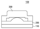
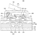
먼저, 도 1을 참조하면, 본 발명의 일 실시예에 따른 옵티컬 핑거 마우스(100)는 제1 기판(110), 스위치(200) 및 제1 입력장치(300)을 포함한다. 옵티컬 핑거 마우스(100)는 입력 장치의 일종이고, 예를 들어, 휴대폰, 스마트폰, PDA, 넷북, 노트북, 태블릿PC 등과 같은 다양한 전자기기에 탑재될 수 있다. 그러나 이에 한정되는 것은 아니다.Referring to FIG. 1, an
제1 기판(110)은 옵티컬 핑거 마우스(100) 하부에 배치될 수 있다. 제1 기판(110)은 PCB(printed circuit board)일 수 있으나 이에 제한되는 것은 아니다. The
계속해서, 스위치(200)는 제1 기판(110) 상면에 배치될 수 있으며 제1 입력장치(300)는 스위치(200) 상부에 위치할 수 있다. 즉, 스위치(200)는 제1 기판(110)과 제1 입력장치(300) 사이에 위치할 수 있으며, 적층된 구조를 가질 수 있다. 제1 입력장치(300)와 스위치(200)는 전기적으로 제1 기판(110)과 연결되어 신호를 전달할 수 있다. 제1 입력장치(300)와 스위치(200)의 형태 및 작용 등은 후술하기로 한다.Subsequently, the
최근에, 하나의 입력장치로 멀티 터치 제스처(multi-touch gesture) 기능을 제공하는 O/S가 개발되어 있다. O/S의 개발에 따라, 입력 장치도 복수개의 목적물체를 이용하여 멀티 터치 제스처 동작을 수행할 수 있도록 개발되었다. 멀티 터치 제스처는 예를 들어, 복수의 목적물체로 스크롤(scroll), 줌인(zoom in), 줌아웃(zoom out), 회전 등과 같은 동작을 수행하는 것을 의미할 수 있으나, 이에 한정되는 것은 아니다. 이러한 멀티 터치 제스처 동작을 수행할 수 있는 입력장치는 크기가 커서 휴대성이 요구되는, 예를 들어 소형화된 모바일 기기나 키보드 등에 탑재하기에는 공간적인 제약이 있을 수 있다. 따라서, 공간적인 제약을 개선하고 멀티 터치 제스처를 구현하기 위하여 제1 입력장치(300)와 스위치(200)를 하나의 옵티컬 핑거 마우스(100)에서 결합시킬 수 있다. 이 경우, 멀티 터치 제스처 동작을 실행하기 위하여 복수의 옵티컬 핑거 마우스(100)를 사용하거나 별도의 기능키를 추가할 필요가 없어 공간적, 경제적으로 유리하다. 또한, 목적물체 하나만이 필요하여 사용자에게도 편리하다.Recently, an O / S has been developed which provides a multi-touch gesture function with a single input device. According to O / S development, an input device has also been developed to perform multi-touch gesture operation using a plurality of object objects. The multi-touch gesture may mean, for example, performing operations such as scrolling, zooming in, zooming out, rotating, and the like to a plurality of object objects, but is not limited thereto. An input device capable of performing such a multi-touch gesture operation may be limited in space, for example, in a mobile device or a keyboard, which is required to have a large size and requires portability, for example, in a miniaturized mobile device or a keyboard. Therefore, the
도 2 및 도 3을 참조하여, 제1 입력장치(300)에 대하여 구체적으로 설명하기로 한다.Referring to FIGS. 2 and 3, the
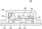
도 2 및 도 3을 참조하면, 제1 입력장치(300)는 제2 기판(310), 고정부(320), 렌즈(333), 프리즘(335) 및 덮개부(340)를 포함할 수 있다.2 and 3, the
제2 기판(310)은 예를 들어, PCB일 수 있다. 그리고 이러한 제2 기판(310) 상에는 도 2 및 도 3에 도시된 것과 같이 광원(315)과 광센서(313)가 실장될 수 있는데, 여기서 제1 입력장치(300)의 광원(315)은 적외선(IR) 광을 출사시키는 적외선 광원일 수 있다. 더욱 구체적으로, 광원(12)은 적외선 광을 출사시키는 적외선 LED 광원일 수 있다.The
고정부(320)는 렌즈(333) 및 광투과부(323) 간의 얼라인먼트(alignment)가 유지되도록 렌즈(333), 광투과부(323)를 고정하는 역할을 할 수 있으며, 제2 기판(310) 상부에 배치될 수 있다. 여기서, 렌즈(333)는 광원(315)으로부터 출사되어 목적 물체(미도시)에 반사된 반사광의 광경로를 조절하는 기능을 수행하고, 광투과부(323)는 이렇게 광경로가 조절된 반사광을 투과시키는 기능 수행할 수 있는데, 고정부(320)는 이러한 렌즈(333), 광투과부(323)가 올바르게 정렬되도록 고정함으로써, 그 하부에 배치된 광센서(313)가 렌즈(333), 광투과부(323)를 순차적으로 통과한 광을 신뢰성 있게 감지할 수 있도록 하는 역할을 할 수 있다.The fixing
이때, 고정부(320)가 렌즈(333), 광투과부(323) 간의 얼라인먼트가 유지되도록 렌즈(333), 광투과부(323)를 고정하는 것은 고정부(320)에 형성된 고정 돌기(325)에 의해 구현될 수 있다.The fixing of the
구체적으로, 렌즈(333)는 도 2 및 도 3에 도시된 것과 같이 고정부(320)에 형성된 고정 돌기(325)에 의해 고정되고, 광투과부(323)는 고정부(320)에 형성되어 렌즈(333)와 얼라인먼트가 유지되도록 배치될 수 있다.2 and 3, the
한편, 제1 입력장치(300)에서 광투과부(323)는 도 2 및 도 3에 도시된 것과 같이 고정부(320)에 형성될 수 있다. 따라서, 이는 광투과부(323)와 고정부(320)를 별도로 형성하는 경우에 비해, 제1 입력장치(300)의 크기를 소형화 시킬 수 있는 장점을 가질 수 있다.Meanwhile, in the
렌즈(333)는 고정부(320)에 형성된 광투과부(323) 상부에 배치되고, 앞서 설명한 바와 같이 광원(315)으로부터 출사되어 목적 물체(미도시)에 반사된 반사광의 광경로를 조절하는 기능을 수행할 수 있다. 한편, 프리즘(335)은 도 2 및 도 3에 도시된 것과 같이 광원(315) 상부에 배치될 수 있는데, 이러한 프리즘(335)은 광원(315)으로부터 출사된 광이 목적 물체(미도시)에 도달하도록 광경로를 형성하는 기능을 수행할 수 있다. 이를 위해, 프리즘(335)은 광을 집광하는 집광 렌즈와 집광된 광을 반사시키는 반사면, 그리고 반사된 광을 목적 물체(미도시)까지 전달하는 출사면으로 이루어질 수 있다. 한편, 제1 입력장치(300)에서 이러한 렌즈(3330)와 프리즘(335)은 도시된 것과 같이 일체로 형성될 수 있다.The
덮개부(340)는 기판(310) 상부에 배치될 수 있으며, 앞서 설명한 광원(315), 광센서(313), 고정부(320), 렌즈(333) 및 프리즘(335)을 덮도록 배치되어, 이들을 보호하는 기능을 수행할 수 있다. 일반적으로 목적 물체(미도시)는 이러한 덮개부(340) 상에 위치할 수 있다.The
도 4 및 도 5를 참조하여, 제1 입력장치(301)의 다른 실시예를 설명하기로 한다. 상술한 것과 중복되는 내용은 생략하기로 한다.4 and 5, another embodiment of the
제1 입력장치(301)는 전도성 패드(350)를 더 포함할 수 있다. 전도성 패드(350)는 도 4 및 도 5에 도시된 바와 같이, 덮개부(340)의 하부에 배치될 수 있다. 전도성 패드(350)는 제1 입력장치(301)에 정전용량 입력 방식을 적용할 때 필요할 수 있다. 정전용량 입력 방식이란 목적 물체(미도시)의 터치에 반응하는 입력 방식으로, 목적물체(미도시), 예를 들어 손가락, 가 제1 입력장치(301)에 근접하는 경우 정전용량 값이 변화하므로 이를 입력으로 인지하는 방식이다.The
다시 도 4를 참조하면, 전도성 패드(350)는 플레이트(353)와 보호부(355)를 포함할 수 있다. 플레이트(353)는 목적 물체의 터치를 감지하는 부분이다. 플레이트(353)는 SUS(Steel Use Statinless) 재질일 수 있으나 이에 한정되는 것은 아니다. 보호부(355)는 덮개부(340) 내부에 존재할 수 있으며, 플레이트(353)의 하면에 존재할 수 있다. 보호부(355)는 플레이트(353)로부터 고정부(320), 렌즈(333), 프리즘(335) 등을 보호하기 위해 필요할 수 있다.Referring again to FIG. 4, the
한편, 전도성 패드(350)는 덮개부(340)와 일체형일 수 있다. 전도성 패드(350)가 덮개부(340)와 일체형인 경우, 제1 입력장치(301)의 크기를 최소화할 수 있어, 소형화에 유리할 수 있다. 또한, 전도성 패드(350)는 뚫려있는 부분이 존재할 수 있다. 제1 입력장치(301)는 광원(315)으로부터 출사된 광이 목적 물체(미도시)에 반사되고 반사된 광을 광센서(313)가 감지할 수 있어야 한다. 따라서 광원(315)으로부터 출사된 광이 목적 물체(미도시)에 도달할 수 있도록 전도성 패드(350)는 도 4에 도시된 바와 같이 광이 지나가는 자리가 뚫려있을 수 있다. 플레이트(353)와 보호부(355) 모두에 뚫려있는 부분이 존재할 수 있다.Meanwhile, the
전도성 패드(350)는 터치센서(미도시)와 연결될 수 있다. 터치센서(미도시)는 제1 입력장치(301) 내부에 존재할 수도 있고, 외부에 존재할 수도 있으며, 광센서(313)와 일체형일 수도 있다. 광센서(313)와 터치센서(미도시)가 일체형인 경우, 터치센서(미도시)를 위한 별도의 공간이나 배선이 필요치 않아 소형화에 유리하고 경제적으로도 유리하다.The
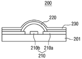
도 6을 참조하여 스위치(200)에 대하여 설명하기로 한다. 도 6에서는 스위치(200)가 돔 키인 경우를 도시하였으나, 이는 일 실시예일뿐이며 이에 제한되는 것은 아니다.The
스위치(200)는 제1 입력장치의 하부에 배치될 수 있다. 제1 입력장치가 빛 및/또는 목적 물체(미도시)의 움직임을 감지하는데 반해 스위치(200)는 목적 물체(미도시)의 클릭에 반응할 수 있으며, 예를 들어 멤브레인(membrane) 스위치, 폴리돔 스위치 또는 택트(tact) 스위치 등일 수 있다. 또한, 스위치(200)는 돔 키일 수 있다. 돔 키는 배선 위에 금속 도전성 돔을 올려 놓고, 사용자의 조작으로 금속 돔이 배선과 접촉함으로써 작동하는 스위치를 말한다. 스위치(200)가 돔 키이면 수명, 생산성, 클릭감, 크기 등에서 다른 스위치에 비하여 우수한 효과를 가질 수 있다.The
도 6을 참조하면, 스위치(200)는 제3 기판(201), 돔 스위치 배선(210), 돔 스위치(220) 및 투명 펫(pet) 필름(230)을 포함할 수 있다. 도 6에서의 제3 기판(201)은 옵티컬 핑거 마우스를 소형화하기 위하여, 도 1의 제1 기판(110)으로 대체할 수 있다. 제3 기판(201) 상에는 돔 스위치 배선(210)이 패터닝되어 있으며, 돔 스위치 배선(210)은 도전성 물질일 수 있다.Referring to FIG. 6, the
돔 스위치 배선(210) 상에는 돔 스위치(220)가 위치할 수 있다. 돔 스위치(220)는 제1 돔 스위치 배선(210a)과 접촉되어 있으며 돔 모양을 가질 수 있다. 돔 스위치(220)는 평소에는 신호 라인(210b)과 떨어져 있으나, 압력을 받으면 신호 라인(210b)과 접촉되어 입력 신호를 전달할 수 있다. 투명 펫 필름(230)은 돔 스위치(220)를 덮을 수 있고, 이에 따라 돔 스위치(220)를 보호할 수 있다.A
도 7을 참조하여, 옵티컬 핑거 마우스의 동작에 대하여 설명하기로 한다.The operation of the optical finger mouse will be described with reference to FIG.
본 발명의 일 실시예에 따른 옵티컬 핑거 마우스의 제1 입력 장치(300)는 광학식의 제1 입력을 받는다. 제1 입력 장치(300)의 덮개부(340) 상면에 목적 물체(미도시)를 올려놓고 덮개부(340) 상면의 수직 방향으로 목적 물체(미도시)를 움직이면 이를 제1 입력으로 인식한다. 구체적으로, 목적 물제(미도시)가 수직 방향으로 제1 입력 장치(300)의 덮개부(340)에 근접하거나 터치하면 광센서(313)는 목적 물체(미도시)의 수직 움직임을 감지하여 제1 입력으로 인식한다.The
또한, 제1 입력 장치(300)는 목적 물체(미도시)의 수평 방향의 움직임 즉, 스윕(sweep)에도 반응할 수 있다. 구체적으로, 목적 물체(미도시)를 제1 입력 장치(300)의 덮개부(340) 상면에 위치시키고, 덮개부(300)의 상면과 수평 방향으로 목적 물체(미도시)를 상하좌우로 스윕하면, 이를 제2 입력으로 인식하여 옵티컬 핑거 마우스와 연결된 장치(미도시)는 화면 또는 커서 등의 움직임으로 인식한다.In addition, the
도 7에는 도시되어 있지 않으나, 도 5와 같이 제1 입력장치(301)는 전도성 패드(350)를 포함할 수 있으며 이 경우에는 목적 물체(700)가 제1 입력장치(301)를 터치하는 경우에도 이를 제1 입력으로 감지할 수 있다. 즉, 전도성 패드(350)를 포함하는 제1 입력장치(301)는 목적 물체의 수직 방향의 움직임이 아니라, 제1 입력 장치(301)를 목적 물체(미도시)가 터치하면 이를 제1 입력으로 인식한다. 그러나, 목적 물체(미도시)의 수평 방향의 움직임에 대해서 반응하는 것은 전도성 패드(350)를 포함하지 않은 제1 입력장치(300)와 같다.Although not shown in FIG. 7, the
한편, 스위치(200)는 목적 물체(700)의 클릭에 반응할 수 있다. 목적 물체(700)가 덮개부(340)를 누르면 그에 따라 발생한 압력이 돔 스위치(220)에 전달되어 도 7에 도시된 바와 같이 돔 스위치(220)가 눌릴 수 있다. 결국, 돔 스위치(220)는 신호 라인(210b)에 접촉하여 입력을 전달하게 된다.On the other hand, the
이하에서는 옵티컬 핑거 마우스의 동작에 대해서 예를 들어서 설명하기로 한다. 상술한 바와 같이, 옵티컬 핑거 마우스는 2개의 입력, 즉, 스위치의 클릭과 제1 입력을 받을 수 있다. 하나의 옵티컬 핑거 마우스로 2개의 입력을 받을 수 있기 때문에 다양한 동작을 수행할 수 있다.Hereinafter, the operation of the optical finger mouse will be described by way of example. As described above, the optical finger mouse can receive two inputs, i.e., a switch click and a first input. One optical finger mouse can receive two inputs, so various operations can be performed.
예를 들어, 옵티컬 핑거 마우스를 기존의 컴퓨터 마우스와 동일하게 사용할 수 있다. 제1 입력을 컴퓨터 마우스의 좌측 버튼 입력으로, 스위치(200)의 클릭을 컴퓨터 마우스의 우측 버튼 입력으로 인식하도록 하여 기존의 컴퓨터 마우스와 동일하게 사용할 수 있다. 또는 이와 반대로, 제1 입력을 컴퓨터 마우스의 우측 버튼 입력으로, 스위치의 클릭을 컴퓨터 마우스의 좌측 버튼 입력으로 인식할 수도 있다.For example, an optical finger mouse can be used like an existing computer mouse. The first input is recognized as the left button input of the computer mouse and the click of the
다른 예로, 옵티컬 핑거 마우스로 복수개의 키 입력을 수행할 수 있다. 구체적으로, 제1 입력장치(300)의 덮개부(340)에 목적 물체(700)를 위치시키고 상하좌우로 스윕하면 옵티컬 핑거 마우스와 연결된 전자기기 화면의 커서는 목적 물체(700)의 움직임에 맞추어 이동한다. 스위치(200)를 1번 클릭하면 전자기기 화면의 아이콘을 선택하는 것으로, 스위치(200)를 2번 클릭하면 커서 위의 아이콘을 실행시키는 것으로, 스위치(200)를 길게 클릭하면 이전 단계로 이동하는 것으로 동작할 수 있다.As another example, a plurality of key inputs can be performed with an optical finger mouse. Specifically, when the
한편, 제1 입력이 한 번 있는 경우, 줌(zoom) 모드로 전환되며 목적 물체(700)를 제1 입력장치(300)의 덮개부(340)에서 스윕하면 스윕 방향에 따라 줌인(zoom in) 또는 줌아웃(zoom out)을 할 수 있다. 제1 입력이 두 번 있는 경우, 스크롤(scroll) 모드로 전환되며 목적 물체(700)를 제1 입력장치(300)의 덮개부(340)에서 스윕하면 전자기기 화면을 위 또는 아래로 스크롤할 수 있다.When the first input is once, the zoom mode is switched to, and the
옵티컬 핑거 마우스의 동작에 대하여 2가지의 경우를 예를 들어 상술하였으나 본 발명은 이에 제한되는 것은 아니며, 당해 기술 분야에서 통상의 지식을 가진 자라면, 본 발명의 옵티컬 핑거 마우스를 다양하게 사용할 수 있음을 이해할 수 있을 것이다.Although the optical finger mouse has been described in detail for two examples, the present invention is not limited thereto. Anyone skilled in the art can use the optical finger mouse of the present invention in various ways. .
도 8 및 도 9를 참조하여 본 발명의 다른 실시예예 따른 옵티컬 핑거 마우스를 설명하기로 한다. 상술한 것과 중복되는 내용은 생략하고 차이점 위주로 설명하기로 한다.8 and 9, an optical finger mouse according to another embodiment of the present invention will be described. The contents overlapping with those described above will be omitted and the differences will be mainly described.
도 8은 본 발명의 다른 실시예에 따른 옵티컬 핑거 마우스의 단면도이고, 도 9는 도 8의 옵티컬 핑거 마우스 작동을 설명하기 위한 단면도이다.FIG. 8 is a cross-sectional view of an optical finger mouse according to another embodiment of the present invention, and FIG. 9 is a cross-sectional view illustrating the operation of the optical finger mouse of FIG.
도 8 및 도 9를 참조하면 옵티컬 핑거 마우스(101)는 스위치(202)와 제1 입력장치(300)를 포함할 수 있다. 스위치(202)는 도 1과는 달리 뒤집어진 상태로 제1 입력장치(300)와 결합할 수 있으며, 제1 입력장치(300)는 스위치(202) 상에 위치할 수 있다. 도 8과 같이 제1 입력장치(300)와 스위치(202)가 배치되면, 제1 입력장치(300)의 제2 기판(310)(도 3 참조)과 스위치의 제3 기판(201)(도 6 참조)을 공유할 수 있으므로 도 1과 달리 제1 기판이 필요하지 않고 기판 하나만 사용할 수 있어 경제적, 공간적으로 유리할 수 있다. 하나의 기판만 사용하므로, 제2 기판(310) 하면에 돔 스위치 배선(210)이 형성될 수 있고, 돔 스위치(220)는 아래를 향해서 볼록한 형상을 가질 수 있다.Referring to FIGS. 8 and 9, the
도 9의 옵티컬 핑거 마우스(101)는 도 7의 옵티컬 핑거 마우스(300)와 동일하게 동작한다. 제1 입력장치(300)는 목적 물체(700)의 접근 및/또는 접촉을 입력으로 받으며, 스위치(202)는 목적 물체(700)의 클릭을 입력으로 받는다. 구체적으로, 목적 물체(700)가 옵티컬 핑거 마우스(301)를 클릭하면, 도 9에 도시된 바와 같이 돔 시트(220)는 압력을 받아 신호 라인(210b)에 접촉하여 입력을 전달하게 된다. 도 10 및 도 11을 참조하여, 본 발명의 실시예들에 따른 전자기기에 대해 설명하기로 한다.The
도 10은 본 발명의 실시예에 따른 전자기기의 블록 개념도이고, 도 11은 옵티컬 핑거 마우스가 사용되는 실시예이다.FIG. 10 is a block diagram of an electronic device according to an embodiment of the present invention, and FIG. 11 is an embodiment in which an optical finger mouse is used.
도 10을 참조하면, 본 발명의 일 실시예에 따른 전자기기는 본 발명의 실시예들에 따른 입력장치(1000), 표시 장치(900), 및 제어부(800)를 포함할 수 있다.Referring to FIG. 10, an electronic device according to an embodiment of the present invention may include an
입력장치(1000)는 목적 물체의 존재 여부, 위치 및/또는 클릭을 감지하여 감지 신호를 출력하는 장치로서, 앞서 설명한 본 발명의 실시예들에 따른 옵티컬 핑거 마우스 또는 마이크로 터치 패드 장치일 수 있다. 표시 장치(900)는 입력 장치(1000)가 출력한 감지 신호를 바탕으로 화상을 표시하는 장치일 수 있고, 제어부(800)는 입력장치(1000)와 표시 장치(900)간의 감지 신호 전달을 중계하고, 입력장치(1000)와 표시 장치(900)의 동작을 제어하는 장치일 수 있다.The
이러한 본 발명의 다양한 실시예들에 따른 전자기기의 예로는 휴대폰, 노트북, 리모트 콘트롤러 등을 들 수 있으나 본 발명이 이에 제한되는 것은 아니다.Examples of electronic devices according to various embodiments of the present invention include a mobile phone, a notebook, and a remote controller, but the present invention is not limited thereto.
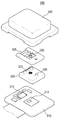
도 11은 도 1 또는 도 8의 옵티컬 핑거 마우스 장치(100, 101)를 이용하여 노트북이나 무선 키보드에 사용 중인 터치 패드를 대체하는 입력 장치를 도시하였다. 입력 장치는 제1 버튼(810), 제2 버튼(820) 및 옵티컬 핑거 마우스(100, 101)를 포함한다.FIG. 11 shows an input device for replacing a touch pad used in a notebook or wireless keyboard using the optical
제1 버튼(810)은 마우스의 우측 버튼과 동일한 기능, 작동을 할 수 있고, 제2 버튼(820)은 마우스의 좌측 버튼과 동일한 기능, 작동을 할 수 있다. 옵티컬 핑거 마우스(100, 101)는 노트북이나 무선 키보드의 터치 패드 부분에 대응될 수 있다. 옵티컬 핑거 마우스(100, 101)는 직경이 작아 목적 물체 하나만 터치할 수 있어 멀티 터치 제스처를 할 수 없지만 클릭이 가능하기 때문에 다양한 기능을 가질 수 있다. 예를 들어, 화면을 확대하거나 축소시키는 줌 인(zoom in), 줌 아웃(zoom out) 기능은 일반적으로 터치 패드에 목적물체 2개를 접촉하여 목적물체 2개를 오므리거나 벌려서 실행시킬 수 있으나, 본 발명에서는 옵티컬 핑거 마우스(100, 101)를 클릭하고 목적물체를 상하 또는 좌우로 기울여 동일한 기능을 실행할 수 있다.The
도 12에서는 제1 버튼(810)이 우측, 제2 버튼(820)이 좌측에 배치되어 있고, 옵티컬 핑거 마우스(100, 101)가 가운데에 배치되어 있으나 이에 한정되는 것은 아니다. 예를 들어, 옵티컬 핑거 마우스(100, 101), 제1 및 제2 버튼(810, 820)이 삼각형 형태로 배치될 수 있다. 옵티컬 핑거 마우스(100, 101), 제1 및 제2 버튼(810, 820)의 배치, 형태 및 크기는 적용되는 전자기기의 크기, 종류, 용도 등에 따라 달라질 수 있다.12, the
이상 첨부된 도면을 참조하여 본 발명의 실시예들을 설명하였으나, 본 발명은 상기 실시예들에 한정되는 것이 아니라 서로 다른 다양한 형태로 제조될 수 있으며, 본 발명이 속하는 기술분야에서 통상의 지식을 가진 자는 본 발명의 기술적 사상이나 필수적인 특징을 변경하지 않고서 다른 구체적인 형태로 실시될 수 있다는 것을 이해할 수 있을 것이다. 그러므로 이상에서 기술한 실시예들은 모든 면에서 예시적인 것이며 한정적이 아닌 것으로 이해해야만 한다.While the present invention has been described in connection with what is presently considered to be practical exemplary embodiments, it is to be understood that the invention is not limited to the disclosed embodiments, but, on the contrary, It is to be understood that the invention may be embodied in other specific forms without departing from the spirit or essential characteristics thereof. It is therefore to be understood that the above-described embodiments are illustrative in all aspects and not restrictive.
100, 101: 옵티컬 핑거 마우스 110: 제1 기판
200, 202: 스위치 201: 제3 기판
210: 돔 스위치 배선 210a: 제1 돔 스위치 배선
210b: 신호 라인 220: 돔 스위치
230: 투명 펫 필름 300, 301: 제1 입력장치
310: 제2 기판 340: 덮개부
350: 전도성 패드 500: 마이크로 터치 패드 장치
510: 기판 540: 터치 패드100, 101: Optical finger mouse 110: First substrate
200, 202: switch 201: third substrate
210:
210b: signal line 220: dome switch
230:
310: second substrate 340:
350: conductive pad 500: micro touch pad device
510: substrate 540: touchpad
Claims (11)
제1 입력 및 제2 입력을 입력받는 제1 입력 장치;및
상기 제1 기판 상면에 배치되고, 상기 목적 물체의 클릭에 반응하는 스위치를 포함하되,
상기 제1 입력 장치는,
상기 스위치 상부에 배치되고, 광원과 이미지센서가 실장된 제2 기판과,
상기 제2 기판 상부에 배치되고, 상기 광원으로부터 출사되어 목적 물체에 반사된 반사광을 투과시키는 광투과부와,
상기 제2 기판 상부에 배치되고, 상기 반사광의 광경로를 조절하는 렌즈와,
상기 제2 기판 상부에 배치되고, 상기 목적 물체가 접촉되는 커버부를 포함하는 옵티컬 핑거 마우스.A first substrate;
A first input device receiving a first input and a second input;
A switch disposed on an upper surface of the first substrate and responsive to a click of the object,
Wherein the first input device comprises:
A second substrate disposed above the switch and having a light source and an image sensor mounted thereon,
A light transmitting portion that is disposed on the second substrate and transmits the reflected light that is emitted from the light source and reflected by the object,
A lens disposed on the second substrate for adjusting an optical path of the reflected light,
And a cover portion disposed on the second substrate and in contact with the object.
상기 제1 입력은, 상기 제1 입력 장치 상에서 상기 목적 물체의 수직 방향의 움직임을 포함하고,
상기 제2 입력은 상기 목적 물체의 스윕(sweep)을 포함하는 옵티컬 핑거 마우스.The method according to claim 1,
Wherein the first input includes a vertical motion of the object on the first input device,
Wherein the second input comprises a sweep of the object.
상기 스위치는 돔 키인 옵티컬 핑거 마우스.The method according to claim 1,
The switch is a domed key optical finger mouse.
터치센서와 연결되고 상기 목적 물체의 터치를 감지하는 전도성 패드를 더 포함하고,
상기 제1 입력은 상기 제1 입력장치를 상기 목적 물체가 터치하는 것을 포함하는 상기 제1 입력는 옵티컬 핑거 마우스.The method according to claim 1,
And a conductive pad connected to the touch sensor and sensing a touch of the object,
Wherein the first input comprises touching the first input device with the object, and the first input comprises an object finger touching the first input device.
상기 전도성 패드는 상기 커버부와 일체형인 옵티컬 핑거 마우스.5. The method of claim 4,
Wherein the conductive pad is integral with the cover portion.
상기 터치 센서와 상기 이미지센서는 일체형인 옵티컬 핑거 마우스.5. The method of claim 4,
Wherein the touch sensor and the image sensor are integrated with each other.
상기 목적 물체의 클릭을 입력으로 인식하는 상기 제1 입력장치 하부에 배치되는 돔 키를 포함하되,
상기 제1 입력장치는,
광원과 이미지센서가 실장된 제2 기판과,
상기 제2 기판 상부에 배치되고, 상기 광원으로부터 출사되어 목적 물체에 반사된 반사광을 투과시키는 광투과부와,
상기 제2 기판 상부에 배치되고, 상기 반사광의 광경로를 조절하는 렌즈와,
상기 제2 기판 상부에 배치되고, 상기 목적 물체가 접촉되는 커버부와,
상기 제2 기판 하부에 배치되고, 상기 목적 물체의 클릭에 반응하는 돔 키를 포함하는 옵티컬 핑거 마우스.A first input device receiving a vertical movement of the object and a horizontal sweep of the object;
And a dome key disposed below the first input device for recognizing a click of the object as an input,
Wherein the first input device comprises:
A second substrate on which a light source and an image sensor are mounted,
A light transmitting portion that is disposed on the second substrate and transmits the reflected light that is emitted from the light source and reflected by the object,
A lens disposed on the second substrate for adjusting an optical path of the reflected light,
A cover portion disposed on the second substrate and contacting the object,
And a dome key disposed below the second substrate and responsive to a click of the object.
터치센서와 연결되고, 상기 목적 물체의 터치를 감지하는 전도성 패드를 더 포함하는 옵티컬 핑거 마우스.8. The method of claim 7,
And a conductive pad connected to the touch sensor and sensing a touch of the object.
상기 전도성 패드는 상기 커버부와 일체형인 옵티컬 핑거 마우스.8. The method of claim 7,
Wherein the conductive pad is integral with the cover portion.
상기 터치 센서와 상기 이미지센서는 일체형인 옵티컬 핑거 마우스.10. The method of claim 9,
Wherein the touch sensor and the image sensor are integrated with each other.
상기 목적 물체에 반사된 광을 입력받고, 상기 돔 키 상부에 배치되는 제1 입력장치를 포함하되,
상기 제1 입력장치는,
광원과 이미지센서가 실장된 제2 기판과,
상기 제2 기판 상부에 배치되고, 상기 광원으로부터 출사되어 목적 물체에 반사된 반사광을 투과시키는 광투과부와,
상기 제2 기판 상부에 배치되고, 상기 반사광의 광경로를 조절하는 렌즈와,
상기 제2 기판 상부에 배치되고, 상기 목적 물체가 접촉되는 커버부를 포함하는 옵티컬 핑거 마우스.A dome key responsive to a click of a destination object; And
And a first input device receiving light reflected from the object and disposed on the dome key,
Wherein the first input device comprises:
A second substrate on which a light source and an image sensor are mounted,
A light transmitting portion that is disposed on the second substrate and transmits the reflected light that is emitted from the light source and reflected by the object,
A lens disposed on the second substrate for adjusting an optical path of the reflected light,
And a cover portion disposed on the second substrate and in contact with the object.
Priority Applications (1)
| Application Number | Priority Date | Filing Date | Title |
|---|---|---|---|
| KR1020120146601A KR20140077607A (en) | 2012-12-14 | 2012-12-14 | Optical finger mouse |
Applications Claiming Priority (1)
| Application Number | Priority Date | Filing Date | Title |
|---|---|---|---|
| KR1020120146601A KR20140077607A (en) | 2012-12-14 | 2012-12-14 | Optical finger mouse |
Publications (1)
| Publication Number | Publication Date |
|---|---|
| KR20140077607A true KR20140077607A (en) | 2014-06-24 |
Family
ID=51129491
Family Applications (1)
| Application Number | Title | Priority Date | Filing Date |
|---|---|---|---|
| KR1020120146601A Withdrawn KR20140077607A (en) | 2012-12-14 | 2012-12-14 | Optical finger mouse |
Country Status (1)
| Country | Link |
|---|---|
| KR (1) | KR20140077607A (en) |
-
2012
- 2012-12-14 KR KR1020120146601A patent/KR20140077607A/en not_active Withdrawn
Similar Documents
| Publication | Publication Date | Title |
|---|---|---|
| KR102367253B1 (en) | Electrical device having multi-functional human interface | |
| US11886699B2 (en) | Selective rejection of touch contacts in an edge region of a touch surface | |
| US20160018911A1 (en) | Touch pen | |
| KR20120094955A (en) | Method and apparatus for changing operating modes | |
| KR20120120097A (en) | Apparatus and method for multi human interface devide | |
| CN103744542B (en) | Hybrid pointing device | |
| KR20170124068A (en) | Electrical device having multi-functional human interface | |
| WO2008144282A1 (en) | Multi-purpose optical mouse | |
| KR20130053364A (en) | Apparatus and method for multi human interface devide | |
| JP2013114645A (en) | Small information device | |
| TWI493386B (en) | Cursor control device and controlling method for starting operating system function menu by using the same | |
| KR20140077607A (en) | Optical finger mouse | |
| AU2013100574B4 (en) | Interpreting touch contacts on a touch surface | |
| KR20190025472A (en) | Electronic device having multi functional human interface and method for controlling the same | |
| KR102171400B1 (en) | Electronic device having multi functional human interface and method for controlling the same | |
| KR20190025471A (en) | Electronic device having multi functional human interface and method for controlling the same | |
| KR20190025470A (en) | Electronic device having multi functional human interface and method for controlling the same | |
| KR20120022378A (en) | Method of controlling terminal device and poingting device using boundary electrode | |
| KR20140058218A (en) | Input device |
Legal Events
| Date | Code | Title | Description |
|---|---|---|---|
| PA0109 | Patent application |
Patent event code: PA01091R01D Comment text: Patent Application Patent event date: 20121214 |
|
| PG1501 | Laying open of application | ||
| PC1203 | Withdrawal of no request for examination | ||
| WITN | Application deemed withdrawn, e.g. because no request for examination was filed or no examination fee was paid |