KR20140077685A - Apparatus and method for compensating chacteristics of transmission in array transmitter - Google Patents
Apparatus and method for compensating chacteristics of transmission in array transmitter Download PDFInfo
- Publication number
- KR20140077685A KR20140077685A KR1020120146756A KR20120146756A KR20140077685A KR 20140077685 A KR20140077685 A KR 20140077685A KR 1020120146756 A KR1020120146756 A KR 1020120146756A KR 20120146756 A KR20120146756 A KR 20120146756A KR 20140077685 A KR20140077685 A KR 20140077685A
- Authority
- KR
- South Korea
- Prior art keywords
- array
- filter
- function
- transmission
- nonlinear
- Prior art date
- Legal status (The legal status is an assumption and is not a legal conclusion. Google has not performed a legal analysis and makes no representation as to the accuracy of the status listed.)
- Withdrawn
Links
- 230000005540 biological transmission Effects 0.000 title claims abstract description 38
- 238000000034 method Methods 0.000 title description 16
- 238000012937 correction Methods 0.000 claims abstract description 59
- 238000005070 sampling Methods 0.000 claims description 3
- 238000012546 transfer Methods 0.000 abstract description 13
- 230000006870 function Effects 0.000 description 41
- 230000003044 adaptive effect Effects 0.000 description 20
- 238000011045 prefiltration Methods 0.000 description 7
- 238000010586 diagram Methods 0.000 description 6
- 238000006243 chemical reaction Methods 0.000 description 3
- 239000000284 extract Substances 0.000 description 3
- 230000001052 transient effect Effects 0.000 description 2
- 230000004075 alteration Effects 0.000 description 1
- 238000004458 analytical method Methods 0.000 description 1
- 238000007796 conventional method Methods 0.000 description 1
- 238000001914 filtration Methods 0.000 description 1
- 238000012986 modification Methods 0.000 description 1
- 230000004048 modification Effects 0.000 description 1
- 238000003672 processing method Methods 0.000 description 1
Images


Classifications
-
- H—ELECTRICITY
- H03—ELECTRONIC CIRCUITRY
- H03F—AMPLIFIERS
- H03F1/00—Details of amplifiers with only discharge tubes, only semiconductor devices or only unspecified devices as amplifying elements
- H03F1/32—Modifications of amplifiers to reduce non-linear distortion
- H03F1/3241—Modifications of amplifiers to reduce non-linear distortion using predistortion circuits
-
- H—ELECTRICITY
- H04—ELECTRIC COMMUNICATION TECHNIQUE
- H04B—TRANSMISSION
- H04B7/00—Radio transmission systems, i.e. using radiation field
- H04B7/02—Diversity systems; Multi-antenna system, i.e. transmission or reception using multiple antennas
- H04B7/04—Diversity systems; Multi-antenna system, i.e. transmission or reception using multiple antennas using two or more spaced independent antennas
- H04B7/06—Diversity systems; Multi-antenna system, i.e. transmission or reception using multiple antennas using two or more spaced independent antennas at the transmitting station
- H04B7/0613—Diversity systems; Multi-antenna system, i.e. transmission or reception using multiple antennas using two or more spaced independent antennas at the transmitting station using simultaneous transmission
- H04B7/0615—Diversity systems; Multi-antenna system, i.e. transmission or reception using multiple antennas using two or more spaced independent antennas at the transmitting station using simultaneous transmission of weighted versions of same signal
- H04B7/0619—Diversity systems; Multi-antenna system, i.e. transmission or reception using multiple antennas using two or more spaced independent antennas at the transmitting station using simultaneous transmission of weighted versions of same signal using feedback from receiving side
-
- H—ELECTRICITY
- H04—ELECTRIC COMMUNICATION TECHNIQUE
- H04L—TRANSMISSION OF DIGITAL INFORMATION, e.g. TELEGRAPHIC COMMUNICATION
- H04L27/00—Modulated-carrier systems
- H04L27/32—Carrier systems characterised by combinations of two or more of the types covered by groups H04L27/02, H04L27/10, H04L27/18 or H04L27/26
- H04L27/34—Amplitude- and phase-modulated carrier systems, e.g. quadrature-amplitude modulated carrier systems
- H04L27/36—Modulator circuits; Transmitter circuits
- H04L27/366—Arrangements for compensating undesirable properties of the transmission path between the modulator and the demodulator
- H04L27/367—Arrangements for compensating undesirable properties of the transmission path between the modulator and the demodulator using predistortion
Landscapes
- Engineering & Computer Science (AREA)
- Computer Networks & Wireless Communication (AREA)
- Signal Processing (AREA)
- Physics & Mathematics (AREA)
- Nonlinear Science (AREA)
- Power Engineering (AREA)
- Transmitters (AREA)
Abstract
본 발명은 유선 혹은 무선 시스템의 다중 배열 송신기에서 송신 신호를 효율적으로 전송하기 위한 송신 특성 보상에 있어서, 비선형 전치 필터와 전달함수 보정용 필터를 각각 독립적으로 송신 경로에 설치하여 신호의 크기에 따라 비선형성이 결정되는 고출력 전력 증폭 장치를 선형화하기 위한 복소 보정값과, 배열 송신기 간의 전달특성을 일치시키기 위한 복소 보정값을 적응적으로 적용하고, 임의의 송신 필터 특성을 적응적으로 적용함으로써, 송신기의 선형화와 배열 오차 보정을 위한 부가적인 디지털 회로의 수를 줄일 수 있다. 또한, 본 발명에서는 배열 오차 보정 기능과 비선형 보정 기능을 하나의 다기능 필터에 의해 수행하도록 함으로써, 종래 배열 오차 보정 기능과 비선형 보정 기능이 별개의 전치 필터에 의해 동작함에 따라 발생하는 불필요한 디지털 회로의 증가를 방지할 수 있어 구현비용을 절감할 수 있으며, 보다 효율적으로 송신신호를 전송할 수 있다. The present invention relates to a transmission characteristic compensation for efficiently transmitting a transmission signal in a multi-array transmitter of a wired or wireless system, in which a nonlinear transpose filter and a transfer function correction filter are independently installed in a transmission path, Adaptively applying a complex correction value for linearizing the determined high output power amplifying device and a complex correction value for matching transmission characteristics between the array transmitters and adaptively applying an arbitrary transmit filter characteristic, And the number of additional digital circuits for correcting the alignment errors. Further, in the present invention, by performing the alignment error correcting function and the nonlinear correcting function with one multifunction filter, it is possible to increase the number of unnecessary digital circuits generated due to the operation of the conventional alignment error correcting function and the non- It is possible to reduce the implementation cost and transmit the transmission signal more efficiently.
Description
본 발명은 유선 혹은 무선 시스템에서 송신신호를 효율적으로 전송하는 방법에 관한 것으로, 특히 비선형 전치 필터와 전달함수 보정용 필터를 각각 독립적으로 송신 경로에 설치하여 신호의 크기에 따라 비선형성이 결정되는 고출력 전력 증폭 장치를 선형화하기 위한 복소 보정값과, 배열 송신기 간의 전달특성을 일치시키기 위한 복소 보정값을 적응적으로 적용하고, 임의의 송신 필터 특성을 적응적으로 적용함으로써, 송신기의 선형화와 배열 오차 보정을 위한 부가적인 디지털 회로의 수를 줄일 수 있도록 하는 다중 배열 송신기에서 송신 특성 보상 방법 및 장치에 관한 것이다.
More particularly, the present invention relates to a method for efficiently transmitting a transmission signal in a wired or wireless system, and more particularly, to a method and apparatus for efficiently transmitting a transmission signal in a wired or wireless system, in which a nonlinear transient filter and a transfer function correction filter are independently provided in a transmission path, Adaptively applying the complex correction value for linearizing the amplifying device and the complex correction value for matching the transmission characteristics between the array transmitter and adaptively applying the arbitrary transmission filter characteristic, the transmitter linearization and the array error correction And more particularly, to a method and apparatus for compensating transmission characteristics in a multi-array transmitter.
일반적으로, 고출력 전력 증폭기의 선형화 방법에는 복소 이득 기반의 디지털 전치 왜곡 방법과 다항식 기반의 디지털 전치 왜곡 방법 등이 있다.Generally, linearization methods of high power amplifiers include a complex gain-based digital predistortion method and a polynomial-based digital predistortion method.
이러한 복소 이득 기반의 디지털 전치 왜곡 방법은 전력 증폭기의 비선형 왜곡을 개선하기 위해 입력 신호와 비선형 왜곡 신호를 적응적으로 비교하여 각 입력 크기에 따른 복소 보정값을 계산하여 실시간 송신 신호에 보정하는 방법이고, 다항식 기반의 디지털 전치 왜곡 방법은 전력 증폭기의 비선형 왜곡 성분을 수차의 다항식으로 근사화하여 다항식의 계수를 입출력 신호로부터 적응적으로 계산하여 전력 증폭기의 역 전달함수를 계산한 후, 이를 송신신호에 보정하는 방법이다.The digital predistortion method based on the complex gain is a method of adaptively comparing the input signal and the nonlinear distortion signal in order to improve the nonlinear distortion of the power amplifier, calculating a complex correction value according to each input size, , A polynomial-based digital predistortion method approximates a nonlinear distortion component of a power amplifier with a polynomial of aberration to adaptively calculate a polynomial coefficient from an input / output signal to calculate an inverse transfer function of the power amplifier, .
또한, 고출력 전력 증폭기의 선형화 방법에는 스마트 안테나 적용의 예에서 배열 송신 RF 시스템의 전달함수를 추정하여 각 송신기의 입력에 복소 계수로서 곱하여 배열 송신 시스템의 전달함수를 동일하게 유지하는 방법도 있다.Also, in the linearization method of a high output power amplifier, there is a method of estimating a transfer function of an array transmission RF system by an example of application of a smart antenna, and multiplying the input of each transmitter as a complex coefficient to maintain the transfer function of the array transmission system.
그러나, 위와 같은 종래 방법에서는 배열 안테나 시스템에서 배열 오차 보정 기능과 비선형 보정 기능이 별개의 전치 필터에 의해 동작하기 때문에 디지털 회로에 의해 필터를 구현하는 경우 디지털 회로의 수가 증가하고 그에 따른 구현 비용이 증가되어 비효율적인 문제점이 있었다.However, in the conventional method as described above, since the array error correction function and the nonlinear correction function are operated by the separate prefilter in the array antenna system, when the filter is implemented by the digital circuit, the number of digital circuits increases, Which is inefficient.
도 1은 종래 기술에 따른 비선형 전치 필터가 내장된 배열 송신 시스템의 상세 회로 구성을 도시한 것이다. 1 shows a detailed circuit configuration of an array transmission system in which a nonlinear transducer according to the prior art is incorporated.
도 1에 도시된 바와 같이, 종래의 기술에 의한 비선형 전치 필터가 내장된 배열 송신 시스템은, 배열보상기(101), 전치필터(103), RF송신기(104), 전력증폭기(105), 적응알고리즘 수행기(106), 배열 오차 보정 알고리즘 수행기(107), 스위치(108)로 구성된다. 1, an array transmission system in which a nonlinear transducer according to the prior art is incorporated includes an
배열보상기(101)는 배열 오차 보정 알고리즘 수행기(107)에서 계산된 복소 배열 오차 보정 계수를 이용하여 단일대역에서 곱셈기 및 지연경로를 용하여 필터 기능을 통해 오차를 보정한다.The
배열 송신기(102)는 전치필터(103), RF 송신기(104), 전력증폭기(105), 적응 알고리즘 수행기(106) 등을 포함한다.The
적응 알고리즘 수행기(106)는 RF송신기(104) 및 전력증폭기(105)의 비선형 특성을 보상하기 위해 전치 필터(103)의 입력 신호와 전력증폭기(105)의 출력 신호로부터 비선형 보정 계수를 적응적 알고리즘으로 계산한다. 전치 필터(103)는 적응 알고리즘 수행기(106)에서 계산되어진 비선형 보정 계수를 이용하여 송신기의 비선형성을 보정한다. The
이러한 배열 송신기(102)에 포함된 비선형 적응 알고리즘 수행기(106)와 실시간 보정을 수행하는 전치 필터(103)는 배열 송신기(102)와는 무관하게 각 송신기의 비선형 특성을 개별적으로 보정하는 기능을 수행하므로 많은 수의 배열 송신기를 구성하는 시스템의 경우 상당한 하드웨어 복잡도를 가지게 된다. The nonlinear
이러한 전치 필터(103)가 내장된 배열 송신기(102)의 배열 오차를 보정하기 위해 종래의 배열 송신기 구조는 배열 오차 알고리즘 수행기(107)을 통해 전달 함수를 추정하고, 이의 역함수를 정규화한 보정계수를 추출한 후, 각 배열 송신기(102)의 배열보상기(101)에 입력하여 오차를 보정하는 구조를 가지게 된다. In order to correct the arrangement error of the
그러나, 위와 같은 구조는 비선형 보정과 배열 보정이 상호 무관하게 동작함에 따른 하드웨어의 비용증가와 비효율적인 구현방안이 된다.
However, the above-described structure is an inefficient implementation method and an increase in hardware cost due to non-linear compensation and arrangement compensation.
따라서, 본 발명은 비선형 전치 필터와 전달함수 보정용 필터를 각각 독립적으로 송신 경로에 설치하여 신호의 크기에 따라 비선형성이 결정되는 고출력 전력 증폭 장치를 선형화하기 위한 복소 보정값과, 배열 송신기 간의 전달특성을 일치시키기 위한 복소 보정값을 적응적으로 적용하고, 임의의 송신 필터 특성을 적응적으로 적용함으로써, 송신기의 선형화와 배열 오차 보정을 위한 부가적인 디지털 회로의 수를 줄일 수 있도록 하는 다중 배열 송신기에서 송신 특성 보상 방법 및 장치를 제공하고자 한다.
Accordingly, the present invention provides a complex correction value for linearizing a high-output power amplifier in which nonlinearity is determined according to a signal size by installing a nonlinear transient filter and a transfer function correction filter independently in a transmission path, Adaptively applying a complex correction value to match the transmit filter characteristics and adaptively applying any transmit filter characteristics to reduce the number of additional digital circuits for linearization of the transmitter and correction of the alignment errors And to provide a transmission characteristic compensation method and apparatus.
상술한 본 발명은 다배열 송신기의 송신 특성 보상장치로서, 다수의 배열 송신기와, 상기 다수의 배열 송신기로부터의 출력신호를 샘플링하여 각 배열 송신기의 출력 신호를 분기하는 배열 스위치와, 상기 배열 스위치로부터 인가되는 각 배열 송신기의 출력신호와 상기 각 배열 송신기로 인가된 입력신호를 분석하여 상기 출력신호의 비선형 오차와 배열 오차를 보정하기 위한 보정 계수를 추출하는 다기능 계수 추출기와, 상기 다기능 계수 추출기로부터 추출된 상기 보정 계수를 이용하여 상기 각 배열 송신기의 비선형 오차와 배열 오차를 보정하는 다기능 필터를 포함한다.The present invention relates to an apparatus for compensating transmission characteristics of a multi-array transmitter, comprising: a plurality of array transmitters; an array switch for sampling output signals from the plurality of array transmitters and for splitting output signals of the array transmitters; A multi-function coefficient extractor for extracting a correction coefficient for correcting a non-linear error and an arrangement error of the output signal by analyzing an output signal of each of the applied array transmitters and an input signal applied to each of the array transmitters, And a multifunction filter for correcting the non-linear errors and the array errors of the respective array transmitters using the correction coefficients.
또한, 상기 다기능 계수 추출기는, 상기 각 배열 송신기의 비선형 오차를 보정하기 위한 보정 계수를 추출하는 비선형 적응 알고리즘 수행기와, 상기 각 배열 송신기의 전달함수를 추정하여 상기 각 배열 송신기의 배열 오차를 보정하는 위한 보정 계수를 추출하는 배열 오차 보정 알고리즘 수행기를 포함하는 것을 특징으로 한다.The multifunctional coefficient extractor includes a nonlinear adaptive algorithm executing unit for extracting a correction coefficient for correcting a nonlinear error of each of the array transmitters and a nonlinear adaptive algorithm executing unit for estimating a transfer function of each of the array transmitters, And an arithmetic error correction algorithm executing unit for extracting a correction coefficient for the arithmetic operation.
또한, 상기 다기능 계수 추출기는, 상기 각 배열 송신기로 인가되는 입력신호와 상기 각 배열 송신기로부터 출력되는 출력 신호간 동기를 일치시키는 동기부와, 상기 일반적인 적응형 필터 기능을 수행하는 적응형 디지털 필터 수행기를 더 포함하는 것을 특징으로 한다.한다.The multi-function coefficient extractor may further include a synchronization unit for synchronizing an input signal applied to each of the array transmitters and an output signal output from each of the array transmitters, and an adaptive digital filter performer Further comprising:
또한, 상기 다기능 필터는, 상기 각 배열 송신기로 인가되는 입력신호의 크기를 계산하는 신호크기 계산기와, 상기 입력신호에 상기 다기능 계수 추출기로부터 인가되는 보정 계수를 곱셈시키는 곱셈기와, 상기 입력신호와 보정 계수가 곱셈된 각 배열 송신기로부터의 출력신호를 더하는 덧셈기를 포함하는 것을 특징으로 한다.The multifunction filter may further include a signal size calculator for calculating a magnitude of an input signal applied to each of the array transmitters, a multiplier for multiplying the input signal by a correction coefficient applied from the multifunctional coefficient extractor, And an adder for adding an output signal from each array transmitter multiplied by the coefficient.
또한, 상기 다기능 필터는, 소정 제어에 따라 상기 입력신호에 대한 상기 보정 계수의 곱셈 수행 여부를 선택적으로 수행시키는 다기능 스위치부를 더 포함하는 것을 특징으로 한다.The multi-function filter may further include a multi-function switch unit for selectively performing multiplication of the correction coefficient with respect to the input signal according to a predetermined control.
또한, 본 발명은 다배열 송신기의 송신 특성 보상 방법으로서, 다수의 배열 송신기로부터의 출력신호를 샘플링하여 각 배열 송신기의 출력 신호를 분기하는 단계와, 상기 각 배열 송신기의 출력신호와 상기 각 배열 송신기로 입력된 입력신호를 분석하는 단계와, 상기 분석을 통해 상기 출력신호의 비선형 오차와 배열 오차를 보정하기 위한 보정 계수를 추출하는 단계와, 상기 보정 계수를 이용하여 상기 각 배열 송신기의 비선형 오차와 배열 오차를 보정하는 단계를 포함한다.The present invention also provides a method of compensating transmission characteristics of a multi-array transmitter, comprising the steps of sampling output signals from a plurality of array transmitters and branching the output signals of the array transmitters, Extracting a correction coefficient for correcting the non-linear error and the arrangement error of the output signal through the analysis; analyzing the non-linear error and the non-linear error of the array transmitter using the correction coefficient; And correcting the array error.
또한, 상기 보정 계수를 추출하는 단계에서, 상기 각 배열 송신기로 인가되는 입력신호와 상기 각 배열 송신기로부터 출력되는 출력 신호간 동기를 일치시키는 단계가 선행되는 것을 특징으로 한다.
The step of extracting the correction coefficient may be preceded by a step of synchronizing an input signal applied to each of the array transmitters and an output signal outputted from each of the array transmitters.
본 발명은 유선 혹은 무선 시스템의 다중 배열 송신기에서 송신 신호를 효율적으로 전송하기 위한 송신 특성 보상에 있어서, 비선형 전치 필터와 전달함수 보정용 필터를 각각 독립적으로 송신 경로에 설치하여 신호의 크기에 따라 비선형성이 결정되는 고출력 전력 증폭 장치를 선형화하기 위한 복소 보정값과, 배열 송신기 간의 전달특성을 일치시키기 위한 복소 보정값을 적응적으로 적용하고, 임의의 송신 필터 특성을 적응적으로 적용함으로써, 송신기의 선형화와 배열 오차 보정을 위한 부가적인 디지털 회로의 수를 줄일 수 있는 이점이 있다.The present invention relates to a transmission characteristic compensation for efficiently transmitting a transmission signal in a multi-array transmitter of a wired or wireless system, in which a nonlinear transpose filter and a transfer function correction filter are independently installed in a transmission path, Adaptively applying a complex correction value for linearizing the determined high output power amplifying device and a complex correction value for matching transmission characteristics between the array transmitters and adaptively applying an arbitrary transmit filter characteristic, And the number of additional digital circuits for correcting the array error can be reduced.
또한, 본 발명에서는 배열 오차 보정 기능과 비선형 보정 기능을 하나의 다기능 필터에 의해 수행하도록 함으로써, 종래 배열 오차 보정 기능과 비선형 보정 기능이 별개의 전치 필터에 의해 동작함에 따라 발생하는 불필요한 디지털 회로의 증가를 방지할 수 있어 구현비용을 절감할 수 있으며, 보다 효율적으로 송신신호를 전송할 수 있는 이점이 있다.
Further, in the present invention, by performing the alignment error correcting function and the nonlinear correcting function with one multifunction filter, it is possible to increase the number of unnecessary digital circuits generated due to the operation of the conventional alignment error correcting function and the non- It is possible to reduce the implementation cost, and there is an advantage that the transmission signal can be transmitted more efficiently.
도 1은 종래 비선형 전치 필터가 내장된 배열 송신 시스템의 구성도,
도 2는 본 발명의 실시예에 따른 비선형 보정을 위한 전치필터와 배열 오차 보정용 필터가 결합된 배열 송신 시스템의 구성도,
도 3은 본 발명의 실시예에 따른 다기능 필터의 상세 회로 구성도,
도 4는 본 발명의 실시예에 따른 다기능 필터내 다기능 스위치부의 상세 회로 구성도.1 is a configuration diagram of an array transmission system incorporating a conventional nonlinear transducer,
FIG. 2 is a configuration diagram of an array transmission system in which a pre-filter for non-linear correction and a filter for correcting an array error are combined according to an embodiment of the present invention;
3 is a detailed circuit diagram of a multifunction filter according to an embodiment of the present invention,
4 is a detailed circuit diagram of a multifunction switch in a multifunctional filter according to an embodiment of the present invention;
이하, 첨부된 도면을 참조하여 본 발명의 동작 원리를 상세히 설명한다. 하기에서 본 발명을 설명함에 있어서 공지 기능 또는 구성에 대한 구체적인 설명이 본 발명의 요지를 불필요하게 흐릴 수 있다고 판단되는 경우에는 그 상세한 설명을 생략할 것이다. 그리고 후술되는 용어들은 본 발명에서의 기능을 고려하여 정의된 용어들로서 이는 사용자, 운용자의 의도 또는 관례 등에 따라 달라질 수 있다. 그러므로 그 정의는 본 명세서 전반에 걸친 내용을 토대로 내려져야 할 것이다.Hereinafter, the operation principle of the present invention will be described in detail with reference to the accompanying drawings. In the following description of the present invention, detailed description of known functions and configurations incorporated herein will be omitted when it may make the subject matter of the present invention rather unclear. The following terms are defined in consideration of the functions of the present invention, and may be changed according to the intentions or customs of the user, the operator, and the like. Therefore, the definition should be based on the contents throughout this specification.
도 2는 본 발명의 실시예에 따른 비선형 보정을 위한 전치필터와 배열 오차 보정용 필터가 결합된 배열 송신 시스템의 구성도 이다.2 is a configuration diagram of an array transmission system in which a pre-filter for nonlinear correction and a filter for correcting an alignment error are combined according to an embodiment of the present invention.
위 도 2를 참조하면, 본 발명의 배열 송신 시스템은 배열 송신기(201)와 배열 스위치(210), 다기능 계수 추출기(205), 비선형 적응 알고리즘 수행기(206), 배열 오차 보정 알고리즘 수행기(207), 적응형 디지털 필터 수행기(208), 스위치(209) 등을 포함할 수 있다.2, an array transmission system according to the present invention includes an
이하, 도 2를 참조하여 본 발명의 배열 송신 시스템의 각 구성요소에서의 동작을 상세히 설명하기로 한다.Hereinafter, operation of each component of the array transmission system of the present invention will be described in detail with reference to FIG.
먼저, 배열 송신기(201)는 다기능 필터(202), RF 송신기(203), 전력증폭기(204) 등을 포함한다.First, the
다기능 필터(202)는 RF 송신기(203)와 전력증폭기(204)의 비선형 특성을 보상하여 배열 송신기(201)의 오차를 보정한다.The
배열 스위치(210)는 배열 송신기(201)의 출력신호를 샘플링하여 각 배열 송신기(201) 출력 신호를 분기한다. The array switch 210 samples the output signal of the
다기능 계수 추출기(205)는 배열 스위치(210)의 출력 신호와 배열 송신기(201)로 인가되는 입력 신호로부터 다기능 계수를 추출한다.The
비선형 적응 알고리즘 수행기(206)는 비선형 보정 계수를 추출하며, 배열 오차 보정 알고리즘 수행기(207)는 배열 오차를 보정하는 보정계수를 추출한다.The nonlinear adaptive algorithm implementer 206 extracts nonlinear correction coefficients, and the array error correction algorithm implementer 207 extracts correction coefficients for correcting the array error.
적응형 디지털 필터 수행기(208)는 적응적 필터기능을 수행하고, 스위치(209)는 비선형 적응 수행, 배열 오차 보정, 적응적 필터 기능 등을 사용자의 선택 입력에 따라 스위칭 선택할 수 있다. The adaptive digital filter performer 208 performs an adaptive filter function, and the
이에 따라, 사용자는 배열 송신기(201)가 동작하는 모드를 결정하여 다기능 계수 추출기(205)의 기능을 선택하고, 위와 같이 기능이 선택되는 경우, 선택된 기능에 의해 수행되어진 알고리즘으로부터 여러 가지 보정 계수가 추출되어 다기능 필터(202)에 적용됨으로써, 배열 송신기(201)의 비선형 보정 및 배열 오차에 대한 보정이 수행되게 된다.Accordingly, the user determines the mode in which the
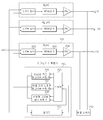
도 3은 본 발명의 실시예에 따라 비선형 보정과 배열 오차 보정을 모두 적용할 수 있는 다기능 필터(202)의 상세 회로 구성을 도시한 것이다.3 shows a detailed circuit configuration of a
도 3을 참조하면, 다기능 필터(202)는 입력 신호의 크기를 계산하는 신호 크기 계산기(301), 비선형 보정 기능과 배열 오차 보정 기능을 선택하는 다기능 스위치부(302), 입력되는 복소 보정 계수를 가중치라 하고 이를 입력 신호와 곱하는 곱셈기(304), 각각의 경로를 합하는 덧셈기(305) 등을 포함할 수 있다.3, the
이하, 도 3을 참조하여 다기능 필터(202)의 각 구성요소에서의 동작을 상세히 설명하기로 한다.Hereinafter, the operation of each component of the
먼저, 다기능 필터(202)로 입력되는 신호는 다기능 스위치부(302)의 기능 선택 여부에 따라 배열 오차 보정 기능으로 동작할 경우, 다기능 스위치(302)가 지연 회로로 동작하여 추정된 전달 함수의 역 함수 필터링 특성을 나타내기 위해 계산된 가중치(303)를 이용하여 디지털 필터 동작을 수행할 수 있게 된다. First, when a signal input to the
또한, 다기능 스위치부(302)의 기능 선택 여부에 따라 비선형 보정 기능으로 동작할 경우, 신호 크기 계산기(301)에서 입력신호의 크기를 계산하고, 다기능 스위치부(302)에서는 신호 크기 계산기(301)에서 계산된 입력 신호 크기값을 곱셈기(304)를 이용하여 곱하는 기능을 수행하게 된다. 따라서, 다기능 필터(202)의 전체적의 출력 동작 특성은 메모리를 갖지 않는 다항식(Polynomial) 비선형 전달 함수를 계산하는 기능으로 동작한다.The
이를 통해 다기능 필터(202)는 디지털 필터와 유사한 구조를 기반으로 디지털 회로를 구현하게 되면, 배열 오차의 전달함수를 보정하기 위한 역 전달함수를 출력하는 필터 기능을 수행할 수 있고, 또한, 비선형 전달함수를 보정하기 위한 메모리가 없는 다항식 전치 필터 기능을 수행할 수 있다.Accordingly, if the digital filter is implemented based on a structure similar to the digital filter, the
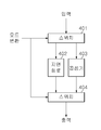
도 4는 본 발명의 실시예에 따른 다기능 필터(202)내 다기능 스위치부(302)의 상세 회로 구성도이다. 4 is a detailed circuit diagram of the
위 도 4에서와 같이, 입력되는 모드 변환 신호에 의해 비선형 보정 기능과 배열 오차 보정 기능을 선택하는 스위치(401), 배열 오차 보정을 위해 선택되는 지연회로(402), 비선형 보정을 위해 선택되는 곱셈기(403), 지연회로(402)와 곱셈기(403)의 출력을 모드 변환 입력에 따라 선택적으로 스위칭 선택하는 스위치(404) 등을 포함할 수 있다.4, a
입력 신호는 모드 변환 신호에 의해 지연 회로(402)와 곱셈기(403)의 어느 한 방향으로 입력되고, 곱셈기(403)는 도 3의 신호 크기 계산기(301)에서 계산된 신호의 크기 계수와 곱해져 출력된다. 이러한 동작은 입력 신호의 분포에 따라 작성되는 룩업테이블(lookup table)로도 구현이 가능하다.The input signal is input to the
상기한 바와 같이, 본 발명은 유선 혹은 무선 시스템의 다중 배열 송신기에서 송신 신호를 효율적으로 전송하기 위한 송신 특성 보상에 있어서, 비선형 전치 필터와 전달함수 보정용 필터를 각각 독립적으로 송신 경로에 설치하여 신호의 크기에 따라 비선형성이 결정되는 고출력 전력 증폭 장치를 선형화하기 위한 복소 보정값과, 배열 송신기 간의 전달특성을 일치시키기 위한 복소 보정값을 적응적으로 적용하고, 임의의 송신 필터 특성을 적응적으로 적용함으로써, 송신기의 선형화와 배열 오차 보정을 위한 부가적인 디지털 회로의 수를 줄일 수 있다. 또한, 본 발명에서는 배열 오차 보정 기능과 비선형 보정 기능을 하나의 다기능 필터에 의해 수행하도록 함으로써, 종래 배열 오차 보정 기능과 비선형 보정 기능이 별개의 전치 필터에 의해 동작함에 따라 발생하는 불필요한 디지털 회로의 증가를 방지할 수 있어 구현비용을 절감할 수 있으며, 보다 효율적으로 송신신호를 전송할 수 있다. As described above, in the transmission characteristic compensation for efficiently transmitting a transmission signal in a multi-array transmitter of a wired or wireless system, a nonlinear transpose filter and a transfer function correction filter are independently provided in a transmission path, Adaptive adaptive application of complex correction values for linearizing a high output power amplifying device whose nonlinearity is determined according to size and a complex correction value for matching transmission characteristics between array transmitters and adaptively applying arbitrary transmit filter characteristics Thereby reducing the number of additional digital circuits for linearizing the transmitter and correcting the alignment error. Further, in the present invention, by performing the alignment error correcting function and the nonlinear correcting function with one multifunction filter, it is possible to increase the number of unnecessary digital circuits generated due to the operation of the conventional alignment error correcting function and the non- It is possible to reduce the implementation cost and transmit the transmission signal more efficiently.
한편 상술한 본 발명의 설명에서는 구체적인 실시예에 관해 설명하였으나, 여러 가지 변형이 본 발명의 범위에서 벗어나지 않고 실시될 수 있다. 따라서 발명의 범위는 설명된 실시 예에 의하여 정할 것이 아니고 특허청구범위에 의해 정하여져야 한다.
While the invention has been shown and described with reference to certain preferred embodiments thereof, it will be understood by those skilled in the art that various changes and modifications may be made without departing from the spirit and scope of the invention. Accordingly, the scope of the invention should not be limited by the described embodiments but should be defined by the appended claims.
201 : 배열 송신기 202 : 다기능 필터
203 : RF송신기 204 : 전력 증폭기
205 : 다기능 계수 추출기 206 : 비선형 적응 알고리즘 수행기
207 : 배열오차보정 알고리즘 수행기 208 : 적응형 디지털필터 수행기
209 : 스위치 210 : 배열 스위치
211 : 동기부201: Array transmitter 202: Multifunction filter
203: RF transmitter 204: power amplifier
205: Multifunctional coefficient extractor 206: Nonlinear adaptive algorithm implementer
207: array error correction algorithm execution unit 208: adaptive digital filter execution unit
209: Switch 210: Array switch
211: Synchronization
Claims (1)
상기 다수의 배열 송신기로부터의 출력신호를 샘플링하여 각 배열 송신기의 출력 신호를 분기하는 배열 스위치와,
상기 배열 스위치로부터 인가되는 각 배열 송신기의 출력신호와 상기 각 배열 송신기로 인가된 입력신호를 분석하여 상기 출력신호의 비선형 오차와 배열 오차를 보정하기 위한 보정 계수를 추출하는 다기능 계수 추출기와,
상기 다기능 계수 추출기로부터 추출된 상기 보정 계수를 이용하여 상기 각 배열 송신기의 비선형 오차와 배열 오차를 보정하는 다기능 필터
를 포함하는 다배열 송신기에서 송신 특성 보상 장치.A plurality of array transmitters,
An array switch for sampling output signals from the plurality of array transmitters and for branching output signals of the array transmitters,
A multi-function coefficient extractor for extracting a correction coefficient for correcting the non-linear error and the arrangement error of the output signal by analyzing an output signal of each of the array transmitters applied from the array switch and an input signal applied to each of the array transmitters,
A multifunctional filter for correcting nonlinear errors and arrangement errors of the respective array transmitters by using the correction coefficients extracted from the multifunctional coefficient extractor
And a transmission characteristic compensator for compensating the transmission characteristic of the multi-array transmitter.
Priority Applications (1)
| Application Number | Priority Date | Filing Date | Title |
|---|---|---|---|
| KR1020120146756A KR20140077685A (en) | 2012-12-14 | 2012-12-14 | Apparatus and method for compensating chacteristics of transmission in array transmitter |
Applications Claiming Priority (1)
| Application Number | Priority Date | Filing Date | Title |
|---|---|---|---|
| KR1020120146756A KR20140077685A (en) | 2012-12-14 | 2012-12-14 | Apparatus and method for compensating chacteristics of transmission in array transmitter |
Publications (1)
| Publication Number | Publication Date |
|---|---|
| KR20140077685A true KR20140077685A (en) | 2014-06-24 |
Family
ID=51129551
Family Applications (1)
| Application Number | Title | Priority Date | Filing Date |
|---|---|---|---|
| KR1020120146756A Withdrawn KR20140077685A (en) | 2012-12-14 | 2012-12-14 | Apparatus and method for compensating chacteristics of transmission in array transmitter |
Country Status (1)
| Country | Link |
|---|---|
| KR (1) | KR20140077685A (en) |
-
2012
- 2012-12-14 KR KR1020120146756A patent/KR20140077685A/en not_active Withdrawn
Similar Documents
| Publication | Publication Date | Title |
|---|---|---|
| EP3089414B1 (en) | Digital pre-distortion parameter obtaining method and pre-distortion system | |
| US8369447B2 (en) | Predistortion with sectioned basis functions | |
| KR100724934B1 (en) | Digital Predistortion Apparatus and Method for Broadband Power Amplifiers | |
| US20110235734A1 (en) | Active antenna array having a single dpd lineariser and a method for predistortion of radio signals | |
| US9099966B2 (en) | Dual time alignment architecture for transmitters using EER/ET amplifiers and others | |
| US10075324B2 (en) | Predistortion processing apparatus and method | |
| US20110235749A1 (en) | Active antenna array having analogue transmitter linearisation and a method for predistortion of radio signals | |
| EP2837093B1 (en) | Digital predistorter (dpd) structure based on dynamic deviation reduction (ddr)-based volterra series | |
| KR20140084290A (en) | Processor having instruction set with user-defined non-linear functions for digital pre-distortion(dpd) and other non-linear applications | |
| JP2009213113A (en) | Apparatus and method for identifying reverse characteristic of nonlinear system, power amplifier, and predistorter of power amplifier | |
| US20110095820A1 (en) | Method for pre-distorting a power amplifier and the circuit thereof | |
| US9853664B2 (en) | Radio frequency power amplification system, radio frequency power amplification method, transmitter, and base station | |
| JP2008294518A (en) | Transmitter | |
| KR20140147023A (en) | Amplification apparatus | |
| KR20130063774A (en) | Digital pre-distortion device and pre-distortion method thereof | |
| KR102097521B1 (en) | High-frequency amplifier and method of compensating distortion | |
| KR20140077685A (en) | Apparatus and method for compensating chacteristics of transmission in array transmitter | |
| JP4939281B2 (en) | Amplifier | |
| KR101470817B1 (en) | Apparatus and method of predistortion of multiple nonlinear amplifiers with single feedback loop | |
| US8417193B2 (en) | Transmitting device and method for determining target predistortion setting value | |
| KR101507923B1 (en) | Behavioral modeling method and decentralized predistortion architecture for wireless communication system with multi-branch rf power amplifier architecture | |
| JP5071168B2 (en) | Distortion compensation coefficient updating apparatus and distortion compensation amplifier | |
| JP5339083B2 (en) | Digital distortion compensation method and circuit | |
| JP2006295440A (en) | Distortion compensation apparatus and delay amount control method | |
| US20150180610A1 (en) | Transmission device and distortion compensation method |
Legal Events
| Date | Code | Title | Description |
|---|---|---|---|
| PA0109 | Patent application |
Patent event code: PA01091R01D Comment text: Patent Application Patent event date: 20121214 |
|
| PG1501 | Laying open of application | ||
| PC1203 | Withdrawal of no request for examination | ||
| WITN | Application deemed withdrawn, e.g. because no request for examination was filed or no examination fee was paid |