KR20140077781A - Lighting device and dimming method using transparent display panel - Google Patents
Lighting device and dimming method using transparent display panel Download PDFInfo
- Publication number
- KR20140077781A KR20140077781A KR1020120146915A KR20120146915A KR20140077781A KR 20140077781 A KR20140077781 A KR 20140077781A KR 1020120146915 A KR1020120146915 A KR 1020120146915A KR 20120146915 A KR20120146915 A KR 20120146915A KR 20140077781 A KR20140077781 A KR 20140077781A
- Authority
- KR
- South Korea
- Prior art keywords
- display panel
- transparent display
- light source
- light
- lighting apparatus
- Prior art date
- Legal status (The legal status is an assumption and is not a legal conclusion. Google has not performed a legal analysis and makes no representation as to the accuracy of the status listed.)
- Granted
Links
Images


Classifications
-
- F—MECHANICAL ENGINEERING; LIGHTING; HEATING; WEAPONS; BLASTING
- F21—LIGHTING
- F21S—NON-PORTABLE LIGHTING DEVICES; SYSTEMS THEREOF; VEHICLE LIGHTING DEVICES SPECIALLY ADAPTED FOR VEHICLE EXTERIORS
- F21S10/00—Lighting devices or systems producing a varying lighting effect
- F21S10/02—Lighting devices or systems producing a varying lighting effect changing colors
- F21S10/023—Lighting devices or systems producing a varying lighting effect changing colors by selectively switching fixed light sources
-
- F—MECHANICAL ENGINEERING; LIGHTING; HEATING; WEAPONS; BLASTING
- F21—LIGHTING
- F21V—FUNCTIONAL FEATURES OR DETAILS OF LIGHTING DEVICES OR SYSTEMS THEREOF; STRUCTURAL COMBINATIONS OF LIGHTING DEVICES WITH OTHER ARTICLES, NOT OTHERWISE PROVIDED FOR
- F21V23/00—Arrangement of electric circuit elements in or on lighting devices
- F21V23/003—Arrangement of electric circuit elements in or on lighting devices the elements being electronics drivers or controllers for operating the light source, e.g. for a LED array
-
- H—ELECTRICITY
- H05—ELECTRIC TECHNIQUES NOT OTHERWISE PROVIDED FOR
- H05B—ELECTRIC HEATING; ELECTRIC LIGHT SOURCES NOT OTHERWISE PROVIDED FOR; CIRCUIT ARRANGEMENTS FOR ELECTRIC LIGHT SOURCES, IN GENERAL
- H05B47/00—Circuit arrangements for operating light sources in general, i.e. where the type of light source is not relevant
- H05B47/10—Controlling the light source
- H05B47/155—Coordinated control of two or more light sources
-
- F—MECHANICAL ENGINEERING; LIGHTING; HEATING; WEAPONS; BLASTING
- F21—LIGHTING
- F21W—INDEXING SCHEME ASSOCIATED WITH SUBCLASSES F21K, F21L, F21S and F21V, RELATING TO USES OR APPLICATIONS OF LIGHTING DEVICES OR SYSTEMS
- F21W2131/00—Use or application of lighting devices or systems not provided for in codes F21W2102/00-F21W2121/00
- F21W2131/30—Lighting for domestic or personal use
-
- F—MECHANICAL ENGINEERING; LIGHTING; HEATING; WEAPONS; BLASTING
- F21—LIGHTING
- F21Y—INDEXING SCHEME ASSOCIATED WITH SUBCLASSES F21K, F21L, F21S and F21V, RELATING TO THE FORM OR THE KIND OF THE LIGHT SOURCES OR OF THE COLOUR OF THE LIGHT EMITTED
- F21Y2115/00—Light-generating elements of semiconductor light sources
- F21Y2115/10—Light-emitting diodes [LED]
Landscapes
- Engineering & Computer Science (AREA)
- General Engineering & Computer Science (AREA)
- Microelectronics & Electronic Packaging (AREA)
- Circuit Arrangement For Electric Light Sources In General (AREA)
Abstract
본 발명은 투명 디스플레이 패널을 이용한 조명 장치에 관한 것으로, 광원(100)과, 상기 광원(100)으로부터 조사되는 빛을 투과하여, 다양한 색상, 이미지, 영상 중의 어느 하나 이상의 형태로 조광하여 방출시키는 투명 디스플레이 패널(120)과, 사용자로부터 입력된 조명 패턴을 상기 투명 디스플레이 패널(120)에서 처리될 수 있는 신호로 변환하여 조광을 제어하는 제어부(210)를 포함하도록 구성하여, 상기 투명 디스플레이 패널(120)의 가시광선 투과 특성과, 전기적 제어 기술에 의해 다양한 색상과, 이미지, 영상 등으로 조명을 연출할 수 있도록 하는 투명 디스플레이 패널을 이용한 조명 장치 및 제어 방법에 관한 것이다.The present invention relates to a lighting apparatus using a transparent display panel, and more particularly, to a lighting apparatus using a transparent display panel, which comprises a light source 100, and a light source 100 which transmits light emitted from the light source 100, A display panel 120 and a control unit 210 for controlling the dimming by converting an illumination pattern input by a user into a signal that can be processed by the transparent display panel 120, The present invention also relates to a lighting apparatus and a control method using the transparent display panel that can display light with various colors, images, and images by an electric control technique.
Description
본 발명은 광원으로부터 조사된 빛이 투명 디스플레이 패널을 투과하여 다양한 색상과, 이미지 및 영상 등의 형태로 조광된 빛을 방출시킴으로써, 다양한 조명 패턴을 연출할 수 있도록 하는 투명 디스플레이 패널을 이용한 조명 장치 및 조광 제어 방법에 관한 것이다.
The present invention relates to a lighting apparatus and a lighting apparatus using a transparent display panel that emits light in various colors, images, and images by transmitting light emitted from a light source through a transparent display panel, And a control method.
현재 가정용 또는 산업용으로 사용되는 조명 장치는 그 방식과 기술에 있어서 모두 열거하기 어려울 정도로 다양한 제품들이 생산, 사용되고 있다.Currently, lighting devices used for domestic or industrial use are produced and used in such a way that it is difficult to enumerate them both in the way and in the technology.
이러한 조명 장치는 다양한 색상의 직물이나, PVC, 유리 등으로 구성되는 투과부재에 광원으로부터 발생된 가시광선을 통과시켜 다양한 종류의 색상을 표현할 수 있도록 구성되며, 상기한 투과재를 통한 색상의 변경 외에도, 조명 장치의 빛을 발생하는 광원 자체를 통해 다양한 색상을 표현하도록 구성된다.Such an illumination device is configured to transmit visible light generated from a light source to a transmissive member composed of various color fabrics, PVC, glass, or the like to express various kinds of colors. In addition to changing the color through the transmissive material , And is configured to express various colors through the light source itself generating the light of the lighting device.
한편, 이러한 조명 장치는 그 특성상 한번 설치되면 조명 장치의 설비를 교체하는 것은 시간적, 비용적 요소로 인해 매우 번거로운 과정으로 여겨져, 실제로 한번 설치된 조명 장치는 특별한 사유가 없는 한 계속 사용되는 것이 일반적이다.On the other hand, due to the characteristics of such a lighting apparatus, once installed, replacing a lighting apparatus is considered to be a very cumbersome process due to time and cost factors, and a lighting apparatus once actually installed is generally used continuously unless there is a special reason.
따라서, 종래의 일반적인 조명 장치는 상기한 광원 및 투과부재가 한번 설치가 완료되면 고정된 색상으로 연출할 수 밖에 없기 때문에, 인간의 감성적, 계절적, 기후적 및 사용 환경적인 요인에 따라 다양한 색상으로 연출할 수가 없는 문제점이 있다.Therefore, since the conventional illumination device can only produce a fixed color when the light source and the transparent member are installed once, it is possible to produce various colors according to human emotional, seasonal, climatic, and environmental factors There is no problem.
상기한 문제점을 해결하기 위한 일예로서, 한국공개특허 2010-0135502에는 조명 장치의 광원인 엘이디가 설치되는 엘이디 기판을 커버링하도록 하는 컬러 필름을 형성하여, 여러 가지의 색상으로 조명을 연출할 수 있도록 구성된 기술이 소개되어 있다.As an example for solving the above problems, Korean Patent Laid-Open Publication No. 2010-0135502 discloses a technology for forming a color film for covering an LED substrate on which an LED as a light source of a lighting device is installed, Is introduced.
상기 기술문헌에서 보는 바와 같이, 종래에는 조명 장치에 설치된 광원의 전면에 미리 정해진 컬러 필터를 장착하거나, 여러 가지 색을 조합한 광원 렌즈 등의 기구적인 조합을 사용하여 색상을 조절하는 방법 등이 사용되고 있으나, 이러한 컬러 필터 및 특수 렌즈 등을 이용한 조명 장치는 매우 고가이며, 전문적인 유지 보수가 필요로 됨에 따라, 방송 기술이나, 무대 조명 기술 등의 특정 용도로만 일부 사용되고 있는 실정이다.As shown in the above technical literatures, conventionally, a method of adjusting a color by mounting a predetermined color filter on a front surface of a light source provided in an illumination device or using a mechanical combination of a light source lens combining various colors is used However, such a lighting device using a color filter and a special lens is very expensive and requires professional maintenance, and thus is used only for a specific purpose such as broadcasting technology and stage lighting technology.
따라서, 조명 장치의 광원 제작의 다양한 방식과, 광원의 제어 방법 및 광원의 전자적, 기구적 발전이 이루어짐에도 불구하고, 조명 장치의 다양한 색상을 비교적 저렴한 가격으로 표현할 수 있는 전자적인 조명 제어 기술은 아직 일반화되지 못하고 있다.Therefore, although various methods of manufacturing a light source of a lighting apparatus, a method of controlling a light source, and an electronic and mechanical development of a light source are performed, an electronic lighting control technology capable of expressing various colors of a lighting apparatus at a relatively low price It is not generalized.
또한, 최근에 들어서 전문적인 무대 환경 뿐만 아니라 일반 가정 환경하에서도 조명의 변화에 따른 인테리어의 심리적인 효과를 높이기 위한 관심이 점차 고조되고 있는 한편, 전시, 시연, 판매장 등의 산업 분야에서도 좀 더 다양한 색감의 조명 장치 기술의 지속적인 발전이 요구되어지고 있으며, 이러한 기술적 발전에 대응하는 시장이 형성되어 광범위한 산업 파급력을 유지해 오고 있는 등 해당 기술의 개발이 시급히 요구되고 있는 상황이다.
In recent years, there has been a growing interest in enhancing the psychological effect of the interior according to the change of lighting not only in the professional stage environment but also in the ordinary household environment, but also in the industrial fields such as exhibition, demonstration, The development of color lighting equipment technology is required to be continuously developed, and a market to cope with such technological developments has been formed, and a wide range of industrial power has been maintained.
이에 상기와 같은 점을 감안하여 발명된 본 발명은 투명 디스플레이 패널의 가시광선 투과 특성을 컬러 필터로 사용하여, 광원에서 발생된 빛이 투명 디스플레이 패널를 통과하여 외부로 색상을 방출하도록 함으로써, 한 대의 조명 장치를 통해서 디스플레이 패널이 표현 가능한 모든 다양한 색상과, 이미지, 영상 등으로 조명의 연출이 가능한 특징이 있는 투명 디스플레이 패널을 이용한 조명 장치 및 조광 제어 방법을 제공함을 목적으로 한다.
In view of the above, the present invention, which has been developed in view of the above, uses visible light transmission characteristics of a transparent display panel as a color filter to allow light emitted from a light source to pass through a transparent display panel and emit color to the outside, An object of the present invention is to provide a lighting apparatus and a dimming control method using a transparent display panel having a feature that a display panel can be represented by all various colors, images, images, and the like through an apparatus.
상기와 같은 목적을 달성하기 위한 본 발명에 따르면, 광원과, 상기 광원으로부터 조사되는 빛을 투과하여, 다양한 색상, 이미지, 영상 중 어느 하나 이상의 형태로 조광하여 방출시키는 투명 디스플레이 패널과, 사용자로부터 입력된 조명 패턴을 상기 투명 디스플레이 패널에서 처리될 수 있는 신호로 변환하여 조광을 제어하는 제어부를 포함하는 투명 디스플레이 패널을 이용한 조명 장치가 제공된다.According to an aspect of the present invention, there is provided a display device including: a light source; a transparent display panel that transmits light emitted from the light source and emits light by emitting light in at least one of various colors, images, And a control unit for converting the illuminated pattern into a signal that can be processed in the transparent display panel to control dimming.
또한, 본 발명에 따르면 사용자가 원하는 조명 패턴 정보를 입력 받는 사용자 입력단계와, 상기 사용자에 의해 입력된 조명 패턴을 영상으로 표현하기 위한 데이터를 처리하는 데이터처리단계와, 상기 영상으로 표현하기 위해 처리된 데이터를 투명 디스플레이 패널에 의해 처리 될 수 있는 디지털 신호로 변환하는 신호변환단계 및 상기 변환된 디지털 신호에 의해 상기 투명 디스플레이 패널을 제어하여, 광원으로부터 조사되는 빛을 다양한 색상, 이미지, 영상 중의 어느 하나 이상의 형태로 조광시키는 조광제어단계로 이루어지는 투명 디스플레이 패널을 이용한 조명 장치의 조광 제어 방법이 제공된다.
According to another aspect of the present invention, there is provided a method for processing an image, the method comprising: a user input step of inputting desired illumination pattern information by a user; a data processing step of processing data for representing an illumination pattern input by the user; And converting the converted data into a digital signal that can be processed by the transparent display panel, and controlling the transparent display panel by the converted digital signal to convert the light emitted from the light source into any one of various colors, There is provided a dimming control method for a lighting apparatus using a transparent display panel comprising a dimming control step of dimming at least one shape.
이러한 본 발명에 따른 투명 디스플레이 패널을 이용한 조명 장치 및 조광 제어 방법에 의하면, 조명 장치를 설치한 후에는 한 대의 장치에서 투명 디스플레이 패널이 표현 가능한 모든 다양한 색상이나, 이미지, 영상 등의 다양한 조명 패턴으로 연출이 가능하므로, 다양한 용도로 사용이 가능하다.According to the illumination device and the light control method using the transparent display panel according to the present invention, after the illumination device is installed, a variety of illumination patterns, such as all colors, images, and images, Because it can be directed, it can be used for various purposes.
또한 본 발명에 따르면, 투명 디스플레이 패널이 고가의 컬러 필터를 대신하는 역할을 함으로써, 비용 측면에서 이점을 가지며, 특히, 전문적인 설비의 교체나, 유지 보수가 필요 없어 유지 관리 비용을 줄일 수 있는 효과가 있다.In addition, according to the present invention, since the transparent display panel plays the role of replacing the expensive color filter, it has an advantage in terms of cost, and in particular, it does not require replacement or maintenance of professional facilities, .
또한, 본 발명에 따르면, 투명 디스플레이 패널을 통한 다양한 표현의 효과를 통해 백화점, 전시회 등과 같은 산업 현장에서 고객의 구매 의욕을 환기시킴으로써, 매출을 증대시킬 수 있는 효과가 있다.Also, according to the present invention, it is possible to increase sales by attracting customers' desire to purchase at an industrial site such as a department store, an exhibition, etc. through the effect of various expressions through the transparent display panel.
또한, 본 발명에 따르면, 일반 가정의 실내에서 다양한 분위기를 연출할 수 있도록 함으로써, 인간의 감성을 자극하는 안락한 주거 환경을 제공할 수 있도록 하는 효과가 있다.
Further, according to the present invention, a variety of atmospheres can be produced in a room of a general home, thereby providing a comfortable living environment that stimulates human emotion.
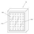
도 1은 본 발명의 일실시예에 따른 조명 장치를 나타낸 사시도
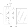
도 2는 도 1에 나타낸 조명 장치의 측단면 형상을 나타낸 단면도.
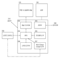
도 3은 본 발명의 일실시예에 따른 조명 장치의 제어부를 나타낸 블록도.
도 4는 본 발명의 일변형예에 따른 조명 장치를 나타낸 사시도.
도 5는 본 발명에 의한 조명 장치의 조광 제어 방법을 나타낸 순서도.1 is a perspective view showing a lighting apparatus according to an embodiment of the present invention;
2 is a cross-sectional view showing a side cross-sectional shape of the lighting apparatus shown in Fig.
3 is a block diagram showing a control unit of a lighting apparatus according to an embodiment of the present invention;
4 is a perspective view showing a lighting apparatus according to a modification of the present invention;
5 is a flowchart showing a dimming control method of a lighting apparatus according to the present invention.
이하 본 발명의 실시예를 첨부된 예시도면을 참조로 상세히 설명하며, 이러한 실시예는 일례로서 본 발명이 속하는 기술 분야에서 통상의 지식을 가진 자가 여러 가지 상이한 형태로 구현될 수 있으므로, 여기에서 설명하는 실시예에 한정되지 않는다.Hereinafter, exemplary embodiments of the present invention will be described in detail with reference to the accompanying drawings, which illustrate exemplary embodiments of the present invention. The present invention is not limited to these embodiments.
도 1은 본 발명의 일실시예에 따른 조명 장치를 나타낸 것으로, 특히, 투명 디스플레이 패널을 사용한 조명부의 외곽을 이루는 개념적인 구조를 나타낸 도면이다.FIG. 1 illustrates a lighting device according to an exemplary embodiment of the present invention. In particular, FIG. 1 illustrates a conceptual structure of a lighting unit using a transparent display panel.
도 1을 참조하면, 본 발명의 일실시예에 따른 조명 장치는 외장 샤시(110)와, 광원(100) 및 투명 디스플레이 패널(120)을 포함한다.Referring to FIG. 1, a lighting apparatus according to an embodiment of the present invention includes an
상기 외장 샤시(110)는 조명 장치(10)의 외곽의 형상을 이루는 동시에 내부에 상기 광원(100)을 포함한 조명 장치의 구성 부품들을 설치할 수 있는 공간을 형성하며, 어느 일측으로는 빛을 조사할 수 있도록 개구 또는 개방된 구조를 이루도록 구성될 수 있다.The
상기 광원(100)은 상기 외장 샤시(110)에 설치되어 고정된 빛을 발광하도록 하는 발광다이오드(LED)나, 기존의 벌브(Bulb) 타입의 전구 또는 크세논(Xenon) 램프 등 다양한 형태의 광원(100)으로 구성될 수 있다.The
상기 투명 디스플레이 패널(120)은 조명 장치(10)를 통해 조광하고자 하는 색상이나 모양 등을 연출할 수 있도록 구성되어, 상기 광원(100)의 빛이 조사되는 전방에 설치되어 조명 장치(10)의 컬러 필터의 역할을 한다.The
참고로, 상기 투명 디스플레이 패널(120)은 투명한 패널에 발광트렌지스터나, 유기 화합물을 증착시켜, 전원이 투입되면 발광을 하는 원리를 사용한 것으로써, 디스플레이의 특성상 기존의 TFT-LCD 패널에 비하여 색재현율, 해상도, 명암비 등의 성능이 다소 떨어지지만, 패널의 투명한 특성으로 인하여 전후면에 가시광선의 투과성이 우수한 특징이 있어, 모바일 장치, 차세대 디스플레이 장치 등의 다양한 용도로 활용 되고 부품이다.For reference, the
이러한 투명 디스플레이 패널(120)은 전원이 인가되지 않는 상태에서도 100%의 가시광선의 투과율을 가지진 못하지만, 이는 필름 상태의 원판 패널에 영상을 표시하기 위하여 빛이 발광할 수 있도록 다양한 반도체 공정 또는 유기화합물 공정을 거치기 때문인데, 그 결과 패널 자체가 일반 유리에 비하여 약간 흐리게 보이는 특성을 가지고 있으며, 다양한 공정 기술의 개선으로 향후에는 그 투명도가 점점 개선될 가능성이 높다.Although the
본 발명은 상기 투명 디스플레이 패널(120)의 우수한 가시광선 투과성을 이용하여, 조명 장치(10)의 컬러 필터의 역할을 하도록 함으로써, 상기 광원(100)으로부터 조사된 빛이 상기 투명 디스플레이 패널(120)을 통과하여 외부로 조광에 의한 색상을 방출하도록 구성한 것이다.The
또한, 본 발명에 따른 조명 장치(10)는 기구적인 결합체의 회전, 구동 등이 없이 모든 부분이 전자적으로 제어가 가능하고, 다양한 색상을 표현할 수 있으며, 투명 디스플레이 패널(120)이 구현할 수 있는 색상의 깊이(Depth)와 해상도(Resolution) 만큼의 자연스러운 색상을 표현할 수 있는 조명 장치(10)를 구현할 수 있다.In addition, the
또한, 모든 부분이 전자적으로 제어가 가능함으로써, 조명 장치(10)의 기구적인 결합을 이루는 구성의 존재에 따라 필요한 전문적인 설정 과정이나, 유지 보수 과정이 대폭 축소될 수 있다.In addition, since all parts can be electronically controlled, the necessary professional setting process and maintenance process can be greatly reduced in accordance with the existence of the constituent structure of the
도 2는 도 1에 나타낸 조명 장치(10)의 측단면 형상을 나타낸다.Fig. 2 shows a side cross-sectional view of the
도 2를 참조하면, 상기 광원(100)은 외장 샤시(110)의 내측에 설치하고, 상기 광원(100)이 설치된 상기 외장 샤시(110)의 타측의 끝부가 개구 또는 개방을 이루어, 상기 투명 디스플레이 패널(120)을 설치함으로써, 상기 광원(100)으로부터 조사된 빛이 상기 투명 디스플레이 패널(120)을 통과함으로써, 전방으로 조광된 빛이 방출되도록 구성된다.2, the
상기 외장 샤시(110)의 전방에 설치되는 투명 디스플레이 패널(120)은 상기 외장 샤시(110)에 직접 결합될 수 있고, 상기 외장 샤시(110)의 전방에 결합되거나 또는 일체로 형성될 수 있는 패널고정 샤시(130)를 통해 결합될 수 있다. The
이에 따라, 상기 도 1에 도시된 외장 샤시(110)의 내부에는 상기 광원(100)의 가시광선에 의해 발생된 광원색이 형성되고, 상기 광원색은 상기 투명 디스플레이 패널(120)을 통과하면서 가시광선의 필터링 작용이 발생하여 결과적으로 조광색과 같은 색상을 조명 장치(10)의 외부로 발산하게 된다.1, a light source color generated by the visible light of the
도 3은 본 발명의 일실시예에 따른 조명 장치(10)의 작동을 위한 제어부(210)의 구성을 나타낸 블록도이다.3 is a block diagram showing the configuration of a
상기 제어부(210)는 본 발명의 투명 디스플레이 패널(120)을 구동하여, 원하는 색상을 설정하고, 광원의 밝기 및 점등 시간, 점등 조건 등을 제어하는 역할을 한다.The
본 실시예에서 상기 투명 디스플레이 패널(120)에 실제 영상을 표시하기 위해서는 사용하고자 하는 패널에 화면을 표시하는 상기 제어부(210)를 부착함으로써, 일반 TFT-LCD 모니터의 경우와 거의 동일한 정도로 원하는 화면을 표시할 수 있다. In this embodiment, in order to display an actual image on the
따라서, 이러한 특성을 이용하면 상기 투명 디스플레이 패널(120)을 조명 장치(10)의 컬러 필터로 사용이 가능하고, 이에 적당한 광원을 결합하면 조명 장치(10)로 사용이 가능하다.Therefore, by using such a characteristic, the
도 3을 참조하면, 본 실시예에 따른 조명 장치(10)의 제어부(210)는 패널 드라이버(202)와, 전원부(203)와, APU(Application Processing Unit; 204)와, 인터페이스부(205)와, 스위치 조작부(206) 및 Wi-Fi Direct 신호송수신부(207)를 포함한다.3, the
상기 APU(204)는 코어 CPU(Central Processing Unit) 뿐만 아니라, 메모리, 저장장치, USB, SDIO, 시리얼 포트, 패널 컨트롤러, 유무선 통신장치 등 다양한 입출력 장치를 가지는 프로세서로써, 실제 구현 시에는 마이크로 콘트롤러, SOC(System On Chip) 등으로 구현할 수 있다.The APU 204 is a processor having various input and output devices such as a memory, a storage device, a USB, an SDIO, a serial port, a panel controller, a wired / wireless communication device, SOC (System On Chip) or the like.
상기 스위치 조작부(206)는 사용자가 직접 입력을 하여 광원(100)의 밝기를 조절하거나, 투명 디스플레이 패널(120)의 투명도를 조정하여 조명 장치(10)의 밝기를 조절할 수 있도록 하는 것이며, 전자식 혹은 기계식 스위치로 구성될 수 있다.The
상기 인터페이스부(205)는 상기 투명 디스플레이 패널(120)에 표시될 색상을 사용자가 설정할 수 있도록 하는 역할을 한다.The
상기 스위치 조작부(206) 또는 상기 인터페이스부(205)를 통하여 상기 APU(204)로 전송된 사용자의 입력이 상기 투명 디스플레이 패널(120)에 표시할 적절한 디지털 신호를 만들고, 이를 상기 패널 드라이버(202)에 전달하도록 한다.An input of a user transmitted to the APU 204 through the
상기 패널 드라이버(202)는 상기 스위치 조작부(206)와, 상기 인터페이스부(205)를 통해 전송된 입력을 패널 구동 신호로 변환하여 상기 투명 디스플레이 패널(120)을 구동하여 사용자가 원하는 영상을 표시한다.The
또한, 상기 전원부(203)는 상기 조명 장치(10)의 전체 시스템에 전원을 공급하는 것으로 외부 전원(208)을 인가 받아, 전력변환소자를 사용한 컨버터, 인버터부를 사용하여 전체 시스템에 필요한 각각의 전원을 공급한다.The
이때, 상기 외부 전원(208)은 간단하게 상용의 전원 플러그를 사용하여 구현할 수도 있고, 1차 또는 2차 전지를 사용하여 구현이 가능하며, 실제 사용 되어지는 광원(100)의 소자 특성에 따라서 상기한 상용 전원이나, 전지 등을 선택하여 사용하는 것이 바람직하다.At this time, the
또한, 본 실시예에 따른 조명 장치(10)는 스마트 디바이스(209)와, Wi-Fi Direct 신호송수신부(207)를 더 포함하여 구성될 수 있다.The
상기 스마트 디바이스(209)는 스마트 폰, 스마트 패드, PMP(Personal Media Player), 웹페드(Webpad), 웰패드(Wallpad)와 같은 유무선 통신 네트워크를 내장한 디지털 디바이스 중 어느 하나 이상으로 이루어질 수 있다.The
본 발명의 조명 장치(10)의 사용자는 상기한 스마트 디바이스(209)를 사용하여, 조명 장치(10)에 표시하고자 하는 영상을 구성하여, 유무선 네트워크를 통해 제어부(210)로 영상을 전송하면, 상기 투명 디스플레이 패널(120)에 사용자가 원하는 색상이나 이미지를 투영할 수 있도록 한다.A user of the
이때, 상기 스마트 디바이스(209)와 제어부(210)는 SDIO, USB(Universal Serial Bus), 블루투스 등을 사용하는 도킹랙을 구성하여 서로 연결한 후 통신을 실시하도록 구성하는 것이 바람직하다.At this time, the
상기 Wi-Fi Direct 신호송수신부(207)는 상기 스마트 디바이스(209)를 통해 Wi-Fi Direct 신호를 사용함으로써, 조명 장치(10)를 제어할 수 있다.The Wi-Fi Direct signal transmitting / receiving
상기 Wi-Fi Direct 신호를 사용하면 조명 장치(10)의 전원의 On/Off, 밝기(Dimming), 색상, 모양 등을 제어할 수 있다.By using the Wi-Fi Direct signal, on / off, brightness, color, shape, and the like of the power source of the
또한, 상기 Wi-Fi Direct 신호송수신부(207)는 상기 스마트 디바이스(209)로 현재의 조명 상태를 전송하고, 만약 사용자가 현재의 조명 장치(10)의 상태를 변경하고자 할 경우, 이를 수신하여 변경할 수 있도록 한다.The Wi-Fi Direct signal transmitting and receiving
참고로, 상기 Wi-Fi Direct는 Wi-Fi 규격을 보강하여, Wi-Fi Direct 디바이스 간의 직접 통신이 가능하도록 만든 규격으로, 이미 Wi-Fi Alliance에 의해 완성된 체계가 갖춰진 상태이며, 현재 다양한 Wi-Fi Direct 규격의 무선랜 칩이 상용화되어 스마트 폰, 스마트 TV 등에 탑재되어 사용되고 있다.For reference, the Wi-Fi Direct is a standard that reinforces the Wi-Fi standard and enables direct communication between Wi-Fi Direct devices. The Wi-Fi Direct has already been completed by the Wi-Fi Alliance. -Fi Direct standard wireless LAN chip is commercialized and used in smart phone, smart TV, etc.
본 실시예의 조명 장치(10)에 따르면 상기한 Wi-Fi Direct 무선랜 칩을 사용하여 제어가 가능하다.According to the
도 4는 본 발명의 조명 장치(10)에 스마트 디바이스(209)가 적용된 예를 나타낸 것으로, 특히, 조명 장치(10)에 스마트 디바이스(209)를 직접 연결하여 사용될 수 있는 경우의 예를 나타낸다.Fig. 4 shows an example in which the
도시된 바와 같이, 본 발명의 조명 장치(10)는 스탠드 형태로 구현될 수 있으며, 상기 스탠드 형태의 조명 장치(10)의 하부에 위치되는 몸체부(140)에 상기 스마트 디바이스(209)를 연결하여 사용하도록 구성된 것이고, 이러한 구성 외에도 상기한 무선 송수신 방식에 의하는 등 다양한 변경이 이루어지도록 구성이 가능하다.The
도 5는 상기한 본 발명의 조명 장치(10)의 조광 제어 방법의 순서를 나타낸다.5 shows the procedure of the dimming control method of the
도 5에 도시된 조명 장치(10)의 조광 제어 방법은 도 3에 도시된 조명 장치(10)의 제어부(210)에 의해 수행되는 것일 수 있다.The dimming control method of the
도 5를 참조하면, 본 발명의 일실시예에 따른 조광 제어 방법은 먼저 사용자가 원하는 조명 패턴의 입력을 받는 사용자 입력 단계(S51)가 이루어진다.Referring to FIG. 5, a dimming control method according to an embodiment of the present invention includes a user input step S51 in which a user receives an input of a desired illumination pattern.
상기 사용자 입력단계(S51)는 도 3에 도시된 제어부(210)의 스위치 조작부(206) 또는 인터페이스부(205)에 의하거나, 스마트 디바이스(209)에 의해 유선 또는 무선으로 수행될 수 있으며, 상기 사용자 입력단계(S51)에서는 사용자가 원하는 조명의 색상을 설정하거나, 광원의 밝기, 점등 시간, 점등 조건 등으로 입력될 수 있다.The user input step S51 may be performed by the
사용자에 의해 입력된 조명 패턴은 데이터 처리단계(S52)를 통해 투명 디스플레이 패널(120)에 의한 영상으로 표현하기 위한 데이터로 처리되며, 상기 데이터 처리단계(S52)는 도 3에 설명된바 있는 APU(204)에 의해 수행될 수 있다.The illumination pattern input by the user is processed as data for representing the image by the
상기 데이터 처리단계(S52)를 통해 처리된 데이터는 도 3에 의해 설명된 패널 드라이버(202)로 전송되어, 투명 디스플레이 패널(120)에 의해 처리될 수 있는 디지털 신호로 변환하는 신호 변환단계(S53)를 수행한다.The data processed through the data processing step S52 is transferred to the
그리고, 상기 패널 드라이버(202)는 변환된 디지털 신호를 통해 상기 투명 디스플레이 패널(120)의 구동을 제어함으로써, 사용자가 입력한 색상 및 영상을 조광하여 연출하는 조광 제어단계(S54)를 수행한다.The
이상에서와 같이 본 발명에 따른 투명 디스플레이 패널을 이용한 조명 장치 및 조광 제어 방법은 상기한 바와 같이 설명된 실시예들의 구성과 방법에 한정되는 것이 아니라, 본원 발명의 청구범위에 기재된 범위 내에서 다양한 변형이 이루어질 수 있도록 구성이 가능하다.
As described above, the illumination device and the light control method using the transparent display panel according to the present invention are not limited to the configurations and the methods of the embodiments described above, but can be variously modified within the scope of the claims of the present invention Can be configured.
10: 조명 장치
100: 광원
110: 외장 샤시
120: 투명 디스플레이 패널
130: 패널고정 샤시
210: 제어부
202: 패널 드라이버
203: 전원부
204: APU
205: 인터페이스부
206: 스위치 조작부
207: Wi-Fi Direct 신호송수신부
208: 외부전원
209: 스마트 디바이스10: Lighting device
100: Light source
110: External chassis
120: Transparent display panel
130: Panel fixing chassis
210:
202: panel driver
203:
204: APU
205:
206:
207: Wi-Fi direct signal transmitting and receiving unit
208: External power source
209: Smart Devices
Claims (1)
상기 광원으로부터 조사되는 빛을 투과하여, 다양한 색상, 이미지, 영상 중 어느 하나 이상의 형태로 조광하여 방출시키는 투명 디스플레이 패널 및
사용자로부터 입력된 조명 패턴을 상기 투명 디스플레이 패널에서 처리될 수 있는 신호로 변환하여 조광을 제어하는 제어부;
를 포함하는 투명 디스플레이 패널을 이용한 조명 장치.
A light source;
A transparent display panel that transmits light emitted from the light source and emits light by emitting light in at least one of various colors, images, and images,
A control unit for converting the illumination pattern input from the user into a signal that can be processed in the transparent display panel to control dimming;
And a light source for emitting light.
Priority Applications (1)
| Application Number | Priority Date | Filing Date | Title |
|---|---|---|---|
| KR1020120146915A KR102096874B1 (en) | 2012-12-14 | 2012-12-14 | Lighting device and dimming method using transparent display panel |
Applications Claiming Priority (1)
| Application Number | Priority Date | Filing Date | Title |
|---|---|---|---|
| KR1020120146915A KR102096874B1 (en) | 2012-12-14 | 2012-12-14 | Lighting device and dimming method using transparent display panel |
Publications (2)
| Publication Number | Publication Date |
|---|---|
| KR20140077781A true KR20140077781A (en) | 2014-06-24 |
| KR102096874B1 KR102096874B1 (en) | 2020-04-03 |
Family
ID=51129630
Family Applications (1)
| Application Number | Title | Priority Date | Filing Date |
|---|---|---|---|
| KR1020120146915A Active KR102096874B1 (en) | 2012-12-14 | 2012-12-14 | Lighting device and dimming method using transparent display panel |
Country Status (1)
| Country | Link |
|---|---|
| KR (1) | KR102096874B1 (en) |
Citations (5)
| Publication number | Priority date | Publication date | Assignee | Title |
|---|---|---|---|---|
| JPH0854832A (en) * | 1994-06-10 | 1996-02-27 | Nippondenso Co Ltd | Transparent thin-film el display |
| KR970046916A (en) * | 1995-12-05 | 1997-07-26 | 김광호 | Lamp lighting equipment |
| JP2005227688A (en) * | 2004-02-16 | 2005-08-25 | Denso Corp | Transparent EL display |
| JP2006301650A (en) * | 2005-04-21 | 2006-11-02 | Crf Soc Consortile Per Azioni | Transparent LED display and manufacturing method thereof |
| KR20120130457A (en) * | 2011-05-23 | 2012-12-03 | 주식회사 로직플랜트 | Lighting system using solar cell and method of controlling the same |
-
2012
- 2012-12-14 KR KR1020120146915A patent/KR102096874B1/en active Active
Patent Citations (6)
| Publication number | Priority date | Publication date | Assignee | Title |
|---|---|---|---|---|
| JPH0854832A (en) * | 1994-06-10 | 1996-02-27 | Nippondenso Co Ltd | Transparent thin-film el display |
| KR970046916A (en) * | 1995-12-05 | 1997-07-26 | 김광호 | Lamp lighting equipment |
| JP2005227688A (en) * | 2004-02-16 | 2005-08-25 | Denso Corp | Transparent EL display |
| JP2006301650A (en) * | 2005-04-21 | 2006-11-02 | Crf Soc Consortile Per Azioni | Transparent LED display and manufacturing method thereof |
| JP3169479U (en) * | 2005-04-21 | 2011-08-04 | チ・エレ・エッフェ・ソシエタ・コンソルティーレ・ペル・アチオニC.R.F. Societa Consortile per Azioni | Transparent LED display |
| KR20120130457A (en) * | 2011-05-23 | 2012-12-03 | 주식회사 로직플랜트 | Lighting system using solar cell and method of controlling the same |
Also Published As
| Publication number | Publication date |
|---|---|
| KR102096874B1 (en) | 2020-04-03 |
Similar Documents
| Publication | Publication Date | Title |
|---|---|---|
| US8955979B2 (en) | Display projector for textual signage | |
| JP5758688B2 (en) | Lighting equipment | |
| EP3754246B1 (en) | Lighting apparatus in closet | |
| CN101749636A (en) | Device and method for setting an rgb luminous module | |
| JP2012186118A (en) | Illumination apparatus | |
| KR101776433B1 (en) | Lighting device | |
| CN103581590A (en) | Projector and control method therefor | |
| JP6979353B2 (en) | Lighting control device and method | |
| KR101584743B1 (en) | flexible driving apparatus | |
| CN109842971B (en) | Control device, lighting device, and lighting system | |
| KR20130116417A (en) | System and method for control light using visible light communication(vlc) | |
| CN102318147B (en) | Electric installation device | |
| CN108882468A (en) | Electrical equipment, the control method of electrical equipment illuminating module, device and medium | |
| CN208581383U (en) | Video LED lighting system | |
| KR102047687B1 (en) | Communication module and lighting apparatus comprising the same | |
| JP2006352562A (en) | Visible light communication lighting device | |
| JP2020064730A (en) | LED lighting system | |
| CN110010088B (en) | Transparent display module and transparent display device | |
| KR20140077781A (en) | Lighting device and dimming method using transparent display panel | |
| US20130002168A1 (en) | Programmable solid state illuminating system and the controlling method thereof | |
| JP2018028965A (en) | Lighting device | |
| CN201838273U (en) | Electronic advertisement display screen using light emitting diode circuits | |
| CN217644948U (en) | Mirror and bathroom display control equipment | |
| KR20180001738U (en) | Light photo frame | |
| KR100826955B1 (en) | LED lighting device with fluorescent lamp module |
Legal Events
| Date | Code | Title | Description |
|---|---|---|---|
| PA0109 | Patent application |
Patent event code: PA01091R01D Comment text: Patent Application Patent event date: 20121214 |
|
| PG1501 | Laying open of application | ||
| A201 | Request for examination | ||
| PA0201 | Request for examination |
Patent event code: PA02012R01D Patent event date: 20171214 Comment text: Request for Examination of Application Patent event code: PA02011R01I Patent event date: 20121214 Comment text: Patent Application |
|
| E902 | Notification of reason for refusal | ||
| PE0902 | Notice of grounds for rejection |
Comment text: Notification of reason for refusal Patent event date: 20190117 Patent event code: PE09021S01D |
|
| E90F | Notification of reason for final refusal | ||
| PE0902 | Notice of grounds for rejection |
Comment text: Final Notice of Reason for Refusal Patent event date: 20190715 Patent event code: PE09021S02D |
|
| E701 | Decision to grant or registration of patent right | ||
| PE0701 | Decision of registration |
Patent event code: PE07011S01D Comment text: Decision to Grant Registration Patent event date: 20200129 |
|
| GRNT | Written decision to grant | ||
| PR0701 | Registration of establishment |
Comment text: Registration of Establishment Patent event date: 20200330 Patent event code: PR07011E01D |
|
| PR1002 | Payment of registration fee |
Payment date: 20200331 End annual number: 3 Start annual number: 1 |
|
| PG1601 | Publication of registration | ||
| FPAY | Annual fee payment |
Payment date: 20221110 Year of fee payment: 4 |
|
| PR1001 | Payment of annual fee |
Payment date: 20221110 Start annual number: 4 End annual number: 4 |
|
| PR1001 | Payment of annual fee |
Payment date: 20231127 Start annual number: 5 End annual number: 5 |
|
| PR1001 | Payment of annual fee |
Payment date: 20250224 Start annual number: 6 End annual number: 6 |