KR20140077875A - Cable anchorange system in two ways - Google Patents
Cable anchorange system in two ways Download PDFInfo
- Publication number
- KR20140077875A KR20140077875A KR1020140061924A KR20140061924A KR20140077875A KR 20140077875 A KR20140077875 A KR 20140077875A KR 1020140061924 A KR1020140061924 A KR 1020140061924A KR 20140061924 A KR20140061924 A KR 20140061924A KR 20140077875 A KR20140077875 A KR 20140077875A
- Authority
- KR
- South Korea
- Prior art keywords
- cable
- wedge
- block
- fixing
- hole
- Prior art date
- Legal status (The legal status is an assumption and is not a legal conclusion. Google has not performed a legal analysis and makes no representation as to the accuracy of the status listed.)
- Granted
Links
Images


Classifications
-
- E—FIXED CONSTRUCTIONS
- E01—CONSTRUCTION OF ROADS, RAILWAYS, OR BRIDGES
- E01D—CONSTRUCTION OF BRIDGES, ELEVATED ROADWAYS OR VIADUCTS; ASSEMBLY OF BRIDGES
- E01D11/00—Suspension or cable-stayed bridges
- E01D11/02—Suspension bridges
-
- E—FIXED CONSTRUCTIONS
- E01—CONSTRUCTION OF ROADS, RAILWAYS, OR BRIDGES
- E01D—CONSTRUCTION OF BRIDGES, ELEVATED ROADWAYS OR VIADUCTS; ASSEMBLY OF BRIDGES
- E01D11/00—Suspension or cable-stayed bridges
- E01D11/04—Cable-stayed bridges
-
- E—FIXED CONSTRUCTIONS
- E01—CONSTRUCTION OF ROADS, RAILWAYS, OR BRIDGES
- E01D—CONSTRUCTION OF BRIDGES, ELEVATED ROADWAYS OR VIADUCTS; ASSEMBLY OF BRIDGES
- E01D19/00—Structural or constructional details of bridges
- E01D19/16—Suspension cables; Cable clamps for suspension cables ; Pre- or post-stressed cables
-
- E—FIXED CONSTRUCTIONS
- E04—BUILDING
- E04C—STRUCTURAL ELEMENTS; BUILDING MATERIALS
- E04C5/00—Reinforcing elements, e.g. for concrete; Auxiliary elements therefor
- E04C5/08—Members specially adapted to be used in prestressed constructions
- E04C5/12—Anchoring devices
- E04C5/122—Anchoring devices the tensile members are anchored by wedge-action
Landscapes
- Engineering & Computer Science (AREA)
- Architecture (AREA)
- Civil Engineering (AREA)
- Structural Engineering (AREA)
- Installation Of Indoor Wiring (AREA)
Abstract
Description
본 발명은 토목 및 건축 구조물의 구조재로 사용되는 케이블을 구조물에 정착하기 위한 케이블 정착장치에 관한 것으로서, 더욱 상세하게는 정착장치에 이용되는 웨지를 쌍방향으로 장착하여 변동하중 작용 및 케이블 교체, 파단시 구조물에 진동이 발생하여 웨지가 이탈하는 것을 방지하고, 케이블 제작 및 시공오차 발생시 케이블 정착길이를 매우 용이하게 조절하는 것이 가능한 케이블 정착장치에 관한 것이다.The present invention relates to a cable fixing device for fixing a cable used as a structural member of civil engineering and building structures to a structure, and more particularly, to a cable fixing device for mounting a wedge used in a fixing device in a bidirectional manner, The present invention relates to a cable fixing device capable of preventing detachment of a wedge due to vibration in a structure, and easily adjusting a cable fixing length when a cable is produced and a construction error occurs.
케이블은 토목 및 건축 구조물의 인장하중을 지탱하기 위한 구조재로서 널리 사용되며, 특히 교량 구조물에서 많이 사용되고 있다. 케이블 정착장치는 케이블의 단부를 구조물에 고정하기 위한 장치이다.Cables are widely used as structural members to support the tensile loads of civil and architectural structures, and are often used in bridge structures. A cable fixing device is a device for fixing an end of a cable to a structure.
일반적으로 케이블 정착장치에 웨지가 사용되는 경우 활하중(차량 및 보행자 통행) 및 풍하중(바람의 영향)의 변동하중 작용 및 케이블 교체, 파단시 구조물의 진동이 발생하여 웨지의 이탈로 인한 케이블 정착이 분리될 가능성이 있는데 종래의 케이블 정착장치는 웨지 이탈을 방지하기 위하여 스프링 및 마감블록을 이용하였지만 이는 웨지 이탈을 원천적으로 방지 할 수 없으므로 변동하중 작용 및 케이블 교체, 파단시에도 웨지의 이탈을 허용하지 않는 케이블 정착장치에 대한 요구가 있다.Generally, when a wedge is used in a cable fixing device, a fluctuating load action of live load (vehicle and pedestrian passage) and wind load (influence of wind), cable replacement, A conventional cable fixing device uses a spring and a finishing block to prevent the wedge detachment. However, since the wedge detachment can not be prevented originally, a fluctuating load operation and cable replacement, There is a demand for a cable fixation device.
또한, 케이블 길이는 설계상 도면으로 길이를 측정하여 그 길이로 제작하여 설치하게 된다. 그러나 제작오차 및 시공상 오차로 인하여 실제 측량을 한 길이와 제작된 케이블 길이에 오차가 발생하게 된다. 이러한 오차가 발생할 경우 케이블이 받아야 할 인장하중에도 영향을 주어 그 역할을 수행 하지 못하기 때문에 케이블 길이 오차를 조절할 수 있는 케이블 정착장치에 대한 요구가 있다.Also, the length of the cable is designed and measured to measure the length of the cable. However, due to manufacturing error and construction error, errors occur in the length of the actual measurement and the cable length. There is a demand for a cable fixing device capable of adjusting a cable length error because the cable does not perform its role by affecting a tensile load to be received when such an error occurs.
본 발명의 해결하고자 하는 과제는 상술한 케이블 정착장치에 대한 요구사항을 해결하는 것으로서 첫째, 변동하중 작용 및 케이블 교체, 파단에 의한 구조물의 진동발생시 웨지의 이탈을 허용하지 않아서 케이블과 정착장치와의 분리를 방지하는 케이블 정착장치를 제공하는 것이다. 둘째, 실제 측량을 한 길이와 제작된 케이블 길이에 오차가 발생할 경우 정착길이를 용이하게 조절할 수 있는 케이블 정착장치를 제공하는 것이다.SUMMARY OF THE INVENTION The object of the present invention is to solve the above-mentioned requirements for a cable fixing device, that is, firstly, it does not allow deviation of a wedge when a vibration of a structure occurs due to a fluctuating load action, And to provide a cable fixing device for preventing separation. Second, it is an object of the present invention to provide a cable fixing device capable of easily adjusting a fixing length when an error occurs in the length of the actual measurement and the manufactured cable length.
상술한 과제의 해결 수단으로서 본 발명은, 케이블을 쌍 방향에서 고정시키는 케이블의 쌍방향 정착 장치로서, 테이퍼가 형성된 제1구멍과, 상기 케이블의 축선 방향으로 상기 제1구멍과 연통되면서 상기 제1구멍의 테이퍼와는 정 반대의 방향의 테이퍼가 마련된 제2구멍이 각각 양단에 형성된 웨지 블록과; 상기 제1구멍의 테이퍼와 동일한 각의 테이퍼가 외주면에 형성되고, 다수의 절편으로 형성되며, 내주면에 상기 케이블을 수용한 상태로 상기 제1구멍에 결합되는 제1웨지와; 상기 제2구멍의 테이퍼와 동일한 각의 테이퍼가 외주면에 형성되고, 다수의 절편으로 형성되며, 내주면에 상기 케이블을 수용한 상태로 상기 제2구멍에 결합되어, 상기 제1웨지와는 반대 방향으로 배치되는 제2웨지를; 포함하여 구성된 것을 특징으로 하는 케이블의 쌍방향 정착 장치를 제공한다.The present invention provides a bidirectional fixing device for a cable which fixes a cable in two directions, comprising: a first hole formed with a taper; and a second hole communicated with the first hole in the axial direction of the cable, A wedge block having a second hole provided at both ends thereof with a taper in a direction opposite to the taper of the wedge block; A first wedge formed on an outer circumferential surface of the taper having the same angle as that of the taper of the first hole, the first wedge being formed of a plurality of segments and coupled to the first hole while accommodating the cable in an inner circumferential surface thereof; A taper of the same angle as that of the taper of the second hole is formed on the outer circumferential surface and is formed of a plurality of segments and is coupled to the second hole in a state of accommodating the cable on the inner circumferential surface, A second wedge disposed; The present invention also provides a bidirectional fixing device for a cable.
여기서, 본 발명에 따른 쌍방향 정착 장치는, 상기 케이블이 설치되는 구조물에 일단부가 고정되고, 상기 웨지 블록과도 연결된 정착블록을; 더 포함하여 구성되는 것이 바람직하다. Here, the bidirectional fixing device according to the present invention includes: a fixing block, one end of which is fixed to a structure in which the cable is installed, and the fixing block connected to the wedge block; It is preferable to further comprise.
그리고, 본 발명에 따른 쌍방향 정착 장치는, 상기 쌍방향상기 케이블이 설치되는 구조물에 일단부가 고정된 정착블록과; 상기 정착 블록과 일단부에서 나사 결합되고, 상기 웨지 블록과 타단부에서 나사 결합되고, 나사 결합되는 길이가 조절 가능한 길이조절블록과; 상기 길이조절블록의 외주면을 감싸는 케이싱을 더 포함하여 구성될 수 있다. A bidirectional fixing device according to the present invention includes: a fixing block having one end fixed to a structure in which the bidirectional cable is installed; A length adjustable block screwed at one end with the fixation block and screwed at the other end with the wedge block; And a casing surrounding the outer circumference of the length adjusting block.
상기 웨지 및 상기 웨지블록 내주면의 부식을 방지하기 위한 고무패킹, 밀폐압력블록이 더 구비될 수 있다. A rubber packing for preventing corrosion of the wedge and the inner circumferential surface of the wedge block, and a hermetic pressure block.
상기 케이블이 복수로 배치되는 경우 상기 웨지블록에 중공부도 복수로 마련하여 복수의 케이블이 개별 웨지로 정착될 수도 있다.When a plurality of cables are arranged, a plurality of hollow portions may be provided in the wedge block so that a plurality of cables may be fixed to the individual wedges.
상기 케이블이 복수로 배치되는 경우 상기 웨지블록에 중공부는 단수로 마련하여 복수 케이블을 단수의 웨지로 일괄 정착될 수 있다.
If the cables are arranged in plural, the hollow portion may be provided in the wedge block in a single number so that a plurality of cables can be fixed with a single wedge.
본 발명에 의하면 우선 변동하중 작용 및 케이블 교체, 파단에 의한 구조물의 진동발생시 웨지의 이탈을 허용하지 않아서 케이블과 정착장치와의 분리를 방지하는 케이블 정착장치를 제공할 수 있다. 또한 실제 측량을 한 길이와 제작된 케이블 길이에 오차가 발생할 경우 정착길이를 매우 용이하게 조절할 수 있는 케이블 정착장치를 제공할 수 있다According to the present invention, it is possible to provide a cable fixing device that prevents separation of a cable and a fixing device by not allowing separation of a wedge when vibration occurs in a structure due to a fluctuating load action, a cable replacement, or a fracture. In addition, it is possible to provide a cable fixing device which can very easily adjust the fixing length when an error occurs in the length of actual measurement and the manufactured cable length
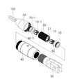
도 1은 본 발명의 제1실시예에 따른 쌍방향 웨지 케이블 정착장치의 분리사시도.
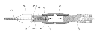
도 2는 도 1에 도시된 쌍방향 웨지 케이블 정착장치의 결합 단면도.
도 3은 쌍방향 웨지를 이용한 웨지 이탈을 방지하는 방법을 설명하기 위한 도면.
도 4 및 도 5는 도 1에 도시된 쌍방향 웨지 케이블 정착장치를 이용하여 케이블 인장력을 도입하는 방법을 설명하기 위한 도면.
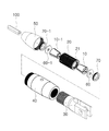
도 6은 본 발명의 제2실시예에 따른 쌍방향 웨지 케이블 정착장치의 분리 사시도.
도 7은 본 발명의 제3실시예에 따른 쌍방향 웨지 케이블 정착장치의 분리 사시도이다.1 is an exploded perspective view of a bidirectional wedge cable fixing apparatus according to a first embodiment of the present invention;
Fig. 2 is an assembled cross-sectional view of the bidirectional wedge cable fixing apparatus shown in Fig. 1. Fig.
Fig. 3 is a view for explaining a method for preventing wedge deviation using a bidirectional wedge; Fig.
Figs. 4 and 5 are diagrams for explaining a method of introducing a cable tensile force using the bidirectional wedge cable fixing apparatus shown in Fig. 1; Fig.
6 is an exploded perspective view of a bidirectional wedge cable fixing apparatus according to a second embodiment of the present invention;
7 is an exploded perspective view of a bidirectional wedge cable fixing apparatus according to a third embodiment of the present invention.
이하에서는 도면을 참조하면서 본 발명의 제1실시예에 대하여 설명함으로써 본 발명을 실시하기 위한 구체적인 내용을 설명하기로 한다.DETAILED DESCRIPTION OF THE PREFERRED EMBODIMENTS Hereinafter, a first embodiment of the present invention will be described with reference to the accompanying drawings.
도 1은 본 발명의 제1실시예에 따른 쌍방향 웨지 케이블 정착장치의 분리 사시도, 도 2는 도 1에 도시된 쌍방향 웨지 케이블 정착장치의 결합 단면도, 도 3은 쌍방향 웨지를 이용한 웨지 이탈을 제어하는 방법을 설명하기 위한 도면, 도 4 및 도 5는 도 1에 도시된 쌍방향 웨지 케이블 정착장치를 이용하여 케이블 인장력을 도입하는 방법을 설명하기 위한 도면이다.FIG. 1 is an exploded perspective view of a bidirectional wedge cable fixing apparatus according to a first embodiment of the present invention, FIG. 2 is an assembled cross-sectional view of the bidirectional wedge cable fixing apparatus shown in FIG. 1, Figs. 4 and 5 are views for explaining a method of introducing a cable tensile force using the bidirectional wedge cable fixing apparatus shown in Fig. 1. Fig.
본 제1실시예에 따른 쌍방향 웨지 케이블 정착장치는 웨지(10, 10-1), 웨지블록(20), 정착블록(30), 길이조절블록(40), 케이싱(50), 고무패킹(60), 밀폐압력블록(70), 케이블(100)로 구성된다.The bidirectional wedge cable fixing apparatus according to the first embodiment includes
상기 웨지(10, 10-1)는 그 내주면이 고정되는 케이블(100)의 단부 외주면을 감싸 웨지(10)의 내주면과 케이블(100)의 외주면과 접촉면의 마찰력에 의해서 케이블(100)을 정착하기 위한 수단으로 일반적으로 두 개에서 네 개의 절편으로 이루어지며, 웨지(10, 10-1)의 형상은 도 2의 단면도에서 도시된 바와 같이 축선 방향으로 갈수록 외경이 줄어 들도록 테이퍼져 있다.The
상기 웨지블록(20)은 상기 웨지(10, 10-1)와 케이블(100)이 맞물린 상태로 고정하기 위한 것으로서 상기 웨지블록(20) 내주면과 상기 웨지(10, 10-1)의 외주면이 맞닿도록 구성된다. 상기 웨지블록(20)에도 상기 웨지(10, 10-1)의 외주면에 형성된 테이퍼와 동일한 각으로 테이퍼가 마련된 구멍이 구비되어, 상기 케이블(100)이 상기 웨지(10, 10-1)에 수용된 상태로 웨지(10, 10-1)가 웨지블록(20)의 구멍에 맞물린 상태로 고정된다.The
상기 웨지블록(20)과 상기 웨지(10)는 일반적으로 일단부에서만 고정을 하지만, 본 발명은 도 3에서 도시한 바와 같이 테이퍼진 웨지(10, 10-1)를 서로 다른 방향으로 웨지블록(20)의 양단부에 고정하여 구조물의 진동으로 인한 웨지(10, 10-1)의 이탈을 방지할 수 있다. 구조물의 케이블(100)은 영구적으로 작용하는 인장하중 방향을 고정하는 웨지(10)와 구조물 진동시 웨지 이탈 방지를 하기 위하여 고정하는 웨지(10-1)로 양단부에서 고정하여 케이블 정착이 분리될 가능성을 배제 시킨다.Although the
한편, 공장 제작된 케이블(100)은 실제 시공된 현장 적용시 케이블 길이 오차가 발생하지만, 본 발명은 실제 시공된 현장에서 측량한 길이를 바탕으로 절단하여 간단한 장비로 신속하게 웨지(10, 10-1) 정착이 가능하여 케이블의 길이 오차가 발생하지 않는다.However, the present invention is based on the fact that the length of the
상기 정착블록(30)은 그 일단부가 상기 케이블(100)을 구조물과 연결시키는 역할을 한다. 상기 정착블록(30)은 핀으로 고정된 힌지 형태로 이루어져 변위는 허용하지 않지만 일방향 회전은 허용되며, 일단부는 구조물과 핀으로 연결되고 타단부는 상기 길이조절블록(40)과 나사 연결된다.One end of the
상기 길이조절블록(40)은 도 1에 도시된 바와 같이 전체적으로 중공부를 가지며 파이프 형태나 다각형 형태를 가질 수 있다. 상기 길이조절블록(40)은 양단부의 나사홈 방향이 반대방향으로 일단부는 상기 웨지블록(20)과 타단부는 상기 정착블록(30)과 상대회전이 가능하도록 결합된다. 이러한 구성에 의해서 상기 길이조절블록(40)을 회전시킴으로써 정착블록(30)을 기준으로 가까운 방향으로 이동 할 수 있고, 멀어지는 방향으로 이동할 수도 있다.As shown in FIG. 1, the
정착블록(30)과 웨지블록(20)의 상대회전이동이 가능한 매커니즘에 의해 케이블(100)에 인장력을 도입할 수 있다.A tensile force can be introduced to the
상기 케이싱(50)은 웨지(10) 및 케이블(100), 웨지블록(20)에 강수등의 물이 유입되지 않도록 하는 역할을 수행한다.The
상기 밀폐압력블록(70)과 상기 고무패킹(60)은 웨지블록(20)의 내주면을 밀폐하여 웨지블록(20) 내주면과 웨지(10)의 부식방지 역할을 수행한다.The
이하에서는 도 2 내지 도 5를 참조하면서 설명된 실시예에 따른 쌍방향 웨지케이블 정착장치를 이용하여 케이블에 인장력을 도입하는 방법에 대하여 설명함으로써 각 구성요소에 대한 기능 및 효과에 대하여 설명하기로 한다.Hereinafter, a method of introducing a tensile force to a cable using the bidirectional wedge cable fixing apparatus according to the embodiment described with reference to FIGS. 2 to 5 will be described, and the functions and effects of each component will be described.
우선 도 3에 도시된 바와 같이 케이블(100)과 웨지(10, 10-1)를 웨지블록(20)의 양단부에 서로 반대 방향으로 결합하고 고무패킹(60)과 밀폐압력블록(70)을 체결한다. 전술한 바와같이 웨지(10, 10-1)의 이탈은 케이블의 인장하중이 가해지는 방향과 반대방향으로 하중이 가해졌을 때 발생하는데 본 발명은 웨지블록(20)의 양단부에 테이퍼가 서로 반대 방향이 되도록 각각의 웨지(10, 10-1)를 정착하는 것에 의하여 케이블(100)과 웨지블록(20)은 분리될 가능성이 없이 정착블록(30)에 정착하게 된다.3, the
도 4에 도시된 바와같이 양단부에 웨지(10)가 정착된 웨지블록(20)과 정착블록(20)을 길이조절블록(40)에 나사 결합한 상태에서 인장력을 가한다. 이때 케이싱(50)은 케이블(100)의 중앙부로 이동시킨다.A tensile force is applied in a state where the
케이블(100)에 인장력을 가하게 되면 길이조절블록(40)과 웨지블록(20) 및 길이조절블록(40)과 정착블록(30)과의 나사홈의 간격이동으로 간단한 장비를 이용한 길이조절블록(40)의 회전이 가능하여 일방향으로 회전시키면 도 4에 도시한 바와 같이 웨지블록(20)과 정착블록(30) 사이의 거리가 좁혀지게 된다. 케이블(100)의 길이는 곧 인장하중으로 길이 조정으로 인장력이 도입된다.The
상기 서술한 바와 같은 방법으로 케이블에 추가적인 인장력 도입 및 인장력을 일부제거 할 수 있는데 길이조절블록(40) 내부에 나사선이 체결되지 않은 여유 길이 만큼 추가 인장력을 도입할 수 있으며, 반대로 인장력을 일부 제거할 필요가 있을 경우 인장력 재하시와 유사한 방법으로 도 5에 도시한 바와 같이 길이조절블록(40)의 회전 방향만 반대로 하면 나사결합길이가 더 짧아지면서 웨지블록(20)과 정착블록(30) 사이의 거리가 멀어지며 인장력을 일부 제거할 수 있다.It is possible to introduce an additional tensile force into the cable and partially remove the tensile force in the same manner as described above. In this case, an additional tensile force can be introduced into the
이와 유사하게, 도 6에 도시된 본 발명의 제2실시예에 따른 쌍방향 웨지 케이블 정착장치는 상기 케이블(100)이 복수로 배치되는 경우 웨지블록(20)에 중공부(21)도 복수로 마련하여 케이블(100) 복수가 개별 웨지로 정착된다.Similarly, in the bidirectional wedge cable fixing apparatus according to the second embodiment of the present invention shown in Fig. 6, when a plurality of the
한편, 도 7에 도시된 본 발명의 제3실시예에 따른 쌍방향 웨지 케이블 정착장치는 상기 케이블(100)이 복수로 배치되는 경우 웨지블록(20)에 중공부(21)는 단수로 마련하여 복수의 케이블(100)을 단수의 웨지(10)로 일괄 정착된다.7, in a bidirectional wedge cable fixing apparatus according to a third embodiment of the present invention, when a plurality of the
이상에서 본 발명의 바람직한 하나의 실시예에 대하여 설명함으로써 본 발명을 실시하기 위한 구체적인 내용을 제공하였다. 주지하는 바와 같이 특허의 보호범위는 청구항에 기재된 사항에 의해 기재되는데, 본 발명의 청구항에 기재된 기술적 사상이 설명된 실시예에 한정되는 것은 아니며 본 발명의 기술적 사상의 범위 안에서 다양한 형태의 쌍방향웨지 케이블 고정장치로 구체화될 수 있다.Hereinafter, a preferred embodiment of the present invention will be described, thereby providing specific details for carrying out the present invention. As is well known, the protection scope of the patent is described by the matters described in the claims, and the technical idea described in the claims of the present invention is not limited to the described embodiments, but various types of bidirectional wedge cables May be embodied as a locking device.
10 : 웨지 20 : 웨지블록
30 : 정착블록 40 : 길이조절블록
50 : 케이싱 60 : 고무패킹
70 : 밀폐압력블록 100 : 케이블10: Wedge 20: Wedge block
30: Fixing block 40: Length adjusting block
50: Casing 60: Rubber packing
70: Sealing pressure block 100: Cable
Claims (6)
테이퍼가 형성된 제1구멍과, 상기 케이블의 축선 방향으로 상기 제1구멍과 연통되면서 상기 제1구멍의 테이퍼와는 정 반대의 방향의 테이퍼가 마련된 제2구멍이 각각 양단에 형성된 웨지 블록과;
상기 제1구멍의 테이퍼와 동일한 각의 테이퍼가 외주면에 형성되고, 다수의 절편으로 형성되며, 내주면에 상기 케이블을 수용한 상태로 상기 제1구멍에 결합되는 제1웨지와;
상기 제2구멍의 테이퍼와 동일한 각의 테이퍼가 외주면에 형성되고, 다수의 절편으로 형성되며, 내주면에 상기 케이블을 수용한 상태로 상기 제2구멍에 결합되어, 상기 제1웨지와는 반대 방향으로 배치되는 제2웨지를;
포함하여 구성된 것을 특징으로 하는 케이블의 쌍방향 정착 장치.
A bidirectional fixing device for a cable fixing the cable in two directions,
A wedge block having a first hole having a tapered portion and a second hole communicating with the first hole in an axial direction of the cable and having a taper in a direction opposite to a taper of the first hole;
A first wedge formed on an outer circumferential surface of the taper having the same angle as that of the taper of the first hole, the first wedge being formed of a plurality of segments and coupled to the first hole while accommodating the cable in an inner circumferential surface thereof;
A taper of the same angle as that of the taper of the second hole is formed on the outer circumferential surface and is formed of a plurality of segments and is coupled to the second hole in a state of accommodating the cable on the inner circumferential surface, A second wedge disposed;
Wherein the first and second fixing members are disposed on the first and second fixing units.
상기 케이블이 설치되는 구조물에 일단부가 고정되고, 상기 웨지 블록과도 연결된 정착블록을;
더 포함하여 구성된 것을 특징으로 하는 케이블의 쌍방향 정착 장치.
The method according to claim 1,
A fixation block fixed at one end to a structure in which the cable is installed and connected to the wedge block;
Further comprising: a fixing unit for fixing the cable to the fixing unit.
상기 케이블이 설치되는 구조물에 일단부가 고정된 정착블록과;
상기 정착 블록과 일단부에서 나사 결합되고, 상기 웨지 블록과 타단부에서 나사 결합되고, 나사 결합되는 길이가 조절 가능한 길이조절블록과;
상기 길이조절블록의 외주면을 감싸는 케이싱을;
더 포함하여 구성된 것을 특징으로 하는 케이블의 쌍방향 정착 장치.
The method according to claim 1,
A fixing block having one end fixed to a structure in which the cable is installed;
A length adjustable block screwed at one end with the fixation block and screwed at the other end with the wedge block;
A casing surrounding the outer circumference of the length adjusting block;
Further comprising: a fixing unit for fixing the cable to the fixing unit.
상기 웨지 및 상기 웨지블록 내주면의 부식을 방지하기 위한 고무패킹, 밀폐압력블록이 더 구비되는 것을 특징으로 하는 쌍방향 웨지 케이블 정착장치.
The method according to claim 1,
And a rubber packing for preventing corrosion of the wedge and the inner circumferential surface of the wedge block, and a hermetic pressure block.
상기 케이블이 복수로 배치되는 경우 상기 웨지블록에 중공부도 복수로 마련하여 복수의 케이블이 개별 웨지로 정착되는 것을 특징으로 하는 쌍방향 웨지 케이블 정착장치.
The method according to claim 1,
Wherein a plurality of hollow portions are provided in the wedge block so that a plurality of cables are fixed to individual wedges when the cables are arranged in plural.
상기 케이블이 복수로 배치되는 경우 상기 웨지블록에 중공부는 단수로 마련하여 복수 케이블을 단수의 웨지로 일괄 정착되는 것을 특징으로 하는 쌍방향 웨지 케이블 정착장치.The method according to claim 1,
Wherein when the cables are arranged in plural, the hollow portion is provided in the wedge block in a single number so that a plurality of cables are integrally fixed by a single number of wedges.
Priority Applications (1)
| Application Number | Priority Date | Filing Date | Title |
|---|---|---|---|
| KR1020140061924A KR101423905B1 (en) | 2014-05-23 | 2014-05-23 | Cable anchorange system in two ways |
Applications Claiming Priority (1)
| Application Number | Priority Date | Filing Date | Title |
|---|---|---|---|
| KR1020140061924A KR101423905B1 (en) | 2014-05-23 | 2014-05-23 | Cable anchorange system in two ways |
Related Parent Applications (1)
| Application Number | Title | Priority Date | Filing Date |
|---|---|---|---|
| KR1020120096470A Division KR20140029945A (en) | 2012-08-31 | 2012-08-31 | Cable anchorange system using interactive wedge |
Publications (2)
| Publication Number | Publication Date |
|---|---|
| KR20140077875A true KR20140077875A (en) | 2014-06-24 |
| KR101423905B1 KR101423905B1 (en) | 2014-08-13 |
Family
ID=51129678
Family Applications (1)
| Application Number | Title | Priority Date | Filing Date |
|---|---|---|---|
| KR1020140061924A Active KR101423905B1 (en) | 2014-05-23 | 2014-05-23 | Cable anchorange system in two ways |
Country Status (1)
| Country | Link |
|---|---|
| KR (1) | KR101423905B1 (en) |
Cited By (1)
| Publication number | Priority date | Publication date | Assignee | Title |
|---|---|---|---|---|
| CN111155418A (en) * | 2020-01-15 | 2020-05-15 | 东南大学 | A kind of anti-falling beam device and method using prefabricated bridge suspension point structure |
Family Cites Families (3)
| Publication number | Priority date | Publication date | Assignee | Title |
|---|---|---|---|---|
| KR200398519Y1 (en) * | 2005-07-29 | 2005-10-12 | 김정한 | A removal ground anchor |
| KR100956799B1 (en) * | 2008-04-29 | 2010-05-07 | 이상철 | Wedge steel wire clamp |
| KR100936082B1 (en) | 2009-04-28 | 2010-01-12 | 케이블텍 주식회사 | Apparatus for fixing cable |
-
2014
- 2014-05-23 KR KR1020140061924A patent/KR101423905B1/en active Active
Cited By (2)
| Publication number | Priority date | Publication date | Assignee | Title |
|---|---|---|---|---|
| CN111155418A (en) * | 2020-01-15 | 2020-05-15 | 东南大学 | A kind of anti-falling beam device and method using prefabricated bridge suspension point structure |
| CN111155418B (en) * | 2020-01-15 | 2021-08-06 | 东南大学 | A kind of anti-falling beam device and method using prefabricated bridge suspension point structure |
Also Published As
| Publication number | Publication date |
|---|---|
| KR101423905B1 (en) | 2014-08-13 |
Similar Documents
| Publication | Publication Date | Title |
|---|---|---|
| KR100936082B1 (en) | Apparatus for fixing cable | |
| US10655358B2 (en) | Barrier cable anchor | |
| US8220839B2 (en) | Pipe insert | |
| ES2941694T3 (en) | Cable anchorage with sealing element and prestressing system comprising said anchorage | |
| US9982494B2 (en) | Device arranged for attaching a pipe stem on a tubular body | |
| JP7583380B2 (en) | Fittings | |
| US9780548B1 (en) | Tandem trunnion clamp | |
| JP2018526549A (en) | Cable mooring system | |
| JP2008224635A (en) | Fixing jig for optical fiber cable sensor measuring device | |
| CN105209698A (en) | Aseismic connection device for connecting a panel to a beam | |
| KR101423905B1 (en) | Cable anchorange system in two ways | |
| CN109989720A (en) | A kind of universal pole plate telescoping ram | |
| KR20140029945A (en) | Cable anchorange system using interactive wedge | |
| KR100591896B1 (en) | Cable tensioner | |
| KR100936081B1 (en) | Apparatus for fixing cable | |
| JP2008285931A (en) | Height adjusting device for bearing | |
| RU2019124626A (en) | BREAKABLE NUT WITH FAILURE SURFACE WITH A LARGE ANGLE | |
| JP6218834B2 (en) | Anchor bolt | |
| KR101386419B1 (en) | Apparatus for fixing cable | |
| KR20110096738A (en) | Cable tension control device | |
| KR102006924B1 (en) | Apparatus for connecting pipes | |
| KR102126973B1 (en) | Device of wedge installation | |
| KR200416815Y1 (en) | Cable tensioner | |
| KR102242094B1 (en) | Sensor module with attachment means | |
| CN106352019A (en) | Adjustable large-angle inhaul cable positioner and method for locating inhaul cable through same |
Legal Events
| Date | Code | Title | Description |
|---|---|---|---|
| A107 | Divisional application of patent | ||
| A201 | Request for examination | ||
| PA0107 | Divisional application |
St.27 status event code: A-0-1-A10-A18-div-PA0107 St.27 status event code: A-0-1-A10-A16-div-PA0107 |
|
| PA0201 | Request for examination |
St.27 status event code: A-1-2-D10-D11-exm-PA0201 |
|
| R18-X000 | Changes to party contact information recorded |
St.27 status event code: A-3-3-R10-R18-oth-X000 |
|
| E701 | Decision to grant or registration of patent right | ||
| PE0701 | Decision of registration |
St.27 status event code: A-1-2-D10-D22-exm-PE0701 |
|
| PG1501 | Laying open of application |
St.27 status event code: A-1-1-Q10-Q12-nap-PG1501 |
|
| GRNT | Written decision to grant | ||
| PR0701 | Registration of establishment |
St.27 status event code: A-2-4-F10-F11-exm-PR0701 |
|
| PR1002 | Payment of registration fee |
St.27 status event code: A-2-2-U10-U11-oth-PR1002 Fee payment year number: 1 |
|
| PG1601 | Publication of registration |
St.27 status event code: A-4-4-Q10-Q13-nap-PG1601 |
|
| R18-X000 | Changes to party contact information recorded |
St.27 status event code: A-5-5-R10-R18-oth-X000 |
|
| PN2301 | Change of applicant |
St.27 status event code: A-5-5-R10-R11-asn-PN2301 |
|
| PN2301 | Change of applicant |
St.27 status event code: A-5-5-R10-R14-asn-PN2301 |
|
| R18-X000 | Changes to party contact information recorded |
St.27 status event code: A-5-5-R10-R18-oth-X000 |
|
| R18-X000 | Changes to party contact information recorded |
St.27 status event code: A-5-5-R10-R18-oth-X000 |
|
| P22-X000 | Classification modified |
St.27 status event code: A-4-4-P10-P22-nap-X000 |
|
| PN2301 | Change of applicant |
St.27 status event code: A-5-5-R10-R11-asn-PN2301 |
|
| P14-X000 | Amendment of ip right document requested |
St.27 status event code: A-5-5-P10-P14-nap-X000 |
|
| PN2301 | Change of applicant |
St.27 status event code: A-5-5-R10-R14-asn-PN2301 |
|
| FPAY | Annual fee payment |
Payment date: 20170628 Year of fee payment: 4 |
|
| PR1001 | Payment of annual fee |
St.27 status event code: A-4-4-U10-U11-oth-PR1001 Fee payment year number: 4 |
|
| R18-X000 | Changes to party contact information recorded |
St.27 status event code: A-5-5-R10-R18-oth-X000 |
|
| FPAY | Annual fee payment |
Payment date: 20180702 Year of fee payment: 5 |
|
| PR1001 | Payment of annual fee |
St.27 status event code: A-4-4-U10-U11-oth-PR1001 Fee payment year number: 5 |
|
| PN2301 | Change of applicant |
St.27 status event code: A-5-5-R10-R11-asn-PN2301 |
|
| PN2301 | Change of applicant |
St.27 status event code: A-5-5-R10-R14-asn-PN2301 |
|
| R18-X000 | Changes to party contact information recorded |
St.27 status event code: A-5-5-R10-R18-oth-X000 |
|
| R18-X000 | Changes to party contact information recorded |
St.27 status event code: A-5-5-R10-R18-oth-X000 |
|
| FPAY | Annual fee payment |
Payment date: 20190703 Year of fee payment: 6 |
|
| PR1001 | Payment of annual fee |
St.27 status event code: A-4-4-U10-U11-oth-PR1001 Fee payment year number: 6 |
|
| S17-X000 | Non-exclusive voluntary license recorded |
St.27 status event code: A-4-4-S10-S17-lic-X000 |
|
| PN2301 | Change of applicant |
St.27 status event code: A-5-5-R10-R11-asn-PN2301 |
|
| PN2301 | Change of applicant |
St.27 status event code: A-5-5-R10-R14-asn-PN2301 |
|
| P14-X000 | Amendment of ip right document requested |
St.27 status event code: A-5-5-P10-P14-nap-X000 |
|
| P14-X000 | Amendment of ip right document requested |
St.27 status event code: A-5-5-P10-P14-nap-X000 |
|
| P14-X000 | Amendment of ip right document requested |
St.27 status event code: A-5-5-P10-P14-nap-X000 |
|
| PR1001 | Payment of annual fee |
St.27 status event code: A-4-4-U10-U11-oth-PR1001 Fee payment year number: 7 |
|
| P14-X000 | Amendment of ip right document requested |
St.27 status event code: A-5-5-P10-P14-nap-X000 |
|
| PN2301 | Change of applicant |
St.27 status event code: A-5-5-R10-R11-asn-PN2301 |
|
| PN2301 | Change of applicant |
St.27 status event code: A-5-5-R10-R14-asn-PN2301 |
|
| P14-X000 | Amendment of ip right document requested |
St.27 status event code: A-5-5-P10-P14-nap-X000 |
|
| P14-X000 | Amendment of ip right document requested |
St.27 status event code: A-5-5-P10-P14-nap-X000 |
|
| PR1001 | Payment of annual fee |
St.27 status event code: A-4-4-U10-U11-oth-PR1001 Fee payment year number: 8 |
|
| R18-X000 | Changes to party contact information recorded |
St.27 status event code: A-5-5-R10-R18-oth-X000 |
|
| P14-X000 | Amendment of ip right document requested |
St.27 status event code: A-5-5-P10-P14-nap-X000 |
|
| P14-X000 | Amendment of ip right document requested |
St.27 status event code: A-5-5-P10-P14-nap-X000 |
|
| P14-X000 | Amendment of ip right document requested |
St.27 status event code: A-5-5-P10-P14-nap-X000 |
|
| P14-X000 | Amendment of ip right document requested |
St.27 status event code: A-5-5-P10-P14-nap-X000 |
|
| PR1001 | Payment of annual fee |
St.27 status event code: A-4-4-U10-U11-oth-PR1001 Fee payment year number: 9 |
|
| P14-X000 | Amendment of ip right document requested |
St.27 status event code: A-5-5-P10-P14-nap-X000 |
|
| R18-X000 | Changes to party contact information recorded |
St.27 status event code: A-5-5-R10-R18-oth-X000 |
|
| P14-X000 | Amendment of ip right document requested |
St.27 status event code: A-5-5-P10-P14-nap-X000 |
|
| P14-X000 | Amendment of ip right document requested |
St.27 status event code: A-5-5-P10-P14-nap-X000 |
|
| PN2301 | Change of applicant |
St.27 status event code: A-5-5-R10-R11-asn-PN2301 |
|
| PN2301 | Change of applicant |
St.27 status event code: A-5-5-R10-R14-asn-PN2301 |
|
| P14-X000 | Amendment of ip right document requested |
St.27 status event code: A-5-5-P10-P14-nap-X000 |
|
| P14-X000 | Amendment of ip right document requested |
St.27 status event code: A-5-5-P10-P14-nap-X000 |
|
| P14-X000 | Amendment of ip right document requested |
St.27 status event code: A-5-5-P10-P14-nap-X000 |
|
| P14-X000 | Amendment of ip right document requested |
St.27 status event code: A-5-5-P10-P14-nap-X000 |
|
| P14-X000 | Amendment of ip right document requested |
St.27 status event code: A-5-5-P10-P14-nap-X000 |
|
| PR1001 | Payment of annual fee |
St.27 status event code: A-4-4-U10-U11-oth-PR1001 Fee payment year number: 10 |
|
| P14-X000 | Amendment of ip right document requested |
St.27 status event code: A-5-5-P10-P14-nap-X000 |
|
| P14-X000 | Amendment of ip right document requested |
St.27 status event code: A-5-5-P10-P14-nap-X000 |
|
| P14-X000 | Amendment of ip right document requested |
St.27 status event code: A-5-5-P10-P14-nap-X000 |
|
| P14-X000 | Amendment of ip right document requested |
St.27 status event code: A-5-5-P10-P14-nap-X000 |
|
| P14-X000 | Amendment of ip right document requested |
St.27 status event code: A-5-5-P10-P14-nap-X000 |
|
| P14-X000 | Amendment of ip right document requested |
St.27 status event code: A-5-5-P10-P14-nap-X000 |
|
| P14-X000 | Amendment of ip right document requested |
St.27 status event code: A-5-5-P10-P14-nap-X000 |
|
| P14-X000 | Amendment of ip right document requested |
St.27 status event code: A-5-5-P10-P14-nap-X000 |
|
| P14-X000 | Amendment of ip right document requested |
St.27 status event code: A-5-5-P10-P14-nap-X000 |
|
| R18-X000 | Changes to party contact information recorded |
St.27 status event code: A-5-5-R10-R18-oth-X000 |
|
| P14-X000 | Amendment of ip right document requested |
St.27 status event code: A-5-5-P10-P14-nap-X000 |
|
| P14-X000 | Amendment of ip right document requested |
St.27 status event code: A-5-5-P10-P14-nap-X000 |
|
| P14-X000 | Amendment of ip right document requested |
St.27 status event code: A-5-5-P10-P14-nap-X000 |
|
| PR1001 | Payment of annual fee |
St.27 status event code: A-4-4-U10-U11-oth-PR1001 Fee payment year number: 11 |
|
| P14-X000 | Amendment of ip right document requested |
St.27 status event code: A-5-5-P10-P14-nap-X000 |
|
| P14-X000 | Amendment of ip right document requested |
St.27 status event code: A-5-5-P10-P14-nap-X000 |
|
| P14-X000 | Amendment of ip right document requested |
St.27 status event code: A-5-5-P10-P14-nap-X000 |
|
| P14-X000 | Amendment of ip right document requested |
St.27 status event code: A-5-5-P10-P14-nap-X000 |
|
| P14-X000 | Amendment of ip right document requested |
St.27 status event code: A-5-5-P10-P14-nap-X000 |
|
| PR1001 | Payment of annual fee |
St.27 status event code: A-4-4-U10-U11-oth-PR1001 Fee payment year number: 12 |
|
| R18 | Changes to party contact information recorded |
Free format text: ST27 STATUS EVENT CODE: A-5-5-R10-R18-OTH-X000 (AS PROVIDED BY THE NATIONAL OFFICE) |
|
| R18-X000 | Changes to party contact information recorded |
St.27 status event code: A-5-5-R10-R18-oth-X000 |
|
| P14 | Amendment of ip right document requested |
Free format text: ST27 STATUS EVENT CODE: A-5-5-P10-P14-NAP-X000 (AS PROVIDED BY THE NATIONAL OFFICE) |
|
| P14-X000 | Amendment of ip right document requested |
St.27 status event code: A-5-5-P10-P14-nap-X000 |
|
| PR1001 | Payment of annual fee |
St.27 status event code: A-4-4-U10-U11-oth-PR1001 Fee payment year number: 13 |
|
| U11 | Full renewal or maintenance fee paid |
Free format text: ST27 STATUS EVENT CODE: A-4-4-U10-U11-OTH-PR1001 (AS PROVIDED BY THE NATIONAL OFFICE) Year of fee payment: 13 |