KR20140077882A - Device for changing pitch of stacked objects - Google Patents
Device for changing pitch of stacked objects Download PDFInfo
- Publication number
- KR20140077882A KR20140077882A KR1020147005758A KR20147005758A KR20140077882A KR 20140077882 A KR20140077882 A KR 20140077882A KR 1020147005758 A KR1020147005758 A KR 1020147005758A KR 20147005758 A KR20147005758 A KR 20147005758A KR 20140077882 A KR20140077882 A KR 20140077882A
- Authority
- KR
- South Korea
- Prior art keywords
- pitch
- base plate
- spring
- base plates
- work
- Prior art date
- Legal status (The legal status is an assumption and is not a legal conclusion. Google has not performed a legal analysis and makes no representation as to the accuracy of the status listed.)
- Ceased
Links
Images




Classifications
-
- H—ELECTRICITY
- H10—SEMICONDUCTOR DEVICES; ELECTRIC SOLID-STATE DEVICES NOT OTHERWISE PROVIDED FOR
- H10P—GENERIC PROCESSES OR APPARATUS FOR THE MANUFACTURE OR TREATMENT OF DEVICES COVERED BY CLASS H10
- H10P72/00—Handling or holding of wafers, substrates or devices during manufacture or treatment thereof
- H10P72/30—Handling or holding of wafers, substrates or devices during manufacture or treatment thereof for conveying, e.g. between different workstations
- H10P72/32—Handling or holding of wafers, substrates or devices during manufacture or treatment thereof for conveying, e.g. between different workstations between different workstations
- H10P72/3202—Mechanical details, e.g. rollers or belts
-
- B—PERFORMING OPERATIONS; TRANSPORTING
- B65—CONVEYING; PACKING; STORING; HANDLING THIN OR FILAMENTARY MATERIAL
- B65H—HANDLING THIN OR FILAMENTARY MATERIAL, e.g. SHEETS, WEBS, CABLES
- B65H39/00—Associating, collating, or gathering articles or webs
-
- H—ELECTRICITY
- H10—SEMICONDUCTOR DEVICES; ELECTRIC SOLID-STATE DEVICES NOT OTHERWISE PROVIDED FOR
- H10P—GENERIC PROCESSES OR APPARATUS FOR THE MANUFACTURE OR TREATMENT OF DEVICES COVERED BY CLASS H10
- H10P72/00—Handling or holding of wafers, substrates or devices during manufacture or treatment thereof
- H10P72/30—Handling or holding of wafers, substrates or devices during manufacture or treatment thereof for conveying, e.g. between different workstations
- H10P72/34—Handling or holding of wafers, substrates or devices during manufacture or treatment thereof for conveying, e.g. between different workstations the wafers being stored in a carrier, involving loading and unloading
- H10P72/3411—Handling or holding of wafers, substrates or devices during manufacture or treatment thereof for conveying, e.g. between different workstations the wafers being stored in a carrier, involving loading and unloading involving loading and unloading of wafers
- H10P72/3412—Batch transfer of wafers
-
- H—ELECTRICITY
- H10—SEMICONDUCTOR DEVICES; ELECTRIC SOLID-STATE DEVICES NOT OTHERWISE PROVIDED FOR
- H10P—GENERIC PROCESSES OR APPARATUS FOR THE MANUFACTURE OR TREATMENT OF DEVICES COVERED BY CLASS H10
- H10P72/00—Handling or holding of wafers, substrates or devices during manufacture or treatment thereof
- H10P72/50—Handling or holding of wafers, substrates or devices during manufacture or treatment thereof for positioning, orientation or alignment
-
- H—ELECTRICITY
- H10—SEMICONDUCTOR DEVICES; ELECTRIC SOLID-STATE DEVICES NOT OTHERWISE PROVIDED FOR
- H10P—GENERIC PROCESSES OR APPARATUS FOR THE MANUFACTURE OR TREATMENT OF DEVICES COVERED BY CLASS H10
- H10P72/00—Handling or holding of wafers, substrates or devices during manufacture or treatment thereof
- H10P72/70—Handling or holding of wafers, substrates or devices during manufacture or treatment thereof for supporting or gripping
- H10P72/78—Handling or holding of wafers, substrates or devices during manufacture or treatment thereof for supporting or gripping using vacuum or suction, e.g. Bernoulli chucks
-
- B—PERFORMING OPERATIONS; TRANSPORTING
- B65—CONVEYING; PACKING; STORING; HANDLING THIN OR FILAMENTARY MATERIAL
- B65H—HANDLING THIN OR FILAMENTARY MATERIAL, e.g. SHEETS, WEBS, CABLES
- B65H2801/00—Application field
- B65H2801/87—Photovoltaic element manufacture, e.g. solar panels
Landscapes
- Manipulator (AREA)
- Sheets, Magazines, And Separation Thereof (AREA)
Abstract
하나의 피치로 하나의 용기에 적층되어 있는 적층물을 다른 피치로 변경하고 다른 용기에 적층 형상으로 수납하는 작업을 효율적으로 행하는 것.
베이스 플레이트(3)에 소정의 피치로 적층 형상으로 나란히 배치된 다수의 워크(51)를 흡착하는 흡착 패드(25)가 설치된다. 베이스 플레이트에 구동축(31)에 연동하는 가변 스페이서(17)의 회전에 의해 베이스 플레이트 간의 피치가 가변으로 된다. 이때 1군의 베이스 플레이트와의 사이에 흡착 패드에 연통하는 기밀의 연통로(28)가 형성된다. 연통로(28)는 인접하는 베이스 플레이트의 통과구멍 사이에 신축 자유로운 탄성 패킹(15)이 연이어 설치됨으로써 형성된다. 탄성 패킹, 가변 스페이서는 베이스 플레이트에 연동하여 이동한다. 베이스 플레이트에는 베이스 플레이트 간의 피치의 고정을 해제하기 위한 스프링(9)이 설치된다. 가변 스페이서(17)는 원주면 위에서 두께가 상이한 부분이 형성되어 있다. The laminate which is laminated in one container at one pitch is changed to another pitch, and the work of efficiently stacking the laminate in another container is performed.
There is provided an adsorption pad 25 for adsorbing a plurality of workpieces 51 arranged side by side in a laminated form at a predetermined pitch on the base plate 3. [ The pitch between the base plates is made variable by the rotation of the variable spacer 17 interlocked with the drive shaft 31 on the base plate. At this time, an airtight communication passage (28) communicating with the adsorption pad is formed between the base plate and the group of the first group. The communication path (28) is formed by providing an elastic packing (15) stretched freely between the passing holes of the adjacent base plates. The elastic packing and the variable spacer move in conjunction with the base plate. The base plate is provided with a spring (9) for releasing the fixing of the pitch between the base plates. The variable spacer 17 has a portion having a thickness different from that of the circumferential surface.
Description
본원 발명은 다수의 얇은 두께의 워크가 소정의 피치로 적층 형상으로 나란히 배치되어 있는 경우의 워크 간 피치를 변경하는 장치에 관한 것이다. The present invention relates to an apparatus for changing the pitch between workpieces when a plurality of thin-walled workpieces are arranged side by side in a laminated shape at a predetermined pitch.
예를 들면, 솔라 패널과 같은 셀이라고 불리는 얇은 두께의 이송 대상물(이하, 「워크」라고 함)을 하나의 용기로부터 다른 용기로 옮기는 경우, 생산 공정상의 이유로, 적층 형상으로 나란히 배치되는 워크 간의 피치가 상이할 때가 있다. For example, in the case of transferring a thin transport object (hereinafter referred to as a " work ") called a cell, such as a solar panel, from one container to another container, .
이러한 경우, 종래는 사람 손으로 한장 한장 상이한 피치의 용기로 옮기고 있었다. 그렇지만, 이러한 대응으로는 효율이 매우 나쁘다. 그것뿐만 아니라, 예를 들면, 솔라 패널과 같은 얇은 두께의 워크에서는, 경사 방향에 예측하지 못한 외력이 걸리면 워크가 용이하게 손상된다고 하는 문제가 있었다. In this case, conventionally, human hands have been transferred to containers of different pitches one by one. However, the efficiency is very bad with this countermeasure. In addition, there has been a problem in that, for example, in the case of a thin-walled work such as a solar panel, if an unexpected external force is applied in the oblique direction, the work is easily damaged.
또한 로봇에 의해 상기 옮김을 행하는 경우에는 이러한 예측하지 못한 힘이 걸리는 것을 방지할 수 있지만, 역시 한장 한장 옮기므로 효율을 높일 수 없다. In addition, in the case of carrying out the transfer by the robot, it is possible to prevent such unpredictable force from being applied, but the efficiency can not be increased because it is also transferred one by one.
본원 발명은 상기 워크의 적층 상태를 유지한 채 적층 피치만 변경하는 장치이다. 이러한 장치에 관하여, 국제특허분류「B65H 3/00」에서「피치」,「흡착」,「가변」에 관한 기술을 조사해 보았지만, 의미있는 정보를 발견할 수 없었다. 또한, 참고 정보는 다음과 같다. The present invention is an apparatus for changing only the lamination pitch while maintaining the lamination state of the work. With respect to such a device, although the technology relating to "pitch", "adsorption", "variable" was examined in the international patent classification "
(발명의 개요)(Summary of the Invention)
(발명이 해결하고자 하는 과제)(Problems to be Solved by the Invention)
본원 발명은 상기 결점을 해소하고, 하나의 피치(예를 들면, 작은 피치)로 하나의 용기에 적층되어 있는 적층물을, 다른 피치(예를 들면, 큰 피치)로 변경하고 다른 용기에 적층 형상으로 수납하는 작업을 효율적으로 행하는 것을 목적으로 한다. The present invention solves the above drawbacks and can be achieved by changing the laminate stacked in one container to one pitch (for example, a small pitch) to another pitch (for example, a large pitch) In order to efficiently carry out the work of storing the product.
또한 상기 옮김 작업을 확실하고, 안정적이고, 원활하게 행하는 것을 목적으로 한다. It is another object of the present invention to carry out the transfer operation reliably, stably, and smoothly.
또한, 옮겨지는 워크가 이상 상태에 있는지 아닌지를 검출하는 것도 목적으로 한다. It is also intended to detect whether or not the transferred work is in an abnormal state.
상기 목적 달성을 위해, 본원 발명에 의한 적층물 피치 변경 장치는, 소정의 피치로 적층 형상으로 나란히 배치된 다수의 얇은 두께의 워크 간의 피치를 변경하는 장치로서, 이동 자유로운 가동 유지부와, 이 가동 유지부를 구동하는 구동부로 이루어지고, 상기 가동 유지부는 다수의 베이스 플레이트가 소정의 피치로 적층 형상으로 나란히 배치되어 이루어지고, 상기 각 베이스 플레이트에 상기 워크를 유지하는 동작 부재가 설치되고, 이 동작 부재는 연통로로부터 보내지는 구동 파워에 의해 작동되어 상기 워크를 각 개별로 유지하고, 상기 각 베이스 플레이트에 구동부의 구동축에 연동하는 회전 자유로운 가변 스페이서가 설치되고, 이 가변 스페이서의 회전에 의해 베이스 플레이트 간의 피치가 가변으로 되고, 또한 상기 각 베이스 플레이트에 상기 워크가 유지될 때, 1군의 베이스 플레이트와의 사이에 상기 동작 부재에 연통하는 기밀이며 신축 자유로운 연통로가 형성되는 것을 특징으로 한다. In order to achieve the above object, a laminate pitch changing device according to the present invention is an apparatus for changing the pitch between a plurality of thin-walled workpieces arranged side by side in a laminated shape at a predetermined pitch, the apparatus comprising: And a driving unit for driving the holding unit, wherein the movable holding unit includes a plurality of base plates arranged side by side at a predetermined pitch in a stacked manner, and each of the base plates is provided with an operating member for holding the work, Is rotatably supported by the driving shaft of the driving part and is provided with a rotatable variable spacer which is operated by the driving power sent from the communication path to keep the work individually, The pitch becomes variable, and the pitch of the phase When the workpiece is held, characterized in that between the base plate of the first group it is confidential and is formed by stretching the free communication of communicating with the operating member.
또한 청구항 1에 기재된 적층물 피치 변경 장치에 있어서, 상기 연통로는 인접하는 베이스 플레이트의 통과 구멍 사이에 신축 자유로운 탄성 패킹이 연이어 설치됨으로써 형성되는 것을 특징으로 한다. Further, in the laminate pitch changing device according to
또한 청구항 2에 기재된 적층물 피치 변경 장치에 있어서, 상기 각 탄성 패킹이 상기 각 베이스 플레이트에 연동하여 이동하는 것을 특징으로 한다. In the laminate pitch changing device according to the second aspect of the present invention, each of the elastic packing moves in conjunction with each of the base plates.
또한 청구항 1에 기재된 적층물 피치 변경 장치에 있어서, 상기 각 가변 스페이서가 상기 각 베이스 플레이트에 연동하여 이동하는 것을 특징으로 한다. Further, in the laminate pitch changing device according to
또한 청구항 1에 기재된 적층물 피치 변경 장치에 있어서, 상기 각 베이스 플레이트에 베이스 플레이트 간의 피치의 고정을 해제하기 위한 스프링이 설치되는 것을 특징으로 한다. Further, in the laminate pitch changing device according to
또한 청구항 2에 기재된 적층물 피치 변경 장치에 있어서, 상기 탄성 패킹은 벨로우즈 형상으로 형성되는 것을 특징으로 한다. Further, in the laminate pitch changing device according to claim 2, the elastic packing is formed in a bellows shape.
또한 청구항 1에 기재된 적층물 피치 변경 장치에 있어서, 상기 가변 스페이서는 원주면 상에서 두께가 상이한 부분이 형성되어 있고, 회전에 의해 상이한 두께의 부분이 상기 베이스 플레이트에 접함으로써 베이스 플레이트 간의 피치를 가변으로 하는 것을 특징으로 한다. Further, in the laminate pitch changing device according to
또한 청구항 5에 기재된 적층물 피치 변경 장치에 있어서, 상기 스프링은 축소된 상태의 베이스 플레이트를 복원시키는 힘에 대하여 고정된 베이스 플레이트측의 스프링력을 가동의 베이스 플레이트측의 스프링력보다 크게 형성하는 것을 특징으로 한다. Further, in the laminate pitch changing device according to
또한 청구항 8에 기재된 적층물 피치 변경 장치에 있어서, 상기 스프링의 스프링력을 베이스 플레이트의 소정의 개수마다 가동의 베이스 플레이트측을 향하여 계단 모양으로 작게 하는 것을 특징으로 한다. In the laminate pitch changing device according to
또한 청구항 8에 기재된 적층물 피치 변경 장치에 있어서, 상기 스프링의 스프링력을 가동의 베이스 플레이트측을 향하여 직선상으로 작게 하는 것을 특징으로 한다. In the laminate pitch changing device as set forth in
또한 청구항 5에 기재된 적층물 피치 변경 장치에 있어서, 상기 스프링이 단일개의 스프링으로 이루어지는 것을 특징으로 한다. In the laminate pitch changing device according to
또한 청구항 5에 기재된 적층물 피치 변경 장치에 있어서, 상기 스프링이 복수개의 스프링이 겹쳐져서 이루어지는 것을 특징으로 한다. Further, in the laminate pitch changing device according to
또한 청구항 1에 기재된 적층물 피치 변경 장치에 있어서, 상기 워크가 흡착될 때, 워크의 갈라짐, 깨짐 등 워크의 상태를 검출하는 검출부를 설치하는 것을 특징으로 한다. In the laminate pitch changing device according to
또한 청구항 13에 기재된 적층물 피치 변경 장치에 있어서, 상기 검출부는 상기 연통로의 출입구에 상기 연통로를 개폐하기 위해 설치되는 개폐 밸브와, 이 개폐 밸브에 설치되어 진공압 검출로에 연통되는 오리피스와, 이 진공압 검출로에 접속되는 센서로 이루어지고, 상기 구동 파워가 상기 연통로에 입력되어 상기 개폐 밸브를 닫은 후, 연통로 내의 압력 변화를 검출하는 것을 특징으로 한다. [0030] In the laminate pitch changing device according to
또한 청구항 1에 기재된 적층물 피치 변경 장치에 있어서, 상기 동작 부재가 상기 워크를 흡착하는 흡착 패드로 이루어지는 것을 특징으로 한다. Further, in the laminate pitch changing device according to
또한 청구항 1에 기재된 적층물 피치 변경 장치에 있어서, 상기 동작 부재가 상기 워크를 협착하는 협착 부재로 이루어지는 것을 특징으로 한다. Further, in the laminate pitch changing device according to
또한 청구항 1에 기재된 적층물 피치 변경 장치에 있어서, 1군의 베이스 플레이트는 소정의 개수마다 하나의 그룹으로 형성되는 것을 특징으로 한다. Further, in the laminate pitch changing device according to
또한 청구항 1에 기재된 적층물 피치 변경 장치에 있어서, 상기 각 베이스 플레이트에 동작 부재가 한 쌍 설치되고, 상기 각 베이스 플레이트에는 상기 가변 스페이서 및 이 동작 부재에 연통하는 상기 연통로가 한 쌍 설치되는 것을 특징으로 한다. In the laminate pitch changing device according to
또한 청구항 1 기재의 적층물 피치 변경 장치에 있어서, 상기 동작 부재는 적층방향에 직교하는 방향의 워크의 면을 유지하는 것을 특징으로 한다. Further, in the laminate pitch changing device according to
또한 청구항 1 기재의 적층물 피치 변경 장치에 있어서, 상기 동작 부재는 적층방향을 따르는 방향의 워크의 면을 유지하는 것을 특징으로 한다. Further, in the laminate pitch changing device according to
또한 본원 발명은, 상기 적층물 피치 변경 장치에 있어서, 워크를 유지하는 수단이며, 상기 베이스 플레이트와의 사이에 기밀이며 신축 자유로운 연통로가 형성되는 것을 특징으로 하는 적층물 피치 변경 장치용 흡착 패드도 제공한다. The present invention also provides an adsorption pad for a laminate pitch changing apparatus, characterized in that it is a means for holding a work, and a communication path is formed between the base plate and an airtight, to provide.
본원 발명에 의하면, 적층물인 워크의 적층 상태를 유지한 채 적층 피치만 변경할 수 있다. 따라서 하나의 피치(예를 들면, 작은 피치)로 하나의 용기에 적층되어 있는 적층물을, 다른 피치(예를 들면, 큰 피치)로 변경하고 다른 용기에 적층 형상으로 수납하는 작업(옮김)을 효율적으로 행할 수 있다. According to the present invention, only the lamination pitch can be changed while maintaining the lamination state of the work as the laminate. Accordingly, it is possible to change the laminate stacked in one container at one pitch (for example, a small pitch) to another pitch (for example, a large pitch) and to store the laminate in another container And can be performed efficiently.
상기 옮김은 적층물인 워크의 적층 상태를 유지한 채, 단숨에 행할 수 있다. 따라서 옮김 작업을 확실하고, 안정적으로, 원활하게 행할 수 있다. The transfer can be carried out at a glance while maintaining the laminated state of the work as the laminate. Therefore, the transfer operation can be performed reliably, stably, and smoothly.
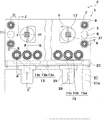
도 1은 본원 발명에 의한 적층물 피치 변경 장치의 실시형태를 도시하는 일부 생략 주요부 절결 정면도이다.
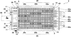
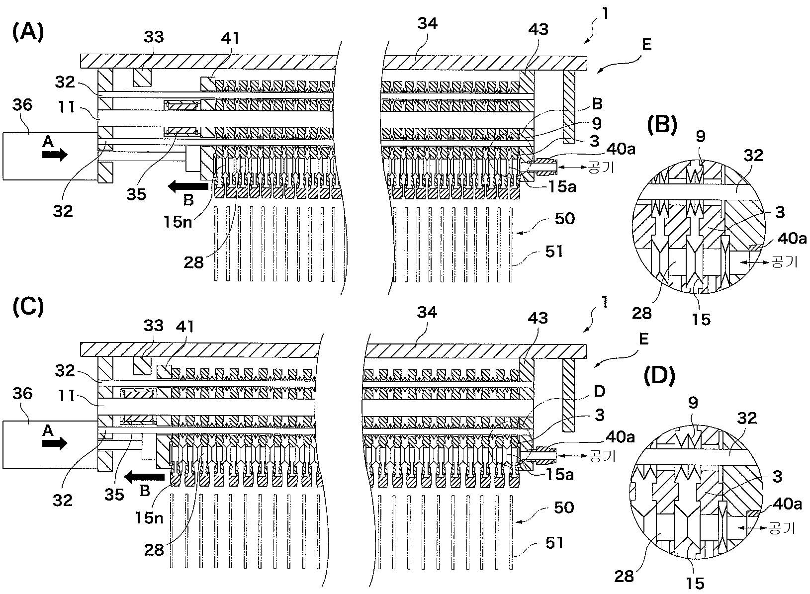
도 2(A)는 스프링의 축소시에 있어서의 도 1의 A-B-C-D의 단면도, 도 2(B)는 도 2(A)의 B부 확대도, 도 2(C)는 스프링의 확장시에 있어서의 도 1의 A-B-C-D의 단면도, 도 2(D)는 도 2(C)의 D부 확대도이다.
도 3(A)는 가변 스페이서의 작은 피치 시에 있어서의 도 1의 E-F-G-H-I-J의 단면도, 도 3(B)는 도 3(A)의 B부 확대도, 도 3(C)는 가변 스페이서의 큰 피치 시에 있어서의 도 1의 E-F-G-H-I-J의 단면도, 도 3(D)는 도 3(C)의 D부 확대도이다.
도 4는 도 3(A)의 평면도이다.
도 5(A)는 베이스 플레이트 및 그 장착물을 도시하는 정면도, 도 5(B)는 도 5(A)의 B-B 확대 단면도이다.
도 6(A)는 도 1의 흡착 패드의 정면도, 도 6(B)는 도 6(A)의 저면도, 도 6(C)는 도 6(A)의 우측면도이다.
도 7(A)는 가변 스페이서의 정면도, 도 7(B)는 도 7(A)의 B-B 단면도, 도 7(C)는 도 7(B)의 C부 확대도이다.
도 8(A)는 연통로의 위치를 도시하는 도면, 도 8(B)는 연통로의 다른 위치를 도시하는 도면, 도 8(C)는 연통로의 또 다른 위치를 도시하는 도면이다.
도 9는 연통로의 위치를 도시하는 평면도이다.
도 10은 도 1의 적층물 피치 변경 장치에 사용하는 해제 스프링을 도시하는 일부 단면 정면도이다.
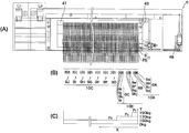
도 11(A)는 도 1의 우측면도, 도 11(B)는 도 11(A)의 해제 스프링의 블록마다의 조합을 도시하는 도면, 도 11(C)는 해제 스프링의 복원력을 모식적으로 나타낸 그래프이다.
도 12는 도 1의 장치의 연통로를 개폐하는 밸브 및 오리피스를 나타내는데, 도 12(A)는 밸브가 열린 상태일 때, 도 12(B)는 밸브가 닫힌 상태일 때를 도시하는 도면이다.
도 13은 본원 발명에 의한 적층물 피치 변경 장치의 동작 플로우를 나타내는 도면이다.
도 14(A)는 다른 동작 부재의 정면도, 도 14(B)는 도 14(A)의 저면도, 도 14(C)는 도 14(A)의 우측면도이다.BRIEF DESCRIPTION OF THE DRAWINGS FIG. 1 is a partially cutaway front view showing an embodiment of a laminate pitch changing device according to the present invention. FIG.
Fig. 2 (A) is a sectional view of ABCD in Fig. 1 when the spring is contracted, Fig. 2 (B) is an enlarged view of a portion B in Fig. Fig. 2 (D) is an enlarged view of part D in Fig. 2 (C). Fig.
Fig. 3 (A) is a sectional view of EFGHIJ in Fig. 1 at a small pitch of a variable spacer, Fig. 3 (B) is an enlarged view of a portion B in Fig. Fig. 3 (D) is an enlarged view of part D in Fig. 3 (C). Fig. 3 (A) is a sectional view of EFGHIJ in Fig.
Fig. 4 is a plan view of Fig. 3 (A).
Fig. 5 (A) is a front view showing the base plate and its attachment, and Fig. 5 (B) is an enlarged cross-sectional view of BB in Fig. 5 (A).
Fig. 6A is a front view of the adsorption pad of Fig. 1, Fig. 6B is a bottom view of Fig. 6A, and Fig. 6C is a right side view of Fig.
Fig. 7A is a front view of the variable spacer, Fig. 7B is a cross-sectional view taken along line BB of Fig. 7A, and Fig.
Fig. 8A is a view showing the position of the communication passage, Fig. 8B is a view showing another position of the communication passage, and Fig. 8C is a view showing another position of the communication passage.
9 is a plan view showing the position of the communication path.
10 is a partial cross-sectional front view showing a release spring for use in the apparatus for changing the stack pitch of Fig.
Fig. 11 (A) is a right side view of Fig. 1, Fig. 11 (B) is a view showing a combination of each release spring of Fig. 11 (A) Fig.
Fig. 12 shows a valve and an orifice for opening and closing a communication path of the apparatus of Fig. 1, wherein Fig. 12 (A) is a view showing a state in which the valve is open, and Fig.
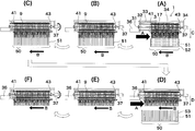
13 is a view showing an operational flow of a laminate pitch changing apparatus according to the present invention.
Fig. 14A is a front view of another operating member, Fig. 14B is a bottom view of Fig. 14A, and Fig. 14C is a right side view of Fig.
(발명을 실시하기 위한 형태)(Mode for carrying out the invention)
다음에 실시형태를 도시하는 도면에 기초하여 본원발명에 의한 적층물 피치 변경 장치를 더욱 상세하게 설명한다. 또한, 편의상 동일한 기능을 수행하는 부분에는 동일한 부호를 붙이고 그 설명을 생략한다. Next, a laminate pitch changing device according to the present invention will be described in more detail with reference to the drawings showing embodiments. For convenience, the same reference numerals are used for the same parts, and a description thereof will be omitted.
도 1 내지 도 4에 도시하는 바와 같이, 본원 발명에 의한 적층물 피치 변경 장치(E)는 이동 자유로운 가동 유지부로서의 가동 흡착부(1)와, 이 가동 흡착부(1)를 구동하는 구동부로 이루어진다. 상기 가동 흡착부(1)는 다수의 베이스 플레이트(3)가 소정의 피치로 적층 형상으로 나란히 배치되어 이루어진다. 상기 가동 흡착부(1)를 구성하는 1군의 베이스 플레이트(3)는 각각 동일 구성의 사각형의 판상 편으로 이루어진다. 각 베이스 플레이트(3)는, 도 5에 상세하게 도시하는 바와 같이, 중앙부에 한 쌍의 구멍부(5)를 설치한다. 이 구멍부(5)는 바닥을 갖고, 가변 스페이서(17)를 작은 피치부(19)로 했을 때, 큰 피치부(20)가 빠져나갈 수 있도록 가변 스페이서(17)의 반경보다 큰 사각형 형상의 구멍(5a)으로 형성된다. 이 사각형 형상의 구멍(5a)의 외변측의 중앙부에는 외방을 향하여 반원 형상의 절결부(5b)가 설치되어, 구동축(31)이 회전할 때의 여유부를 형성한다. 도시된 실시예에서는, 구멍부(5)의 절결부(5b)는 바닥을 가지고 있으므로, 작은 피치 시에 절결부(5b)에 위치하는 큰 피치부(20)의 과도한 진입을 방지할 수 있으므로 바람직하다. 각 베이스 플레이트(3)의 좌우의 양단부에는 상하에 2개의 원형의 오목부(7)를 설치한다. 이 오목부(7)에는, 도 2(B), 도 2(D)에 상세하게 도시하는 바와 같이, 접시 형상의 스프링(9o)이 4장 겹침으로 되어, 벨로우즈 형상의 해제 스프링(9)으로서 장착된다. 이 오목부(7)의 사이에는 둥근 구멍(8)이 설치되고, 이 둥근 구멍(8)에 환봉으로 이루어지는 슬라이드 가이드(11)가 삽입통과된다. 각 베이스 플레이트(3)의 하단부에는 원형 형상의 통과구멍(13a, 13b, 13c)이 3개씩 한 쌍으로 설치되고, 여기에 신축 자유로운 유연성 소재로 이루어지는 탄성 패킹(15a, 15b, 15c)(총칭할 때는「탄성 패킹(15)」이라고 함)을 부착한다. 또한 상기 통과구멍(13a, 13b, 13c)에는, 도 2(A) 내지 도 2(D)에 상세하게 도시하는 바와 같이, 각각, 관통구멍을 갖는 조인트(40a, 40b, 40c)(총칭할 때는「조인트(40)」라고 함)가 공기의 출입이 자유롭게 연결된다. 1 to 4, the laminate pitch changing device E according to the present invention includes a
각 베이스 플레이트(3)에는 상기 절결부(5b)의 중심에 가변 스페이서(17)가 배치된다. 이 가변 스페이서(17)는 각봉(角棒)으로 이루어지는 회전 가능한 구동축(31)에 삽입통과된다. 이 가변 스페이서(17)는, 도 7에 도시하는 바와 같이, 원판으로 이루어지고, 중앙부에 상기 구동축(31)을 삽입통과하는 정방형의 중심구멍(18)이 설치된다. 이 가변 스페이서(17)는 원주면의 두께가 상이하고, 비교적 얇은 두께(d1)를 갖는 작은 피치부(19)와 두꺼운 두께(d2)를 갖는 큰 피치부(20)를 설치하여 이루어진다. 상기 작은 피치부(19)와 상기 큰 피치부(20)는 경사부(21)를 통하여 연속된다. Each
상기 가변 스페이서(17)는 각 베이스 플레이트(3) 사이에 배치되고, 각봉으로 이루어지는 회전 가능한 구동축(31)에 삽입통과된다. 이것에 의해, 상기 가변 스페이서(17)는 구동축(31)의 회전에 연동하여 회전하고, 인접하는 베이스 플레이트(3)에 맞닿는 작은 피치부(19) 또는 큰 피치부(20)의 작용면이 변경됨과 아울러, 상기 베이스 플레이트(3)의 수평방향의 이동에 연동하여 수평방향으로 이동된다. The
상기 통과구멍(13a, 13b, 13c)(총칭할 때는「통과구멍(13)」이라고 함)의 또한 하단부에는, 분배 플레이트(23)를 상기 베이스 플레이트(3)와 일체로 교환 가능하게 고착한다. 이 분배 플레이트(23)의 하단부에는 동작 부재로서의 흡착 패드(25)를 교환 가능하게 부착한다. 상기 분배 플레이트(23)에는 통로(26)가 내설되고, 이 통로(26)가 상기 흡착 패드(25)에 내설되는 작은 통로(27)에 연통된다. The
상기 베이스 플레이트(3)의 통과구멍(13)에 부착되는 탄성 패킹(15)과, 상기 분배 플레이트(23)에 내설되는 통로(26)와, 상기 흡착 패드(25)에 내설되는 작은 통로(27)에 의해, 신축 자유로운 연통로(28)가 형성된다. 이 연통로(28)는 상기 흡착 패드(25)에 설치되는 흡착구(29)에 연통된다. 이 흡착구(29)는 경험상 갈라짐, 깨짐이 많이 발생하는 워크(51)의 부위에 대응하는 흡착 패드(25)의 부위에 설치하는 것이 바람직하다. 본 실시예의 경우, 각 통과 구멍(13)은 제 1 통과 구멍(13a)이 1장째 내지 10장째의 워크(51)에, 제 2 통과 구멍(13b)이 동 11장째 내지 20장째의 워크(51)에, 제 3 통과 구멍(13c)이 동 21장째 내지 30장째의 워크(51)에 각 대응하도록 구성되고, 도 8에 사선으로 나타내는 바와 같이, 각각, 제 1 연통로(28a)(도 8(A)), 제 2 연통로(28b)(도 8(B)), 제 3 연통로(28c)(도 8(C))를 형성한다. 27a는 상기 작은 통로(27)와 상기 흡착구(29)와의 경계에 형성되는 협착부이다(도 5 및 도 6에 나타냄). 이 협착부(27a)의 개구는 단면적의 비에서 후기하는 오리피스(46)의 개구보다 크게 설정된다. The
도 2 및 도 9에 있어서, 32는 상기 각 해제 스프링(9)을 연통하는 가이드 로드, 33은 받침대(34)에 설치되고 1군의 베이스 플레이트(3)의 벌어짐 끝부에 맞닿는 스토퍼, 35는 상기 푸시 플레이트(41)의 벌어짐 끝부측에 설치되는 슬라이드 부시, 36은 워크(51) 사이의 피치를 정하는 진퇴 자유로운 피치 결정 실린더이다. 40a는 1장째 내지 10장째의 워크(51)용의 제 1 조인트, 40b는 11장째 내지 20장째의 워크(51)용의 제 2 조인트, 40c는 21장째 내지 30장째의 워크(51)용의 제 3 조인트이다. 각 조인트(40a, 40b, 40c)는 각각 1장째 내지 10장째의 워크(51)용의 제 1 연통로(28a), 11장째 내지 20장째의 워크(51)용의 제 2 연통로(28b), 21장째 내지 30장째의 워크(51)용의 제 3 연통로(28c)에 연결된다. 또 각 조인트(40a, 40b, 40c)는, 도시하지 않은 진공원에 연결되고, 진공원으로부터의 구동 파워를 상기 각 연통로(28a, 28b, 28c)에 전달한다. 도 3 및 도 4에 있어서, 37은 상기 구동축(31)을 구동시키는 회전 액추에이터, 38은 이 회전 액추에이터(37)의 구동력을 상기 구동축(31)에 전달하는 커플링, 39는 상기 구동축(31)의 양단부에 설치되는 베어링, 41은 1군의 베이스 플레이트(3)의 벌어짐 끝부에 설치되는 진퇴 자유로운 푸시 플레이트, 43은 1군의 베이스 플레이트(3)의 기단부에 설치되는 고정 기준 플레이트이다. 도면에서, 화살표 A는 상기 피치 결정 실린더(36)의 누름 방향을, 화살표 B는 상기 해제 스프링(9)의 복원력의 방향을 각각 나타낸다. 2 and 9,
여기에서 해제 스프링(9)에 대하여 상세하게 기술한다. 해제 스프링(9)을 구성하는 스프링(9o)은, 도 10에 도시하는 바와 같이, 중앙부(9p)에 구멍이 형성되고, 주연부(9q)가 경사져서 이루어지고, 상기한 바와 같이, 4장 겹침으로 하여 베이스 플레이트(3)에 장착된다. 도 11(A) 및 도 11(B)에 도시하는 바와 같이, 중앙부(9p)를 대향시킨 2쌍의 스프링(9o)의 바닥면부(9r)를 대향시켜 1쌍의 해제 스프링(9)을 구성한다. 축소된 상태의 베이스 플레이트(3)를 복원시키기 위한 스프링력은 기준 플레이트(43)측의 스프링의 복원력을 푸시 플레이트(41)측의 스프링의 복원력보다 크게 설정된다. 각 조합의 해제 스프링(9)의 스프링력은, 도 11 실시예의 경우, 3개의 블록(10A, 10B, 10C)으로 나누어 설정되어 있다. 제 1 블록(10A) 내지 제 3 블록(10C)을 구성하는 각 해제 스프링(9)의 스프링력의 관계에 대하여 보면, 워크(51)의 단위 개수(도시예는 5매)마다 소정의 비율씩 스프링력을 증강시키고, 도 11(C)에 도시하는 바와 같이, 계단 모양으로 해제 스프링(9)의 복원력을 증강시키고 있다. 즉, 제 1 블록(10A)의 해제 스프링(9A)의 스프링력(P1)>제 2 블록(10B)의 해제 스프링(9B) 또는 해제 스프링(9C)의 각 스프링력(P2)>제 3 블록(10C)의 해제 스프링(9D) 내지 해제 스프링(9J)의 각 스프링력(P3)으로 되어 있다. 또한 제 1 블록(10A)의 해제 스프링(9A)은 구성 스프링(9a)을 대강도, 구성 스프링(9b)을 중강도, 구성 스프링(9c, 9d)을 소강도의 스프링력으로 구성한다. 제 2 블록(10B)의 해제 스프링(9B)은 구성 스프링(9e)을 대강도, 구성 스프링(9f, 9g, 9h)을 소강도로 구성한다. 해제 스프링(9C)을 구성하는 스프링의 스프링력도 또한 마찬가지로 구성된다. 제 3 블록(10C)의 해제 스프링(9D) 내지 해제 스프링(9J)의 스프링력은 4개의 각 구성 스프링을 모두 소강도의 스프링력으로 구성한다. 또한, 도 11(A)에 도시하는 베이스 플레이트(3)의 개수는, 도 2 내지 도 4에 도시하는 베이스 플레이트(3)의 개수와 정확하게 일치하고 있지 않은데, 이것은 설명의 사정상 편의적으로 나타냈기 때문이다. 도 11(C)에서, X축은 작은 피치 시에 있어서의 해제 스프링(9)의 위치를 나타내고, Y축은 작은 피치 시에 있어서의 해제 스프링(9)의 스프링력을 나타낸다. Here, the
상기 연통로(28)는, 도 12에 도시하는 바와 같이, 챔버 블록(42)의 진공 공급 챔버(44)에 설치되고, 여기에 이 진공 공급 챔버(44)를 개폐하는 밸브(45)가 설치된다. 46은 이 개폐 밸브(45)에 내설되는 오리피스이다. 47은 챔버 블록(42)에 설치된 진공압 검출로이다. 이 진공압 검출로(47)의 일단부는 상기 진공 공급 챔버(44)에 연통되는 소로(小路)(47a)를 거쳐, 상기 오리피스(46)에 연통되고, 타단부는 다른 조인트(40d)를 거쳐 진공압 검출 센서(48)(도 11에 가리킨다)에 접속된다. 49는 상기 개폐 밸브(45)를 구동시키는 실린더이다. 상기 개폐 밸브(45), 상기 오리피스(46), 상기 소로(47a), 상기 진공압 검출로(47) 및 진공압 검출 센서(48)에 의해 워크 상태 검출부를 구성한다. 12, the
그런데, 상기 오리피스(46)는 상기 흡착 패드(25)와의 개구비가 중요하다. 즉, 상기 오리피스(46)의 개구 면적은 상기 흡착 패드(25)에 설치한 상기 협착부(27a)의 개구 면적보다 작은 것을 요한다. 본 실시예에서는 오리피스(46)의 개구는 단면적비로 협착부(27a)에 대하여 약 1/6로 되어 있다. However, the opening ratio of the
다음에 도 13에 기초하여 하나의 피치(예를 들면, 작은 피치)로 소용기(52)에 적층 상태로 수납되어 있는 적층물을, 다른 피치(예를 들면, 큰 피치)로 변경하여 대용기(53)에 적층 상태로 수납하는 경우의 동작에 대하여 설명한다. 또한, 미리 가변 스페이서(17)의 작은 피치부(19)의 치수는 소용기(52)에 수납되는 워크(51) 간의 피치로 설정되고, 또한 가변 스페이서(17)의 큰 피치부(20)의 치수는 대용기(53)에 수납되는 워크(51) 간의 피치로 설정되어 있다. Next, based on Fig. 13, the laminate stored in the laminated state in the
우선 피치 결정 실린더(36)를 신장시키고, 푸시 플레이트(41)에 의해 베이스 플레이트(3)를 기준 플레이트(43)측으로 누르고, 베이스 플레이트(3) 간의 피치를 소용기(52)에 적층상태로 수납되어 있는 워크(51) 간의 피치(도 3(A), 도 3(B)에 도시하는 작은 피치)에 대응시킨다(도 13(A)). The
이어서, 가동 흡착부(1)를 도 13(A)에 도시하는 화살표 C 방향으로 수직이동시켜, 작은 피치의 소용기(52) 내에 삽입한다. 가동 흡착부(1)의 각 베이스 플레이트(3)는 각 흡착 패드(25)를 각 워크(51) 사이에 삽입하고, 각 흡착 패드(25)에 각 워크(51)를 흡착한다. 각 흡착 패드(25)는 적층방향에 직교하는 방향의 워크의 면, 즉, 워크(51)의 정면(51a)(도 1에 1점 쇄선으로 나타냄) 또는 배면을 흡착한다. Subsequently, the
이 흡착은 도시하지 않은 진공원에 의해 연통로(28) 내부를 감압하고, 각 워크(51)를 각 흡착 패드(25)의 흡착구(29)에 흡착시킨다. 이 때 연통로(28) 내의 감압은 제 1 연통로(28a), 제 2 연통로(28b), 제 3 연통로(28c)를 동시에 작동시킨다. 이것에 의해, 소용기(52)에 적층 상태로 수납되어 있는 적층물(50)의 가동 흡착부(1)에 대한 세팅이 완료된다. This adsorption decompresses the inside of the
이어서 가동 흡착부(1)를 화살표 C 반대 방향으로 수직이동시켜 소용기(52)로부터 적층물(50)을 빼낸 후, 가동 흡착부(1)를 수평방향으로 이동하고, 가동 흡착부(1)를 워크(51) 사이의 피치가 상이한 대용기(53)까지 이동한다. Subsequently, the
이 대용기(53)로의 이동 중에, 베이스 플레이트(3) 간의 피치를 도 3(C), 도 3(D)에 도시하는 큰 피치로 변경한다. 이 과정을 나타내는 것이 도 13(B), 도 13(C)이다. During the movement to the
우선, 각 베이스 플레이트(3)는, 각각, 세팅되어 있는 해제 스프링(9)의 복원력에 의해 푸시 플레이트(41)측으로 눌리므로, 가동 흡착부(1)는 축소 상태로부터 벌어짐 끝부까지 확장된다. 도 13(B)는 이 상태를 나타낸다. 이때 해제 스프링(9)은 기준 플레이트(43)측의 스프링의 복원력을 푸시 플레이트(41)측의 스프링의 복원력보다 크게 설정하고 있기 때문에, 가동 흡착부(1)의 확장이 원활하게 된다. First, each
이어서 회전 액추에이터(37)를 회전시킨다. 그러면 회전 액추에이터(37)에 삽입통과되어 있는 각 가변 스페이서(17)가 회전하고, 큰 피치부(20)가 베이스 플레이트(3)에 맞닿는다. 도 13(C)는 이 상태를 나타낸다. Then, the
이어서 피치 결정 실린더(36)를 신장시키고, 각 베이스 플레이트(3)에 맞닿는 각 가변 스페이서(17)의 작용면을 도 7(B)에 도시하는 큰 피치(d2)로 고정한다. 도 13(D)는 이 상태를 나타낸다. The
이 상태에서 가동 흡착부(1)를 도 13(D)에 나타내는 화살표 D 방향에 수직이동시키고, 이어서 각 흡착 패드(25)의 흡착을 해제하고, 워크(51)를 적층 상태 그대로 큰 피치의 대용기(53)에 수납한다(도 13(D)). 이 옮김에 있어서의 흡착 해제 시에도, 연통로(28)의 감압의 해제는 제 1 연통로(28a), 제 2 연통로(28b), 제 3 연통로(28c)를 동시에 행한다. In this state, the
이어서, 가동 흡착부(1)를 도 13(D)에 나타내는 화살표 D 반대 방향으로 수직이동시킨 후, 피치 결정 실린더(36)를 축소시키면, 각 베이스 플레이트(3)는 각각 세팅되어 있는 해제 스프링(9)의 복원력에 의해 푸시 플레이트(41)측으로 눌려지므로, 가동 흡착부(1)는 벌어짐 끝부까지 확장된다. 이것에 의해 각 베이스 플레이트(3)에 맞닿아 있던 각 가변 스페이서(17)의 고정이 해제된다. 도 13(E)는 이 상태를 나타낸다. 이때도 해제 스프링(9)은 기준 플레이트(43)측의 스프링의 복원력이 푸시 플레이트(41)측의 스프링의 복원력보다도 크게 설정되어 있기 때문에, 가동 흡착부(1)의 확장이 원활하게 된다. Subsequently, when the
이어서 회전 액추에이터(37)를 회전시킨다. 그러면 회전 액추에이터(37)에 삽입통과되어 있는 각 가변 스페이서(17)가 회전하고, 작은 피치부(19)가 베이스 플레이트(3)에 맞닿는다. 도 13(F)는 이 상태를 나타낸다. Then, the
이어서 피치 결정 실린더(36)를 신장시키고, 각 베이스 플레이트(3)에 맞닿는 각 가변 스페이서(17)의 작용면을 도 7(B)에 도시하는 작은 피치(d1)로 고정한다. 이것에 의해 도 13(A)에 도시하는 최초의 상태로 되돌아오게 된다. The
용기 내에 수납된 워크수가 많을 때는, 옮김 작업이 종료할 때까지 상기 스텝을 반복한다. When the number of works housed in the container is large, the above steps are repeated until the transfer operation is completed.
큰 피치로 설정된 용기(53)로부터 작은 피치로 설정된 용기(52)로의 옮김에 대해서도 상기와 동일하며, 이때는 도 13(D)의 상태로부터 스타트하여, 도 13(E), 도 13(F), 도 13(A), 도 13(B), 도 13(C)와 같이, 상기한 스텝을 거쳐 도 13(D)의 상태로 되돌아온다. (E), Fig. 13 (F), and Fig. 13 (D), the same operation as described above is performed for the transfer from the
각 흡착 패드(25)에 의한 각 워크(51)의 흡착은, 각 베이스 플레이트(3)의 통과구멍(13)에 신축 자유로운 탄성 패킹(15)이 부착되고, 이것에 의해 구성된 연통로(28)를 통하여 상기 동작이 행해지고 있다. 따라서 연통로(28)의 기밀성이 보장되므로, 1군의 적층물(50)의 옮김을 워크(51)의 적층 상태를 유지한 채 행할 수 있다. 따라서 적층물(50)의 피치를 변경한 옮김을 원활하고, 신속하고, 효율적으로 행할 수 있다. The adsorption of each
이 점을 더욱 상세하게 설명한다. 각 연통로(28)는 탄성 패킹(15)을 통하여 각 흡착 패드(25)의 흡착구(29)까지 연통되어 있는 바, 이 탄성 패킹(15)은 베이스 플레이트(3)의 이동에 연동하여 수평방향으로 그 위치를 이동한다. 각 탄성 패킹(15)의 신축 폭은, 1개 1개에 대해서는 근소한 것이지만, 가령 각 탄성 패킹(15)이 이동하지 않은 경우에는, 기준 플레이트(43)측에 인접하는 탄성 패킹(15a)의 이동량과 벌어짐 끝부가 되는 푸시 플레이트(41)에 인접하는 탄성 패킹(15n)의 이동량에서는 큰 벌어짐으로 된다. 예를 들면, 각 탄성 패킹(15)의 신축 폭을 0.8mm로 한 경우, 가령 각 탄성 패킹(15)이 이동하지 않는다고 한 경우에는, 탄성 패킹(15a)의 이동량은 0.8mm이지만, n개째가 30개째일 때의 탄성 패킹(15n)의 이동량은 본 실시예에서는「0.8mm×(30-1)=23.2mm」의 큰 이동량이 된다. 따라서, 각 탄성 패킹(15)이 이동 자유롭지 않은 경우에는, 기준 플레이트(43)측으로부터 막 벗어났을 때의 탄성 패킹(15)을 구성요소로 하는 연통로(28)의 감압 진공은 파탄되게 되어, 워크(51)의 흡착이 곤란하게 된다. 그렇지만, 본원발명에서는, 각 탄성 패킹(15)은 베이스 플레이트(3)의 이동에 연동하여 수평방향으로 이동 자유롭기 때문에, 이 정도(0.8mm)의 신축폭은 신축 자유로운 탄성 패킹(15)이 흡수한다. 따라서, 탄성 패킹(15a)(도 2에 도시하는 (A), (C)에 나타냄)의 신축 폭 내지 탄성 패킹(15n)(도 2에 도시하는 (A) (C)에 나타냄)의 신축 폭은 어느 경우도 일정(본 실시예에서는 0.8mm)하며, 탄성 패킹(15)의 설치 부위에 의해 이동량이 변경되지 않고, 항상 연통로(28)의 기밀성이 보장된다. 게다가 이 연통로(28)의 기밀성의 보장은 탄성 패킹(15)의 개수에 영향받지 않는다. This point will be described in more detail. Each of the
또한 상기 실시형태에 의하면, 각 베이스 플레이트(3)에 흡착 패드(25)가 1쌍 설치되어 있기 때문에, 워크(51)를 흡착하여 지지할 때, 예를 들면, 해제 스프링(9)의 배치가 좌우 대칭 또한 슬라이드 가이드(11)에 대하여 상하 대칭이 되고, 또한 가변 스페이서(17)의 배치가 좌우 대칭이 되어 밸런스를 잡기 쉬워, 장치가 기계적으로 더한층 안정된 효과가 있다. According to the above embodiment, a pair of
또한 상기 실시형태에서는, 적층물인 워크의 적층 상태를 유지한 채 30장의 워크(51)의 옮김을 단숨에 행할 수 있다. 따라서, 옮김 작업을 확실하고, 안정적으로 행할 수 있다. Further, in the above embodiment, it is possible to carry out the transfer of thirty pieces of
또한 상기 실시형태에서는 1군의 워크(51)를 그룹마다 3개의 연통로(28)의 관할에 의해 처리하므로, 하나의 그룹, 예를 들면, 제 1 연통로(28a)에 소속되는 베이스 플레이트(3)에 어떠한 이상이 발생한 경우에도, 다른 그룹에 소속되는 제 2 연통로(28b) 및 제 3 연통로(28c)의 작동을 계속할 수 있다. 따라서, 이 점으로부터도 옮김 작업의 효율화를 도모할 수 있다. 또한 그룹마다 옮김 작업의 내용을 변경하는 것도 가능하다. In the above embodiment, the
또한 상기 실시형태에서는, 기준 플레이트(43)측의 해제 스프링(9)에 걸리는 부하는 항상 푸시 플레이트(41)측의 해제 스프링(9)에 걸리는 부하보다 크게 되므로, 해제 스프링(9)은 기준 플레이트(43)측의 복원력이 푸시 플레이트(41)측의 복원력보다 크게 되어 있다. 따라서, 베이스 플레이트(3) 사이의 피치의 변경시, 즉, 해제 스프링(9)에 의해 베이스 플레이트(3)가 도 13(A)로부터 도 13(B)의 위치로 눌려질 때, 또한 도 13(D)로부터 도 13(E)의 위치로 눌려질 때, 베이스 플레이트(3) 전체가 밸런스 좋게 눌려지므로, 옮기기 전의 위치로의 베이스 플레이트(3)의 복원을 원활하게 행할 수 있다. 이 점에 관하여, 해제 스프링의 강도를 균일하게 해 두면, 해제 스프링이 작동하지 않는 경우가 있다. The load applied to the
도 11의 실시예의 경우, 기준 플레이트(43)측의 제 1 블록(10A)의 해제 스프링(9A)의 누름력(P1)은 190kg, 제 2 블록(10B)의 해제 스프링(9b, 9C)의 누름력(P2)은 170kg, 제 3 블록(10C)의 해제 스프링(9D∼9J)의 누름력(P3)은 150kg으로 되어 있다. 이와 같이 복원력에 차를 갖게 한 해제 스프링(9)을 베이스 플레이트(3)에 설치하면, 베이스 플레이트(3)의 해제 스프링(9)이 동시에 확장 복원되어 가기 때문에, 블록 형상으로 축소되어 있던 1군의 베이스 플레이트(3)가 균등하게 확장되어, 다음 스텝으로 이행할 수 있다. 11, the pressing force P 1 of the
그런데, 흡착 패드(25)에 의한 워크(51)의 흡착 스텝에서 워크(51)에 갈라짐, 깨짐 등의 이상 상태가 있으면, 그 갈라짐, 깨짐으로부터 에어가 침입되어 온다. 이 경우에 있어서, 도 12에 도시하는 워크 상태 검출부를 구비하고 있을 때는, 갈라짐, 깨짐으로부터 유입되는 에어에 의해 연통로(28) 내의 압력이 상승하므로, 진공압 검출 센서(48)는 이 에어의 압력을 감지하여, 이상 신호를 발한다. 이 이상 신호는 도시하지 않은 표시기에 디지털 표시되어도 되고, 되지 않아도 된다. 또한, 워크(51)가 정상일 때는, 오리피스(46)로부터 유출되고 있는 에어의 유출량은 근소하기 때문에, 흡착 패드(25)에 의한 워크(51)의 흡착 지지에는 영향이 없다. However, if there is an abnormal state such as cracking or cracking in the
또한 워크(51)에 갈라짐, 깨짐 등의 이상 상태가 있는 경우, 연통로(28) 내의 진공압이 변화되므로, 옮기기 전에 이 변화를 검출할 수 있다. 따라서 옮김의 확실성이 더한층 향상된다. In addition, when there is an abnormal state such as cracking or breakage in the
본원 발명에 의한 적층물 피치 변경 장치는 상기한 실시형태에 제한되지 않는다. 예를 들면, 동작 부재에 의한 유지는, 흡착 패드(25)에 의한 흡착이 아니고, 도 14에 도시하는 바와 같이, 협착 부재(65)에 의한 협착에 의해 각 워크(51)를 유지하는 것이어도 되고, 이러한 경우에도 본원발명을 적용할 수 있다. 도 14의 경우, 협착 부재(65)는 스프링(65c)에 의해 연결된 한 쌍의 개폐 자유로운 가동부(65a, 65b) 로 이루어지고, 기단부에 상기 연통로(28)에 연통되는 통로(66)가 설치된다. 상기 스프링(65c)은 평상시에 벌어진 상태로 가압되어 있다. 상기 연통로(28) 내부가 진공원에 의해 감압되어 스프링(65c)의 가압력을 이기면, 가동부(65a, 65b)가「닫힘」으로 되고, 도 14(A), 도 14(B)에 1점 쇄선으로 나타내는 바와 같이, 가동부(65a, 65b) 워크(51)의 측면(51b)을 협지한다. The laminate pitch changing device according to the present invention is not limited to the above-described embodiment. For example, as shown in Fig. 14, the holding by the operating member may be performed not by the suction by the
또한 흡착 패드(25), 협착 부재(65)와 같은 동작 부재는 반드시 한 쌍을 요하는 것은 아니고, 1개이어도 되고, 또한 3개 이상이어도 된다. 동작 부재에 의한 워크의 피지지면은 임의이며, 예를 들면, 도 14(A)에 도시하는 바와 같이, 적층 방향을 따른 방향의 워크의 면, 즉, 워크의 양측면(51b)으로부터 워크(51)를 협착해도 된다. In addition, the operating members such as the
연통로(28)의 개수는 임의이며, 적용되는 워크의 매수에 의해 적당히 증감 가능하다. The number of the
연통로(28)를 복수 설치하는 경우, 그 작동은 차례로 동작시킬 수도 있다. 이것은, 예를 들면, 진공원의 용량이 작은 경우에 유리하다. When a plurality of
탄성 패킹(15)은 도시된 실시형태에서는 벨로우즈 형상의 것을 나타냈지만, 이것에 한정되지 않고, 예를 들면, 탄성력이 있는 고무패킹, O링 등을 사용할 수도 있다. 어떻든 베이스 플레이트(3)의 이동에 연동하여 이동 자유롭게 된다. Although the
가변 스페이서(17)의 원주면에 형성되는 피치부도, 예를 들면, 대중소의 3개 이상으로 할 수 있다. 예를 들면, 피치부를 3개로 하는 경우에는, 각 피치부는 120°마다 설치한다고 하는 것과 같이, 피치부의 복수 설치의 경우에는 피치부의 설치 부위를 적당히 변경한다. The pitch portion formed on the circumferential surface of the
또한 피치부의 설치 비율은 반드시 등분으로 할 필요는 없다. 예를 들면, 대소의 피치부로 하는 경우, 큰 피치부의 설치 비율을 60%, 작은 피치부의 설치 비율을 40%와 같이 할 수도 있다. 또 대중소의 피치부로 하는 경우, 큰 피치부의 설치 비율을 40%, 중간 피치부의 설치 비율을 35%, 작은 피치부의 설치 비율을 25%와 같이 할 수도 있다. In addition, the installation ratio of the pitch portion does not necessarily have to be equal. For example, in the case of a large and small pitch portion, the installation ratio of the large pitch portion may be set to 60%, and the installation ratio of the small pitch portion may be set to 40%. In the case of a large-scale pitch portion, it is also possible to set the installation ratio of the large pitch portion to 40%, the installation ratio of the middle pitch portion to 35%, and the installation ratio of the small pitch portion to 25%.
베이스 플레이트(3) 사이의 피치를 변경하는 시기는 임의이다. 도시 실시형태와 같이 워크(51)의 반송중이어도 되지만, 반송 전의 소용기(52)로의 가동 유지부의 수직이동시에, 또한 반송 후의 대용기(53)로의 가동 유지부의 수직이동시에, 베이스 플레이트(3) 간의 피치를 변경해도 된다. The timing for changing the pitch between the
또한 가동 유지부의 이동방향은 임의이다. 상기 실시형태에서는 가동 유지부를 수평방향으로 이동하는 경우를 진술했지만, 가동 유지부를 수직방향으로 이동해도 되고, 경사 방향으로 이동해도 된다. The moving direction of the movable holding portion is arbitrary. In the above embodiment, the case where the movable holding portion is moved in the horizontal direction is described. However, the movable holding portion may be moved in the vertical direction or in the slanting direction.
가동 유지부를 구성하는 베이스 플레이트(3)의 적층방향은 임의이다. The direction of stacking the
또한 베이스 플레이트(3)의 형상은 임의이다. The shape of the
각 부의 소재는 임의이지만, 베이스 플레이트(3), 가변 스페이서(17), 해제 스프링(9)은 내구성이 큰 소재, 예를 들면, 금속계 소재가 바람직하다. 또한 탄성 패킹(15)은 탄성력이 큰 소재, 예를 들면, 플라스틱 소재, 고무 소재가 바람직하다. 흡착 패드(25)는 경량성, 가공성, 내약품성의 점 및 워크보다도 경도가 작은 소재, 예를 들면, 적당한 플라스틱 소재가 바람직하다. 분배 플레이트(23)는 경량성, 가공성의 점에서, 예를 들면, 적당한 플라스틱 소재, 경량 금속 소재가 바람직하다. The
또한, 구동 파워는 임의이며, 진공원에 의할 뿐만이 아니라, 예를 들면, 가압원이어도 된다. Further, the driving power is arbitrary, and it may be, for example, a pressure source as well as a vacuum source.
또한 해제 스프링(9)의 스프링력에 관하여, 기준 플레이트(43)측의 베이스 플레이트(3)에 설치하는 해제 스프링(9)의 스프링 복원력을 최대로 하고, 푸시 플레이트(41)측의 해제 스프링(9)을 향하여 차례로 직선상으로 작게 하는 것이 바람직한 것이지만, 전술한 바와 같이, 베이스 플레이트(3)의 소정의 개수(단위수)마다 푸시 플레이트(41)측을 향하여 계단 모양으로 작게 하는 경우이어도 되는 것이 실증되었다. With respect to the spring force of the
또한 해제 스프링(9)의 개수 및 이것을 재치하는 오목부(7)의 개수도 임의이며, 설정되는 피치의 치수에 의해 적당하게 증감 가능하다. Also, the number of the release springs 9 and the number of the
또한 본원 발명에 의한 적층물 피치 변경 장치는 상기한 실시형태에 제한되지 않는다. 예를 들면, 개폐 밸브(45)의 개폐에 관하여, 상기 실시형태에서는 개폐 밸브(45)를 항상「열림」으로 하고, 검사시에「닫힘」으로 하는 예를 기술했지만, 이것에만 한정되지 않는다. The laminate pitch changing apparatus according to the present invention is not limited to the above-described embodiment. For example, regarding the opening and closing of the opening / closing
(산업상의 이용가능성)(Industrial availability)
본원 발명에 의한 적층물 피치 변경 장치는 다수의 얇은 두께의 워크가 소정의 피치로 적층 형상으로 나란히 배치되어 있는 경우의 워크간의 피치를 변경하는 장치, 예를 들면, 솔라 패널의 옮김에 활용할 수 있다. The apparatus for changing the pitch of a laminate according to the present invention can be applied to a device for changing the pitch between works when a plurality of thin workpieces are arranged side by side in a stacked manner at a predetermined pitch, for example, for transferring a solar panel .
1 가동 흡착부
3 베이스 플레이트
5 구멍부
5a 사각형 구멍
5b 절결부
7 오목부
8 둥근 구멍
9 해제 스프링
9o 스프링
9p 중앙부
9q 주연부
9r 바닥면부
10A 제 1 블록
10B 제 2 블록
10C 제 3 블록
11 슬라이드 가이드
13 통과 구멍
13a 제 1 통과 구멍
13b 제 2 통과 구멍
13c 제 3 통과 구멍
15 탄성 패킹
15a 제 1 탄성 패킹
15b 제 2 탄성 패킹
15c 제 3 탄성 패킹
17 가변 스페이서
18 중심구멍
19 작은 피치부
20 큰 피치부
21 경사부
23 분배 플레이트
25 흡착 패드
26 통로
27 작은 통로
27a 협착부
28 연통로
28a 제 1 연통로
28b 제 2 연통로
28c 제 3 연통로
29 흡착구
31 구동축
32 가이드 로드
33 스토퍼
34 받침대
35 슬라이드 부시
36 피치 결정 실린더
37 회전 액추에이터
38 커플링
39 베어링
40a 제 1 조인트
40b 제 2 조인트
40c 제 3 조인트
40d 다른 조인트
41 푸시 플레이트
42 챔버 블록
43 기준 플레이트
44 진공 공급 챔버
45 개폐 밸브
46 오리피스
47 진공압 검출로
48 진공압 검출 센서
49 실린더
50 적층물
51 워크
52 소용기
53 대용기
65 협착 부재
65a 가동부
65b 가동부
65c 스프링
66 통로1 movable suction portion
3 base plate
5 hole
5a square hole
5b
7 concave portion
8 round holes
9 Release Spring
9o spring
9p central portion
9q periphery
9r bottom surface
10A first block
10B second block
10C third block
11 Slide guides
13 through hole
13a First through hole
13b Second through hole
13c Third passage hole
15 Elastic packing
15a First elastic packing
15b Second elastic packing
15c Third Elastic Packing
17 Variable Spacer
18 center hole
19 Small pitch part
20 large pitch portion
21 inclined portion
23 distribution plate
25 adsorption pad
26 passage
27 small passage
27a Stenosis
28 conduit
28a,
28b,
28c Third communicating passage
29 adsorber
31 drive shaft
32 guide rod
33 Stopper
34 Base
35 Slide Bush
36 pitch determination cylinder
37 Rotary Actuator
38 Coupling
39 Bearings
40a first joint
40b second joint
40c third joint
40d other joint
41 push plate
42 chamber block
43 Reference plate
44 Vacuum supply chamber
45 opening and closing valve
46 orifice
47 Vacuum pressure detection
48 Vacuum pressure detection sensor
49 cylinders
50 laminate
51 Work
52 Small container
53 containers
65 narrowing member
65a moving part
65b,
65c spring
66 passage
Claims (21)
이동 자유로운 가동 유지부와, 이 가동 유지부를 구동하는 구동부로 이루어지고,
상기 가동 유지부는 다수의 베이스 플레이트가 소정의 피치로 적층 형상으로 나란히 설치되어 이루어지고,
상기 각 베이스 플레이트에 상기 워크를 유지하는 동작 부재가 설치되고, 이 동작 부재는 연통로로부터 보내지는 구동 파워에 의해 작동되어 상기 워크를 각 개별적으로 유지하고,
상기 각 베이스 플레이트에 구동부의 구동축에 연동하는 회전 자유로운 가변 스페이서가 설치되고, 이 가변 스페이서의 회전에 의해 베이스 플레이트 간의 피치가 가변으로 되고,
또한 상기 각 베이스 플레이트에 상기 워크가 유지될 때, 1군의 베이스 플레이트와의 사이에 상기 동작 부재에 연통하는 기밀이며 신축 자유로운 연통로가 형성되는 것을 특징으로 하는 적층물 피치 변경 장치.An apparatus for changing the pitch between a plurality of thin-walled workpieces arranged side by side in a laminated shape at a predetermined pitch,
A movement-free movable holding portion, and a driving portion for driving the movable holding portion,
Wherein the movable holding portion is provided with a plurality of base plates arranged side by side at a predetermined pitch in a laminated shape,
Wherein each of the base plates is provided with an operation member for holding the work, the operation member being operated by driving power sent from a communication path to individually hold the work,
The base plate is provided with a freely rotatable variable spacer interlocked with the drive shaft of the drive unit, and the pitch between the base plates is variable by the rotation of the variable spacer,
And a communication passage is formed between the base plate and the group of bases when the work is held on each of the base plates.
상기 연통로는 인접하는 베이스 플레이트의 통과구멍 사이에 신축 자유로운 탄성 패킹이 연이어 설치됨으로써 형성되는 것을 특징으로 하는 적층물 피치 변경 장치.The method according to claim 1,
Wherein the communication passage is formed by continuously providing an elastic packing stretching freely between the through holes of the adjacent base plates.
상기 각 탄성 패킹이 상기 각 베이스 플레이트에 연동하여 이동하는 것을 특징으로 하는 적층물 피치 변경 장치.3. The method of claim 2,
And each of the elastic packing moves in conjunction with each of the base plates.
상기 각 가변 스페이서가 상기 각 베이스 플레이트에 연동하여 이동하는 것을 특징으로 하는 적층물 피치 변경 장치.The method according to claim 1,
Wherein each of the variable spacers moves in conjunction with each of the base plates.
상기 각 베이스 플레이트에 베이스 플레이트 간의 피치의 고정을 해제하기 위한 스프링이 설치되는 것을 특징으로 하는 적층물 피치 변경 장치.The method according to claim 1,
And a spring for releasing the fixing of the pitch between the base plates is provided to each of the base plates.
상기 탄성 패킹은 벨로우즈 형상으로 형성되는 것을 특징으로 하는 적층물 피치 변경 장치.3. The method of claim 2,
Wherein the elastic packing is formed in a bellows shape.
상기 가변 스페이서는 원주면 위에서 두께가 상이한 부분이 형성되어 있고, 회전에 의해 상이한 두께의 부분이 상기 베이스 플레이트에 접함으로써 베이스 플레이트 간의 피치를 가변으로 하는 것을 특징으로 하는 적층물 피치 변경 장치.The method according to claim 1,
Wherein the variable spacer has a portion having a thickness different from that of the circumferential surface, and the portion of the variable spacer having a different thickness is brought into contact with the base plate by rotation, thereby changing the pitch between the base plates.
상기 스프링은 축소된 상태의 베이스 플레이트를 복원시키는 힘에 대하여 고정의 베이스 플레이트측의 스프링력을 가동의 베이스 플레이트측의 스프링력보다 크게 형성하는 것을 특징으로 하는 적층물 피치 변경 장치.6. The method of claim 5,
Wherein the spring has a spring force on a fixed base plate side larger than a spring force on a movable base plate side against a force for restoring the base plate in a contracted state.
상기 스프링의 스프링력을 베이스 플레이트의 소정의 개수마다 가동의 베이스 플레이트측을 향하여 계단 형상으로 작게 하는 것을 특징으로 하는 적층물 피치 변경 장치.9. The method of claim 8,
Wherein the spring force of the spring is reduced stepwise toward a movable base plate every predetermined number of base plates.
상기 스프링의 스프링력을 가동의 베이스 플레이트측을 향하여 직선상으로 작게 하는 것을 특징으로 하는 적층물 피치 변경 장치.9. The method of claim 8,
Wherein the spring force of the spring is linearly reduced toward the movable base plate side.
상기 스프링이 단일개의 스프링으로 이루어지는 것을 특징으로 하는 적층물 피치 변경 장치.6. The method of claim 5,
Wherein the spring is composed of a single spring.
상기 스프링이 복수개의 스프링이 겹쳐져서 이루어지는 것을 특징으로 하는 적층물 피치 변경 장치.6. The method of claim 5,
Wherein the spring is formed by overlapping a plurality of springs.
상기 워크가 흡착될 때, 워크의 갈라림, 깨짐 등 워크의 상태를 검출하는 검출부를 설치하는 것을 특징으로 하는 적층물 피치 변경 장치.The method according to claim 1,
And a detector for detecting a state of a work such as cracks or cracks of the work when the work is sucked.
상기 검출부는 상기 연통로의 출입구에 상기 연통로를 개폐하기 위하여 설치되는 개폐 밸브와, 이 개폐 밸브에 설치되는 진공압 검출로에 연통되는 오리피스와, 이 진공압 검출로에 접속되는 센서로 이루어지고, 상기 구동 파워가 상기 연통로에 입력되어 상기 개폐 밸브를 닫은 후, 연통로 내의 압력 변화를 검출하는 것을 특징으로 하는 적층물 피치 변경 장치.14. The method of claim 13,
Wherein the detecting portion comprises an opening / closing valve provided to open / close the communication path at the entrance of the communication path, an orifice communicating with a vacuum pressure detection path provided in the opening / closing valve, and a sensor connected to the vacuum path And the change in pressure in the communication path is detected after the drive power is inputted to the communication path to close the opening / closing valve.
상기 동작 부재가 상기 워크를 흡착하는 흡착 패드로 이루어지는 것을 특징으로 하는 적층물 피치 변경 장치.The method according to claim 1,
And the operating member comprises an adsorption pad for adsorbing the workpiece.
상기 동작 부재가 상기 워크를 협착하는 협착 부재로 이루어지는 것을 특징으로 하는 적층물 피치 변경 장치.The method according to claim 1,
And the operating member comprises a narrowing member for narrowing the workpiece.
1군의 베이스 플레이트는 소정의 개수마다 하나의 그룹으로 형성되는 것을 특징으로 하는 적층물 피치 변경 장치.The method according to claim 1,
Wherein the group of base plates is formed in one group in a predetermined number.
상기 각 베이스 플레이트에 동작 부재가 1쌍 설치되고, 상기 각 베이스 플레이트에는 상기 가변 스페이서 및 이 동작 부재에 연통되는 상기 연통로가 1쌍 설치되는 것을 특징으로 하는 적층물 피치 변경 장치.The method according to claim 1,
Wherein a pair of operating members is provided on each of the base plates, and a pair of the variable spacers and the communication paths communicating with the operating members are provided on each of the base plates.
상기 동작 부재는 적층방향에 직교하는 방향의 워크의 면을 유지하는 것을 특징으로 하는 적층물 피치 변경 장치.The method according to claim 1,
Wherein the operating member holds the surface of the work in a direction orthogonal to the stacking direction.
상기 동작 부재는 적층방향을 따른 방향의 워크의 면을 유지하는 것을 특징으로 하는 적층물 피치 변경 장치.The method according to claim 1,
And the operating member holds the surface of the work in the direction along the stacking direction.
The adsorption pad for a laminate pitch changing device according to any one of claims 1 to 3, wherein the laminate pitch changing device is a means for holding a workpiece, and a communication path is formed between the base plate and the airfoil.
Applications Claiming Priority (7)
| Application Number | Priority Date | Filing Date | Title |
|---|---|---|---|
| JPJP-P-2011-207989 | 2011-09-22 | ||
| JP2011207989A JP5146707B1 (en) | 2011-09-22 | 2011-09-22 | Laminate pitch change device |
| JP2012162109A JP2014018936A (en) | 2012-07-20 | 2012-07-20 | Apparatus for changing pitch of stacked works |
| JPJP-P-2012-162109 | 2012-07-20 | ||
| JP2012162108A JP2014018935A (en) | 2012-07-20 | 2012-07-20 | Apparatus for changing pitch of stacked works |
| JPJP-P-2012-162108 | 2012-07-20 | ||
| PCT/JP2012/070635 WO2013042489A1 (en) | 2011-09-22 | 2012-08-13 | Device for changing pitch of stacked objects |
Publications (1)
| Publication Number | Publication Date |
|---|---|
| KR20140077882A true KR20140077882A (en) | 2014-06-24 |
Family
ID=47914268
Family Applications (1)
| Application Number | Title | Priority Date | Filing Date |
|---|---|---|---|
| KR1020147005758A Ceased KR20140077882A (en) | 2011-09-22 | 2012-08-13 | Device for changing pitch of stacked objects |
Country Status (5)
| Country | Link |
|---|---|
| US (1) | US20140219767A1 (en) |
| KR (1) | KR20140077882A (en) |
| CN (1) | CN103827005A (en) |
| DE (1) | DE112012003973T5 (en) |
| WO (1) | WO2013042489A1 (en) |
Families Citing this family (4)
| Publication number | Priority date | Publication date | Assignee | Title |
|---|---|---|---|---|
| CN104476553A (en) * | 2014-11-13 | 2015-04-01 | 常州先进制造技术研究所 | Sucker type stacking manipulator capable of remaining gap |
| KR101952718B1 (en) * | 2017-01-31 | 2019-02-27 | 어플라이드 머티어리얼스, 인코포레이티드 | A method of processing a substrate and a substrate carrier for holding the substrate |
| DE102018220452A1 (en) * | 2018-11-28 | 2020-05-28 | Robert Bosch Gmbh | Tilt segment bearings |
| CN113353622A (en) * | 2021-04-30 | 2021-09-07 | 武汉华工激光工程有限责任公司 | Breadth-adjustable array manipulator |
Family Cites Families (14)
| Publication number | Priority date | Publication date | Assignee | Title |
|---|---|---|---|---|
| SU1007918A1 (en) * | 1982-01-25 | 1983-03-30 | Севастопольский Приборостроительный Институт | Accumulation magazine |
| US5423503A (en) * | 1990-10-31 | 1995-06-13 | Tokyo Electron Sagami Limited | Plate-like member conveying apparatus |
| JPH05253877A (en) * | 1992-03-12 | 1993-10-05 | Sony Corp | Variable pitch mechanism |
| JPH06304833A (en) * | 1993-04-23 | 1994-11-01 | Sony Corp | Clamp device |
| US5954472A (en) * | 1996-07-15 | 1999-09-21 | Brooks Automation, Inc. | Batch loader arm |
| DE10239578A1 (en) * | 2002-08-28 | 2004-03-18 | Mattson Wet Products Gmbh | Device and method for treating substrates |
| US6854815B1 (en) * | 2002-12-30 | 2005-02-15 | John T. Smith | Carousel shelving unit |
| JP4041767B2 (en) * | 2003-05-13 | 2008-01-30 | 松下電器産業株式会社 | Electronic component feeder |
| JP4546857B2 (en) * | 2005-03-16 | 2010-09-22 | 富士機械製造株式会社 | Electronic component holding device and electronic component mounting system |
| JP2007157953A (en) * | 2005-12-05 | 2007-06-21 | Lintec Corp | Substrate housing cassette |
| WO2008044240A1 (en) * | 2006-10-12 | 2008-04-17 | Jitendra Ishwarbhai Mevada | Automatic grinding/buffing machine for rubber cot arbors |
| MY150953A (en) * | 2008-11-05 | 2014-03-31 | Esec Ag | Die-ejector |
| US8556315B2 (en) * | 2009-03-31 | 2013-10-15 | Ats Automation Tooling Systems Inc. | Vacuum gripper assembly |
| JP5592710B2 (en) * | 2010-06-17 | 2014-09-17 | セイコーインスツル株式会社 | Pitch converter |
-
2012
- 2012-08-13 KR KR1020147005758A patent/KR20140077882A/en not_active Ceased
- 2012-08-13 WO PCT/JP2012/070635 patent/WO2013042489A1/en not_active Ceased
- 2012-08-13 US US14/346,319 patent/US20140219767A1/en not_active Abandoned
- 2012-08-13 CN CN201280046134.6A patent/CN103827005A/en active Pending
- 2012-08-13 DE DE112012003973.4T patent/DE112012003973T5/en not_active Withdrawn
Also Published As
| Publication number | Publication date |
|---|---|
| US20140219767A1 (en) | 2014-08-07 |
| WO2013042489A1 (en) | 2013-03-28 |
| WO2013042489A9 (en) | 2014-04-10 |
| DE112012003973T5 (en) | 2014-07-10 |
| CN103827005A (en) | 2014-05-28 |
Similar Documents
| Publication | Publication Date | Title |
|---|---|---|
| CN100466159C (en) | High-performance non-contact support platform | |
| US20120237682A1 (en) | In-situ mask alignment for deposition tools | |
| JP2011504288A5 (en) | ||
| KR101819741B1 (en) | Vacuum hold-down apparatus | |
| JP5298536B2 (en) | Plate material transfer device | |
| US7543867B2 (en) | Vacuum gripping system for positioning large thin substrates on a support table | |
| JP6026340B2 (en) | Assembly apparatus and control method | |
| KR101934621B1 (en) | Inline system for large area substrate with mask stockr | |
| JP2015013737A (en) | Work suction device and work suction method | |
| WO2013042489A1 (en) | Device for changing pitch of stacked objects | |
| KR20170075719A (en) | Substrate suction device, substrate bonding device, substrate bonding method, and electronic device manufacturing method | |
| WO2013080581A1 (en) | Conveyance system, conveyance method, and laminated-assembly manufacturing device provided with said conveyance system | |
| JP2004137054A (en) | Paper sheet detector | |
| JP4123249B2 (en) | Vacuum processing apparatus and operation method thereof | |
| JP5146707B1 (en) | Laminate pitch change device | |
| JP6462586B2 (en) | IC handler | |
| JP4569343B2 (en) | IC carrier and contactor | |
| JP2014018935A (en) | Apparatus for changing pitch of stacked works | |
| CN102161165B (en) | Transportation trolley and transportation method | |
| JP4264423B2 (en) | Vacuum processing apparatus and processing chamber expansion method | |
| CN104058278A (en) | Transmission method of plate-like conveyed object, transmission device, and pattern forming device | |
| CN101738500B (en) | Equipment for correcting user tray position and test processor | |
| JP2014018936A (en) | Apparatus for changing pitch of stacked works | |
| KR102105201B1 (en) | Apparatus for printing | |
| JP2009121899A (en) | Leak test system |
Legal Events
| Date | Code | Title | Description |
|---|---|---|---|
| E13-X000 | Pre-grant limitation requested |
St.27 status event code: A-2-3-E10-E13-lim-X000 |
|
| PA0105 | International application |
St.27 status event code: A-0-1-A10-A15-nap-PA0105 |
|
| PG1501 | Laying open of application |
St.27 status event code: A-1-1-Q10-Q12-nap-PG1501 |
|
| PA0201 | Request for examination |
St.27 status event code: A-1-2-D10-D11-exm-PA0201 |
|
| E902 | Notification of reason for refusal | ||
| PE0902 | Notice of grounds for rejection |
St.27 status event code: A-1-2-D10-D21-exm-PE0902 |
|
| E601 | Decision to refuse application | ||
| PE0601 | Decision on rejection of patent |
St.27 status event code: N-2-6-B10-B15-exm-PE0601 |
|
| P22-X000 | Classification modified |
St.27 status event code: A-2-2-P10-P22-nap-X000 |