KR20140077952A - Integrated microneedle array delivery system - Google Patents
Integrated microneedle array delivery system Download PDFInfo
- Publication number
- KR20140077952A KR20140077952A KR1020147012297A KR20147012297A KR20140077952A KR 20140077952 A KR20140077952 A KR 20140077952A KR 1020147012297 A KR1020147012297 A KR 1020147012297A KR 20147012297 A KR20147012297 A KR 20147012297A KR 20140077952 A KR20140077952 A KR 20140077952A
- Authority
- KR
- South Korea
- Prior art keywords
- housing
- array
- skin
- carrier assembly
- energy
- Prior art date
- Legal status (The legal status is an assumption and is not a legal conclusion. Google has not performed a legal analysis and makes no representation as to the accuracy of the status listed.)
- Granted
Links
Images








Classifications
-
- A—HUMAN NECESSITIES
- A61—MEDICAL OR VETERINARY SCIENCE; HYGIENE
- A61M—DEVICES FOR INTRODUCING MEDIA INTO, OR ONTO, THE BODY; DEVICES FOR TRANSDUCING BODY MEDIA OR FOR TAKING MEDIA FROM THE BODY; DEVICES FOR PRODUCING OR ENDING SLEEP OR STUPOR
- A61M37/00—Other apparatus for introducing media into the body; Percutany, i.e. introducing medicines into the body by diffusion through the skin
- A61M37/0015—Other apparatus for introducing media into the body; Percutany, i.e. introducing medicines into the body by diffusion through the skin by using microneedles
-
- A—HUMAN NECESSITIES
- A61—MEDICAL OR VETERINARY SCIENCE; HYGIENE
- A61M—DEVICES FOR INTRODUCING MEDIA INTO, OR ONTO, THE BODY; DEVICES FOR TRANSDUCING BODY MEDIA OR FOR TAKING MEDIA FROM THE BODY; DEVICES FOR PRODUCING OR ENDING SLEEP OR STUPOR
- A61M37/00—Other apparatus for introducing media into the body; Percutany, i.e. introducing medicines into the body by diffusion through the skin
- A61M37/0015—Other apparatus for introducing media into the body; Percutany, i.e. introducing medicines into the body by diffusion through the skin by using microneedles
- A61M2037/0023—Drug applicators using microneedles
-
- A—HUMAN NECESSITIES
- A61—MEDICAL OR VETERINARY SCIENCE; HYGIENE
- A61M—DEVICES FOR INTRODUCING MEDIA INTO, OR ONTO, THE BODY; DEVICES FOR TRANSDUCING BODY MEDIA OR FOR TAKING MEDIA FROM THE BODY; DEVICES FOR PRODUCING OR ENDING SLEEP OR STUPOR
- A61M37/00—Other apparatus for introducing media into the body; Percutany, i.e. introducing medicines into the body by diffusion through the skin
- A61M37/0015—Other apparatus for introducing media into the body; Percutany, i.e. introducing medicines into the body by diffusion through the skin by using microneedles
- A61M2037/0046—Solid microneedles
Landscapes
- Health & Medical Sciences (AREA)
- Engineering & Computer Science (AREA)
- Dermatology (AREA)
- Medical Informatics (AREA)
- Anesthesiology (AREA)
- Biomedical Technology (AREA)
- Heart & Thoracic Surgery (AREA)
- Hematology (AREA)
- Life Sciences & Earth Sciences (AREA)
- Animal Behavior & Ethology (AREA)
- General Health & Medical Sciences (AREA)
- Public Health (AREA)
- Veterinary Medicine (AREA)
- Media Introduction/Drainage Providing Device (AREA)
- Infusion, Injection, And Reservoir Apparatuses (AREA)
Abstract
본 개시내용은 마이크로니들 어레이를 전달하기 위한 낮은 높이 시스템 및 방법을 제공한다. 전달 시스템은 환자의 피부에 고정되어 일시적으로 착용될 수 있을 것인 하우징을 포함한다. 마이크로니들 어레이에 결합되는 캐리어 조립체는 어플리케이터 장치에 근접하게 하우징 내에 수용된다. 캐리어 조립체는 하우징에 적어도 분리 가능하게 고정되고, 그것은 전형적으로 어플리케이터 장치의 어떤 부분에도 부착되지 않거나 또는 다른 방식으로 고정된다.The present disclosure provides a low height system and method for delivering a microneedle array. The delivery system includes a housing that is fixed to the patient ' s skin and can be temporarily worn. A carrier assembly coupled to the microneedle array is received within the housing proximate to the applicator device. The carrier assembly is at least releasably secured to the housing, which typically is not attached to any portion of the applicator device or is otherwise secured.
Description
관련 출원에 대한 상호 참조Cross-reference to related application
본 출원은 전체적으로 본 명세서에 참고로 포함되는, 2011년 10월 12일자로 출원된 미국 가특허 출원 제61/546,340호의 이익을 주장한다.This application claims the benefit of U.S. Provisional Patent Application No. 61 / 546,340, filed October 12, 2011, which is incorporated herein by reference in its entirety.
승인된 화학적 개선제를 이용할지라도 단지 한정된 수의 입증된 치료 값을 갖는 분자만이 피부를 통해 운송될 수 있다. 피부를 통한 분자의 운송에 대한 주 장벽은 각질층 (피부의 최외층)이다.Even with the use of approved chemical improvers, only molecules with a limited number of proven therapeutic values can be transported through the skin. The primary barrier to transport of molecules through the skin is the stratum corneum (the outermost layer of skin).
때때로 마이크로니들(microneedle) 또는 마이크로핀(micro-pin)이라고 지칭되는, 비교적 작은 구조체의 어레이를 포함하는 장치가, 피부 및 다른 표면을 통한 치료제 및 다른 물질들과의 전달부와의 연결에 이용하기 위해 개시되었다. 장치는 치료제 및 다른 물질이 그 층을 통해 아래의 조직 내로 들어갈 수 있도록 각질층을 뚫기 위한 노력으로 전형적으로 피부에 대해 눌려진다. 이러한 장치의 마이크로니들은 접촉 시 각질층을 뚫어서, 신체 내로 전달되는 유효 성분의 분자들이 통과할 수 있는 통로로서 작용하는 복수의 현미경으로 볼 수 있는 슬릿을 만든다. 유효 성분을 전달함에 있어서, 마이크로니들 장치에는 각질층을 통해 유효 성분을 전달하기 전에 유효 성분을 액체 형태로 일시적으로 유지하기 위한 저장통이 제공될 수 있다. 어떤 구성에서는, 마이크로니들이 피부를 통한 치료상의 물질의 전달을 가능하게 하기 위해 저장통으로부터 마이크로니들을 통해 직접적으로 액체 흐름 경로를 제공하기 위한 중공형일 수 있다. 대안적 구성에서는, 유효 성분이 마이크로니들 어레이 상에 코팅되어, 각질층이 천공된 후, 피부를 통해 직접적으로 전달될 수 있을 것이다.An apparatus comprising an array of relatively small structures, sometimes referred to as microneedle or micro-pins, is used for connection to therapeutic agents and delivery sites with other materials through the skin and other surfaces . The device is typically pressed against the skin in an effort to penetrate the stratum corneum such that the therapeutic agent and other materials can enter through the layer through the underlying tissue. The microneedles of such devices pierce the stratum corneum upon contact to create a plurality of microscopically visible slits that act as passages through which molecules of the active ingredient that are delivered into the body can pass. In delivering the active ingredient, the microneedle device may be provided with a reservoir for temporarily holding the active ingredient in liquid form prior to delivery of the active ingredient through the stratum corneum. In some configurations, the microneedles may be hollow to provide a liquid flow path directly through the microneedles from the reservoir to enable transfer of therapeutic material through the skin. In an alternative configuration, the active ingredient may be coated onto the microneedle array, the horny layer may be perforated, and then delivered directly through the skin.
마이크로니들 어레이는 여러번 사용되거나 또는 한번만 사용할 수 있는 어플리케이터 장치(applicator device)와 함께 이용될 수 있다. 마이크로니들 어레이는 일반적으로 한번 이용된 후 버려진다.The microneedle array may be used with an applicator device that may be used multiple times or only once. The microneedle arrays are generally discarded after being used once.
마이크로니들을 부착하는 것과 관련된 문제는 침을 피부에 원하는 깊이로 효과적으로 일관되게 삽입하는 능력, 투여 기간 동안 마이크로니들을 피부와의 적절한 접촉으로 신뢰할 수 있게 유지하는 능력, 및 전달을 위해 일관된 힘을 가하는 능력을 포함한다.Problems associated with attaching the microneedles include the ability to effectively and consistently insert the needle into the skin at a desired depth, the ability to reliably maintain the microneedle in proper contact with the skin during the administration period, and the ability to apply a consistent force Ability.
본 개시내용은 마이크로니들 어레이(microneedle array)를 전달하기 위한 낮은 높이 시스템(low-profile system)을 제공한다. 전달 시스템은 환자의 피부에 고정되어 일시적으로 착용될 수 있을 것인 하우징을 포함한다. 마이크로니들 어레이에 결합되는 캐리어 조립체(carrier assembly)는 어플리케이터 장치에 근접하게 하우징 내에 수용된다. 어플리케이터 장치는 액추에이터 및 저장 에너지 장치를 포함할 수 있다. 캐리어 조립체는 하우징에 적어도 분리 가능하게 고정되지만, 그것은 전형적으로 어플리케이터 장치의 어떤 부분에도 부착되지 않거나 또는 다른 방식으로 고정된다. 그와 같이, 어플리케이터 장치는 그것이 각질층을 뚫기 위해 필요한 힘을 전달한 후 캐리어 조립체의 이동을 주목할 만하게 방해하지 않을 것이다. 캐리어 조립체가 어플리케이터 장치에 부착되지는 않으므로, 어플리케이터 장치가 되튀어나오거나 또는 피부로부터 멀어지는 방향으로 이동한 후일지라도, 그것은 피부의 동작으로 자유롭게 계속 전진한다. 이 독립적 동작은 마이크로니들이 투과를 정지시키거나 또는 피부 밖으로 빼내지는 경향을 저감시킬 수 있을 것이다. 증가되고 일관된 투과 깊이는 각질층을 가로질러서 전달하는 것을 향상시키는 것으로 귀결될 수 있다.The present disclosure provides a low-profile system for delivering microneedle arrays. The delivery system includes a housing that is fixed to the patient ' s skin and can be temporarily worn. A carrier assembly coupled to the microneedle array is received within the housing adjacent the applicator device. The applicator device may include an actuator and a storage energy device. The carrier assembly is at least releasably secured to the housing, but it is typically not attached to any part of the applicator device or otherwise secured. As such, the applicator device will not noticeably impede the movement of the carrier assembly after it has delivered the force necessary to pierce the stratum corneum. Because the carrier assembly is not attached to the applicator device, it will continue to advance freely in the motion of the skin, even after the applicator device has sprung back or moved away from the skin. This independent action may reduce the tendency of the micro-needle to stop permeating or pulling out of the skin. Increased and consistent permeation depth can be attributed to improved delivery across the stratum corneum.
저장 에너지 장치를 포함하는 전달 시스템 실시예에서, 어레이에 가해진 힘의 가변성은 저감될 수 있을 것이다. 소정의 선행 전달 시스템에서, 마이크로니들 어레이에 전달된 에너지의 양을 증가시키는 것은 사용자가 가한 에너지의 양 또는 마이크로어레이가 피부에 도달하기 전에 움직인 거리의 증가를 의미했다. 저장 에너지 장치는 장치의 표면에 대한 활성화 에너지의 예정된 양의 전달 시 방출될 수 있는 소정의 양의 위치 에너지를 저장하도록 구성된다. 사용자가 가한 힘과 캐리어 조립체 사이에 저장 에너지 장치를 배치함으로써, 어레이가 피부에 충격을 주는 속도가 더 면밀하게 조절될 수 있을 것이다. 상기 장점은 취급하기 쉽고, 사용하기 간편하며, 단가가 낮고, 버리거나 또는 재사용하기에 적합한 어플리케이터로 실현될 수 있다.In a delivery system embodiment that includes a storage energy device, the variability of the force applied to the array may be reduced. In some prior delivery systems, increasing the amount of energy delivered to the micro needle array implies an increase in the amount of energy applied by the user or the distance the microarray moves before reaching the skin. The storage energy device is configured to store a predetermined amount of potential energy that can be released upon delivery of a predetermined amount of activation energy to the surface of the device. By placing a storage energy device between the user-applied force and the carrier assembly, the rate at which the array impacts the skin may be more closely controlled. This advantage can be realized with an applicator which is easy to handle, simple to use, low in cost, suitable for disposal or re-use.
본 개시내용은 마이크로니들 어레이를 전달하기 위한 통합된 시스템(integrated system)을 제공한다. 특정한 실시예에서, 시스템은 내부에 공동을 갖는 하우징 및 거기에 결합되는 어플리케이터 장치를 포함한다. 중실형 마이크로니들 어레이에 결합되는 캐리어 조립체는 공동 내에 수용된다. 캐리어 조립체의 부분은 공동에 근접하게 하우징에 부착되고 어플리케이터의 일부와 접촉한다. 캐리어든 어레이든 어플리케이터 장치에 부착되지 않는다.The present disclosure provides an integrated system for delivering microneedle arrays. In a particular embodiment, the system includes a housing having a cavity therein and an applicator device coupled thereto. A carrier assembly coupled to the solid-state microneedle array is received within the cavity. A portion of the carrier assembly is attached to the housing proximate the cavity and contacts a portion of the applicator. The carrier or array is not attached to the applicator device.
특정한 실시예에서, 캐리어 조립체는 저장 에너지 장치의 표면에 근접하게 캐리어 조립체를 배치하기에 충분한 빌로우드(bellowed) 높이를 갖는 가요성 막을 추가로 포함한다. 특정한 실시예에서, 어플리케이터 장치는 분기 스프링(bifurcating spring)을 포함한다.In certain embodiments, the carrier assembly further comprises a flexible membrane having a bellowed height sufficient to position the carrier assembly proximate the surface of the storage energy device. In a particular embodiment, the applicator device includes a bifurcating spring.
본 개시내용은 또한 피부의 표면으로 마이크로니들 어레이를 전달하기 위한 방법을 제공한다. 특정한 실시예에서, 방법은 내부에 공동을 갖는 하우징 및 거기에 결합되는 어플리케이터 장치를 포함하는 전달 시스템을 제공하는 단계를 포함하고; 캐리어 조립체는 공동 내에 수용되는 중실형 마이크로니들 어레이에 결합되며; 캐리어 조립체의 부분은 공동에 근접하게 하우징에 부착되고 어플리케이터의 일부에 접촉하고; 캐리어든 어레이든 어플리케이터 장치에 부착되지 않는다. 방법은 피부 표면에 대해 하우징을 배치하는 단계; 및 어플리케이터 장치를 통해 캐리어에 활성화 에너지를 전달함으로써 피부를 향해 어레이 및 캐리어를 구동하는 단계를 추가로 포함한다.The present disclosure also provides a method for delivering a microneedle array to the surface of the skin. In certain embodiments, the method includes providing a delivery system including a housing having a cavity therein and an applicator device coupled thereto; The carrier assembly is coupled to a solid-state microneedle array housed within a cavity; A portion of the carrier assembly is attached to the housing proximate the cavity and contacts a portion of the applicator; The carrier or array is not attached to the applicator device. The method includes positioning a housing against a skin surface; And driving the array and carrier towards the skin by transferring activation energy to the carrier through the applicator device.
본 명세서에서 사용되는 바로서, "활성화 에너지(activation energy)"는 저장 에너지 장치 내에 저장된 위치 에너지를 방출하기 위해 요구되는 최소량의 에너지를 지칭한다.As used herein, "activation energy" refers to the minimum amount of energy required to release the potential energy stored in the storage energy device.
본 명세서에서 사용되는 바로서, "인가 에너지(application energy)"는 저장 에너지 장치의 활성화 시 방출되고 마이크로니들 캐리어에 가해지는 에너지를 지칭한다.As used herein, "application energy" refers to the energy emitted upon activation of the storage energy device and applied to the microneedle carrier.
본 명세서에서 사용되는 바로서, "어레이(array)"는 피부를 통하거나 또는 피부로의 치료제의 경피 전달 또는 유체의 샘플링을 편리하게 하기 위해 각질층을 뚫을 수 있는 하나 이상의 구조체를 포함하는 본 명세서에 기술된 의료 장치를 지칭한다. "미세구조체(microstructure)", "마이크로니들(microneedle)" 또는 "마이크로어레이(microarray)"는 치료제의 경피 전달 또는 피부를 통한 유체의 샘플링을 편리하게 하기 위해 각질층을 뚫을 수 있는 어레이와 관련된 특정한 현미경으로 볼 수 있는 구조체를 지칭한다.As used herein, an "array" is defined herein as an array that includes one or more structures that can penetrate the stratum corneum to facilitate transdermal delivery of the therapeutic agent to the skin or to the skin, or to facilitate sampling of the fluid. Refers to a medical device as described. A "microstructure "," microneedle ", or "microarray" refers to a specific microscope (not shown) associated with an array capable of piercing the stratum corneum to facilitate the transdermal delivery of therapeutic agents or the sampling of fluid through the skin . ≪ / RTI >
본 명세서에서 사용되는 바로서, "캐리어 조립체(carrier assembly)"는 적어도 마이크로니들 어레이 및 어레이를 하우징에 결합하기 위해 이용되는 어떤 구조체든 지칭한다. 예를 들어, 캐리어 조립체는 어레이, 가요성 막, 및 접착제 층을 지칭할 수 있다. 다른 한 예로서, 캐리어 조립체는 어레이 및 어레이 캐리어를 지칭한다.As used herein, a "carrier assembly" refers to at least a micro-needle array and any structure used to couple the array to a housing. For example, a carrier assembly may refer to an array, a flexible membrane, and an adhesive layer. As another example, a carrier assembly refers to an array and an array carrier.
본 명세서에서 사용되는 바로서, "중실형 마이크로니들 어레이(solid microneedle array)"는, 중공형 마이크로니들 어레이와 대조하여, 관통하는 노출된 보어(exposed bore)를 갖지 않는 어떤 크기 및 형상이든 갖는 마이크로니들로 이루어진 어레이를 의미한다.As used herein, the term "solid microneedle array" refers to a micro-array of micro-arrays of any size and shape that does not have an exposed bore passing therethrough, Means an array of needles.
본 명세서에서 사용되는 바로서, "이동 거리(travel distance)"는 작동 시 전달 시스템의 요소가 움직인 거리를 지칭한다. 예를 들어, 저장 에너지 장치를 위한 이동 거리는 어레이를 위한 이동 거리와 상이할 수 있을 것이다.As used herein, "travel distance" refers to the distance that an element of the delivery system moves during operation. For example, the travel distance for the storage energy device may be different from the travel distance for the array.
용어 "포함하는" 및 그 변이형은 이들 용어가 발명의 상세한 설명 및 특허청구범위에서 나타날 경우 제한적 의미를 갖지 않는다.The term " comprising "and variants thereof are not meant to be limiting when these terms appear in the description of the invention and in the claims.
단어 "바람직한" 및 "바람직하게는"은 소정의 환경 하에서 소정의 이익을 제공할 수 있는 본 발명의 실시예를 지칭한다. 그러나, 동일한 또는 다른 상황 하에서 다른 실시예가 바람직할 수도 있다. 또한, 하나 이상의 바람직한 실시예의 언급은 다른 실시예가 유용하지 않다는 것을 의미하지 않으며, 본 발명의 범주로부터 다른 실시예를 배제하고자 하는 것은 아니다.The words "preferred" and "preferably" refer to embodiments of the invention that can provide certain benefits under certain circumstances. However, other embodiments may be desirable under the same or different circumstances. Furthermore, the mention of one or more preferred embodiments does not imply that other embodiments are not useful and is not intended to exclude other embodiments from the scope of the present invention.
본 발명에서 언급된 바로서, 모든 수는 용어 "약"으로 수식된 것으로 간주되어야 한다.As mentioned in the present invention, all numbers should be regarded as being modified by the term "about ".
본 명세서에서 사용되는 바로서, 단수형 용어("a," "an," "the"), "적어도 하나" 및 "하나 이상"은 서로 바꾸어서 사용될 수 있다. 그래서, 예를 들어, "단수형 용어" 저장 에너지 장치를 포함하는 전달 장치는 "하나 이상의" 저장 에너지 장치를 포함하는 것으로 해석될 수 있다.As used herein, the singular terms "a," "an," "the", "at least one" and "one or more" may be used interchangeably. Thus, for example, a delivery device comprising a "singular term" storage energy device can be interpreted as including "one or more" storage energy devices.
또한, 본 명세서에서 종점(endpoint)에 의한 수치 범위의 설명은 그 범위 이내에 포함된 모든 수를 포함한다 (예를 들어, 1 내지 5는 1, 1.5, 2, 2.75, 3, 3.80, 4, 5 등을 포함함).Also, the description of a numerical range by an endpoint in this specification includes all numbers contained within that range (for example, 1 to 5 are 1, 1.5, 2, 2.75, 3, 3.80, 4, 5 Etc.).
본 발명의 상기의 개요는 본 발명의 각각의 개시된 실시예 또는 모든 구현 형태를 설명하고자 하는 것은 아니다. 이하의 기술은 예시적인 실시예를 더 구체적으로 예시한다. 본 출원 전체에 걸쳐 여러 곳에서, 예들의 열거를 통하여 지침이 제공되며, 상기 예들은 다양한 조합으로 사용될 수 있다. 각각의 사례에서, 언급된 열거는 단지 대표적 그룹으로서 작용하며 빠짐 없이 철저한 열거인 것으로 해석되지 않아야 한다.The above summary of the present invention is not intended to describe each disclosed embodiment or every implementation of the present invention. The following description illustrates exemplary embodiments in more detail. In many places throughout this application, guidance is provided through enumeration of examples, and the examples may be used in various combinations. In each case, the recited enumerations serve only as representative groups and should not be construed as an exhaustive list.
본 발명은, 대응하는 참조 부호가 여러 도면에 걸쳐 대응하는 부분을 표시하는, 도면을 참조하여 더 설명될 것이다.
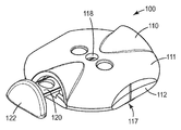
<도 1>
도 1은 본 개시내용의 한 실시예에 따른 마이크로니들 전달 시스템의 사시도이다.
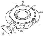
<도 2>
도 2는 도 1의 마이크로니들 전달 시스템의 사시도이다.
<도 3>
도 3은 도 1의 마이크로니들 전달 시스템의 분해도이다.
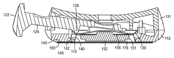
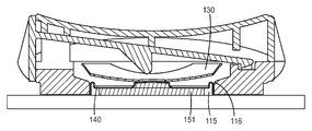
<도 4>
도 4는 도 1의 마이크로니들 전달 시스템의 횡단면도이다.
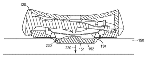
<도 5a 내지 도 5c>
도 5a 내지 도 5c는 선행 도면의 전달 시스템의 작동 시의 횡단면도이다.
<도 6>
도 6은 본 개시내용의 특정한 실시예에 따른 분기 스프링의 사시도이다.
<도 7>
도 7은 본 개시내용의 다른 한 양태에 따른 분기 스프링의 사시도이다.
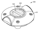
<도 8>
도 8은 본 개시내용의 다른 한 양태에 따른 마이크로니들 전달 시스템의 사시도이다.
<도 9>
도 9는 도 8의 전달 시스템의 횡단면도이다.
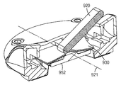
<도 10>
도 10은 본 개시내용의 다른 한 양태에 따른 마이크로니들 전달 시스템의 사시도이다.
<도 11>
도 11은 도 10의 전달 시스템의 횡단면도이다.
<도 12>
도 12는 본 개시내용의 또다른 한 양태에 따른 마이크로니들 전달 시스템의 사시도이다.
<도 13>
도 13은 도 12의 전달 시스템의 횡단면도이다.
<도 14>
도 14는 작동 시의 도 12의 전달 시스템을 묘사한다.
위에서 확인된 도면들이 본 발명의 몇몇 실시예를 설명하고 있지만, 설명에서 언급되는 바와 같이, 다른 실시예들도 고려된다. 모든 경우에서, 이 개시 내용은 본 발명을 제한하기 위한 것이 아니라, 설명하기 위해 나타낸 것이다. 본 발명의 원리의 범주 및 사상에 속하는 많은 다른 변형 및 실시예들이 당업자에 의해 창안될 수 있음을 이해하여야 한다.The present invention will be further described with reference to the drawings, in which corresponding reference numerals denote corresponding parts throughout the several views.
≪ 1 >
1 is a perspective view of a micro needle delivery system in accordance with one embodiment of the present disclosure;
2,
Figure 2 is a perspective view of the microneedle delivery system of Figure 1;
3,
3 is an exploded view of the microneedle delivery system of FIG.
<Fig. 4>
Figure 4 is a cross-sectional view of the microneedle delivery system of Figure 1;
5A to 5C,
Figures 5A-5C are transverse cross-sectional views of the delivery system of the prior art in operation.
6,
6 is a perspective view of a branch spring according to a particular embodiment of the present disclosure;
7,
7 is a perspective view of a branch spring according to another aspect of the present disclosure;
8,
8 is a perspective view of a microneedle delivery system in accordance with another aspect of the present disclosure.
9,
Figure 9 is a cross-sectional view of the delivery system of Figure 8;
<Fig. 10>
10 is a perspective view of a microneedle delivery system in accordance with another aspect of the present disclosure.
11)
11 is a cross-sectional view of the delivery system of Fig.
12,
12 is a perspective view of a microneedle delivery system in accordance with another aspect of the present disclosure;
13,
13 is a cross-sectional view of the delivery system of Fig.
<Fig. 14>
Figure 14 depicts the delivery system of Figure 12 during operation.
While the drawings identified above illustrate some embodiments of the invention, other embodiments are also contemplated, as noted in the description. In all cases, the disclosure is not intended to limit the invention but to illustrate it. It is to be understood that many other modifications and embodiments belonging to the scope and spirit of the principles of the invention may be devised by those skilled in the art.
전달 시스템의 한 실시예가 도 1 내지 도 4에 묘사되어 있다. 전달 시스템(100)은 장치 하우징(110)을 포함한다. 하우징(110)은 다른 요소들 중에서도 특히, 이용의 편의 및 환자 안락을 위해 비교적 낮은 높이(low profile) 및 작은 밑면(small footprint)를 제공하도록 자족적이고 간소하게 구성될 수 있다. 도 1 및 도 2에 예시된 실시예에서, 하우징(110)은 하부 하우징 부분(112) 및 짝을 이루는 상부 하우징 부분(111)을 포함할 수 있을 것이다. 대안적으로(묘사되지는 않았을지라도), 전달 시스템은 일체형 하우징을 포함할 수 있을 것이다. 상부 및 하부 하우징 부분(111 및 112)은 서로 스냅핏(snap-fit) 하는 것을 포함하지만 거기에 한정되지는 않는 어떤 적합한 수단으로든 서로 고정되거나, 또는 피봇(pivot), 마찰 죔쇠 끼워맞춤, 용접, 히트 스테이킹(heat-staking), 용매 접합, 및 메카니컬 패스너(mechanical fastener) 등에 의해 결합될 수 있을 것이다. 하우징(110)은 환자 및 종사자 취급의 편의를 위해 적합한 경량 재료로 만들어질 수 있을 것이다. 하우징(110)에 이용되는 재료는 플라스틱, 금속, 복합 재료, 및 그 조합을 포함할 수 있을 것이지만, 거기에 한정되지는 않는다. 예를 들어, 하우징(110)은 폴리프로필렌, 폴리부틸렌 테레프탈레이트, 폴리스티렌, 폴리에틸렌, 폴리테르마이드(polythermide), 폴리에틸렌 테레프탈레이트, 폴리스티렌, 폴리비닐 클로라이드, 폴리메틸메타크릴레이트, 아크릴로니트릴-부타디엔 스티렌, 폴리카보네이트, 및 그 블렌드와 같은 서모플라스틱으로 만들어질 수 있다. 다른 가능한 재료는 알루미늄, 스틸, 및 스테인리스 스틸과 같은 금속을 포함한다. 또한, 상부 하우징 부분(111)은 공동(116) 내의 요소들의 작동을 사용자가 쉽게 시각적으로 관찰하게 하는 창(118)을 포함할 수 있을 것이다. 추가적으로 또는 대안적으로, 상부 하우징 부분(111)은 마이크로니들 어레이의 부착을 사용자가 시각적으로 검사하게 하기 위해 투명한 재료를 포함할 수 있다.One embodiment of a delivery system is depicted in Figures 1-4. The
하우징(110)은 캐리어 조립체(150)를 수용하는 공동(116)을 포함한다. 캐리어 조립체(150)는 어레이 캐리어(151) 및 그 표면에 결합되는 마이크로니들 어레이(152)를 포함한다. 마이크로니들 어레이는 전달 시스템의 이용 중에 피부 표면(190)에 대체로 평행하게 배향된(도 5a에 묘사된 바와 같이) 주 평면(major plane)을 포함한다. 마이크로니들 어레이(152)는 하나 이상의 침 또는 침 모양의 구조체 뿐만 아니라 각질층을 뚫을 수 있는 다른 구조체를 포함할 수 있다. 마이크로니들은 높이가 전형적으로 900 미크론 미만, 흔히 500 미크론 미만이고, 때때로 높이가 300 미크론 미만이다. 마이크로니들은 전형적으로 높이가 20 미크론보다 크고, 흔히 높이가 50 미크론보다 크며, 때때로 높이가 125 미크론보다 크다. 저장 에너지 장치(130)는 캐리어 조립체(150)의 표면 근처의 공동(116)에 근접하거나 또는 내부에 수용된다. 저장 에너지 장치는 캐리어 조립체(150)의 일부와 직접 접촉할 수도 있다. 다른 실시예에서, 조립체(150)와 저장 에너지 장치(130) 사이의 거리는 다양해서 조립체(150)에 접촉하기 전에 저장 에너지 장치가 소정의 거리만큼 이동하게 할 수 있다.The
본 발명의 다양한 실시예에서 유용한 마이크로니들은 다음의 특허 및 특허 출원에 기술된 것들을 포함하지만 거기에 한정되지는 않는 다양한 구성 중 어느 것이든 포함할 수 있을 것이다. 마이크로니들을 위한 한 실시예는 미국 특허 출원 공보 US2003/0045837호에 개시된 구조체를 포함한다. 위에 기술한 특허 출원에 개시된 미세구조체는, 각각의 마이크로니들의 외부 표면에 형성된 하나 이상의 채널을 포함하는 테이퍼 구조를 갖는 마이크로니들의 형태이다. 마이크로니들은 한 방향으로 신장된 기부를 가질 수 있다. 신장된 기부를 가진 마이크로니들 내의 채널은 신장된 기부의 단부 중 하나로부터 마이크로니들의 팁을 향해 연장될 수 있다. 마이크로니들의 측면을 따라 형성된 채널은 마이크로니들의 팁에 도달하기 전에 임의로 종료될 수 있다. 마이크로니들 어레이는 또한 마이크로니들 어레이가 위치하는 기재의 표면 상에 형성된 도관 구조를 포함할 수 있다. 마이크로니들 내의 채널은 도관 구조와 유체 소통될 수 있다. 마이크로니들 장치를 위한 다른 한 실시예는 절두 테이퍼 형상 및 통제된 종횡비를 갖는 마이크로니들을 기술하는 함께 계류중인 미국 특허 출원 공보 US2005/0261631호에 개시된 구조체를 포함한다. 마이크로니들을 위한 또다른 한 실시예는 피부를 뚫기 위한 칼날 같은 극소융기를 기술하는 미국 특허 6,091,975호(대도나(Daddona) 등)에 개시된 구조체를 포함한다. 마이크로니들을 위한 또다른 한 실시예는 중공형 중앙 채널을 갖는 테이퍼 구조체를 기술하는 미국 특허 6,312,612호(쉐르만(Sherman) 등)에 개시된 구조체를 포함한다. 마이크로 어레이를 위한 또다른 한 실시예는 마이크로니들의 선단의 상면에서 하나 이상의 종방향 칼날을 갖는 중공형 마이크로니들을 기술하는 국제 공보 WO00/74766호(가르스테인(Garstein) 등)에 개시된 구조체를 포함한다.Microneedles useful in various embodiments of the present invention may include any of a variety of configurations, including but not limited to those described in the following patents and patent applications. One embodiment for a micro needle includes a structure disclosed in U. S. Patent Application Publication No. US2003 / 0045837. The microstructure disclosed in the above-mentioned patent application is in the form of a micro needle having a tapered structure including one or more channels formed on the outer surface of each micro needle. The micro needle can have a base extending in one direction. A channel in the microneedle with an elongated base may extend from one of the ends of the elongated base toward the tip of the microneedle. The channel formed along the side of the micro needle can be arbitrarily terminated before reaching the tip of the micro needle. The microneedle array may also include a conduit structure formed on the surface of the substrate on which the microneedle array is located. The channels in the micro needle can be in fluid communication with the conduit structure. Another embodiment for a micro needle device includes a structure disclosed in co-pending U. S. Patent Application Publication No. US2005 / 0261631, which describes a microneedle having a truncated tapered shape and a controlled aspect ratio. Another embodiment for a micro needle includes a structure disclosed in U. S. Patent No. 6,091, 975 (Daddona et al.) Which describes micro-bumps such as a blade for piercing skin. Another embodiment for a micro needle includes a structure disclosed in U.S. Patent No. 6,312,612 (Sherman et al.), Which describes a tapered structure with a hollow center channel. Another embodiment for a microarray includes a structure disclosed in International Publication WO00 / 74766 (Garstein et al.) Which describes hollow micro needles having one or more longitudinal blades at the top surface of the tip of a micro needle. do.
공동(116)은 상부 하우징(111) 및 하부 하우징(112) 둘 다의 협동에 의해 한정될 수 있거나, 또는 하부 하우징(112)에만 들어 있을 수 있을 것이다. 공동(116)의 최소 높이는 피부 표면에 도달하기 전의 마이크로니들 어레이(152)의 원하는 이동 거리 및 저장 에너지 장치의 이동 거리에 의해 적어도 부분적으로 판정된다. 따라서, 어떤 실시예에서의 공동(116)의 높이는 2 센티미터 이하일 수 있을 것이다. 다른 실시예에서, 공동(116)의 높이는 1 센티미터 이하일 수 있을 것이고, 다른 실시예에서는 8 밀리미터 이하일 수 있을 것이며, 또다른 실시예에서는 5 밀리미터 이하일 수 있을 것이다. 특정한 실시예에서, 공동의 높이는 1 밀리미터 이상이고, 다른 실시예에서는 2 밀리미터 이상이며, 다른 실시예에서는 5 밀리미터 이상이다. 높이가 1 밀리미터 미만인 공동들은 어레이가 각질층을 뚫기 위한 충분한 이동 거리를 허용하지 않을 수 있거나 및/또는 낮은 높이 장치에서 안전하거나 또는 바람직한 것보다 더 큰 힘을 어레이에 인가할 것을 요구할 수 있을 것이다.The
하부 하우징 부분(112)은 대체로 평면일 수 있는 기부(114)를 포함하고, 공동(116)에 대한 개구(115)를 한정한다. 기부(114)는 개구(115)를 적어도 부분적으로 감싸고 대체로 평면일 수도 있는 부착면(117)을 포함한다. 부착면(117)은 환자의 피부 표면에 대한 하우징(110)의 궁극적인 부착을 위해 접착제 층(160)을 포함할 수 있다. 접착제 층(160)은 접착제의 연속 코팅, 패턴화 코팅, 또는 개별 부분, 또는 그 조합일 수 있다. 특정한 실시예에서, 접착제의 제1 주 표면은 사용하기 전에 이형 라이너(170)에 결합될 수 있다(도 3 참조).The
하우징의 높이가 취급 및 작동의 편의를 위해 설계되는 것이 원해질 수 있을 것이다. 따라서, 하우징(110)의 높이는 3 센티미터 이하일 수 있을 것이다. 다른 실시예에서, 하우징의 높이는 1 센티미터 이하일 수 있을 것이고, 다른 실시예에서 5 밀리미터 이하일 수 있을 것이며, 다른 실시예에서 3 밀리미터 이하일 수 있을 것이다. 특정한 실시예에서, 하우징의 높이는 1.5 밀리미터 이상이고, 다른 실시예에서 2 밀리미터 이상이며, 다른 실시예에서 5 밀리미터 이상이다. 높이가 1.5 밀리미터 미만인 하우징은 어레이가 각질층을 뚫기 위한 충분한 이동 거리를 허용하지 않을 수 있고 취급하기 너무 곤란할 수 있을 것이다. 다른 한편으로는, 높이가 3 센티미터보다 큰 하우징은 다루기 불편할 수 있고 피부에 대한 접착상태를 유지하기가 곤란하다.It may be desired that the height of the housing is designed for ease of handling and operation. Thus, the height of the
이제 도 2 및 도 3을 보면, 전달 시스템(100)의 또다른 양태가 더 상세하게 도시된다. 특정한 실시예에서, 저장 에너지 장치(130)는 접착제, 패스너, 및 죔쇠 끼워맞춤 등을 포함하지만 거기에 한정되지는 않는 어떤 적합한 부착 수단이든지에 의해 하우징의 내부에 고정될 수 있다. 특정한 실시예에서, 저장 에너지 장치(130)의 주변부는 상부 하우징(111)과 하부 하우징(112) 사이에 들어 있고, 어떤 추가적 부착이든 없이 공동(116)에 근접하게 홈 또는 릿지 부분 상에 휴지될(rested) 수 있을 것이다. 저장 에너지 장치(130)는 어레이(152)의 부착면(117) 및 주 평면에 대체로 직교하는 방향으로 힘을 가하도록 작동 가능하다. 적합한 저장 에너지 장치는 돔형 스프링, 편향된 빔, 코일 스프링, 엽상 스프링, 및 프로펠런트 캐니스터(propellant canisters) 등을 포함하지만, 거기에 한정되지는 않는다. 대부분의 실시예에서, 저장 에너지 장치의 일부는 캐리어 조립체(150)에 인가력(application force)을 전달하기 위해 하우징 및/또는 공동 내에서 방해받지 않고 이동할 수 있다.Turning now to Figures 2 and 3, another aspect of the
저장 에너지 장치(130)는 캐리어 조립체(150)에 힘(즉, 인가 에너지)를 인가하기 위해 작동 가능하며, 그럼으로써 피부를 뚫기에 충분한 충격을 주기 전에 조립체의 적어도 일부를 소정의 속도까지 가속한다. 저장 에너지 장치를 작동시키기 위해 일관되고 예정된 양의 힘이 필요함으로써 작동 중에 일관된 양의 힘이 피부에 대해 수직하게 가해지게 되는 것이 바람직하다. 마이크로니들 어레이가 환자의 피부에 충격을 주기 전에 마이크로니들 어레이(152)는 전형적으로 약 2 내지 약 20 m/sec 사이의 범위의 충격 전 속도에 도달한다. 더 전형적으로, 어레이는 약 4 내지 약 15 m/sec 사이의 범위의 충격 전 속도로 환자의 피부를 타격한다. 특정한 바람직한 실시예에서는, 충격 시의 속도가 10 m/sec 초과로 일관적이다. 그러나, 충격 시 또는 그 후의 밑에 있는 신경 조직의 자극을 방지하거나 또는 저감시키기 위해 속도를 제한하는 것이 바람직할 수도 있다.The
특정한 실시예에서, 저장 에너지 장치(130)는 그것이 마이크로니들 어레이의 부착면 및/또는 주 평면에 대해 대체로 직교하는 방향으로 분기(즉, 단계적) 동작을 하도록 구성된다. 예를 들어, 그러한 실시예에서의 저장 에너지 장치는 도 6 및 도 7에 묘사된 바와 같이 돔형의 분기 스프링일 수 있다. 저장 에너지 장치는 도 9 및 도 11에 묘사된 바와 같이 복수의 분기 스프링을 포함할 수도 있다. 여기에서 이용되는 바로서, 분기 스프링은 예정된 힘이 스프링의 주 평면에 대해 수직하게 가해진 결과로서 형상 변화를 겪는 스프링이다. 여기에 추가로 기술된 방법을 이용하면, 사용중에 사용자가 전달 시스템에 편안하게 가할 수 있는 것보다 더 크거나 또는 실질적으로 더 큰 양의 에너지를 저장할 수 있는 분기 스프링을 제조하는 것이 가능하다.In a particular embodiment, the
그러한 분기 스프링의 한 실시예는 도 6에서 장착된 안정적 구성(즉, 외부에서의 에너지의 인가 전의 상태)으로 묘사되어 있다. 묘사된 스프링 외에, 다른 적합한 스프링은 접시형 와셔(Belleville washer) 및 돔형 스프링을 포함한다. 파동형 스프링(undulating spring)(330)은 대체로 원형인 중앙 부분 및 하나 이상의 다리(334)를 포함한다. 특정한 실시예에서, 스프링(330)은 중심에 근접한 개구(336)를 포함할 수 있다. 장착된 스프링(330)은 소정의 양의 위치 에너지를 저장하도록 설계된다. 예정된 양의 활성화 에너지가 스프링(330)의 제1 주 표면(332)에 전달될 때, 이 위치 에너지는 운동 에너지로 변환된다. 이것은 도 7에 묘사된 바와 같이 두개로 나뉘고 불안정해진 구성에 도달하는 스프링으로 귀결된다. 운동 에너지의 방출은 스프링의 주 평면에 대해 대체로 직교하는 방향(338)으로 발생하고, 그것은 스프링의 중심이 안정적 상태와 불안정해진 상태 사이에서 소정의 거리만큼 이동하는 것으로 귀결된다.One embodiment of such a branch spring is depicted in a stably configured configuration (i.e., a state prior to the application of external energy) in Fig. In addition to the depicted spring, other suitable springs include a dishwasher (Belleville washer) and a domed spring. The undulating
내부에 저장된 위치 에너지로 인해, 분기 스프링(330)은 분기를 유발하기 위해 필요한 에너지(즉, 활성화 에너지)보다 더 큰 에너지를 방출할 수 있을 것이다. 특정한 실시예에서, 운동 에너지(즉, 마이크로니들 어레이 또는 캐리어 조립체에 전달될 때의 인가 에너지)는 활성화 에너지의 적어도 두배이다. 특정한 실시예에서는, 인가 에너지는 활성화 에너지보다 4 배 더 크고, 다른 실시예에서는, 활성화 에너지보다 10 배 이상, 및 또다른 실시예에서는 활성화 에너지보다 20 배 이상 더 크다. 분기 스프링은 아마도 실질적으로 더 큰 에너지를 방출할 수 있을 것이므로, 충분한 인가 속도(application velocity)를 발생시키면서도 피부에 대해 수직하게 가해지는 힘의 크기는 최소화 될 수 있고, 캐리어 조립체에 가해지는 힘의 사용자마다의 가변성이 저감된다. 이 저감된 가변성은 더 일관되고 반복 가능한 마이크로니들 투과로 귀결될 수 있다.Due to the stored position energy inside the branching
본 개시내용에 따른 분기 스프링은, 예를 들어, 다른 방식으로는 분기하지 않는 돔형 스프링을, 주변을 지지한 상태에서, 중심에 대해 예정된 힘(즉, 부하)을 가함으로써 생성될 수 있을 것이다. 적합한 분기하지 않는 스프링은 미국, 콜로라도, 윈저 소재의 스냅트론 인코포레이티드(Snaptron Inc.)로부터 구입 가능한 스테인리스 스틸 돔형 스프링을 포함하지만 거기에 한정되지는 않는다. 스프링 표면에 가해지는 힘은 바람직하게는 스프링의 적어도 일부의 가소성 변형(plastic deformation)을 유발하기에 충분하다. 특정한 실시예에서는, 프레스(press) 또는 프로브(probe)가 스프링의 표면(332)에 대해 일정한 속도로 변위를 가한다. 프레스는 분기 후 원하는 힘이 가해질 때까지 계속해서 분기의 지점을 지나간다. 이 지점에서, 프로브는 이동을 정지하고 정해진 양의 유지 시간(hold time) 동안 제자리에 유지된다. "0(zero)"의 유지시간의 경우에는, 프레스는 원하는 굽힘력(bend force)에 도달한 후 즉시 후퇴하기 시작한다. 이론에 얽매이려는 것은 아니지만, 분기 후 가해진 부하 및 부하가 가해지는 시간은 둘 다 스프링을 활성화시키기 위해 필요한 에너지 및, 더 적은 정도로는, 분기 시에 방출되는 위치 에너지에 정으로 상관관계(positively correlated)를 이루는 것으로 보인다. 그러나, 소정의 시간 후, 유지 시간의 증가는 저장된 에너지의 주목할 만한 증가로 되지 않을 수 있을 것이다. 스프링의 활성화 후 가해지는 에너지는, 특히, 스프링의 재료, 재료의 두께, 및 돔의 기하학적 구조에 의해 추가로 영향을 받는다. 적어도 이러한 변수들을 잘 처리함으로써, 분기 스프링을 활성화시키기 위해 요구되는 에너지 및 캐리어 조립체에 가해지는 에너지 둘 다 원하는 마이크로니들 전달 시스템의 요구에 적합하게 맞춰질 수 있다.A branch spring in accordance with the present disclosure may be created, for example, by applying a predetermined force (i.e., load) to the center, with the dome-shaped spring not otherwise branching, while supporting the periphery. Suitable non-breaking springs include, but are not limited to, stainless steel domed springs available from Snaptron Inc. of Windsor, Colorado. The force applied to the spring surface is preferably sufficient to cause plastic deformation of at least a portion of the spring. In a particular embodiment, a press or probe applies a displacement at a constant speed to the
하우징(110)은 액추에이터(120)를 추가로 포함한다. 액추에이터(120)는 어플리케이터 장치를 형성하기 위해 저장 에너지 장치(130)와 협력한다. 액추에이터(120)는 상부 하우징 부분(111)에 형성된 액추에이터 개구(123)를 덮기에 적합한 손가락 맞물림 가능 부분(122)을 포함한다. 도 1 내지 도 5에 묘사된 실시예에서, 액추에이터는 손가락 맞물림 가능 부분(122)으로부터 개구(123)를 통해 공동(116) 내로 연장하는 연장된 아암 부분(124)을 추가로 포함한다. 아암 부분(124)은 쐐기(126) 또는 다른 돌출부를 포함할 수 있다. 액추에이터(120)는 부착면(117)에 대해 상대적인 각도로 하우징 내에서 이동 가능하다. 저장 에너지 장치(130)에 대해 상대적인 쐐기(126)의 움직임은 어레이(152)의 주 평면에 대해 대체로 직교하는 방향으로 힘을 가한다.The
다른 실시예에서, 액추에이터는 저장 에너지 장치(130)에 실제로 접촉하지 않을 수 있을 것이지만, 운동 에너지의 방출에 대한 장애를 제거할 수 있다. 예를 들어, 액추에이터는 저장 에너지 장치를 장전 위치(primed position)에서 유지하는 해제 가능한 고정 장치(releasable retaining device)에 맞물려 변형시킬 수 있을 것이다. 해제 가능한 고정 장치의 변형 또는 변위는 그 후 저장 에너지 장치가 그 안에 저장된 위치 에너지를 방출하게 할 수 있을 것이다.In other embodiments, the actuator may not actually contact the
도 3 및 도 4에 묘사된 바와 같이, 캐리어 조립체(150)는 중실형 마이크로니들 어레이(152), 어레이 캐리어(151), 및 가요성 막(140)을 포함한다. 마이크로니들 어레이(152)는 어떤 적합한 부착 수단에 의해서든 어레이 캐리어(151)의 제1 표면에 부착될 수 있다. 도 3에 도시된 바와 같이, 부착 수단은 접착제의 연속 코팅, 패턴화 코팅, 또는 개별 부분의 형태로 있을 수 있을 것인 접착제(157)이다. 한 양태에서, 접착제 부착은 영구적이지 않으며, 즉, 마이크로니들 어레이의 부착 후, 어레이의 전부 또는 일부가 잔류할지라도, 캐리어는 피부 표면으로부터 제거될 수 있을 것이다. 마이크로니들 장치(152)와 어레이 캐리어(151)를 연결하는 다른 적합한 부착 수단은, 스냅핏 연결, 후크 앤드 루프(hook and loop)(예를 들어, 벨크로(Velcro™)) 부착, 자기적 부착, 열 접합, 용접, 또는 이 기술분야에서 통상의 기술을 가진 자에게 알려진 어떤 다른 적합한 종래의 부착 방법이든 포함한다. 다른 실시예에서, 마이크로니들 어레이는 어레이 캐리어(151)의 필수적 부분(integral portion)으로서 형성 또는 성형될 수 있을 것이다.As depicted in Figures 3 and 4, the
도 2에 묘사된 마이크로니들 어레이(152)는 육각형 형상을 갖지만, 다수의 형상 및 크기 중 어느 것이든 본 발명의 응용 장치와 함께 이용하기에 적합하다.The
어레이 캐리어(151)의 적어도 일부는 비교적 경성이게 형성될 수 있다. 적합한 재료는 액정 중합체와 같은 중합체, 폴리프로필렌, 폴리부틸렌 테레프탈레이트, 폴리스티렌, 폴리에틸렌, 폴리테르마이드, 폴리에틸렌 테레프탈레이트, 폴리스티렌, 폴리비닐 클로라이드, 폴리메틸메타크릴레이트, 아크릴로니트릴-부타디엔 스티렌, 폴리카보네이트, 및 그 블렌드를 포함한다. 경성은 마이크로니들 어레이를 위한 지지를 가능하게 할 수 있으며, 인가 에너지의 전달을 보조할 수 있을 것이다. 금속, 세라믹, 및 이 기술분야에 숙련된 자들에게 자명할 것인 다른 재료들을 포함하는, 다른 재료들도 고려된다. 특정한 실시예에서, 어레이 캐리어는 마이크로니들 어레이의 마이크로니들과 동일한 재료로 이루어질 수 있다.At least a portion of the
캐리어 조립체(150)는 부착 메커니즘(158)을 통해 마이크로니들 어레이(152)의 반대쪽의 어레이 캐리어(151)의 표면에 결합되는 가요성 막(140)을 포함할 수 있다. 가요성 막(140)은 빌로우드 높이(142)를 갖는 챔버를 포함한다. 빌로우드 높이(142)는 바람직하게는 캐리어 조립체(150)가 공동(116) 내에 수용될 때 저장 에너지 장치(130)의 일부와 접촉하게 또는 거기에 매우 근접하게 유지되게 하는 것이다. 가요성 막(140)은 바람직하게는 저장 에너지 장치를 통해 캐리어 조립체(150)에 힘을 가하기 전에 빌로우드 높이(142)를 유지할 수 있다. 예를 들어, 막은 미국, 미네소타, 세인트폴 소재의 쓰리엠 컴퍼니(3M Company)로부터 구입 가능한 코트란(CoTran) 9701 폴리우레탄 필름으로 구성될 수 있다. 빌로우드 높이를 유지할 수 있는 다른 중합체성 필름은 막으로서 이용하기에 적합하기도 하다. 특정한 실시예에서, 가요성 막은 살균 가능하거나 및/또는 살균 장벽을 유지하는 재료를 포함한다.The
가요성 막(140)은 통풍되거나 또는 통풍되지 않을 수 있다. 전달 시스템(100)이 피부 표면에 배치될 때, 피부 표면, 접착제(160), 막/어레이 조립체, 및 아마도 하부 하우징(112)의 일부의 사이에 공기 챔버가 형성될 수 있을 것이다. 본 명세서에서 이용되는 바로서, 막은, 그것이 챔버의 밖으로의 유체의 흐름을 허용하기 위한 의도적인 개구 또는 채널을 포함할 때, "통풍되는" 것이다. 특정한 바람직한 실시예에서, 막의 적어도 일부는, 유체가 챔버의 밖으로 흐르게 하는 어떤 의도적인 수단도 포함하지 않는다는 점에서, 통풍되지 않는다. 통풍되지 않는 막은 놀랍게도 더 양호한 깊이의 피부 내로의 마이크로니들 투과를 가능하게 할 뿐만 아니라, 전체 어레이에 걸쳐 더 일관된 투과 레벨이 가능하게 할 수 있을 것이다. 또한, 통풍되지 않는 막은 캐리어 조립체가 사전 소독되고 경피 전달을 의도하는 약품이 제공되게 할 수 있을 것이다.The
캐리어 조립체(150)는 가요성 막(140)의 부착을 통해 공동(116) 내에 고정될 수 있을 것이다. 예를 들어, 소정의 길이의 가요성 막(140)이 부착 메커니즘(145)을 통해 개구(115)에 근접하게 하부 하우징(112)의 부분들에 고정될 수 있다. 추가적으로 또는 대안적으로, 챔버는 캐리어 조립체(150)가 하우징 내로 간단하게 압입될 수 있도록 공동(116)과의 죔쇠 끼워맞춤을 이룰 크기를 가질 수 있다.The
캐리어 조립체(150), 또는 그 일부는 저장 에너지 장치(130)에 결합되거나 또는 분리 가능하게 결합될 수도 있다. 예를 들어, 저장 에너지 장치(130)는 하나 이상의 개구를 포함할 수 있을 것이며, 어레이 캐리어(151)는 개구 내에 수용될 수 있는 하나 이상의 긴 돌출부를 포함할 수 있다. 그렇게 수용될 때, 돌출부는 저장 에너지 장치(130)에 리벳(rivet)으로 고정될 수 있을 것이다. 다른 실시예에서, 캐리어 조립체(150)는 접착제 또는 본 명세서에 기술된 다른 부착 수단에 의해 저장 에너지 장치(130)에 고정될 수 있을 것이다.The
캐리어 조립체가 스프링을 포함하는 저장 에너지 장치에 부착되거나 또는 분리 가능하게 부착되는 실시예에서는, 마이크로니들 어레이의 동작이 스프링의 동작에 연동된다. 인가 에너지의 활성화 및 전달 후(즉, 스프링의 저장된 위치 에너지의 방출 및 캐리어 조립체와의 그것의 후속적 접촉), 스프링 및 캐리어 조립체 둘 다 가해진 힘의 방향으로 피부 표면을 향해 협력적으로 이동할 것이다. 피부 표면에서의 조립체의 충격은 피부가 가해진 힘의 방향으로 이동하게 하기도 할 것이다. 활성화 후의 어떤 지점에서, 스프링은 최대 연장점에 도달하고 피부로부터 멀어지는 쪽으로 이동하기(즉, 되튀어나오기) 시작할 것이다. 그러나, 피부의 표면은 가해진 힘의 방향으로 계속 이동할 수 있을 것이다. 그것들은 스프링의 동작에 결합되므로, 마이크로니들은 투과를 정지시키거나 또는 피부 밖으로 뽑아내기도 하여, 더 적게 및/또는 더 많이 일관성 없는 투과 깊이를 초래할 수 있을 것이다.In embodiments in which the carrier assembly is attached to or detachably attached to a storage energy device comprising a spring, the operation of the microneedle array is interlocked with the operation of the spring. After activation and transfer of applied energy (i. E. Release of the stored potential energy of the spring and its subsequent contact with the carrier assembly), both the spring and carrier assembly will move cooperatively toward the skin surface in the direction of the applied force. The impact of the assembly on the surface of the skin may cause the skin to move in the direction of the applied force. At some point after activation, the spring will reach the maximum extension point and begin to move away from the skin (i. E., Bounce back). However, the surface of the skin will continue to move in the direction of the applied force. Since they are coupled to the action of the spring, the microneedles may stop transmission or pull them out of the skin, resulting in less and / or more inconsistent transmission depths.
본 개시내용의 한 예시적 실시예에서, 저장 에너지 장치(130)는 캐리어 조립체(150)에 부착되거나 또는 다른 방식으로 고정되지 않는다. 그래서, 피부에서의 충격에 뒤따라, 저장 에너지 장치(130)는 위쪽으로 자유롭게 되튀어나오며, 캐리어 조립체/마이크로니들 어레이의 이동에 다른 방식으로 영향을 미치지 않고 진동할 수 있을 것이다. 활성화 후, 캐리어 조립체(150)는 저장 에너지 장치(130)에 부착되지 않으므로, 그것은 피부의 동작으로 계속 자유롭게 전진하며; 저장 에너지 장치(130)의 되튀어나옴과 무관하다. 이 독립적 동작은 마이크로니들이 투과를 정지하거나 또는 피부 밖으로 빼내지는 경향을 저감시킬 수 있을 것이다. 마이크로니들의 증가된 깊이 및 더 일관된 투과는 각질층을 가로지르는 향상된 전달로 귀결될 수 있다.In one exemplary embodiment of the present disclosure, the
캐리어 조립체(150)는 가요성 막(140)을 이용하지 않고 저장 에너지 장치(130)에 부착하지 않은 채로 하우징(110) 또는 공동(116)에 결합될 수도 있다. 예를 들어, 어레이 캐리어는 내부 릿지 또는 홈 상에서 휴지하는 돌출부를 포함하여, 극소의 힘을 가할 때 캐리어 조립체가 방출되게 하는 죔쇠 끼워맞춤을 가능하게 할 수 있다. 본 명세서에 기술된 예시적 실시예 외에, 이 기술분야에서 숙련된 자는 저장 에너지 장치(130)에 결합함이 없이 캐리어 조립체를 하우징 내에 일시적으로 고정시키는 추가적 수단을 알 것이다.The
전달 시스템(100)은 완전히 조립되거나 및/또는 피부에 전달될 약품으로 코팅되어 종사자 또는 사용자에게 제공될 수 있을 것이다. 다른 실시예에서는, 캐리어 조립체는 하우징과 별도로 제공된다. 저장 에너지 장치가 수령 후 사용 직전에 장전되는 것이 가능할 수도 있을지라도, 특정한 바람직한 실시예에서는, 저장 에너지 장치가 장착된 구성으로 제공된다.The
본 개시내용은 환자의 피부 표면에 마이크로니들 어레이를 전달하기 위한 방법을 추가로 제공한다. 분리식 전달 시스템(100)을 이용하여 마이크로니들 어레이를 전달하기 위한 한 방법이 도 5a 내지 도 5c에 묘사되어 있다. 먼저 도 5a를 보면, 부착면(117)이 환자의 피부 표면(190)에 근접하게 배치된다. 배치되고 임의적으로는 접착제 층을 통해 고정될 때, 액추에이터(120)의 손가락 맞물림 가능 부분(122)에 힘이 가해질 수 있을 것이다. 이 힘은 전형적으로 어레이의 주 평면 및 부착면(117)에 대체로 평행한 방향(200)으로 가해진다. 가해진 힘은 저장 에너지 장치에 대해 상대적으로 쐐기(126)를 이동시키며, 저장 에너지 장치(130)의 주 평면에 직교하는 힘을 가하는 것으로 귀결된다. 이러한 힘의 인가는 저장 에너지 장치(130)에 대한 에너지(즉, 활성화 에너지)의 전달을 유발한다. 활성화 에너지가 예정된 한계를 초과할 때, 저장 에너지 장치는 그것의 위치 에너지를 방출하고, 장치(130)의 일부를 캐리어 조립체(150)를 향해 가속시킨다. 특정한 실시예에서, 저장 에너지 장치의 위치 에너지를 방출하기 위해 요구되는 힘은 15 N 이하이고, 어떤 실시예에서는 8 N 이하이며, 어떤 실시예에서는 5 N 이하이고, 또다른 실시예에서는 1 N이하이다. 소정의 상황에서는, 요구되는 힘이 2 N 이상이고 5 N 이하인 것이 바람직할 수 있을 것이다. 활성화 힘을 저감시키거나 또는 최소화하는 것이 유리할 수 있을 것이지만, 이 기술분야에서 숙련된 자들은 사용자가 전달 시스템을 이용할 준비가 되기 전에 저장 에너지 장치의 의도하지 않은 발사(firing)를 회피하기에 충분하게 활성화 힘이 커야 함을 알 것이다.The present disclosure further provides a method for delivering a microneedle array to a skin surface of a patient. One method for delivering a microneedle array using a
자신의 위치 에너지를 방출함에 있어서, 저장 에너지 장치(130)의 적어도 일부는 피부 표면의 방향으로 이동한다. 저장 에너지 장치(130)는 마이크로니들 어레이(152)의 주 평면에 대체로 직교하는 방향(220)으로 힘을 가하면서 캐리어 조립체(150)에 접촉할 것이다. 특정한 실시예에서, 저장 에너지 장치가 가하는 에너지는 0.3 J 이하이고, 어떤 실시예에서는 0.2 J 이하이며, 어떤 실시예에서는 0.15 J 이하이고, 또다른 실시예에서는 0.1 J 이하이다. 특정한 실시예에서, 저장 에너지 장치가 가하는 에너지는 0.006 J 이상이고, 어떤 실시예에서는 0.01 J 이상이며, 어떤 실시예에서는 적어도 0.05 J 이상이다. 소정의 상황에서는, 가해진 에너지가 0.013 J 이상이고 0.12 J 이하인 것이 바람직할 수 있을 것이다. 이러한 인가 에너지의 전달은 조립체가 궁극적으로는 개구(115)를 통해 나오게 하면서 막(140)을 포함하는 캐리어 조립체(150)를 피부 방향으로 가속한다. 특정한 실시예에서는, 인가 에너지가 활성화 에너지의 적어도 2배이고, 다른 상황에서는 활성화 에너지의 적어도 5 배, 다른 실시예에서는 활성화 에너지의 적어도 10 배, 또다른 실시예에서는 활성화 에너지의 적어도 20 배, 및 또다른 실시예에서는 활성화 에너지의 적어도 30 배이다.In releasing its own potential energy, at least a portion of the
도 5b는 마이크로니들 어레이(152)가 피부에 충격을 준 후 어떤 시점에서의 전달 시스템(100)을 묘사한다. 인가 에너지의 전달 후, 저장 에너지 장치(130)의 동작은 캐리어 조립체(150)의 동작보다 상대적으로 느리고, 그들 사이에 측정 가능한 갭(gap)(230)이 형성될 수 있을 것이다. 저장 에너지 장치, 캐리어 조립체, 및 피부의 물리적 특성에 따라, 이 갭은 저장 에너지 장치, 캐리어, 및 피부가 휴지하게 되기 전에 1회 이상 형성되고 폐쇄될 수 있을 것이다. 충격 후, 마이크로어레이, 피부, 및 막은 인가력의 방향(220)으로 계속 이동한다. 그러나, 동작이 분리되므로, 캐리어 조립체(150)는 피부의 최대 연장점까지 피부와 함께 자유롭게 이동한다.FIG. 5B depicts the
특정한 실시예에서, 막은 저장 에너지 장치(130)가 가하는 에너지로 인해 캐리어 조립체가 이동할 것인 것보다 더 큰 거리를 이동할 수 있다. 공동(116) 내에 수용되는 막(140)의 길이, 및 그 결과로서의 빌로우드 높이(142)는, 그에 따라 막(140)이 하우징(110)의 부착면(117)을 실질적으로 넘어서 연장하도록 설계될 수 있다.In certain embodiments, the membrane can travel a greater distance than the carrier assembly will travel due to the energy applied by the
궁극적으로, 피부 및 캐리어 조립체(150)는 되튀어나오기 시작하고 약해질 것이다. 도 5c에 묘사된 바와 같이, 캐리어 조립체는 마이크로니들을 제외하고는 그것의 실질적으로 어떤 부분도 개구(115)로 부터 빠져 나오지 않고 공동(116) 내에 휴지하게 될 수 있을 것이다. 묘사된 실시예에서, 막(140)은 그것의 본래의 빌로우드 높이(142)로 복귀하지 않고, "발사된(fired)" 저장 에너지 장치를 위해 공동(116) 내에 공간을 남기며, 마이크로니들이 원하는 투과 깊이에 잔류하게 한다. 다른 실시예에서는, 어레이 캐리어(151)의 적어도 일부는 하우징으로부터 빠져 나올 수 있다.Ultimately, the skin and
사용자가 본질적으로 피부의 표면에 평행한 방향을 갖는 힘(200)을 제공하므로, 전달 시스템(100)은 의미 있는 피부 돔(skin dome)을 생성하지 않고 피부를 실질적으로 연신하거나 또는 다른 방식으로 표면을 흐뜨러트리지 않은 채로 활성화 될 수 있다. 특정한 바람직한 실시예에서, 전달 시스템은 피부 돔을 생성하거나 또는 피부를 연신하지 않는다. 피부에 직교하는 방향으로의 작은 활성화 힘은 저장 에너지 장치를 활성시키기 위해 필요할 수 있을 것이지만, 피부 표면에 대해 수직으로 생성되는 힘은 본질적으로 하우징(110) 내에서 서로에 대해 반응된다. 따라서, 피부의 평면에 대해 수직인 방향으로 피부에 실제로 가해지는 힘은 0 또는 거의 0이다. 또한, 이 실시예에서의 피부의 평면에 평행한 방향으로 생성되는 힘은 쐐기(126)가 저장 에너지 장치의 표면을 가로질러 미끄러짐에 따라 거기에 적어도 실질적으로 전달된다. 그래서, 액추에이터의 평행한 미끄럼 동작의 효과는 활성화 동안에 사용자가 피부에 수직한 방향으로 장치를 미는 것을 아마도 좌절시킬 것이며, 부착의 일관성을 추가로 증가시킨다.The
또한, 고도의 기계적 이점으로 부착면에 대체로 평행한 방향으로 이동 가능한 액추에이터를 이용하는 것은, 사용자가 가하도록 요구되는 힘을 비교적 낮게 유지하면서, 저장 에너지 장치의 활성화 힘이 더 높은 레벨로 설정되게 할 수 있을 것이다. 큰 활성화 힘은 특정한 전달 시스템을 작동시킬 수 있는 환자 군을 한정할 수 있으므로, 이것이 특히 유용할 수 있을 것이다. 액추에이터의 평행한 동작은 충격 시의 어레이의 속도의 가변성을 추가로 저감시킬 수 있을 것이다.Furthermore, the use of actuators that are movable in a direction generally parallel to the attachment surface with a high degree of mechanical benefit may allow the activation force of the storage energy device to be set to a higher level while maintaining a relatively low force required by the user There will be. This may be particularly useful since large activation forces can limit the number of patients that can operate a particular delivery system. Parallel operation of the actuator may further reduce the variability of the speed of the array upon impact.
도 8 내지 도 11은 본 개시내용에 따른 전달 시스템, 특히 대안적 액추에이터를 특징으로 하는 것들의 추가적 구현을 묘사한다. 아래의 단락에서 설명하는 것을 제외하고는, 전달 시스템(800 및 900)은 위에 기술된 장치(100)와 실질적으로 동일하고, 그래서 유사한 양태의 기술이 반복될 필요가 없다.Figures 8-11 depict additional implementations of the delivery system according to this disclosure, particularly those featuring alternative actuators. Except as described in the following paragraphs, the
도 8 및 도 9에 묘사된 바와 같이, 전달 시스템(800)은 저장 에너지 장치(830) 위에 배치된 회전 가능한 액추에이터(820)를 특징으로 한다. 회전 가능한 액추에이터(820)는 어레이(852)의 주 평면에 대체로 직교하는 회전축(821)의 둘레로 회전한다. 본 명세서에 묘사되지 않은 다른 실시예에서는, 액추에이터(820)는 축(821)으로부터 편향된 각을 이루는 축의 둘레로 회전하도록 구성된다. 회전 가능한 액추에이터(820)는 헬리컬 나사(823) 및 그 외부 표면 상의 파악 가능한 릿지(822)를 포함한다. 상부 하우징(811)은 공동(816) 및 저장 에너지 장치(830) 위에 있는 개구(870)를 포함한다. 개구(870)는 액추에이터(820) 상의 헬리컬 나사에 대응하는 헬리컬 홈(873)을 포함하는 하나 이상의 측벽 부분을 갖는다. 축(821)의 둘레로의 액추에이터(820)의 회전은 맞물림 면(824)이 저장 에너지 장치(830)에 더 근접하게 한다. 액추에이터(820)는 그래서 맞물림 면(824)이 저장 에너지 장치(830)에 접촉하기까지 사용자에 의해 회전될 수 있을 것이며, 궁극적으로는 피부에 실질적으로 수직한 힘이 가해지지 않고 저장 에너지 장치(830)의 주 평면에 직교하는 예정된 활성화 힘의 인가로 귀결된다.As depicted in FIGS. 8 and 9, the
도 10 및 도 11은 상이한 회전 가능한 액추에이터를 특징으로 하는 마이크로니들 전달 시스템(900)을 묘사한다. 액추에이터(920)는 축(921)의 둘레로 회전 가능한 캠을 포함한다. 액추에이터(920)의 회전은 저장 에너지 장치(930)의 주 평면 및/또는 마이크로니들 어레이(952)에 직교하는 힘을 전달한다. 전달 시스템(800 및 900)은 동등한 양쪽에서의 힘이 장치 내에서 반응하여 활성화 동안에 피부에 수직하게 가해지는 아무런 힘도 없거나 또는 본질적으로 아무런 힘도 없게 하므로 위에 기술된 바와 같은 잠재적 이점을 제공할 수도 있을 것이다.Figures 10 and 11 depict a micro
전달 시스템의 한 대안적 실시예가 도 12 내지 도 14에 묘사되어 있다. 위에서 설명한 전달 시스템과 마찬가지로, 전달 시스템(1000)은 공동(1016)이 내부에 형성된 하우징(1010); 공동 내에 수용되거나 또는 거기에 근접한 저장 에너지 장치(1030); 및 어레이 캐리어(1051)에 결합되는 마이크로니들 어레이(1052)를 포함하는 캐리어 조립체를 포함한다. 상부 하우징 부분(1011)은 중앙 개구(1019) 내에 수용되는 부착 캡(1070)을 포함한다. 부착 캡(1070)은 분리 가능하거나 또는 다른 접착제, 죔쇠 끼워맞춤, 또는 이 기술분야에서 숙련된 자들에게 알려진 다른 수단을 통해 상부 하우징에 고정될 수 있다. 부착 캡을 위한 적합한 재료는 서모플라스틱 엘라스토머, 실리콘, 고무, 및 이 기술분야에서 숙련된 자에게 알려진 다른 재료를 포함한다.One alternative embodiment of the delivery system is depicted in Figures 12-14. As with the delivery system described above, the
부착 캡(1070)은 어레이 캐리어(1051)의 긴 아암 부분(1053)의 말단부를 수용한다. 특정한 실시예에서, 긴 아암 부분의 단부는 부착 캡(1070)이 없이 개구(1019) 내에 압입 끼워맞춤된다. 아암 부분(1053)은 개구를 통해 저장 에너지 장치(1030)의 중심 내로 연장하기도 한다. 특정한 실시예에서, 아암 부분(1053)은 그것이 저장 에너지 장치 개구(1032)의 주변과 맞물리지 않고 부착 캡(1070) 내에 압입 끼워맞춤될 수 있도록 설계된다 (즉, 개구의 크기가 아암 부분(1053)의 말단부의 크기보다 더 크다). 다른 실시예에서, 아암 부분(1053)의 기단부는 부착 캡의 필요를 없애고 개구(1032)와 죔쇠 끼워맞춤하도록 구성될 수 있을 것이다. 또다른 실시예에서, 부착 캡 및 캐리어와 저장 에너지 장치 사이의 죔쇠 끼워맞춤이 이용될 수 있다.The
액추에이터(1020)는 대체로 평면의 기부(1021)로부터 연장하는 하나 이상의 기둥(1022)을 포함한다. 기둥(1022)은 상부 하우징에 있는 개구(1013)를 통해 저장 에너지 장치(1030)에 근접하거나 또는 거기에 접촉하는 공동(1016) 내로 연장한다. 기부(1021)는 부착 캡(1070) 및/또는 아암 부분(1053)과 맞물리도록 설계된 중심 받침대(1024)를 포함하기도 한다. 액추에이터(1020)는 하우징(1010) 내에 이미 수용되거나 또는 별도의 콤포넌트로서 제공될 수 있을 것이다.
전달 시스템(1000)을 이용하는 하나의 잠재적 방법이 도 14에 묘사되어 있다. 사용자는 상부 하우징(1011)의 개구 내에 액추에이터(1020)를 배치한다. 그 후, 기부(1021) 및 부착면(1017)에 수직한 방향(1080)으로의 힘이 가해진다. 기부(1021)에 힘이 가해질 때, 중심 받침대(1024)는 부착 캡(1070)을 그것이 상부 하우징(1011)으로부터 분리되어 하우징(1010)과 독립적으로 자유롭게 이동하는 지점으로 아래로 민다. 그 후, 기둥(1022)은 저장 에너지 장치(1030)에 맞물려, 거기에 활성화 에너지를 전달한다. 기둥(1022)의 길이는 부착 캡(1070) (또는 아암 부분(1053))이 먼저 분리되고, 이어서 저장 에너지 장치(1030)에 에너지를 전달하도록 설계될 수 있다. 다른 실시예에서, 부착 캡(1070) 또는 아암 부분(1053)이 분리되고 저장 에너지 장치(1030)가 본질적으로 동시에 활성화된다. 또다른 실시예에서, 캐리어 조립체에 전달되는 인가 에너지는 부착 캡(1070)으로부터 아암 부분(1053)을 또는 하우징으로부터 부착 캡(1070)을 제거하기에 충분하다. 대안적으로, 부착 캡(1070)의 부분들은 받침대(1024)를 통해 압력을 인가할 때 팽창할 수 있어서, 부착 캡(1070)이 본질적으로 제자리에 유지된 채로 아암 부분(1053)을 분리시킨다.One potential method of using the
활성화 될 때, 저장 에너지 장치(1030)는 마이크로니들 어레이(1052)의 주 평면에 대체로 직교하는 방향(1080)으로 힘을 가하면서 캐리어 조립체에 접촉할 것이다. 이러한 인가 에너지의 전달은 조립체가 궁극적으로 하우징(1010)의 바닥의 개구를 통해 빠져나가게 하면서 캐리어 조립체를 피부의 방향으로 가속시킨다. 특정한 실시예에서, 중앙 받침대(1024)는 아암 부분(1053)을 피부를 향해 계속 밀 수 있을 것이며, 아마도 증가된 투과 깊이로 귀결된다.When activated, the
액추에이터(1020)의 기하학적 구조는 저장 에너지 장치가 작동됨과 동시에 기부(1021)의 바닥면이 상부 하우징의 상면과 거의 접촉하도록 조절될 수 있다. 그러한 실시예에서, 하우징(1010)이 피부로부터 되튀어나올 수 있는 총 거리는 액추에이터(1020)를 아래로 미는 사용자의 손가락의 존재로 인해 한정된다. 대안적으로, 액추에이터(1020)는 작동 시에 기부(1021)의 바닥면과 상부 하우징의 상부 사이에 간격을 제공하도록 설계될 수 있으며, 그것은 저장 에너지 장치(1030)가 그것의 위치 에너지를 방출함에 따라 하우징(1010)이 피부로부터 멀리 소정의 거리만큼 이동하게 할 것이다.The geometry of the
본 개시내용에서 이용하기에 적합한 마이크로니들 어레이는 경피 전달에 대한 변형으로 피부를 통해, 또는 예방 접종과 같은 피부 내 또는 국소 처치를 위해 피부에 대해 약물(어떤 약학적 약품 또는 약품들이든 포함)을 전달하기 위해 이용될 수 있을 것이다.A microneedle array suitable for use in the present disclosure may be any drug that can be administered to a skin (including any pharmaceutical agent or medicament) to the skin, either as a modification to transdermal delivery, through the skin, or as a skin or topical treatment, Lt; / RTI >
한 양태에서, 큰 분자량을 갖는 약물이 경피적으로 전달될 수 있을 것이다. 약물의 분자량을 증가시키는 것은 전형적으로 무지원 경피 전달(unassisted transdermal delivery)에서의 감소를 유발한다. 이 전달 시스템에서 이용하기에 적합한 마이크로니들 어레이는 보통은 수동적 경피 전달에 의해 전달하기 곤란한 큰 분자의 전달을 위해 유용성을 갖는다. 그러한 큰 분자의 예는 단백질, 펩타이드, 뉴클레오티드 배열, 단일클론성 항체, DNA 백신, 헤파린과 같은 다당류 및 세프트리악손과 같은 항생제를 포함한다.In one embodiment, drugs with large molecular weights may be transdermally delivered. Increasing the molecular weight of the drug typically results in a reduction in unassisted transdermal delivery. A microneedle array suitable for use in this delivery system has utility for the delivery of large molecules, which are usually difficult to deliver by passive transdermal delivery. Examples of such large molecules include proteins, peptides, nucleotide sequences, monoclonal antibodies, DNA vaccines, polysaccharides such as heparin, and antibiotics such as ceftriaxone.
다른 한 양태에서, 본 발명에서 이용하기에 적합한 마이크로니들 어레이는 다른 방식으로는 수동적 경피 전달에 의해 전달하기 곤란하거나 또는 불가능한 작은 분자의 경피 전달을 향상시키거나 또는 허용하기에 유용성을 가질 수 있을 것이다. 그러한 분자의 예는 염 형태; 비스포스포네이트, 바람직하게는 소듐 알렌드로네이트 또는 파메드로네이트와 같은 이온성 분자; 및 수동적 경피 전달에 도움이 되지 않는 물리화학적 특성을 갖는 분자를 포함한다.In another aspect, a microneedle array suitable for use in the present invention may have utility to enhance or permit transdermal delivery of small molecules that otherwise would be difficult or impossible to deliver by passive transdermal delivery . Examples of such molecules include, but are not limited to, a salt form; Ionic molecules such as bisphosphonates, preferably sodium alendronate or palmedronate; And molecules with physicochemical properties that do not contribute to passive transdermal delivery.
다른 한 양태에서는, 이 전달 시스템에서 이용하기에 적합한 마이크로니들 어레이는 피부학적 처치와 같은 피부에 대한 분자의 전달, 백신 전달을 향상시키기 위해, 또는 백신 보조제의 면역 반응을 향상시킴에 있어서 유용성을 가질 수 있을 것이다. 한 양태에서, 약물은 마이크로니들 어레이를 부착하기 전 또는 후에 피부에 도포될 수 있을 것이다(예를 들어, 피부 표면 상에 탈지면으로 발라지는 용액의 형태로 또는 피부 표면에 문질러 발라지는 크림으로서). 다른 한 양태에서는, 약물 또는 유체는 마이크로니들에 대해 직접적으로 도포될 수 있을 것이다.In another embodiment, a microneedle array suitable for use in this delivery system has utility in enhancing delivery of molecules to the skin, such as skin care, vaccine delivery, or enhancing the immune response of vaccine adjuvants It will be possible. In one embodiment, the drug may be applied to the skin either before or after attachment of the microneedle array (e.g., in the form of a solution sprinkled on the skin surface, or as a cream rubbing on the skin surface). In another embodiment, the drug or fluid may be applied directly to the microneedles.
다른 한 양태에서, 전달 시스템은 피부에서 극소융기를 생성하기 위해 이용될 수 있을 것이다.In another embodiment, the delivery system may be used to generate micro-bumps in the skin.
전달 시스템은, 즉시 전달을 위해, 즉 전달 시스템이 적용되고 적용 장소로부터 즉시 제거되는 경우, 또는 전달 시스템이 몇 분으로부터 1 주와 같이 긴 시간까지의 범위인 연장된 시간 동안 제자리에 남겨질 수 있을 것인 경우에 이용될 수 있을 것이다. 한 양태에서, 적용 및 즉시 제거 시 얻어질 수 있는 것보다 약물의 더 완전한 전달을 허용하기 위해 연장된 전달 시간은 1 내지 30 분일 수 있을 것이다. 다른 한 양태에서, 약물의 지속적 방출을 제공하기 위해 연장된 전달 시간은 4 시간 내지 1 주일 수 있을 것이다.The delivery system may be left in place for immediate delivery, i.e., when the delivery system is applied and immediately removed from the application site, or for a prolonged period of time ranging from a few minutes to a long time, such as one week And the like. In one embodiment, the extended delivery time may be from 1 to 30 minutes to allow more complete delivery of the drug than can be achieved with application and immediate removal. In another embodiment, the extended delivery time may be from 4 hours to 1 week to provide sustained release of the drug.
본 발명의 목적 및 이점은 하기의 실시예에 의해 추가로 예시되지만, 이들 실시예에서 언급된 특정 재료 및 그의 양뿐만 아니라 다른 조건 및 상세 사항도 본 발명을 부당하게 제한하는 것으로 해석되어서는 안 된다. 달리 표시되지 않으면, 모든 부 및 백분율은 중량 기준이다.The objects and advantages of the present invention are further illustrated by the following examples, but the specific materials and amounts thereof as well as other conditions and details mentioned in these examples should not be construed as unduly limiting the present invention . Unless otherwise indicated, all parts and percentages are by weight.
예Yes
두개의 상이한 완전히 조립된 전달 시스템이 평가되었다. 예 1의 경우에, 도 1 내지 도 5a 내지 도 5c에 기술되고 하나의 스프링을 갖는 설계의 분리식 전달 시스템이 이용되었다. 예 2의 경우에, 도 12 내지 도 14에 기술되고 세개의 스프링을 갖는 설계의 분리식 전달 시스템이 이용되었다.Two different fully assembled delivery systems were evaluated. In case of Example 1, a detachable delivery system of the design described in Figures 1 to 5A to 5C and having one spring was used. In the case of Example 2, a detachable delivery system of the design described in Figures 12 to 14 and having three springs was used.
전달 시스템의 하우징 콤포넌트는 스테레오리토그래픽 공정(stereolithographic process)을 이용하여 ACCURA60 플라스틱(미국, 사우스캐롤라이나, 록힐 소재의 3D 시스템즈(3D Systems))으로 제작되었다. 예 1의 외부의 하우징 크기는 34.0 mm (직경) 곱하기 9.4 mm (전고)이었다. 어레이를 위한 하우징에서의 개구는 직경이 16.0 mm이었다.The housing components of the delivery system were made with ACCURA60 plastic (3D Systems, Rock Hill, SC) using a stereolithographic process. The outer housing size of Example 1 was 34.0 mm (diameter) times 9.4 mm (full height). The opening in the housing for the array was 16.0 mm in diameter.
예 2의 외부의 하우징 크기는 27.0 mm (직경) 곱하기 8.0 mm (액추에이터 콤포넌트를 제외한 전고)이었다. 어레이를 위한 하우징에서의 개구는 직경이 14.0 mm이었다.The outer housing size in Example 2 was 27.0 mm (diameter) times 8.0 mm (height without actuator components). The opening in the housing for the array was 14.0 mm in diameter.
분기 스프링은 301 풀 하드 스테인리스 스틸(full-hard stainless steel)로 제조된 4지(four-legged)를 가진 돔형 스프링(미국, 콜로라도, 윈저 소재의 스냅트론)이었다. 도 6에 묘사된 바와 같이, 스프링은 연속 호로서 형성된 네개의 동등하게 이격되고 동등한 크기를 가진 컷아웃 섹션(cut-out section)을 갖는 원형 형상을 가졌다. 예 1의 경우에, 스프링의 직경(L1)은 20.2 mm이었다. 컷아웃에 의해 형성된 네개의 다리 구역의 각각은 다리(L2)의 외부 에지를 따라 측정된 바로서 4.4 mm이었다. 가장 좁은 지점에서 스프링의 중심을 가로지르고 통과하는 거리는 15.0 mm (L3)이었다. 3.2 mm 직경 구멍이 스프링의 중심에 배치되었다. 분기 및 조절 전 돔형 스프링의 높이는 2.3 mm이었다. 형성 전 돔형 스프링의 저장 두께(stock thickness)는 0.20 mm이었다.The branch spring was a four-legged domed spring made of 301 full-hard stainless steel (Snaptron from Windsor, Colorado, USA). As depicted in FIG. 6, the spring had a circular shape with four equally spaced and equal-sized cut-out sections formed as continuous arcs. In the case of Example 1, the diameter L1 of the spring was 20.2 mm. Each of the four leg sections formed by the cutout was 4.4 mm as measured along the outer edge of the leg L2. The distance through the center of the spring at the narrowest point was 15.0 mm (L3). A 3.2 mm diameter hole was placed in the center of the spring. The height of the domed spring before branching and control was 2.3 mm. The stock thickness of the domed spring before forming was 0.20 mm.
예 2의 경우에, 스프링의 직경 (L1)은 20.4 mm이었다. 컷아웃에 의해 형성된 네개의 다리 구역의 각각은 다리 (L2)의 외부 에지를 따라 측정된 바로서 3.9 mm이었다. 가장 좁은 지점에서 스프링의 중심을 가로지르고 통과하는 거리는 13.7 mm (L3)이었다. 3.2 mm 직경 구멍이 스프링의 중심에 배치되었다. 분기 및 조절 전 돔형 스프링의 높이는 1.8 mm이었다. 형성 전 돔형 스프링의 저장 두께는 0.18 mm이었다.In the case of Example 2, the diameter L1 of the spring was 20.4 mm. Each of the four leg sections formed by the cutout was 3.9 mm as measured along the outer edge of the leg L2. The distance through the center of the spring at the narrowest point was 13.7 mm (L3). A 3.2 mm diameter hole was placed in the center of the spring. The height of the domed spring before branching and control was 1.8 mm. The storage thickness of the domed spring before formation was 0.18 mm.
조립체 내에 스프링을 배치하기 전에, 예 1 및 예 2의 스프링은 분기되었고, 활성화 에너지 레벨은 다음의 스프링 조절 공정에 의해 설정되었다. 예 1의 단일의 스프링의 중심은 분기 후 3000g의 최대 변위 힘에 도달하기까지 분기점을 통해 0.1 mm/초의 속도로 그것의 휴지하는 기하학적 구조로부터 옮겨졌다. 스프링은 가해진 부하를 해제하기 전에 30 초 동안 최대 변위 힘으로 유지되었다. 1-스프링 시스템의 목표로 하는 저장된 위치 에너지는 0.059 J이었다. 예 2의 경우에, 각각의 스프링의 중심은 분기 후 1500 g의 최대 변위 힘에 도달하기까지 분기점을 통해 0.1 mm/초의 속도로 그것의 휴지하는 기하학적 구조로부터 옮겨졌다. 스프링의 각각은 가해진 부하를 해제하기 전에 30 초 동안 최대 변위 힘으로 유지되었다. 3-스프링 시스템의 목표로 하는 저장된 위치 에너지는 0.048 J이었다.Before placing the springs in the assembly, the springs of Example 1 and Example 2 were branched and the activation energy level was set by the following spring conditioning process. The center of a single spring of Example 1 was removed from its resting geometry at a rate of 0.1 mm / sec through a branch point until a maximum displacement force of 3000 g was reached after the branching. The spring was held at maximum displacement force for 30 seconds before releasing the applied load. The target stored energy of the 1-spring system was 0.059 J. In the case of Example 2, the center of each spring was shifted from its resting geometry at a rate of 0.1 mm / sec through the branch point until a maximum displacement force of 1500 g was reached after the branching. Each of the springs was maintained at the maximum displacement force for 30 seconds before releasing the applied load. The target stored energy of the 3-spring system was 0.048 J.
모든 예에서, 스프링 조절 절차는 350-400 g의 총 목표로 하는 활성화 힘을 생성하는 스프링 또는 스프링 세트를 제공하도록 설계되었다.In all examples, the spring adjustment procedure is designed to provide a spring or spring set that produces a total target activation force of 350-400 g.
예 1의 전달 시스템에서의 가요성 막은 직경이 약 25.2 mm이었고, 2 밀(mil)의 초기 필름 두께를 갖는 코트란 9701 폴리우레탄 필름(미국, 미네소타, 세인트폴 소재의 쓰리엠 컴퍼니(3M Company))으로 구성되었다. 빌로우드 막을 생성하기 위해 필름 연신 절차가 이용되었다. 쓰리엠 더블 코티드 메디컬 테이프 1513(3M Double Coated Medical Tape 1513)(미국, 미네소타, 세인트폴 소재의 쓰리엠 컴퍼니)의 연속 코팅을 이용하여 하부 하우징(조립되지 않은 장치의) 및 어레이 캐리어 둘 다에 대해 막이 부착되었다. 하부 하우징은 그것의 둘레에서 단순하게 지지되었고, 막 필름은 어레이 캐리어를 0.5 mm/초의 속도로 12 mm의 거리만큼 옮기고 30 초 동안 그것의 최대 변위를 유지함으로써 연신되었다. 전달 시스템의 조립체는 잔여 콤포넌트를 부착하고 부착된 어레이 캐리어를 갖는 빌로우드 막을 하우징의 공동 내에 배치함으로써 완성되었다.The flexible membrane in Example 1's delivery system was a Coatran 9701 polyurethane film (3M Company, St. Paul, Minn.) Having a diameter of about 25.2 mm and an initial film thickness of 2 mil, Respectively. A film stretching procedure was used to produce the bilobed film. A continuous coating of 3M Double Coated Medical Tape 1513 (3M Company, St. Paul, Minnesota, USA) was used to coat both the lower housing (of the unassembled device) and the array carrier Respectively. The lower housing was simply supported around it and the film film was stretched by moving the array carrier at a speed of 0.5 mm / sec by a distance of 12 mm and maintaining its maximum displacement for 30 seconds. The assembly of the delivery system was completed by attaching the remaining components and placing the bilobed film with the attached array carrier within the cavity of the housing.
예 1의 경우에, 마이크로니들 어레이는 LEXAN HPSIR-1125 폴리카보네이트 (PC) (미국, 매사추세츠, 피츠필드 소재의 지이 플라스틱스(GE Plastics))든 또는 VECTRA MT 1300 서모플라스틱 액정 중합체 (LCP) (미국, 켄터키, 플로렌스 소재의 티코나 엔지니어링 폴리머스(Ticona Engineering Polymers))든지를 이용하여 어레이 캐리어의 필수적 부분으로서 성형되었다. 마이크로니들 어레이는 약 500 미크론의 높이를 갖는 4면 피라미드 형상의 마이크로니들을 특징으로 하였다. 각각의 마이크로니들은 약 167 미크론의 기부 폭(base width) 및 약 10 미크론의 선단 폭(tip width)을 갖게 형성되었다. 마이크로니들은 약 550 미크론인 개별적 마이크로니들들 사이의 동등한 간격(선단으로부터 선단까지 측정된 바로서)을 갖는 약 471개의 마이크로니들들의 8변형 형상의 패턴으로 배향되었다. 어레이 캐리어는 13.4 mm의 직경을 갖는 원형 형상의 기부를 특징으로 하였다.In the case of Example 1, the microneedle array was either a LEXAN HPSIR-1125 polycarbonate (PC) (GE Plastics from Pittsfield, Massachusetts) or VECTRA MT 1300 thermoplastic liquid crystal polymer (LCP) (Ticona Engineering Polymers, Florence, KY), as an integral part of the array carrier. The microneedle array featured a four-sided pyramid-shaped micro needle having a height of about 500 microns. Each microneedle was formed to have a base width of about 167 microns and a tip width of about 10 microns. The micro needle was oriented in a pattern of 8 deformation shapes of about 471 microneedles with equivalent spacing (measured from tip to tip) between individual microneedles of about 550 microns. The array carrier was characterized by a base in the shape of a circle with a diameter of 13.4 mm.
예 2의 경우에, 마이크로니들 어레이는 LEXAN HPSIR-1125 폴리카보네이트 (PC)를 이용하여 어레이 캐리어의 필수적 부분으로서 성형되었다. PC 마이크로니들 어레이는 약 250 미크론의 높이를 갖는 4면 피라미드 형상의 마이크로니들을 특징으로 하였다. 각각의 마이크로니들은 약 83 미크론의 기부 폭 및 약 10 미크론의 선단 폭을 갖게 형성되었다. 마이크로니들은 약 275 미크론인 개별적 마이크로니들들 사이의 동등한 간격(선단으로부터 선단까지 측정된 바로서)을 갖는 약 1288개의 마이크로니들들의 8변형 형상의 패턴으로 배향되었다. 어레이 캐리어는 12.7 mm의 직경을 갖는 원형 형상의 기부를 특징으로 하였다. 예 2의 경우에, 어레이 캐리어는 직경이 2.8 mm이고 길이가 6.3 mm인 긴 아암을 포함하기도 하였다.In case 2, the microneedle array was molded as an integral part of the array carrier using LEXAN HPSIR-1125 polycarbonate (PC). The PC micro needle array was characterized by a four-sided pyramid shaped micro needle having a height of about 250 microns. Each microneedle was formed to have a base width of about 83 microns and a tip width of about 10 microns. The microneedles were oriented in a pattern of 8 deformation shapes of about 1288 microneedles with equivalent spacing (measured from tip to tip) between discrete micronees at about 275 microns. The array carrier was characterized by a circular shaped base with a diameter of 12.7 mm. In the case of Example 2, the array carrier also contained a long arm with a diameter of 2.8 mm and a length of 6.3 mm.
작동 후, 마이크로니들 어레이의 기부의 최종 휴지 위치는 예 1의 경우에 0.11 mm의 거리, 및 예 2의 경우에 0.08 mm의 거리만큼 하부 하우징의 기부의 너머로 연장되었다.After operation, the final rest position of the base of the micro needle array was extended beyond the base of the lower housing by a distance of 0.11 mm in the case of Example 1 and a distance of 0.08 mm in the case of Example 2.
마이크로니들 투과 깊이 연구(Microneedle Depth of Penetration Study)Microneedle Depth of Penetration Study
요크셔 잡종 미국 돼지(Yorkshire cross domestic pig)(미국, 미네소타, 기번 소재의 미드웨스트 리서치 스와인(Midwest Research Swine))의 피부 표면에 부착될 때의 어레이의 마이크로니들의 투과 깊이(depth of penetration)(DOP)를 판정하기 위한 연구가, 생체 내에서, 수행되었다. 부착하기 전에, 마이크로니들 어레이는 3단계 코팅 공정을 이용하여 로다민(Rhodamine) B로 코팅되었다. 단계 1에서, 코팅되지 않은 어레이가 50 μl의 1.0 mg/ml 폴리비닐 알코올 (80% 가수 분해된) (미국, 미주리, 세인트루이스 소재의 시그마 알드리치(Sigma-Aldrich)) 및 90%(중량/체적) 에틸 알코올 속의 67 μg/ml의 트윈(Tween®) 80 (미국, 미주리, 세인트루이스 소재의 시그마 알드리치)을 함유하는 용액으로 플러드 코팅(flood coated)되었다. 코팅된 어레이는 35℃에서 20 분 동안 건조되었다. 단계 2에서, 어레이는 60 μl의 33.3 mg/ml 황산 알루미늄 칼륨(aluminum potassium sulfate) 수용액(미국, 뉴저지, 리빙스턴 소재의 펜타 메뉴팩처링(Penta Manufacturing))으로 플러드 코팅된 후, 35℃에서 30 분 동안 건조되었다. 단계 3에서, 장전된 어레이는 60 μl의 0.08%(중량/체적) 로다민 B 수용액(미국, 미주리, 세인트루이스, 시그마 알드리치)으로 플러드 코팅된 후, 35℃에서 30 분 동안 건조되었다.The depth of penetration of the microneedles of the array when attached to the skin surface of a Yorkshire cross domestic pig (Midwest Research Swine, Gibson, Minn., USA) DOP) was performed in vivo . Prior to attachment, the microneedle array was coated with Rhodamine B using a three-step coating process. In step 1, the uncoated array was coated with 50 μl of 1.0 mg / ml polyvinyl alcohol (80% hydrolyzed) (Sigma-Aldrich, St. Louis, Missouri, USA) and 90% Was flood coated with a solution containing 67 [mu] g / ml Tween® 80 (Sigma Aldrich, St. Louis, Missouri, USA) in ethyl alcohol. The coated array was dried at 35 DEG C for 20 minutes. In step 2, the array was flood coated with 60 [mu] l of 33.3 mg / ml aqueous solution of aluminum potassium sulfate (Penta Manufacturing, Livingstone, NJ) Lt; / RTI > In
돼지의 햄 영역이 부착 위치로 선택되었다. 햄 영역은 먼저 전기 이발기로 털을 깍아내고, 이어어 면도기 및 면도 크림으로 면도되었다. 그 후, 햄을 탈이온수로 씻고 70/30 아이소프로판올 물로 닦아내었다. 동물은 아이소플루레인 기체로 마취되고 실험 내내 마취 상태로 유지되었다.The ham area of the pig was selected as the attachment site. The ham area was first shaved off with an electric hair clipper, followed by a shaver and a shaving cream. After that, the ham was washed with deionized water and wiped with 70/30 isopropanol water. Animals were anesthetized with isoflurane gas and maintained in anesthesia throughout the experiment.
예 1에서 기술된 바와 같이 완전히 조립된 전달 시스템이 쓰리엠 더블 코티드 메디컬 테이프 1513으로 돼지의 햄 영역의 피부에 부착되었다. 전달 시스템이 작동되었고, 15 분 동안 동물에서 유지된 후, 제거되었다.A fully assembled delivery system, as described in Example 1, was attached to the skin of the ham region of the pig with a 3 double-coated medical tape 1513. The delivery system was activated, maintained in the animal for 15 minutes, and then removed.
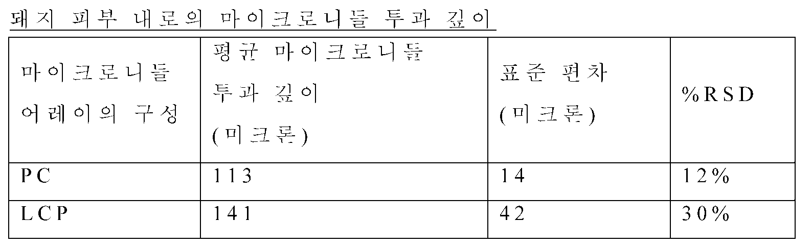
돼지 피부 내로의 투과 깊이는 마이크로니들의 선단으로부터 피부 내에 박은 후 마이크로니들로부터 로다민 B 코팅이 닦여지거나 또는 용해된 곳까지의 거리를 측정함으로써 간접적으로 판정되었다. 측정은 100X 배율의 Nikon LV-100 현미경(미국, 뉴욕, 멜빌 소재의 니콘 인스트루먼츠(Nikon Instruments))을 이용하고 이미지 프로 플러스(Image Pro® Plus) 디지털 이미지 분석 소프트웨어(미국, 메릴랜드, 베데스다 소재의 미디어 사이버네틱스(Media Cybernetics))에 의해 수행되었다. 각각의 마이크로니들 어레이 유형(PC 또는 LCP)마다, 세 마리의 동물이 시험되었다. 각각의 어레이로부터 72개 마이크로니들 서브 세트를 샘플링하여 평균 DOP가 판정되었다. 각각의 어레이 패턴은 네개의 사분원으로 분할되었고, 각각의 사분원으로부터 비교적 동등한 수의 마이크로니들들이 샘플링되었다. 표 1에서, 결과는 마이크로니들 DOP 연구로부터 보고되었다.The penetration depth into the pig skin was determined indirectly by measuring the distance to where the rhodamine B coating was wiped or dissolved from the microneedles after being stuck into the skin from the tip of the microneedle. The measurement was carried out using a 100X magnification Nikon LV-100 microscope (Nikon Instruments, Melville, NY) and Image Pro® Plus digital image analysis software (Media of Bethesda, Cybernetics (Media Cybernetics). For each microneedle array type (PC or LCP), three animals were tested. An average DOP was determined by sampling a subset of 72 micro-needles from each array. Each array pattern was divided into four quadrants, and a comparable number of microneedles from each quadrant were sampled. In Table 1, the results were reported from a micro needle DOP study.
파상풍 변독소 면역 연구(Tetanus Toxoid Immunization Study)Tetanus Toxoid Immunization Study
예 2에 기술된 바와 같은 완전히 조립된 마이크로니들 어레이 전달 시스템이 파상풍 변독소 면역 연구에 이용되었다.A fully assembled micro needle array delivery system as described in Example 2 was used for the tetanus toxin immunity study.
위에 기술된 마이크로니들 어레이는 파상풍 변독소 (덴마크, 코펜하겐 소재의 스테튼스 세럼 인스티튜트(Statens Serum Institute)), 수크로스 (30%), 하이드록시에틸 셀룰로오스 (1%), 및 PBS 버퍼를 함유하는 조제물로 딥코팅되었다(미국 특허 출원 공보 US2008/0051699호(최(Choi), 등)에서 제안된 딥코팅 절차). 코팅된 어레이는 오븐 내에서 30 분 동안 35℃에서 건조되었다. 건조된 어레이는 포일을 붙인 습기 장벽을 갖는 주머니 내에 밀봉되었고, 5 ± 3℃에서 저장되었다. 조립체 캐리어에 부착하기 전에, 어레이는 환경 조건(21℃ 및 45% 상대 습도)에 대한 평형이 유지되었다. 코팅된 어레이는 동물 실험을 시작하기 전 3 시간 이하인 한 시점에서 쓰리엠 더블 코티드 메디컬 테이프 1513을 이용하여 전달 시스템의 어레이 캐리어에 부착되었다.The above described microneedle arrays were incubated with a preparation containing a tetanus toxin (Statens Serum Institute, Copenhagen, Denmark), sucrose (30%), hydroxyethylcellulose (1% (Dip coating procedure proposed in U.S. Patent Application Publication No. US2008 / 0051699 (Choi, et al.)). The coated array was dried at 35 < 0 > C for 30 minutes in an oven. The dried array was sealed in a bag with a foil-laden moisture barrier and stored at 5 3C. Prior to attachment to the assembly carrier, the array was maintained at equilibrium for the environmental conditions (21 < 0 > C and 45% relative humidity). The coated array was attached to the array carrier of the delivery system using a 3 Double-Coated Medical Tape 1513 at a point no more than 3 hours before starting the animal experiment.
코팅된 마이크로니들 어레이 상의 파상풍 변독소 함량 (마이크로그램 (mcg)으로)을 판정하기 위해 역상 HPLC 분석 평가가 이용되었다. 동물에게 전달된 파상풍 변독소의 투여량은 어레이 상의 초기 파상풍 변독소 함량과 동물에게 투여한 후의 어레이 상의 잔류 파상풍 변독소 사이의 차이를 측정함으로써 계산되었다.Reversed phase HPLC assay evaluation was used to determine the tetanus toxin content (in micrograms (mcg)) on the coated micro needle array. The dose of the tetanus toxin delivered to the animal was calculated by measuring the difference between the initial tetanus toxin content on the array and the residual tetanus toxin on the array after administration to the animal.
수컷, 무모 기니 피그(미국, 매사추세츠, 윌밍턴 소재의 찰스 리버 레버러토리즈(Charles River Laboratories)로부터 획득된)는 연구 초기에 대략적으로 9개월 나이이었고 800 내지 1000 g 사이의 체중을 가졌다. 연구의 1일차 및 28일차에 총 5마리의 동물에 투여되었다. 예 2의 완전히 조립된 전달 시스템을 쓰리엠 더블 코티드 메디컬 테이프 1513에 의해 동물의 복부 상의 피부에 부착함으로써 마취된 동물들에 투여되었다. 전달 시스템은 작동되었고 5 분 동안 동물의 피부 상에 유지되었다. 어레이 상에 코팅된 파상풍 변독소의 양의 평균값(mcg/어레이) 및 각각의 동물에 주어진 투여량의 계산된 평균(mcg/동물)이 표 2에 보고되어 있다. 어레이 상에 코팅된 대략적으로 50%의 파상풍 변독소가 동물에게 전달되었다.Males, guinea pigs (obtained from Charles River Laboratories, Wilmington, Mass., USA) were approximately 9 months old at the beginning of the study and weighed between 800 and 1000 g. On the 1st and 28th day of the study, a total of 5 animals were administered. The fully assembled delivery system of Example 2 was administered to anesthetized animals by attaching it to the skin on the abdomen of an animal by a 3 double-coated medical tape 1513. [ The delivery system was activated and maintained on the skin of the animal for 5 minutes. The mean (mcg / array) of the amounts of tetanus toxin coated on the array and the calculated average of the dose given to each animal (mcg / animal) are reported in Table 2. Approximately 50% of the tetanus toxin coated on the array was delivered to the animal.
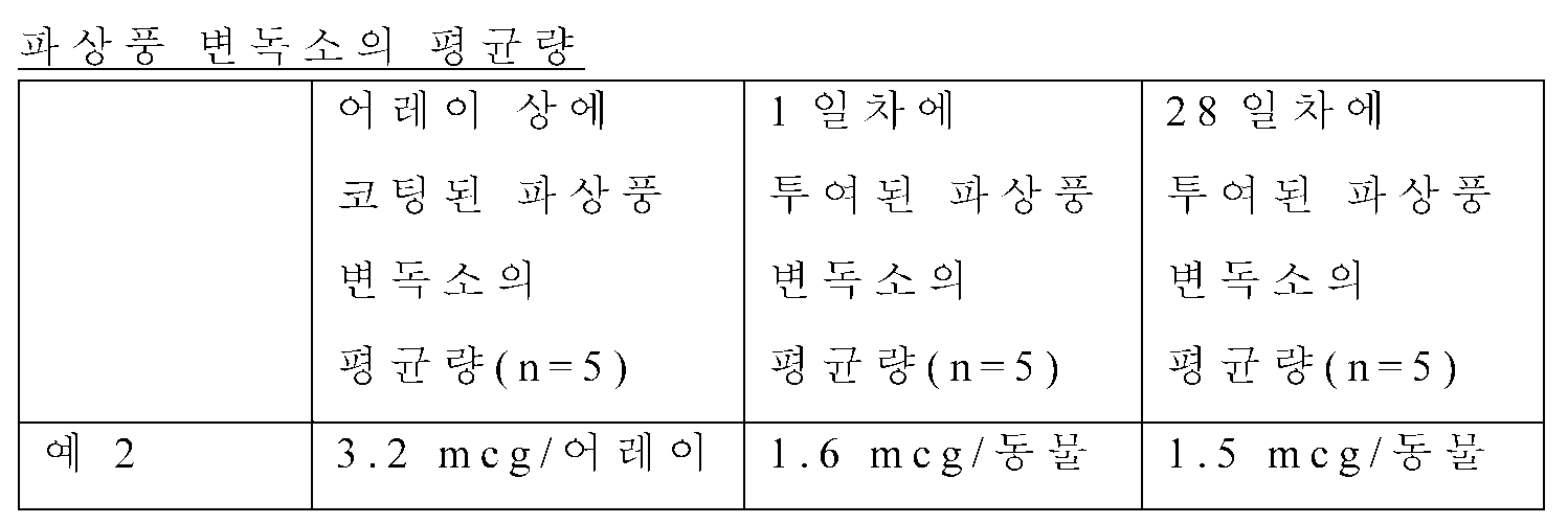
연구의 28일차 및 56일차에 마취된 동물 상에서 혈액 채취가 수행되었다. 혈청이 분리되었고, 중간 티터링(mid-point tittering) ELISA 분석 평가를 이용하여 항파상풍 변독소 IgG를 위해 분석되었다. 생체 표준 및 제어를 위한 국립 연구소(the National Institute for Biological Standards and Control)(잉글랜드, 하트퍼드셔)로부터 획득된 NIBSC Code 98/572 디프테리아 및 파상풍 항독소 기니 피그 혈청을 이용하여 분석 평가가 표준화되었다. 항파상풍 변독소 IgG 티터는 0.2 IU/mL의 측정된 IgG 레벨과 동등한 20 ELISA 단위에 의한 ELISA 단위로 표현되었다. 20 ELISA 단위보다 더 큰 IgG 티터를 갖는 동물은 시로컨버트(seroconverted)될 것으로 판정되었다. 표 3에서, 연구의 28일차 및 56일차에서의 항파상풍 변독소 IgG 티터 값(titer value)은 5마리의 동물의 각각마다 보고되었다. 28일차(1회 투여 후)에, 5마리 중 3마리의 동물이 시로컨버트되었다. 56일차(2회 투여 후)에, 5마리 동물 모두 시로컨버트되었다.Blood sampling was performed on animals anesthetized at day 28 and day 56 of the study. Serum was isolated and analyzed for anti-tetanus toxin IgG using mid-point tittering ELISA assay. Analytical evaluation was standardized using NIBSC Code 98/572 diphtheria and tetanus antitoxin guinea pig serum obtained from the National Institute for Biological Standards and Control (Hertfordshire, England). The anti-tetanus toxin IgG titers were expressed in ELISA units by 20 ELISA units equivalent to a measured IgG level of 0.2 IU / mL. Animals with IgG titer greater than 20 ELISA units were determined to be seroconverted. In Table 3, the anti-tetanus toxin IgG titer values at the 28th and 56th day of the study were reported for each of five animals. At day 28 (after one dose), 3 of 5 animals were converted to time. At day 56 (after 2 doses), all 5 animals were converted to time.
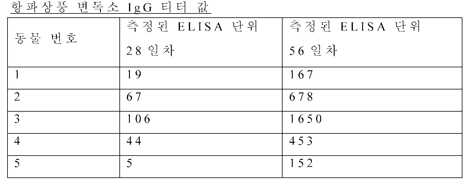
본 명세서에 인용된 특허, 특허 문헌, 및 공보의 전체 개시 내용은 각각이 개별적으로 포함된 것처럼 전체적으로 본 명세서에 참조로서 포함된다. 본 발명의 범주 및 취지를 벗어나지 않고도 본 발명에 대한 다양한 변형 및 변경이 당업자에게 명백하게 될 것이다. 본 발명은 본 명세서에 개시된 예시적 실시 형태 및 실시예로 부당하게 제한하고자 하는 것이 아니며, 그러한 실시예 및 실시 형태는 단지 예시의 목적으로 제시되고, 본 발명의 범주는 이하의 본 명세서에 개시된 특허청구범위로만 제한하고자 함을 이해하여야 한다.The entire disclosures of patents, patent documents, and publications cited in this specification are incorporated herein by reference in their entirety as if each were individually incorporated. Various changes and modifications to the present invention will become apparent to those skilled in the art without departing from the scope and spirit of the present invention. It is not intended that the invention be unduly limited to the illustrative embodiments and examples disclosed herein, but such embodiments and embodiments are presented by way of example only, and the scope of the present invention is not limited to the patents But is intended to be limited only by the scope of the claims.
Claims (30)
내부에 공동을 갖고 어플리케이터 장치를 포함하는 하우징; 및
중실형(solid) 마이크로니들 어레이를 포함하는 캐리어 조립체를 포함하고, 상기 캐리어 조립체의 일부는 상기 공동에 근접하게 상기 하우징에 부착되고 상기 어플리케이터의 일부와 접촉하며; 상기 캐리어 조립체든 상기 어레이든 상기 어플리케이터 장치에 부착되지 않는, 통합된 시스템.An integrated system for delivering a microneedle array, the system comprising:
A housing having a cavity therein and including an applicator device; And
A carrier assembly including a solid microneedle array, wherein a portion of the carrier assembly is attached to the housing proximate the cavity and contacts a portion of the applicator; Wherein the carrier assembly or the array is not attached to the applicator device.
제1항의 시스템을 제공하는 단계;
상기 피부 표면에 대해 상기 하우징을 배치하는 단계; 및
어플리케이터 장치를 통해 캐리어에 활성화 에너지를 전달함으로써 상기 피부를 향해 상기 어레이 및 캐리어를 구동하는 단계를 포함하는, 방법.A method of delivering a micro needle array to the surface of a skin, the method comprising:
Providing the system of claim 1;
Disposing the housing against the skin surface; And
And driving the array and carrier towards the skin by transferring activation energy to the carrier through the applicator device.
막, 마이크로니들 어레이 캐리어, 및 하우징을 제공하는 단계;
상기 막에 소정의 빌로우드 높이를 갖는 리세스(recess)를 생성하는 단계;
캐리어 조립체를 생성하기 위해 상기 어레이 캐리어를 상기 리세스 내의 상기 막에 부착하는 단계; 및
상기 캐리어 조립체를 상기 하우징에 부착하는 단계를 포함하는, 방법.A method of assembling an integrated system for delivery of a microneedle array, the method comprising:
Providing a membrane, a microneedle array carrier, and a housing;
Creating a recess in the film having a predetermined bellows height;
Attaching the array carrier to the membrane in the recess to create a carrier assembly; And
And attaching the carrier assembly to the housing.
내부에 공동을 갖고 어플리케이터 장치를 포함하는 하우징; 및 중실형 마이크로니들 어레이를 포함하는 캐리어 조립체 - 상기 캐리어 조립체의 일부는 상기 공동에 근접하게 상기 하우징에 부착되고, 상기 캐리어 조립체든 상기 어레이든 상기 어플리케이터 장치에 부착되지 않음 - 를 포함하는 전달 시스템을 제공하는 단계;
상기 피부 표면에 대해 상기 하우징을 배치하는 단계; 및
상기 어플리케이터 장치를 통해 상기 캐리어 조립체에 활성화 에너지를 전달함으로써 상기 피부를 향해 상기 어레이 및 캐리어를 구동하는 단계를 포함하며,- 전달 시 상기 환자의 피부가 수직으로 받는 힘이 0 또는 거의 0인, 방법.A method of delivering a micro needle array to the surface of said skin, said method comprising:
A housing having a cavity therein and including an applicator device; And a carrier assembly including a solid-state microneedle array, wherein a portion of the carrier assembly is attached to the housing proximate the cavity, and wherein the carrier assembly or the array is not attached to the applicator device. ;
Disposing the housing against the skin surface; And
And driving the array and carrier towards the skin by transferring activation energy to the carrier assembly through the applicator device, wherein the force of the patient's skin vertically received at delivery is zero or substantially zero .
Applications Claiming Priority (3)
| Application Number | Priority Date | Filing Date | Title |
|---|---|---|---|
| US201161546340P | 2011-10-12 | 2011-10-12 | |
| US61/546,340 | 2011-10-12 | ||
| PCT/US2012/059273 WO2013055638A1 (en) | 2011-10-12 | 2012-10-09 | Integrated microneedle array delivery system |
Publications (2)
| Publication Number | Publication Date |
|---|---|
| KR20140077952A true KR20140077952A (en) | 2014-06-24 |
| KR102022574B1 KR102022574B1 (en) | 2019-09-18 |
Family
ID=48082330
Family Applications (1)
| Application Number | Title | Priority Date | Filing Date |
|---|---|---|---|
| KR1020147012297A Active KR102022574B1 (en) | 2011-10-12 | 2012-10-09 | Integrated microneedle array delivery system |
Country Status (9)
| Country | Link |
|---|---|
| US (1) | US10010707B2 (en) |
| EP (1) | EP2766066B8 (en) |
| JP (1) | JP6126105B2 (en) |
| KR (1) | KR102022574B1 (en) |
| CN (1) | CN103874518A (en) |
| AU (1) | AU2012323392A1 (en) |
| CA (1) | CA2851606C (en) |
| IN (1) | IN2014CN02643A (en) |
| WO (1) | WO2013055638A1 (en) |
Cited By (2)
| Publication number | Priority date | Publication date | Assignee | Title |
|---|---|---|---|---|
| KR20240048875A (en) | 2022-10-07 | 2024-04-16 | 한미약품 주식회사 | Soluble microneedle array and fabrication method thereof |
| KR20240100685A (en) | 2022-12-23 | 2024-07-02 | 한미약품 주식회사 | Microneedle array and fabrication method thereof |
Families Citing this family (29)
| Publication number | Priority date | Publication date | Assignee | Title |
|---|---|---|---|---|
| WO2013036602A1 (en) | 2011-09-07 | 2013-03-14 | 3M Innovative Properties Company | Delivery system for hollow microneedle arrays |
| CN104736192B (en) | 2012-10-10 | 2018-02-13 | 3M创新有限公司 | APPLICATION DEVICES AND METHODS FOR APPLYING MICRONEEDLE DEVICES TO SKIN |
| WO2014058746A1 (en) | 2012-10-10 | 2014-04-17 | 3M Innovative Properties Company | Force-controlled applicator for applying a microneedle device to skin |
| EP2919849B1 (en) | 2012-11-16 | 2021-01-06 | Kindeva Drug Delivery L.P. | Force-controlled applicator for applying a microneedle device to skin |
| WO2016162449A1 (en) * | 2015-04-07 | 2016-10-13 | Lts Lohmann Therapie-Systeme Ag | Microneedle system for administering liquid formulations |
| AU2017258749B2 (en) * | 2016-04-29 | 2022-06-16 | Vivasor, Inc. | Microneedle array assembly, drug delivery device and method for administering liquid across a broad area at low pressure |
| CN121588347A (en) | 2016-12-16 | 2026-03-03 | 索伦托治疗有限公司 | Application mechanism for fluid delivery device and method of use thereof |
| EP4473998A3 (en) * | 2017-08-04 | 2025-02-26 | Vaxxas Pty Limited | Compact high mechanical energy storage and low trigger force actuator for the delivery of microprojection array patches (map) |
| DE102017117784A1 (en) * | 2017-08-04 | 2019-02-07 | Lts Lohmann Therapie-Systeme Ag | Applicator system comprising a microneedle array having a drug for wound healing |
| JP7319979B2 (en) * | 2017-12-19 | 2023-08-02 | キンデーバ ドラッグ デリバリー リミティド パートナーシップ | microarray applicator |
| WO2019166572A1 (en) | 2018-02-28 | 2019-09-06 | Pharming Intellectual Property B.V. | Pharmaceutical system for transdermal administration of a c1 -esterase inhibitor |
| DE102019200557A1 (en) * | 2019-01-17 | 2020-07-23 | Lts Lohmann Therapie-Systeme Ag | Applicator |
| DE102019200561A1 (en) * | 2019-01-17 | 2020-07-23 | Lts Lohmann Therapie-Systeme Ag | carrier |
| KR102368260B1 (en) * | 2020-01-09 | 2022-03-02 | 연세대학교 산학협력단 | Microneedle applicator |
| JP2023523952A (en) | 2020-04-28 | 2023-06-08 | ティコナ・エルエルシー | microneedle assembly |
| JP7737398B2 (en) * | 2020-04-28 | 2025-09-10 | ティコナ・エルエルシー | Microneedle Assembly |
| US11389632B2 (en) | 2020-12-21 | 2022-07-19 | Mediccene Inc. | Intradermal drug delivery device |
| US12611530B2 (en) | 2020-12-21 | 2026-04-28 | Mediccene Inc. | Intradermal drug delivery device |
| US12053284B2 (en) | 2021-11-08 | 2024-08-06 | Satio, Inc. | Dermal patch for collecting a physiological sample |
| US11877848B2 (en) | 2021-11-08 | 2024-01-23 | Satio, Inc. | Dermal patch for collecting a physiological sample |
| US12178979B2 (en) | 2021-10-13 | 2024-12-31 | Satio, Inc. | Dermal patch for delivering a pharmaceutical |
| US12048543B2 (en) | 2021-11-08 | 2024-07-30 | Satio, Inc. | Dermal patch for collecting a physiological sample with removable vial |
| US11964121B2 (en) | 2021-10-13 | 2024-04-23 | Satio, Inc. | Mono dose dermal patch for pharmaceutical delivery |
| US12023156B2 (en) | 2021-10-13 | 2024-07-02 | Satio, Inc. | Dermal patch for collecting a physiological sample |
| US12214346B2 (en) | 2021-10-13 | 2025-02-04 | Satio, Inc. | Dermal patch with a diagnostic test strip |
| US11452474B1 (en) | 2021-04-14 | 2022-09-27 | Satio, Inc. | Dual lever dermal patch system |
| US11654270B2 (en) | 2021-09-28 | 2023-05-23 | Biolinq Incorporated | Microneedle enclosure and applicator device for microneedle array based continuous analyte monitoring device |
| USD1033641S1 (en) | 2021-12-17 | 2024-07-02 | Biolinq Incorporated | Microneedle array sensor applicator device |
| USD1057153S1 (en) | 2022-04-29 | 2025-01-07 | Biolinq Incorporated | Microneedle array sensor applicator device |
Citations (3)
| Publication number | Priority date | Publication date | Assignee | Title |
|---|---|---|---|---|
| US20020169411A1 (en) * | 2001-05-11 | 2002-11-14 | The Procter & Gamble Co. | Portable interstitial fluid monitoring system |
| US20090198189A1 (en) * | 2006-04-20 | 2009-08-06 | 3M Innovative Properties Company | Device for applying a microneedle array |
| US20110112502A1 (en) * | 2007-10-08 | 2011-05-12 | Ocelus Limited | Needleless device for delivery of an agent through a biological barrier |
Family Cites Families (41)
| Publication number | Priority date | Publication date | Assignee | Title |
|---|---|---|---|---|
| CA2253549C (en) | 1996-06-18 | 2005-10-25 | Alza Corporation | Device for enhancing transdermal agent delivery or sampling |
| EP0957972B1 (en) | 1996-12-20 | 2003-03-19 | Alza Corporation | Device and method for enhancing transdermal agent flux |
| US6091975A (en) | 1998-04-01 | 2000-07-18 | Alza Corporation | Minimally invasive detecting device |
| US6743211B1 (en) | 1999-11-23 | 2004-06-01 | Georgia Tech Research Corporation | Devices and methods for enhanced microneedle penetration of biological barriers |
| AU2005200910B2 (en) | 1999-06-04 | 2006-08-03 | Georgia Tech Research Corporation | Devices and methods for enhanced microneedle penetration of biological barriers |
| US6379324B1 (en) | 1999-06-09 | 2002-04-30 | The Procter & Gamble Company | Intracutaneous microneedle array apparatus |
| US6312612B1 (en) | 1999-06-09 | 2001-11-06 | The Procter & Gamble Company | Apparatus and method for manufacturing an intracutaneous microneedle array |
| JP4633234B2 (en) | 2000-07-04 | 2011-02-16 | 本田技研工業株式会社 | Sensor function failure diagnosis method |
| DE60138411D1 (en) | 2000-10-13 | 2009-05-28 | Alza Corp | DEVICE AND METHOD FOR PURIFYING SKIN WITH MICRONED PINS |
| US7419481B2 (en) | 2000-10-13 | 2008-09-02 | Alza Corporation | Apparatus and method for piercing skin with microprotrusions |
| PL360978A1 (en) | 2000-10-13 | 2004-09-20 | Alza Corporation | Microblade array impact applicator |
| US7108681B2 (en) | 2000-10-16 | 2006-09-19 | Corium International, Inc. | Microstructures for delivering a composition cutaneously to skin |
| US6881203B2 (en) | 2001-09-05 | 2005-04-19 | 3M Innovative Properties Company | Microneedle arrays and methods of manufacturing the same |
| US6830562B2 (en) | 2001-09-27 | 2004-12-14 | Unomedical A/S | Injector device for placing a subcutaneous infusion set |
| US6689100B2 (en) * | 2001-10-05 | 2004-02-10 | Becton, Dickinson And Company | Microdevice and method of delivering or withdrawing a substance through the skin of an animal |
| US7004928B2 (en) | 2002-02-08 | 2006-02-28 | Rosedale Medical, Inc. | Autonomous, ambulatory analyte monitor or drug delivery device |
| US6945952B2 (en) * | 2002-06-25 | 2005-09-20 | Theraject, Inc. | Solid solution perforator for drug delivery and other applications |
| CN102872526A (en) | 2002-07-19 | 2013-01-16 | 3M创新有限公司 | Microneedle devices and microneedle delivery apparatus |
| JP4691445B2 (en) | 2002-07-22 | 2011-06-01 | ベクトン・ディキンソン・アンド・カンパニー | Patch injection device |
| ES2377647T3 (en) * | 2003-10-31 | 2012-03-29 | Alza Corporation | Self-acting applicator for microprojection ordering |
| US20050228313A1 (en) | 2003-12-04 | 2005-10-13 | University Technologies International Inc. | Fluid sampling, analysis and delivery system |
| WO2005094526A2 (en) | 2004-03-24 | 2005-10-13 | Corium International, Inc. | Transdermal delivery device |
| US20070073220A1 (en) | 2004-10-06 | 2007-03-29 | Philip Bunce | Inoculation device |
| CN101060883B (en) * | 2004-11-18 | 2010-06-23 | 3M创新有限公司 | Low Profile Microneedle Array Applicator |
| US8057842B2 (en) | 2004-11-18 | 2011-11-15 | 3M Innovative Properties Company | Method of contact coating a microneedle array |
| EP1845870A1 (en) | 2004-11-18 | 2007-10-24 | 3M Innovative Properties Company | Non-skin-contacting microneedle array applicator |
| DE602005024038D1 (en) | 2004-12-10 | 2010-11-18 | 3M Innovative Properties Co | MEDICAL DEVICE |
| US10035008B2 (en) * | 2005-04-07 | 2018-07-31 | 3M Innovative Properties Company | System and method for tool feedback sensing |
| GB0509863D0 (en) * | 2005-05-16 | 2005-06-22 | Cambridge Biostability Ltd | Apparatus for administrating substances into a body |
| EP1904158B1 (en) * | 2005-06-24 | 2013-07-24 | 3M Innovative Properties Company | Collapsible patch with microneedle array |
| JP2008543528A (en) | 2005-06-27 | 2008-12-04 | スリーエム イノベイティブ プロパティズ カンパニー | Microneedle cartridge assembly and application method |
| EP2474338B1 (en) * | 2005-06-27 | 2013-07-24 | 3M Innovative Properties Company | Microneedle array applicator device |
| US7232783B2 (en) | 2005-07-02 | 2007-06-19 | Lyondell Chemical Technology, L.P. | Propylene oxide catalyst and use |
| US7658728B2 (en) | 2006-01-10 | 2010-02-09 | Yuzhakov Vadim V | Microneedle array, patch, and applicator for transdermal drug delivery |
| JP2009529400A (en) * | 2006-03-10 | 2009-08-20 | アルザ コーポレイション | Application of microprojection array with high barrier holder |
| WO2007141210A1 (en) * | 2006-06-06 | 2007-12-13 | Novo Nordisk A/S | Assembly comprising skin-mountable device and packaging therefore |
| US8821446B2 (en) * | 2007-01-22 | 2014-09-02 | Corium International, Inc. | Applicators for microneedles |
| US9410111B2 (en) | 2008-02-21 | 2016-08-09 | S.C. Johnson & Son, Inc. | Cleaning composition that provides residual benefits |
| JP5702384B2 (en) * | 2009-07-31 | 2015-04-15 | スリーエム イノベイティブ プロパティズ カンパニー | Hollow microneedle array |
| US20110172637A1 (en) * | 2010-01-08 | 2011-07-14 | Ratio, Inc. | Drug delivery device including tissue support structure |
| US20110172645A1 (en) * | 2010-01-08 | 2011-07-14 | Ratio, Inc. | Wearable drug delivery device including integrated pumping and activation elements |
-
2012
- 2012-10-09 CN CN201280050185.6A patent/CN103874518A/en active Pending
- 2012-10-09 CA CA2851606A patent/CA2851606C/en active Active
- 2012-10-09 JP JP2014535772A patent/JP6126105B2/en active Active
- 2012-10-09 US US14/350,156 patent/US10010707B2/en active Active
- 2012-10-09 IN IN2643CHN2014 patent/IN2014CN02643A/en unknown
- 2012-10-09 EP EP12840675.8A patent/EP2766066B8/en active Active
- 2012-10-09 AU AU2012323392A patent/AU2012323392A1/en not_active Abandoned
- 2012-10-09 WO PCT/US2012/059273 patent/WO2013055638A1/en not_active Ceased
- 2012-10-09 KR KR1020147012297A patent/KR102022574B1/en active Active
Patent Citations (3)
| Publication number | Priority date | Publication date | Assignee | Title |
|---|---|---|---|---|
| US20020169411A1 (en) * | 2001-05-11 | 2002-11-14 | The Procter & Gamble Co. | Portable interstitial fluid monitoring system |
| US20090198189A1 (en) * | 2006-04-20 | 2009-08-06 | 3M Innovative Properties Company | Device for applying a microneedle array |
| US20110112502A1 (en) * | 2007-10-08 | 2011-05-12 | Ocelus Limited | Needleless device for delivery of an agent through a biological barrier |
Cited By (2)
| Publication number | Priority date | Publication date | Assignee | Title |
|---|---|---|---|---|
| KR20240048875A (en) | 2022-10-07 | 2024-04-16 | 한미약품 주식회사 | Soluble microneedle array and fabrication method thereof |
| KR20240100685A (en) | 2022-12-23 | 2024-07-02 | 한미약품 주식회사 | Microneedle array and fabrication method thereof |
Also Published As
| Publication number | Publication date |
|---|---|
| CA2851606C (en) | 2020-08-04 |
| EP2766066A1 (en) | 2014-08-20 |
| AU2012323392A1 (en) | 2014-04-24 |
| EP2766066A4 (en) | 2015-08-26 |
| JP6126105B2 (en) | 2017-05-10 |
| US20140257187A1 (en) | 2014-09-11 |
| WO2013055638A1 (en) | 2013-04-18 |
| CN103874518A (en) | 2014-06-18 |
| EP2766066B8 (en) | 2021-01-20 |
| JP2014528818A (en) | 2014-10-30 |
| KR102022574B1 (en) | 2019-09-18 |
| US10010707B2 (en) | 2018-07-03 |
| CA2851606A1 (en) | 2013-04-18 |
| EP2766066B1 (en) | 2020-12-02 |
| IN2014CN02643A (en) | 2015-08-07 |
Similar Documents
| Publication | Publication Date | Title |
|---|---|---|
| KR102022574B1 (en) | Integrated microneedle array delivery system | |
| KR102071313B1 (en) | Integrated microneedle array delivery system | |
| JP6832969B2 (en) | Microprojection applicator | |
| EP2906284B1 (en) | Force-controlled applicator for applying a microneedle device to skin | |
| US20050234401A1 (en) | Apparatus and method for piercing skin with microprotrusions | |
| CA2602548A1 (en) | Apparatus and method for piercing skin with microprotrusions | |
| KR20130026511A (en) | Low-profile microneedle array applicator | |
| AU2015227515B2 (en) | Integrated microneedle array delivery system | |
| AU2015227524B2 (en) | Integrated microneedle array delivery system | |
| CN121712550A (en) | Lightweight, one-piece can actuator for delivering micro-protrusion array patches (MAPs) |
Legal Events
| Date | Code | Title | Description |
|---|---|---|---|
| PA0105 | International application |
Patent event date: 20140507 Patent event code: PA01051R01D Comment text: International Patent Application |
|
| PG1501 | Laying open of application | ||
| A201 | Request for examination | ||
| PA0201 | Request for examination |
Patent event code: PA02012R01D Patent event date: 20170929 Comment text: Request for Examination of Application |
|
| E902 | Notification of reason for refusal | ||
| PE0902 | Notice of grounds for rejection |
Comment text: Notification of reason for refusal Patent event date: 20181212 Patent event code: PE09021S01D |
|
| E701 | Decision to grant or registration of patent right | ||
| PE0701 | Decision of registration |
Patent event code: PE07011S01D Comment text: Decision to Grant Registration Patent event date: 20190610 |
|
| GRNT | Written decision to grant | ||
| PR0701 | Registration of establishment |
Comment text: Registration of Establishment Patent event date: 20190910 Patent event code: PR07011E01D |
|
| PR1002 | Payment of registration fee |
Payment date: 20190910 End annual number: 3 Start annual number: 1 |
|
| PG1601 | Publication of registration | ||
| FPAY | Annual fee payment |
Payment date: 20220901 Year of fee payment: 4 |
|
| PR1001 | Payment of annual fee |
Payment date: 20220901 Start annual number: 4 End annual number: 4 |
|
| PR1001 | Payment of annual fee |
Payment date: 20230829 Start annual number: 5 End annual number: 5 |
|
| PR1001 | Payment of annual fee |
Payment date: 20240903 Start annual number: 6 End annual number: 6 |