KR20140077954A - Support device for a power train in a vehicle - Google Patents
Support device for a power train in a vehicle Download PDFInfo
- Publication number
- KR20140077954A KR20140077954A KR1020147012428A KR20147012428A KR20140077954A KR 20140077954 A KR20140077954 A KR 20140077954A KR 1020147012428 A KR1020147012428 A KR 1020147012428A KR 20147012428 A KR20147012428 A KR 20147012428A KR 20140077954 A KR20140077954 A KR 20140077954A
- Authority
- KR
- South Korea
- Prior art keywords
- stiffness coefficient
- displacement
- resilient material
- displacement limiting
- fixed
- Prior art date
- Legal status (The legal status is an assumption and is not a legal conclusion. Google has not performed a legal analysis and makes no representation as to the accuracy of the status listed.)
- Granted
Links
Images


Classifications
-
- F—MECHANICAL ENGINEERING; LIGHTING; HEATING; WEAPONS; BLASTING
- F16—ENGINEERING ELEMENTS AND UNITS; GENERAL MEASURES FOR PRODUCING AND MAINTAINING EFFECTIVE FUNCTIONING OF MACHINES OR INSTALLATIONS; THERMAL INSULATION IN GENERAL
- F16F—SPRINGS; SHOCK-ABSORBERS; MEANS FOR DAMPING VIBRATION
- F16F1/00—Springs
- F16F1/36—Springs made of rubber or other material having high internal friction, e.g. thermoplastic elastomers
- F16F1/373—Springs made of rubber or other material having high internal friction, e.g. thermoplastic elastomers characterised by having a particular shape
Landscapes
- Engineering & Computer Science (AREA)
- General Engineering & Computer Science (AREA)
- Mechanical Engineering (AREA)
- Vibration Prevention Devices (AREA)
- Arrangement Or Mounting Of Propulsion Units For Vehicles (AREA)
- Vibration Dampers (AREA)
Abstract
본 발명의 지지 장치(20, 30)는 파워 트레인에 부착된 제1 부분(1), 한편으로는 차량에 그리고 다른 한편으로는 진동 댐핑 패드(4)에 의하여 제1 부분(1)에 부착된 제2 부분(2), 및 적어도 하나의 이동 제한 장치(3, 6)를 포함한다. 과잉 이동의 경우에 발생할 수 있는 소음은, 상기 제1 부분과 제2 부분이 서로에 대해 움직여서 상기 이동 제한 장치에 대해 압축력을 발생시키는 때에 이동 제한 장치(3, 6)에 대해 반발력을 인가하도록 배치된 복원성 재료 부재(35)에 의하여 감소된다.The support device 20, 30 of the present invention comprises a first part 1 attached to a powertrain, a second part 1 attached to the first part 1 by means of a vibration damping pad 4 on the one hand, A second portion 2, and at least one movement restricting device 3,6. The noise that may occur in the case of an overtravel is arranged to apply a repulsive force to the movement limiters (3, 6) when the first and second portions move relative to each other to generate a compressive force on the movement limiter Is reduced by the resilient material member (35).
Description
본 발명은 차량, 특히 자동차 안에 있는 파워 트레인용 지지 장치에 관한 것이다. 보다 구체적으로, 본 발명은 파워 트레인에 고정되는 제1 부분, 한편으로는 차량에 고정되고 다른 한편으로는 진동 댐핑 버퍼를 이용하여 제1 부분에 고정되는 제2 부분, 및 하나 이상의 변위 제한 장치를 포함하는 지지 장치에 관한 것이다.The present invention relates to a support device for a powertrain in a vehicle, in particular an automobile. More specifically, the present invention relates to a powertrain comprising a first part fixed to a power train, a second part fixed to the vehicle, on the one hand, and a second part fixed to the first part using a vibration damping buffer, and one or more displacement limiting devices And more particularly to a support device comprising a support.
또한 본 발명은 파워 트레인의 과잉 변위(excessive displacement)가 있는 경우에, 종래 기술의 지지 장치가 이용된다면 발생할 수 있는 소음을 감소시키는 방법에 관한 것이기도 하다.The present invention also relates to a method of reducing noise that can occur if prior art support devices are used in the presence of excessive displacement of the powertrain.
예를 들어 FR2363033 문헌에 개시된 것과 같은 파워 트레인 지지 장치가 상당 기간 동안 알려져 왔다. 여기에서 진동 댐핑 버퍼는 엘라스토머 댐핑 부재(elastomer damping member)를 이용하는 공지된 방식으로 제작된다. 여기에서는 복원성 정지부(resilient stop)가 변위 제한 장치로서 작용한다.For example, powertrain support devices such as those disclosed in FR2363033 literature have been known for a considerable period of time. Wherein the vibration damping buffer is fabricated in a known manner using an elastomer damping member. Here, a resilient stop acts as a displacement limiting device.
이와 같은 유형의 지지 장치는 다수의 화력용(thermal) 파워 트레인을 현가(懸架, suspension)시킴에 일반적으로 폭넓게 만족스러운데, 상기 파워 트레인의 높은 수준의 관성과 가용한 토크 측면에서의 상대적으로 제한된 상승 구배(ascent gradient)가 조합되어서 변위 제한 장치의 점진적인 활성화를 일으킨다.This type of support device is generally well-suited for suspension of a number of thermal powertrains where a relatively high degree of inertia of the powertrain and a relatively limited rise in available torque The ascent gradient is combined to cause a gradual activation of the displacement limiter.
그러나, 기술 발전은 중량에 대한 가용 토크의 비율이 증가되는 방향으로 지향하고 있는바, 토크 구배(torque gradient)의 증가와 관성의 감소가 조합되면 변위 제한 장치(들)의 덜 점진적인 활성화 또는 충격으로 귀결될 수 있으며, 후자는 소음의 원인이 될 수 있다.However, technological advances are being directed toward increasing the ratio of available torque to weight, as the combination of an increase in torque gradient and a decrease in inertia results in a less gradual activation or impact of the displacement limiting device (s) And the latter can cause noise.
이와 같은 문제는 전기 추진과 견인(traction)에 있어서 더 크다. 전기 자동차는 일반적으로, 동등한 동력 레벨을 기준으로 하면 화력 원동기(thermal motor)보다 낮은 레벨의 관성을 갖는다. 전기 모터에 대해서는, 일반적으로 기어 박스의 관성보다 작은 관성을 갖는 간편한 기계적 메카니즘으로도 충분할 수 있다. 그 결과로 얻어지는 낮은 관성의 전기용 파워 트레인은 전기 모터에서 가용한 높은 토크 구배와 조합된다.This problem is greater for electric propulsion and traction. An electric vehicle generally has a lower level of inertia than a thermal motor based on an equivalent power level. For an electric motor, a simple mechanical mechanism with inertia, generally less than the inertia of the gearbox, may be sufficient. The resulting low inertia electric powertrain is combined with a high torque gradient available in the electric motor.
또한, 두 개의 부분들이 서로에 대해 맞닿게 되는 때에 차량의 바퀴들로 토크를 전달함은, 그 본질상, 작은 장애물을 넘어갈 때 또는 젖은 도로 상에서의 바퀴의 접지력 유실을 일으킬 위험이 있다. 그와 같은 접지력 유실은, 바퀴들에 의해 인가되는 반작용 토크(counter-reaction torque)가 감소되게 하거나 아예 없어지게 하며, 이것은 파워 트레인이 반대의 방향으로 기울어짐을 유발할 때까지 계속될 수 있다.In addition, the transmission of torque to the wheels of the vehicle when the two parts are brought into abutment against each other, in essence, has the risk of causing a loss of gripping power of the wheel on a wet road or when passing over small obstacles. Such a grounding force loss chamber may cause the counter-reaction torque applied by the wheels to decrease or even disappear, which may continue until the powertrain causes an inclination in the opposite direction.
토크의 급속한 증가에 의해 유발되는 변위 제한 장치의 갑작스러운 활성화는 변위 제한 장치에서의 충격으로서 확실하게 되는바, 이것은 차량 사용자에게 이해불가능한 염려를 유발하는 두드리는 형태의 소음(tapping noise)으로 들릴 수 있다.The sudden activation of the displacement limiter caused by a rapid increase in torque is assured as an impact in the displacement limiter, which can be heard as a tapping noise that causes unintelligible concerns to the vehicle user .
본 발명은 위와 같은 종래 기술의 문제점을 해결하는 파워 트레인용 지지 장치를 제공함을 목적으로 한다.SUMMARY OF THE INVENTION It is an object of the present invention to provide a support device for a power train that solves the above problems of the prior art.
상기 종래 기술의 문제점을 해결하기 위하여, 본 발명은 파워 트레인에 고정된 제1 부분(first portion), 한편으로는 차량에 고정되고 다른 한편으로는 제1 강성 계수(first stiffness coefficient)를 갖는 적어도 하나의 진동 댐핑 버퍼(vibration damping buffer)를 이용하여 제1 부분에 고정되는 제2 부분(second portion), 및 상기 제1 강성 계수보다 높은 제2 강성 계수를 갖는 적어도 하나의 변위 제한 장치(displacement limiting device)를 포함하는, 차량 내의 파워 트레인용 지지 장치를 제공한다.In order to solve the problems of the prior art, the present invention relates to a vehicle comprising a first portion fixed to a powertrain, at least one portion fixed to the vehicle and, on the other hand, having a first stiffness coefficient, A second portion fixed to the first portion using a vibration damping buffer of the vibration damping buffer and at least one displacement limiting device having a second stiffness coefficient higher than the first stiffness coefficient, The present invention provides a support apparatus for a power train in a vehicle.
상기 지지 장치는, 상기 제2 부분에 가까워지게 움직이는 제1 부분이 상기 변위 제한 장치에 대한 압축력(compression force)을 발생시키는 때에 상기 변위 제한 장치에 대해 반발 부하(reaction load)를 인가하도록 배치된 적어도 하나의 복원성 재료 요소(element of resilient material)를 포함한다는 점에서 차별화된다.Wherein the support device comprises at least a first portion movable toward the second portion and configured to apply a reaction load to the displacement limiting device when generating a compression force on the displacement limiting device, But it includes a single element of resilient material.
바람직하게는, 적어도 하나의 변위 제한 장치가 상기 제2 부분에 고정된다.Preferably, at least one displacement limiting device is fixed to the second portion.
유리하게는, 상기 복원성 재료 요소가 슬리브 형태를 갖는다.Advantageously, the resilient material element has a sleeve shape.
가능한 제1 실시예에서, 상기 복원성 재료 요소는 변위 제한 장치의 둘레에 배치된다.In a possible first embodiment, the restorative material element is disposed around a displacement limiting device.
특히, 상기 복원성 재료 요소는 제2 강성 계수보다 높은 제3 강성 계수를 갖는다.In particular, the resilient material element has a third stiffness coefficient higher than the second stiffness coefficient.
제1 실시예와 별도로 또는 그와 조합되어 실시가능한 제2 실시예에서, 상기 복원성 재료 요소는 제1 부분에 장착되되 변위 제한 장치의 반대측에 장착된다.In a second embodiment, which may be practiced separately from or in combination with the first embodiment, the resilient material element is mounted on the first part and mounted on the opposite side of the displacement restricting device.
특히, 상기 복원성 재료 요소는 상기 제1 부분에 장착되되 상기 제2 부분의 반대측에 있는 적어도 일 표면 상에 장착된다.In particular, the resilient material element is mounted on at least one surface that is mounted on the first portion and is on the opposite side of the second portion.
보다 구체적으로, 상기 복원성 재료 요소는 제2 강성 계수보다 낮은 제3 강성 계수를 갖는다.More specifically, the resilient material element has a third stiffness coefficient lower than the second stiffness coefficient.
상기 제1 부분과 제2 부분 사이에 배치된 복원성 재료 요소는 변위 제한 장치의 점진적인 작용을 가능하게 한다.The resilient material element disposed between the first and second portions enables progressive action of the displacement limiting device.
또한 본 발명은, 차량 내의 파워 트레인이 과잉 변위되는 경우에 지지 장치의 소음을 저감시키는 방법을 제공하는바, 상기 지지 장치는 파워 트레인에 고정된 제1 부분, 한편으로는 차량에 고정되고 다른 한편으로는 제1 강성 계수를 갖는 진동 댐핑 버퍼를 이용하여 제1 부분에 고정되는 제2 부분, 및 상기 제1 강성 계수보다 높은 제2 강성 계수를 갖는 적어도 하나의 변위 제한 장치를 포함한다.The present invention also provides a method of reducing noise in a support device when the powertrain in the vehicle is over displaced, the support device comprising a first portion fixed to the powertrain, Includes a second portion fixed to the first portion using a vibration damping buffer having a first stiffness coefficient and at least one displacement limiting device having a second stiffness coefficient higher than the first stiffness coefficient.
상기 방법은 상기 제2 부분에 가까워지게 움직이는 제1 부분이 변위 제한 장치에 대해 압축력을 일으키는 때에 상기 변위 제한 장치에 대해 반발 부하를 인가하는 적어도 하나의 복원성 재료 요소를 상기 지지 장치에 배치시키는 단계를 포함한다는 점에서 차별화된다.The method further comprises the step of disposing at least one restoring material element on the support device that applies a repulsive load to the displacement restricting device when the first part moving closer to the second part causes a compressive force on the displacement restricting device It is different in that it includes.
상기 방법의 제1 실시예에 따르면, 상기 복원성 재료 요소는 상기 변위 제한 장치 둘레에 배치된다.According to a first embodiment of the method, the restorative material element is disposed about the displacement restricting device.
상기 방법의 제2 실시예에 따르면, 상기 복원성 재료 요소는 상기 제2 부분 상에 장착되되 상기 제1 부분의 반대측에 있는 적어도 하나의 표면 위에 장착됨으로써 배치된다.According to a second embodiment of the method, the resilient material element is arranged on at least one surface mounted on the second part opposite to the first part.
본 발명은 하기의 첨부 도면들을 참조로 하는, 본 발명에 따른 장치의 실시예에 관한 하기의 상세한 설명으로부터 더 잘 이해될 수 있을 것이다.BRIEF DESCRIPTION OF THE DRAWINGS The invention will be better understood from the following detailed description of an embodiment of an apparatus according to the invention, with reference to the accompanying drawings, in which: Fig.
도 1 은 본 발명이 적용될 수 있는 장치의 단면도이고;
도 2 는 본 발명이 없는 상태에서 상기 장치에 의해 흡수되는 힘의 변화를 나타내는 그래프이며;
도 3 및 도 4 는 본 발명에 따른 장치의 단면도이고;
도 5 는 본 발명이 있는 상태에서 상기 장치에 의해 흡수되는 힘의 변화를 나타내는 그래프이다.1 is a cross-sectional view of an apparatus to which the present invention may be applied;
2 is a graph showing the change in force absorbed by the device in the absence of the present invention;
Figures 3 and 4 are sectional views of a device according to the invention;
5 is a graph showing changes in force absorbed by the device in the presence of the present invention.
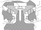
도 1 에는 차량(미도시) 내의 파워 트레인을 지지하기 위한 장치(10)가 도시되어 있다. 제1 부분은 파워 트레인에 고정되고, 제2 부분(2)은 차량, 예를 들어 차량의 몸체 요소나 섀시에 고정된다. 상기 제1 부분(1)과 제2 부분(2)은 금속, 또는 높은 기계적 강도를 가진 복합 재료로 이루어진다.1 shows an
제2 부분(2)은, 한편으로는, 적어도 하나의 진동 댐핑 버퍼(4)를 이용하여 제1 부분(1)에 고정된다.The second part 2 is, on the one hand, fixed to the first part 1 using at least one
도 1 에 도시된 실시예에서, 제2 부분(2)은 원추형 관통-개구(through-opening)를 포함하고, 상기 관통-개구 안에는 화살표 머리 모양 구조물(arrow-head-like arrangement; 14)이 수용되는데, 상기 구조물(14)은 상보적인 중실의 원추형 형상을 갖는 버퍼(4)를 포함한다.In the embodiment shown in Figure 1, the second part 2 comprises a conical through-opening in which an arrow-head-
이 예에서는, 아래의 설명에서도 마찬가지로, "원추형" 및 "원통형"이라는 용어는 그들의 가장 넓은 의미를 갖는 것으로 의도된 것이다. 원추 형상 또는 원통 형상의 베이스(base)는 반드시 원형에만 국한되는 것은 아니며, 임의의 폐쇄된 라인으로 이루어진 형상을 가질 수 있는바, 그 형상에 관한 비제한적인 예를 들자면 타원형, 오벌형(oval), 또는 다각형을 들 수 있다. 동일한 방식으로, "원추 형상"이라는 용어는 완전한 원추 형상은 물론, 절두된 형태의 원추 형상(truncated cone)도 포괄한다.In this example, the terms "conical" and "cylindrical" are likewise intended to have their broadest meaning in the description below. The base of a cone or cylinder is not necessarily limited to a circle, but may have a shape consisting of any closed lines, such as, but not limited to, elliptical, oval, , Or a polygon. In the same way, the term "conical shape" encompasses a truncated cone as well as a complete conical shape.
스크류(7)는, 한편으로 상기 구조물(14)의 상측면에 대해 가압하고, 다른 한편으로는 제1 부분(1)을 버퍼(buffer; 4)에 대해 유지시키기 위하여 제1 부분(1) 안으로 도입된다. 상기 버퍼(4)는 버퍼의 볼록한 원추형 벽이 제2 부분(2)의 상보적으로 오목한 원추형 벽에 대해 지탱됨으로써 자체적으로 유지된다.The
연속 매체(continuous media)의 기술분야에서 알려진 바와 같이, 댐핑 버퍼(4)는 기계적 관점에서 선형적 복원성(linear resilience)을 갖는 유연성 재료로 만들어지는바, 예를 들어 제1 강성 계수(K4)를 갖는 엘라스토머 재료로 만들어진다.As is known in the art of continuous media, the
댐핑의 기술분야에서 알려진 바와 같이, 버퍼(4)를 위하여는 강성 계수(K4)를 갖는 유연성 재료가 선택되는바, 후크의 법칙(Hooke's laws)에 근거한 통상의 관점에서 강성 계수(K4)는 제1 부분(1)과 제2 부분(2)이 서로에 대해 맞닿음을 방지하기에는 충분하되 제1 부분이 제2 부분에 대해 변위함을 허용하도록 충분히 작다. 이와 같은 선택에 따르면 보통의 작동 조건 하에서의 충분한 팽창/압축에 의하여 버퍼(4)가 에너지(E4)를 흡수할 수 있게 된다. 이와 같은 방식으로, 버퍼(4)는 보통 작동 중에 파워 트레인(GMP)의 진동을 필터링(filtering)한다.As is known in the art of damping,
제1 부분의 수직 벽(8)을 둘러싸는 제2 부분(2)의 내부 수직 벽에는 하나 이상의 변위 제한 장치(6)(들)이 고정된다. 도시된 실시예에서는, 수 개의 변위 제한 장치(6)들이 버섯 형태를 가지고 있으며 또한 제2 부분(2)의 내부 수직 벽의 주변부에 걸쳐 분포되어 있다. 링의 형태를 갖는 단일의 변위 제한 장치(6)도 고찰해 볼 수 있는바, 이 경우에는 도 1 에 그 단면이 도시되어야 할 것이다.One or more displacement limiting devices (6) (s) are fixed to the inner vertical wall of the second part (2) surrounding the vertical wall (8) of the first part. In the illustrated embodiment, several
제2 부분(2)의 하측 수평 벽에는 하나 이상의 변위 제한 장치(3)(들)이 고정되어 있는바, 이것은 제1 부분의 수평 벽(9) 위에서 돌출되어 있다. 도시된 실시예에서는, 수 개의 변위 제한 장치(3)들이 버섯 형태를 가지고 있으며 또한 제2 부분(2)의 하측 수평 벽 아래에 분포되어 있다. 링의 형태를 갖는 단일의 변위 제한 장치(3)도 고찰해 볼 수 있는바, 이 경우에는 도 1 에 그 단면이 도시되어야 할 것이다.One or more displacement limiting devices 3 (s) are fixed on the lower horizontal wall of the second part 2, which protrudes above the horizontal wall 9 of the first part. In the illustrated embodiment, several displacement limiting devices 3 have a mushroom shape and are distributed beneath the lower horizontal wall of the second part 2. A single displacement restricting device 3 having a ring shape can also be considered. In this case, the cross-section thereof should be shown in Fig.
변위 제한 장치(들)(3, 6)은 제1 강성 계수(K4)보다 높은 제2 강성 계수(K3)를 갖는다.A displacement restricting device (s) (3, 6) has a first stiffness coefficient higher than the second stiffness coefficient (K 4) (K 3).
이와 같은 방식으로, 제1 부분(1)의 팁(tip)에서 스크류(7)에 의하여 현가되어 있고 파워 트레인에 고정식으로 접합되어 있는 제1 부분(1)이 적은 양만큼 우측 또는 좌측으로 기울어지는 때에는 버퍼(4)만이 작용한다.In this way, the first portion 1 suspended by the
제1 부분(1)이 우측으로 더 많이 기울어지는 때에는, 수직 벽(8) 및 수평 벽(9)의 우측 부분들이 각각 우측의 변위 제한 장치(6) 및 변위 제한 장치(3)와 충돌한다.The right portions of the vertical wall 8 and the horizontal wall 9 collide with the
동일한 방식으로, 제1 부분(1)이 좌측으로 더 많이 기울어지는 때에는, 수직 벽(8) 및 수평 벽(9)의 좌측 부분들이 각각 좌측의 변위 제한 장치(6) 및 변위 제한 장치(3)와 충돌한다.In the same way, when the first part 1 is inclined more to the left, the left portions of the vertical wall 8 and the horizontal wall 9 are connected to the
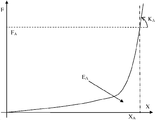
도 2 에는 도 1 의 지지 장치(10)의 거동이 그래프로서 도시되어 있다.Figure 2 shows the behavior of the
가로축 상의 X의 값은 제1 부분(1)의 변위를 나타내는바, 예를 들어 양의 방향으로는 우측을 향한 변위를 나타내고, 대칭적으로는 음의 방향으로 좌측을 향한 변위를 나타낸다.The value of X on the abscissa indicates the displacement of the first part 1, for example, a displacement toward the right in the positive direction and a displacement toward the left in the negative direction symmetrically.
세로축 상의 F의 값은 파워 트레인에 의하여 제1 부분에 가해지는 힘을 나타내는바, 이 힘은 반작용 토크(counter-reaction torque)와, 파워 트레인에 의해서 지지 장치(10)의 제1 부분(1)으로 전달되는 진동을 합친 것이다.The value of F on the vertical axis indicates the force exerted on the first part by the powertrain which is transmitted to the first part 1 of the
낮은 기울기를 갖는 선의 부분은 버퍼(4)의 작용에 해당되는바, 상기 버퍼(4)의 제1 강성 계수(K4)가 힘(F)과 변위(X) 간의 비례 관계를 결정한다.The portion of the line with a low slope corresponds to the action of the
상대적으로 높은 기울기를 갖는 선의 부분은 버퍼(4)의 작용에 변위 제한 장치들(3, 6)의 작용이 더해진 것에 해당된다. 힘(F)과 변위(X) 간의 상측 비례 관계(upper proportionality relationship)를 결정하는 제2 강성 계수(K3)는 상기 제1 강성 계수(K4)에 더해진다.The portion of the line having a relatively high slope corresponds to the action of the
알려진 바와 같이, 선 아래의 면적은 장치(10)에 의해 흡수된 에너지(E)를 변위(X)의 함수로서 나타낸다.As is known, the area under the line represents the energy (E) absorbed by the
변위(X)가 정지값(stop value; XA)에 도달하도록 힘(F)이 값(FA)에 도달하는 때에, 흡수된 에너지는 장치(10)에 의해서 흡수될 수 있는 에너지의 최대값(EA)에 도달하고, 그 이후로는 포화상태에 있게 된다. 이 상태를 넘어서면, 에너지는 제1 부분(1)으로부터 차량의 몸체에 고정식으로 결합되어 있는 제2 부분(2)으로 최대 강성 계수(KA)로 전적으로 전달된다. 결과적으로, 장치(10)를 포화 상태에 이르게하는 우연한 충격의 힘은 직접 상기 몸체를 자극하고, 이것은 차량의 탑승객 공간에서 느껴지는 진동과 소음을 발생시킨다.When the force F reaches a value F A such that the displacement X reaches a stop value X A , the absorbed energy is the maximum value of the energy that can be absorbed by the device 10 (E A ), and thereafter becomes saturated. Beyond this state, the energy is entirely transferred to the maximum stiffness coefficient K A from the first portion 1 to the second portion 2 fixedly coupled to the body of the vehicle. As a result, the force of accidental impact that causes the
도 3 에 도시된 장치(20)는 변위 제한 장치들(3, 6)의 제2 강성 계수(K3)보다 낮은 제2 강성 계수(K23)를 갖는 변위 제한 장치들(23, 26)을 포함한다는 점에서, 도 1 의 장치(10)와 상이하다.The
복원성 재료 요소(15)가 각각의 변위 제한 장치(23) 둘레에 배치되는바, 예를 들면 도 3 의 우측에서 단면으로 도시되고 도 3 의 좌측에서는 정면도로서 도시된 슬리브의 형태로 배치된다.
복원성 재료 요소(25)는 각각의 변위 제한 장치(26) 둘레에 배치되며, 예를 들어 도 3 의 우측에서 단면으로 도시되고 도 3 의 좌측에서는 정면도로서 도시된 슬리브의 형태로 배치된다.
상기 복원성 재료 요소들(15, 25) 각각은 제2 강성 계수(K23)보다 높은 제3 강성 계수(K5)를 갖는다.Each of the
유리하게는, 일부 특정의 실시예들에서, 복원성 재료 요소(15, 25)에 장착된 각각의 변위 제한 장치(23, 26)가 변위 제한 장치(3, 6)보다 더 길다.Advantageously, in some particular embodiments, each of the
제1 부분(1)이 지지 장치(20)의 제2 부분(2)에 가까이 가면, 제1 부분은 제1 부분이 접근하는 변위 제한 장치(26) 및/또는 변위 제한 장치(23)에 대한 압축력을 발생시킨다.When the first part 1 approaches the second part 2 of the
상기 압축력을 받는 변위 제한 장치(23, 26)는 찌부러지는 경향을 갖는바, 즉 그 길이가 감소되고 그 직경이 증가하게 된다.The
변위 제한 장치(23, 26)의 직경 증가를 제한하도록 배치된 복원성 재료 요소(15, 25)는 더 높은 강성 계수(K5)를 갖기 때문에, 변위 제한 장치(23, 26)에 대해 반발 부하(reaction load)를 인가한다.Rebound load for the displacement limiting device (23, 26) of resilient material (15, 25) arranged to limit the increase in the diameter of the more since it has a high rigidity coefficient (K 5), the displacement limiting device (23, 26) ( reaction load.
제1 부분의 변위가 계속되면, 변위 제한 장치(23, 26)는 제1 부분이 복원성 재료 요소(15, 25)와 접촉하게 될 때까지 그 압축이 계속되고, 그 접촉이 있게 되면 복원성 재료 요소(15, 25)가 이동의 끝인 정지부로서 작용한다.If displacement of the first part continues, the
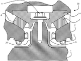
도 4 에 도시된 장치(30)는 종전의 변위 제한 장치(3, 6)를 포함하지만, 이것은 도 1 에 도시된 장치(10)의 변위 제한 장치와 반드시 동일한 것은 아니다.The
장치(30)는, 변위 제한 장치(3, 6)의 반대측인 제1 부분(1) 상에 장착된 복원성 재료 요소(35)를 포함한다는 점에서 장치(10)와 상이하다.The
복원성 재료 요소(35)는 제1 부분(1)에 장착되되 제2 부분(2)의 반대측에 있는 적어도 하나의 표면 상에 장착되며, 이로써 복원성 재료 요소(35)는 제1 부분(1)과 제2 부분(2) 사이에 배치된다.The
복원성 재료 요소(35)는 제2 강성 계수(K3)보다 낮은 제3 강성 계수(K5)를 갖는다.The
제1 부분(1)이 지지 장치(30)의 제2 부분(2)에 가까워지게 움직이면, 제1 부분은 제1 부분(1)이 접근하는 변위 제한 장치(6) 및/또는 변위 제한 장치(3)에 대한 복원성 재료 요소(35)의 압축력을 발생시킨다.When the first part 1 moves closer to the second part 2 of the
변위 제한 장치(3, 6)와 제1 부분(1) 사이에 배치된 복원성 재료 요소(35)는 낮은 강성 계수(K5)를 갖기 때문에, 변위 제한 장치(3, 6)에 의해 가해지는 반반 부하에 의해 찌부러진다.Since the restoring
반발 부하를 받는 변위 제한 장치(3, 6)도 찌부러지는 경향을 갖지만, 상대적으로 높은 강성 계수(K3)를 갖기 때문에 복원성 재료 요소(35)보다는 적게 찌부러진다.The
제1 부분의 변위가 계속되면, 복원성 재료 요소(35)는 가능한 압축의 포화 상태에 이르게 되며, 변위 제한 장치(3, 6)는 자신이 이동의 끝인 정지부로서 작용하게 될 때까지 계속하여 압축된다.If the displacement of the first part continues, then the restoring
도 5 에는 제2 강성 계수(K23)보다 높은 제3 강성 계수(K5)를 갖는 복원성 재료 요소(15, 25)를 갖는 도 3 에 도시된 지지 장치(20)와, 제2 강성 계수(K3)보다 낮은 제3 강성 계수(K5)를 갖는 복원성 재료 요소(35)를 갖는 도 4 에 도시된 지지 장치(30)의 거동이 그래프로서 도시되어 있다.Figure 5 shows a second and rigidity coefficient (K 23) higher than the third stiffness coefficient of the
도 2 의 그래프에서와 같이, 수평축의 X의 값은 제1 부분(1)의 변위를 나타내고, 수직축의 F의 값은 파워 트레인에 의하여 제1 부분에 가해지는 힘을 나타낸다.2, the value of X on the horizontal axis represents the displacement of the first part 1 and the value of F on the vertical axis represents the force applied to the first part by the powertrain.
이 경우에도, 낮은 기울기를 갖는 선의 시작 부분은 버퍼(4)의 작용에 해당되며, 상기 버퍼(4)의 제1 강성 계수(K4)만이 작은 범위의 변위(X)와 힘(F) 간의 비례 관계를 결정한다.In this case also, the beginning of the line with a low slope corresponds to the action of the
그 다음, 기울기는 제1 증가를 겪게 되는바, 상기 제1 증가는 장치(20)에서의 버퍼(4)의 작용, 변위 제한 장치(23, 26)의 작용, 및 무시가능한 값의 변위를 일으키는 높은 제3 강성 계수(K5)를 갖는 복원성 요소(15, 25)의 상대적으로 적은 크기의 작용의 합에 해당되거나, 또는 장치(30)에서의 버퍼(4)의 작용, 복원성 요소(25)의 작용, 및 무시가능한 값의 변위를 일으키는 높은 제2 강성 계수(K3)를 갖는 변위 제한 장치(3, 6)의 상대적으로 적은 크기의 작용의 합에 해당된다.The slope then undergoes a first increase, which is due to the action of the
복원성 요소들과 변위 제한 장치들의 강성 레벨(stiffness level)이 직렬로 되어 있는 구조물의 장점은, 병렬로 되어 있는 구조물과 대비하면 쉽게 이해될 것이며, 이것은 도 5 의 선으로부터 보다 명확히 이해될 것이다.The advantage of a structure in which the stiffness levels of the stability elements and the displacement limiting devices are in series will be easily understood when compared to a structure in parallel, which will be more clearly understood from the line in FIG.
낮은 강성 계수(K)를 갖는 변위 제한 장치(23, 26) 또는 복원성 요소(35)가 처음에 작용할 때에는 도 2 의 선에서 볼 수 있는 높은 기울기가 아닌 기울기로 상승한다.When the
높은 강성 계수(K)를 갖는 변위 제한 장치(3, 6) 또는 복원성 요소(15, 25)도 작용하게 될 때에는, 겪게 되는 동일한 힘(F)에 대해서 상대적으로 높은 강성 계수(K)가 적은 변위를 일으키기 때문에 반발력으로 인하여 적은 양만큼만 작용하게 된다.When the
초기에 낮은 강성 계수(K)를 갖는, 장치(30)의 복원성 요소(35) 또는 장치(20)의 변위 제한 장치(23, 26)의 압축 중에, 복원성 요소(35) 또는 변위 제한 장치(23, 26)가 각각 포화 상태에 들어서게 됨으로 인한 영향 하에서 변위 제한 장치(3, 6) 또는 복원성 요소(15, 25) 각각이 점진적으로 작용하게 된다.During the compression of the restraining
도 5 에서 도 2 에 도시된 흡수된 에너지(EA)와 동일한 에너지에 대해 검토하면, 장치(20 또는 30)가 그 에너지를 흡수할 수 있는 변위(X'A)를 겪게 되는 때에 강성 계수(K'A)는 강성 계수(KA)보다 더 낮다는 것을 알 수 있다. 또한, 이동의 끝에서의 충격력(F'A)이 장치(10)와 관련하여 도 2 에서 관찰된 힘(FA)보다 낮다는 것을 알 수 있다.Considering the same energy as the absorbed energy E A shown in Fig. 5 in Fig. 2, when the
장치들(20, 30)에 의하여 흡수되는 에너지(EA)의 분포가 장치(10)의 경우보다 더 우수하기 때문에 적어도 두 가지의 유리한 기술적 효과가 발생된다. 한편으로는, 이동 끝에서의 충격력(F'A)이 충격력(FA)보다 낮기 때문에 소음이 적게 발생한다. 다른 한편으로는, 이동 끝에서의 강성 계수(K'A)가 강성 계수(KA)보다 낮기 때문에 파워 트레인으로부터 차량의 몸체(bodywork)에 전달되는 소음이 적게 된다.At least two advantageous technical effects arise because the distribution of the energy E A absorbed by the
그러나, 본 발명에 따른 상기 장치의 구조의 장점은 이에 그치지 않으며, 위에서 설명된 구조는 현존하는 장치들에 간편하고 비용효율적인 방식으로 소음을 저감시키는 방안을 구현함을 가능하게 한다는 장점도 있다.However, the advantages of the structure of the device according to the invention are not limited, and the structure described above also has the advantage that it is possible to implement a noise reducing method in existing devices in a simple and cost-effective manner.
이제 현존하는 지지 장치(10)에 대하여 고찰하는바, 상기 지지 장치(10)는 파워 트레인에 고정되는 제1 부분(1), 한편으로는 차량에 고정되고 다른 한편으로는 제1 강성 계수(K4)를 갖는 진동 댐핑 버퍼(4)를 이용하여 제1 부분(1)에 고정되는 제2 부분(2), 및 제1 강성 계수(K4)보다 높은 제2 강성 계수(K3)를 갖는 적어도 하나의 변위 제한 장치를 포함한다.Consider now the existing
지지 장치(10)가 불쾌한 소음을 발생시키는 때에는 소음 저감 방법이 구현되는바, 그 방법은 지지 장치(20 또는 30)가 구현되도록 하나 이상의 추가적인 복원성 재료 요소를 특정의 방식으로 지지 장치(10)에 배치시키는 단계를 포함한다.A noise reduction method is implemented when the
상기 지지 장치(20)를 구현하는 단계는 간편하게도, 예를 들어 슬리브 형태를 갖는 복원성 재료 요소(15, 25)를 변위 제한 장치 둘레에 배치시킴을 포함한다.The step of embodying the
대안적으로, 상기 지지 장치(30)를 구현하는 단계는 간편하게도, 상기 제2 부분(2)의 반대쪽에 있는 제1 부분(1) 상의 적어도 일 표면에 슬리브 형태를 갖는 복원성 재료 요소(35)를 장착시켜 배치시킴을 포함한다.Alternatively, the step of embodying the
이와 같은 방식으로 배치된 상태에서, 제2 부분으로 가까워지게 움직이는 제1 부분이 변위 제한 장치에 대한 압축력을 발생시키는 때에는, 복원성 재료 요소가 변위 제한 장치에 대해 반발 부하를 인가하게 된다.In a state in which it is arranged in this way, when the first part moving closer to the second part generates a compressive force for the displacement limiting device, the restoring material element applies a repulsive load to the displacement limiting device.
본 발명에 따른 방법을 이용하여 이와 같은 방식으로 용이하게 구현되는 변위 제한 장치에 대한 반발 부하는, 버퍼(4)와 변위 제한 장치들(3, 6, 23, 26) 사이에서 흡수되는 에너지가 보다 점진적으로 그리고 보다 완전한 방식으로 분포됨을 가능하게 하는바, 이로써 충격력(F'A)에 의해 발생되는 첫 번째 소음이 감소되며, 제1 부분이 맞닿음 위치로 움직인 경우에 있어서의 결과적인 강성 계수(K'A)에 의해서 제1 부분(1)으로부터 제2 부분으로 전달되는 두 번째 소음도 상기 충격력의 감소와 상기 결과적인 강성 계수로 인하여 감소된다.The repulsive load on the displacement limiting device, which is easily implemented in this way using the method according to the invention, is such that the energy absorbed between the
Claims (12)
상기 제2 부분에 가까워지게 움직이는 제1 부분이 상기 변위 제한 장치에 대한 압축력(compression force)을 발생시키는 때에 상기 변위 제한 장치(3, 23, 6, 26)에 대해 반발 부하(reaction load)를 인가하도록 배치된 적어도 하나의 복원성 재료 요소(element of resilient material; 15, 25, 35)를 포함하는 것을 특징으로 하는, 차량 내의 파워 트레인용 지지 장치(20, 30).At least one vibration damping buffer (4) having a first portion (1) fixed to the power train, a vibration damping buffer (4) fixed to the vehicle and, on the other hand, a first stiffness coefficient, A second portion 2 fixed to the first portion 1 with a first stiffness coefficient and at least one displacement limiting device 3, 23 having a second stiffness coefficient higher than the first stiffness coefficient , 6, 26) for supporting a power train in a vehicle,
A reaction load is applied to the displacement limiting device (3, 23, 6, 26) when a first portion moving toward the second portion generates a compression force for the displacement limiting device Characterized in that it comprises at least one element of resilient material (15, 25, 35) arranged so as to be able to support the power train (20, 30).
상기 복원성 재료 요소(15, 25, 35)는 슬리브(sleeve) 형태를 갖는 것을 특징으로 하는, 차량 내의 파워 트레인용 지지 장치(20, 30).The method according to claim 1,
Characterized in that the resilient material elements (15, 25, 35) are in the form of a sleeve.
적어도 하나의 변위 제한 장치(3, 23, 6, 26)는 제2 부분(2)에 고정된 것을 특징으로 하는, 차량 내의 파워 트레인용 지지 장치(20, 30).3. The method according to claim 1 or 2,
Characterized in that at least one displacement limiting device (3, 23, 6, 26) is fixed to the second part (2).
상기 복원성 재료 요소(15, 25)는 상기 변위 제한 장치(23, 26) 둘레에 배치된 것을 특징으로 하는, 차량 내의 파워 트레인용 지지 장치(20).4. The method according to any one of claims 1 to 3,
Characterized in that the restoring material elements (15, 25) are arranged around the displacement limiting devices (23, 26).
상기 복원성 재료 요소(15, 25)는 제2 강성 계수보다 높은 제3 강성 계수를 갖는 것을 특징으로 하는, 차량 내의 파워 트레인용 지지 장치(20).5. The method of claim 4,
Characterized in that the resilient material elements (15, 25) have a third stiffness coefficient higher than the second stiffness coefficient.
상기 복원성 재료 요소(35)는 변위 제한 장치(3, 6) 반대측의 제1 부분(1) 상에 장착된 것을 특징으로 하는, 차량 내의 파워 트레인용 지지 장치(30).4. The method according to any one of claims 1 to 3,
Characterized in that the resilient material element (35) is mounted on a first part (1) opposite the displacement limiting device (3, 6).
상기 복원성 재료 요소(35)는 제1 부분(1)과 제2 부분(2) 사이에 배치된 것을 특징으로 하는, 차량 내의 파워 트레인용 지지 장치(30).4. The method according to any one of claims 1 to 3,
Characterized in that the resilient material element (35) is arranged between the first part (1) and the second part (2).
상기 복원성 재료 요소(35)는 제1 부분(1)에 장착되되 제2 부분(2)의 반대측에 있는 적어도 일 표면 상에 장착되는 것을 특징으로 하는, 차량 내의 파워 트레인용 지지 장치(30).8. The method according to claim 6 or 7,
Characterized in that the resilient material element (35) is mounted on at least one surface mounted on the first part (1) and on the opposite side of the second part (2).
상기 복원성 재료 요소(35)는 제2 강성 계수보다 낮은 제3 강성 계수를 갖는 것을 특징으로 하는, 차량 내의 파워 트레인용 지지 장치(30).9. The method according to any one of claims 6 to 8,
Characterized in that the resilient material element (35) has a third stiffness coefficient lower than the second stiffness coefficient.
상기 제2 부분에 가까워지게 움직이는 제1 부분이 변위 제한 장치에 대해 압축력을 일으키는 때에 상기 변위 제한 장치(3, 23, 6, 26)에 대해 반발 부하를 인가하기 위하여 적어도 하나의 복원성 재료 요소(15, 25, 35)를 상기 지지 장치(10)에 배치시키는 단계를 포함하는 것을 특징으로 하는, 차량 내의 파워 트레인용 지지 장치의 소음 저감 방법.A method of reducing noise in a support device (10) when the powertrain in the vehicle is over displaced, the support device (10) comprising a first part (1) fixed to the powertrain, On the one hand, a second part (2) fixed to the first part (1) using at least one vibration damping buffer (4) having a first stiffness coefficient, and a second stiffness coefficient At least one displacement limiting device (3, 23, 6, 26)
Wherein at least one resilient material element (15) is provided for applying a repulsive load to the displacement limiting device (3, 23, 6, 26) when the first part moving towards the second part causes a compressive force on the displacement restricting device , 25, 35) to the support device (10). The method of claim 1, further comprising:
상기 복원성 재료 요소(15, 25)는 상기 변위 제한 장치(23, 26) 둘레에 배치된 것을 특징으로 하는, 차량 내의 파워 트레인용 지지 장치의 소음 저감 방법.11. The method of claim 10,
Characterized in that the restoring material elements (15, 25) are arranged around the displacement limiting devices (23, 26).
상기 복원성 재료 요소(35)는 상기 제2 부분(2)에 장착되되 상기 제1 부분(1)의 반대측에 있는 적어도 일 표면 위에 장착됨으로써 배치되는 것을 특징으로 하는, 차량 내의 파워 트레인용 지지 장치의 소음 저감 방법.11. The method of claim 10,
Characterized in that the resilient material element (35) is arranged to be mounted on at least one surface of the second part (2) which is opposite to the first part (1) Noise reduction method.
Applications Claiming Priority (3)
| Application Number | Priority Date | Filing Date | Title |
|---|---|---|---|
| FR1159518 | 2011-10-20 | ||
| FR1159518A FR2981610B1 (en) | 2011-10-20 | 2011-10-20 | MOTOR PUSH GROUP SUPPORT DEVICE IN A VEHICLE |
| PCT/FR2012/052257 WO2013057408A1 (en) | 2011-10-20 | 2012-10-05 | Support device for a power train in a vehicle |
Publications (2)
| Publication Number | Publication Date |
|---|---|
| KR20140077954A true KR20140077954A (en) | 2014-06-24 |
| KR101970462B1 KR101970462B1 (en) | 2019-04-19 |
Family
ID=47071402
Family Applications (1)
| Application Number | Title | Priority Date | Filing Date |
|---|---|---|---|
| KR1020147012428A Active KR101970462B1 (en) | 2011-10-20 | 2012-10-05 | Support device for a power train in a vehicle |
Country Status (4)
| Country | Link |
|---|---|
| KR (1) | KR101970462B1 (en) |
| CN (1) | CN103930290B (en) |
| FR (1) | FR2981610B1 (en) |
| WO (1) | WO2013057408A1 (en) |
Cited By (1)
| Publication number | Priority date | Publication date | Assignee | Title |
|---|---|---|---|---|
| CN110435407A (en) * | 2018-05-04 | 2019-11-12 | 通用汽车环球科技运作有限责任公司 | Base assembly for vehicle |
Families Citing this family (4)
| Publication number | Priority date | Publication date | Assignee | Title |
|---|---|---|---|---|
| JP6355255B2 (en) | 2014-10-03 | 2018-07-11 | 株式会社ブリヂストン | Vibration isolator |
| FR3043365B1 (en) * | 2015-11-10 | 2017-11-03 | Renault Sas | DEVICE FOR FASTENING A POWER PLANT |
| US11236791B2 (en) * | 2019-10-18 | 2022-02-01 | Raytheon Company | Multi-axial energy damping and displacement control |
| CN115750665A (en) * | 2022-11-16 | 2023-03-07 | 北京航天发射技术研究所 | Support damping device |
Citations (6)
| Publication number | Priority date | Publication date | Assignee | Title |
|---|---|---|---|---|
| FR2363033A1 (en) * | 1976-08-23 | 1978-03-24 | Metzeler Kautschuk | Motor mounting with elastomeric block between rigid members - has adjustable stops to limit relative vibrational movement of members |
| US4151822A (en) * | 1976-05-06 | 1979-05-01 | Honda Giken Kogyo Kabushiki Kaisha | Apparatus for supporting an internal combustion engine |
| JPH0293134A (en) * | 1988-09-29 | 1990-04-03 | Kinugawa Rubber Ind Co Ltd | Vibration isolating bush |
| DE10260520A1 (en) * | 2002-12-21 | 2004-07-01 | Volkswagen Ag | Automobile wheel steering arm with elastomer bearing having stop for limiting relative movement transverse to radial freedom of movement |
| WO2005018904A1 (en) * | 2003-08-25 | 2005-03-03 | Toyo Tire & Rubber Co., Ltd. | Method of manufacturing vibration control device |
| EP1953408A1 (en) * | 2007-02-05 | 2008-08-06 | Egidio Di Sora | A device for supporting, limiting, and providing a stop for a moving item or unit equipped with an elastic element of a dual-compound type, and a process for obtaining said elastic element |
Family Cites Families (1)
| Publication number | Priority date | Publication date | Assignee | Title |
|---|---|---|---|---|
| FR2895322B1 (en) * | 2005-12-22 | 2008-04-04 | Renault Sas | MOTOR VEHICLE COMPRISING A REVERSE POWER UNIT THAT CAN TILT DURING AN IMPACT |
-
2011
- 2011-10-20 FR FR1159518A patent/FR2981610B1/en active Active
-
2012
- 2012-10-05 CN CN201280055435.5A patent/CN103930290B/en active Active
- 2012-10-05 KR KR1020147012428A patent/KR101970462B1/en active Active
- 2012-10-05 WO PCT/FR2012/052257 patent/WO2013057408A1/en not_active Ceased
Patent Citations (6)
| Publication number | Priority date | Publication date | Assignee | Title |
|---|---|---|---|---|
| US4151822A (en) * | 1976-05-06 | 1979-05-01 | Honda Giken Kogyo Kabushiki Kaisha | Apparatus for supporting an internal combustion engine |
| FR2363033A1 (en) * | 1976-08-23 | 1978-03-24 | Metzeler Kautschuk | Motor mounting with elastomeric block between rigid members - has adjustable stops to limit relative vibrational movement of members |
| JPH0293134A (en) * | 1988-09-29 | 1990-04-03 | Kinugawa Rubber Ind Co Ltd | Vibration isolating bush |
| DE10260520A1 (en) * | 2002-12-21 | 2004-07-01 | Volkswagen Ag | Automobile wheel steering arm with elastomer bearing having stop for limiting relative movement transverse to radial freedom of movement |
| WO2005018904A1 (en) * | 2003-08-25 | 2005-03-03 | Toyo Tire & Rubber Co., Ltd. | Method of manufacturing vibration control device |
| EP1953408A1 (en) * | 2007-02-05 | 2008-08-06 | Egidio Di Sora | A device for supporting, limiting, and providing a stop for a moving item or unit equipped with an elastic element of a dual-compound type, and a process for obtaining said elastic element |
Cited By (2)
| Publication number | Priority date | Publication date | Assignee | Title |
|---|---|---|---|---|
| CN110435407A (en) * | 2018-05-04 | 2019-11-12 | 通用汽车环球科技运作有限责任公司 | Base assembly for vehicle |
| CN110435407B (en) * | 2018-05-04 | 2022-06-07 | 通用汽车环球科技运作有限责任公司 | Base assembly for vehicle |
Also Published As
| Publication number | Publication date |
|---|---|
| WO2013057408A1 (en) | 2013-04-25 |
| CN103930290B (en) | 2018-01-02 |
| FR2981610B1 (en) | 2014-08-29 |
| FR2981610A1 (en) | 2013-04-26 |
| CN103930290A (en) | 2014-07-16 |
| KR101970462B1 (en) | 2019-04-19 |
Similar Documents
| Publication | Publication Date | Title |
|---|---|---|
| KR101970462B1 (en) | Support device for a power train in a vehicle | |
| JP5793186B2 (en) | Preloaded double spring assembly | |
| JP5864980B2 (en) | Rebound stopper for strut assembly for vehicle suspension system | |
| JP2010506101A (en) | Air spring especially for vehicle suspension | |
| CN105564166A (en) | Tow hook structure and automobile | |
| CN107627802A (en) | For vehicle suspension system buffer unit and there is its vehicle | |
| CN101366158B (en) | End clamps for trailed lines | |
| CN104924870A (en) | Mobile robot suspension damper with double combined spiral springs | |
| CN103363016A (en) | Dumper power assembly vibration isolator for mine | |
| JP2006518296A (en) | Vibration absorption mechanism for wheels running on tires filled with air | |
| JP3725346B2 (en) | Anti-vibration mount | |
| KR20120020753A (en) | Roll rod for vehicle | |
| CN218894909U (en) | Shock absorber mechanism for improving tire ground grabbing performance | |
| CN102514473B (en) | Left suspension bracket of automobile engine | |
| JP5823447B2 (en) | Double shock absorber | |
| CN204755722U (en) | Automobile engine damping device assembly | |
| CN104121316B (en) | A kind of damper | |
| JP2001193777A (en) | Damper for vehicle | |
| KR102109426B1 (en) | Strut assambly | |
| RU2627172C1 (en) | Kochetov method for vibration isolation damping variable structure | |
| JP2007127173A (en) | Bound stopper | |
| CN216102600U (en) | Shock-absorbing frame structure | |
| KR20020044700A (en) | Shock-absorber having a bump-stopper | |
| KR19980052693U (en) | Suspension | |
| JP2009214732A (en) | Suspension device for vehicle |
Legal Events
| Date | Code | Title | Description |
|---|---|---|---|
| PA0105 | International application |
St.27 status event code: A-0-1-A10-A15-nap-PA0105 |
|
| PG1501 | Laying open of application |
St.27 status event code: A-1-1-Q10-Q12-nap-PG1501 |
|
| A201 | Request for examination | ||
| PA0201 | Request for examination |
St.27 status event code: A-1-2-D10-D11-exm-PA0201 |
|
| E902 | Notification of reason for refusal | ||
| PE0902 | Notice of grounds for rejection |
St.27 status event code: A-1-2-D10-D21-exm-PE0902 |
|
| P11-X000 | Amendment of application requested |
St.27 status event code: A-2-2-P10-P11-nap-X000 |
|
| P13-X000 | Application amended |
St.27 status event code: A-2-2-P10-P13-nap-X000 |
|
| E701 | Decision to grant or registration of patent right | ||
| PE0701 | Decision of registration |
St.27 status event code: A-1-2-D10-D22-exm-PE0701 |
|
| GRNT | Written decision to grant | ||
| PR0701 | Registration of establishment |
St.27 status event code: A-2-4-F10-F11-exm-PR0701 |
|
| PR1002 | Payment of registration fee |
St.27 status event code: A-2-2-U10-U12-oth-PR1002 Fee payment year number: 1 |
|
| PG1601 | Publication of registration |
St.27 status event code: A-4-4-Q10-Q13-nap-PG1601 |
|
| FPAY | Annual fee payment |
Payment date: 20220407 Year of fee payment: 4 |
|
| PR1001 | Payment of annual fee |
St.27 status event code: A-4-4-U10-U11-oth-PR1001 Fee payment year number: 4 |
|
| R18-X000 | Changes to party contact information recorded |
St.27 status event code: A-5-5-R10-R18-oth-X000 |
|
| PR1001 | Payment of annual fee |
St.27 status event code: A-4-4-U10-U11-oth-PR1001 Fee payment year number: 5 |
|
| PR1001 | Payment of annual fee |
St.27 status event code: A-4-4-U10-U11-oth-PR1001 Fee payment year number: 6 |
|
| PR1001 | Payment of annual fee |
St.27 status event code: A-4-4-U10-U11-oth-PR1001 Fee payment year number: 7 |
|
| PR1001 | Payment of annual fee |
St.27 status event code: A-4-4-U10-U11-oth-PR1001 Fee payment year number: 8 |
|
| U11 | Full renewal or maintenance fee paid |
Free format text: ST27 STATUS EVENT CODE: A-4-4-U10-U11-OTH-PR1001 (AS PROVIDED BY THE NATIONAL OFFICE) Year of fee payment: 8 |