KR20140079833A - 전동기 또는 발전기 - Google Patents
전동기 또는 발전기 Download PDFInfo
- Publication number
- KR20140079833A KR20140079833A KR1020147013065A KR20147013065A KR20140079833A KR 20140079833 A KR20140079833 A KR 20140079833A KR 1020147013065 A KR1020147013065 A KR 1020147013065A KR 20147013065 A KR20147013065 A KR 20147013065A KR 20140079833 A KR20140079833 A KR 20140079833A
- Authority
- KR
- South Korea
- Prior art keywords
- rotor
- sensor
- stator
- angle
- phase
- Prior art date
- Legal status (The legal status is an assumption and is not a legal conclusion. Google has not performed a legal analysis and makes no representation as to the accuracy of the status listed.)
- Granted
Links
Images





Classifications
-
- H—ELECTRICITY
- H02—GENERATION; CONVERSION OR DISTRIBUTION OF ELECTRIC POWER
- H02K—DYNAMO-ELECTRIC MACHINES
- H02K11/00—Structural association of dynamo-electric machines with electric components or with devices for shielding, monitoring or protection
- H02K11/20—Structural association of dynamo-electric machines with electric components or with devices for shielding, monitoring or protection for measuring, monitoring, testing, protecting or switching
- H02K11/21—Devices for sensing speed or position, or actuated thereby
- H02K11/215—Magnetic effect devices, e.g. Hall-effect or magneto-resistive elements
-
- B—PERFORMING OPERATIONS; TRANSPORTING
- B60—VEHICLES IN GENERAL
- B60L—PROPULSION OF ELECTRICALLY-PROPELLED VEHICLES; SUPPLYING ELECTRIC POWER FOR AUXILIARY EQUIPMENT OF ELECTRICALLY-PROPELLED VEHICLES; ELECTRODYNAMIC BRAKE SYSTEMS FOR VEHICLES IN GENERAL; MAGNETIC SUSPENSION OR LEVITATION FOR VEHICLES; MONITORING OPERATING VARIABLES OF ELECTRICALLY-PROPELLED VEHICLES; ELECTRIC SAFETY DEVICES FOR ELECTRICALLY-PROPELLED VEHICLES
- B60L15/00—Methods, circuits, or devices for controlling the traction-motor speed of electrically-propelled vehicles
- B60L15/02—Methods, circuits, or devices for controlling the traction-motor speed of electrically-propelled vehicles characterised by the form of the current used in the control circuit
- B60L15/025—Methods, circuits, or devices for controlling the traction-motor speed of electrically-propelled vehicles characterised by the form of the current used in the control circuit using field orientation; Vector control; Direct Torque Control [DTC]
-
- B—PERFORMING OPERATIONS; TRANSPORTING
- B60—VEHICLES IN GENERAL
- B60L—PROPULSION OF ELECTRICALLY-PROPELLED VEHICLES; SUPPLYING ELECTRIC POWER FOR AUXILIARY EQUIPMENT OF ELECTRICALLY-PROPELLED VEHICLES; ELECTRODYNAMIC BRAKE SYSTEMS FOR VEHICLES IN GENERAL; MAGNETIC SUSPENSION OR LEVITATION FOR VEHICLES; MONITORING OPERATING VARIABLES OF ELECTRICALLY-PROPELLED VEHICLES; ELECTRIC SAFETY DEVICES FOR ELECTRICALLY-PROPELLED VEHICLES
- B60L15/00—Methods, circuits, or devices for controlling the traction-motor speed of electrically-propelled vehicles
- B60L15/20—Methods, circuits, or devices for controlling the traction-motor speed of electrically-propelled vehicles for control of the vehicle or its driving motor to achieve a desired performance, e.g. speed, torque, programmed variation of speed
- B60L15/2045—Methods, circuits, or devices for controlling the traction-motor speed of electrically-propelled vehicles for control of the vehicle or its driving motor to achieve a desired performance, e.g. speed, torque, programmed variation of speed for optimising the use of energy
-
- G—PHYSICS
- G01—MEASURING; TESTING
- G01D—MEASURING NOT SPECIALLY ADAPTED FOR A SPECIFIC VARIABLE; ARRANGEMENTS FOR MEASURING TWO OR MORE VARIABLES NOT COVERED IN A SINGLE OTHER SUBCLASS; TARIFF METERING APPARATUS; MEASURING OR TESTING NOT OTHERWISE PROVIDED FOR
- G01D5/00—Mechanical means for transferring the output of a sensing member; Means for converting the output of a sensing member to another variable where the form or nature of the sensing member does not constrain the means for converting; Transducers not specially adapted for a specific variable
- G01D5/12—Mechanical means for transferring the output of a sensing member; Means for converting the output of a sensing member to another variable where the form or nature of the sensing member does not constrain the means for converting; Transducers not specially adapted for a specific variable using electric or magnetic means
- G01D5/14—Mechanical means for transferring the output of a sensing member; Means for converting the output of a sensing member to another variable where the form or nature of the sensing member does not constrain the means for converting; Transducers not specially adapted for a specific variable using electric or magnetic means influencing the magnitude of a current or voltage
- G01D5/142—Mechanical means for transferring the output of a sensing member; Means for converting the output of a sensing member to another variable where the form or nature of the sensing member does not constrain the means for converting; Transducers not specially adapted for a specific variable using electric or magnetic means influencing the magnitude of a current or voltage using Hall-effect devices
- G01D5/145—Mechanical means for transferring the output of a sensing member; Means for converting the output of a sensing member to another variable where the form or nature of the sensing member does not constrain the means for converting; Transducers not specially adapted for a specific variable using electric or magnetic means influencing the magnitude of a current or voltage using Hall-effect devices influenced by the relative movement between the Hall device and magnetic fields
-
- H—ELECTRICITY
- H02—GENERATION; CONVERSION OR DISTRIBUTION OF ELECTRIC POWER
- H02K—DYNAMO-ELECTRIC MACHINES
- H02K11/00—Structural association of dynamo-electric machines with electric components or with devices for shielding, monitoring or protection
- H02K11/30—Structural association with control circuits or drive circuits
- H02K11/33—Drive circuits, e.g. power electronics
-
- H—ELECTRICITY
- H02—GENERATION; CONVERSION OR DISTRIBUTION OF ELECTRIC POWER
- H02K—DYNAMO-ELECTRIC MACHINES
- H02K29/00—Motors or generators having non-mechanical commutating devices, e.g. discharge tubes or semiconductor devices
- H02K29/06—Motors or generators having non-mechanical commutating devices, e.g. discharge tubes or semiconductor devices with position sensing devices
- H02K29/08—Motors or generators having non-mechanical commutating devices, e.g. discharge tubes or semiconductor devices with position sensing devices using magnetic effect devices, e.g. Hall-plates, magneto-resistors
-
- H—ELECTRICITY
- H02—GENERATION; CONVERSION OR DISTRIBUTION OF ELECTRIC POWER
- H02P—CONTROL OR REGULATION OF ELECTRIC MOTORS, ELECTRIC GENERATORS OR DYNAMO-ELECTRIC CONVERTERS; CONTROLLING TRANSFORMERS, REACTORS OR CHOKE COILS
- H02P21/00—Arrangements or methods for the control of electric machines by vector control, e.g. by control of field orientation
- H02P21/06—Rotor flux based control involving the use of rotor position or rotor speed sensors
-
- H—ELECTRICITY
- H02—GENERATION; CONVERSION OR DISTRIBUTION OF ELECTRIC POWER
- H02P—CONTROL OR REGULATION OF ELECTRIC MOTORS, ELECTRIC GENERATORS OR DYNAMO-ELECTRIC CONVERTERS; CONTROLLING TRANSFORMERS, REACTORS OR CHOKE COILS
- H02P6/00—Arrangements for controlling synchronous motors or other dynamo-electric motors using electronic commutation dependent on the rotor position; Electronic commutators therefor
- H02P6/14—Electronic commutators
- H02P6/16—Circuit arrangements for detecting position
-
- H—ELECTRICITY
- H02—GENERATION; CONVERSION OR DISTRIBUTION OF ELECTRIC POWER
- H02P—CONTROL OR REGULATION OF ELECTRIC MOTORS, ELECTRIC GENERATORS OR DYNAMO-ELECTRIC CONVERTERS; CONTROLLING TRANSFORMERS, REACTORS OR CHOKE COILS
- H02P9/00—Arrangements for controlling electric generators for the purpose of obtaining a desired output
- H02P9/009—Circuit arrangements for detecting rotor position
-
- B—PERFORMING OPERATIONS; TRANSPORTING
- B60—VEHICLES IN GENERAL
- B60L—PROPULSION OF ELECTRICALLY-PROPELLED VEHICLES; SUPPLYING ELECTRIC POWER FOR AUXILIARY EQUIPMENT OF ELECTRICALLY-PROPELLED VEHICLES; ELECTRODYNAMIC BRAKE SYSTEMS FOR VEHICLES IN GENERAL; MAGNETIC SUSPENSION OR LEVITATION FOR VEHICLES; MONITORING OPERATING VARIABLES OF ELECTRICALLY-PROPELLED VEHICLES; ELECTRIC SAFETY DEVICES FOR ELECTRICALLY-PROPELLED VEHICLES
- B60L2220/00—Electrical machine types; Structures or applications thereof
- B60L2220/10—Electrical machine types
- B60L2220/14—Synchronous machines
-
- B—PERFORMING OPERATIONS; TRANSPORTING
- B60—VEHICLES IN GENERAL
- B60L—PROPULSION OF ELECTRICALLY-PROPELLED VEHICLES; SUPPLYING ELECTRIC POWER FOR AUXILIARY EQUIPMENT OF ELECTRICALLY-PROPELLED VEHICLES; ELECTRODYNAMIC BRAKE SYSTEMS FOR VEHICLES IN GENERAL; MAGNETIC SUSPENSION OR LEVITATION FOR VEHICLES; MONITORING OPERATING VARIABLES OF ELECTRICALLY-PROPELLED VEHICLES; ELECTRIC SAFETY DEVICES FOR ELECTRICALLY-PROPELLED VEHICLES
- B60L2220/00—Electrical machine types; Structures or applications thereof
- B60L2220/40—Electrical machine applications
- B60L2220/44—Wheel Hub motors, i.e. integrated in the wheel hub
-
- B—PERFORMING OPERATIONS; TRANSPORTING
- B60—VEHICLES IN GENERAL
- B60L—PROPULSION OF ELECTRICALLY-PROPELLED VEHICLES; SUPPLYING ELECTRIC POWER FOR AUXILIARY EQUIPMENT OF ELECTRICALLY-PROPELLED VEHICLES; ELECTRODYNAMIC BRAKE SYSTEMS FOR VEHICLES IN GENERAL; MAGNETIC SUSPENSION OR LEVITATION FOR VEHICLES; MONITORING OPERATING VARIABLES OF ELECTRICALLY-PROPELLED VEHICLES; ELECTRIC SAFETY DEVICES FOR ELECTRICALLY-PROPELLED VEHICLES
- B60L2240/00—Control parameters of input or output; Target parameters
- B60L2240/40—Drive Train control parameters
- B60L2240/42—Drive Train control parameters related to electric machines
- B60L2240/421—Speed
-
- B—PERFORMING OPERATIONS; TRANSPORTING
- B60—VEHICLES IN GENERAL
- B60L—PROPULSION OF ELECTRICALLY-PROPELLED VEHICLES; SUPPLYING ELECTRIC POWER FOR AUXILIARY EQUIPMENT OF ELECTRICALLY-PROPELLED VEHICLES; ELECTRODYNAMIC BRAKE SYSTEMS FOR VEHICLES IN GENERAL; MAGNETIC SUSPENSION OR LEVITATION FOR VEHICLES; MONITORING OPERATING VARIABLES OF ELECTRICALLY-PROPELLED VEHICLES; ELECTRIC SAFETY DEVICES FOR ELECTRICALLY-PROPELLED VEHICLES
- B60L2270/00—Problem solutions or means not otherwise provided for
- B60L2270/10—Emission reduction
- B60L2270/14—Emission reduction of noise
- B60L2270/142—Emission reduction of noise acoustic
-
- B—PERFORMING OPERATIONS; TRANSPORTING
- B60—VEHICLES IN GENERAL
- B60L—PROPULSION OF ELECTRICALLY-PROPELLED VEHICLES; SUPPLYING ELECTRIC POWER FOR AUXILIARY EQUIPMENT OF ELECTRICALLY-PROPELLED VEHICLES; ELECTRODYNAMIC BRAKE SYSTEMS FOR VEHICLES IN GENERAL; MAGNETIC SUSPENSION OR LEVITATION FOR VEHICLES; MONITORING OPERATING VARIABLES OF ELECTRICALLY-PROPELLED VEHICLES; ELECTRIC SAFETY DEVICES FOR ELECTRICALLY-PROPELLED VEHICLES
- B60L2270/00—Problem solutions or means not otherwise provided for
- B60L2270/10—Emission reduction
- B60L2270/14—Emission reduction of noise
- B60L2270/145—Structure borne vibrations
-
- H—ELECTRICITY
- H02—GENERATION; CONVERSION OR DISTRIBUTION OF ELECTRIC POWER
- H02K—DYNAMO-ELECTRIC MACHINES
- H02K2213/00—Specific aspects, not otherwise provided for and not covered by codes H02K2201/00 - H02K2211/00
- H02K2213/12—Machines characterised by the modularity of some components
-
- H—ELECTRICITY
- H02—GENERATION; CONVERSION OR DISTRIBUTION OF ELECTRIC POWER
- H02K—DYNAMO-ELECTRIC MACHINES
- H02K3/00—Details of windings
- H02K3/04—Windings characterised by the conductor shape, form or construction, e.g. with bar conductors
- H02K3/28—Layout of windings or of connections between windings
-
- H—ELECTRICITY
- H02—GENERATION; CONVERSION OR DISTRIBUTION OF ELECTRIC POWER
- H02K—DYNAMO-ELECTRIC MACHINES
- H02K7/00—Arrangements for handling mechanical energy structurally associated with dynamo-electric machines, e.g. structural association with mechanical driving motors or auxiliary dynamo-electric machines
- H02K7/14—Structural association with mechanical loads, e.g. with hand-held machine tools or fans
-
- Y—GENERAL TAGGING OF NEW TECHNOLOGICAL DEVELOPMENTS; GENERAL TAGGING OF CROSS-SECTIONAL TECHNOLOGIES SPANNING OVER SEVERAL SECTIONS OF THE IPC; TECHNICAL SUBJECTS COVERED BY FORMER USPC CROSS-REFERENCE ART COLLECTIONS [XRACs] AND DIGESTS
- Y02—TECHNOLOGIES OR APPLICATIONS FOR MITIGATION OR ADAPTATION AGAINST CLIMATE CHANGE
- Y02T—CLIMATE CHANGE MITIGATION TECHNOLOGIES RELATED TO TRANSPORTATION
- Y02T10/00—Road transport of goods or passengers
- Y02T10/60—Other road transportation technologies with climate change mitigation effect
- Y02T10/64—Electric machine technologies in electromobility
-
- Y—GENERAL TAGGING OF NEW TECHNOLOGICAL DEVELOPMENTS; GENERAL TAGGING OF CROSS-SECTIONAL TECHNOLOGIES SPANNING OVER SEVERAL SECTIONS OF THE IPC; TECHNICAL SUBJECTS COVERED BY FORMER USPC CROSS-REFERENCE ART COLLECTIONS [XRACs] AND DIGESTS
- Y02—TECHNOLOGIES OR APPLICATIONS FOR MITIGATION OR ADAPTATION AGAINST CLIMATE CHANGE
- Y02T—CLIMATE CHANGE MITIGATION TECHNOLOGIES RELATED TO TRANSPORTATION
- Y02T10/00—Road transport of goods or passengers
- Y02T10/60—Other road transportation technologies with climate change mitigation effect
- Y02T10/72—Electric energy management in electromobility
Landscapes
- Engineering & Computer Science (AREA)
- Power Engineering (AREA)
- Transportation (AREA)
- Mechanical Engineering (AREA)
- Microelectronics & Electronic Packaging (AREA)
- Physics & Mathematics (AREA)
- General Physics & Mathematics (AREA)
- Control Of Motors That Do Not Use Commutators (AREA)
- Brushless Motors (AREA)
Abstract
상기 제 2 센서는 상기 고정자에서 상기 제 1 센서와 대체로 정반대의 위치에 장착되며, 상기 제 1 센서는, 상기 회전자가 상기 고정자에 대해 회전하는 경우 제 1 자극 세트와 관련된 제 1 회전자 선속각을 나타내는 제 1 신호를 출력하기 위해 배열되고, 상기 제 2 센서는, 상기 회전자가 상기 고정자에 대해 회전하는 경우 제 1 자극 세트와 관련된 제 2 회전자 선속각을 나타내는 제 2 신호를 출력하기 위해 배열되는 전동기 또는 발전기 시스템.
Description
도 1은 6상 전동기 또는 발전기의 코일 권선들이 별모양으로 연결된 것을 나타낸다.
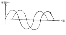
도 2는 본발명을 구현하는 전동기 내부에 장착되고 전기각 90의 차이를 가지도록 이격된 2개의 홀 센서들로부터의 출력을 나타낸다.
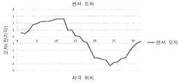
도 3은 하나의 위치 센서를 가진 전동기에 대한 위상각 오차의 오프셋의 변동을 나타낸다.
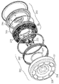
도 4는 는 본 발명을 구현하는 전동기의 분해도이다.
도 5는 도 4의 전동기를 다른 각도에서 본 분해도이다.
도 6은 본 발명을 구현하는 전동기에 장착된 정류 자석 링과 두개의 위치 센서들을 나타낸다.
도 7은 본 발명을 구현하는 전동기에 대한 코일 세트들의 배열의 일 예를 나타낸다.
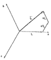
도 8은 3상 고정자의 전류의 복소 공간 벡터를 나타낸다.
도 9는 폐쇄 루프 장 지향 제어 시스템을 나타낸다.
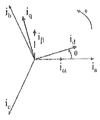
도 10은 d, q 회전 기준 프레임을 가지는 3상 고정자 전류 기준 프레임을 나타낸다.
도 11은 서로 대체로 180도의 간격을 가지는 2개의 위치 센서로 측정된 변동하는 오프셋 위상 오차에 대한 보정 데이터를 나타낸 그래프이다.
| 자석 위치 | 제 1 센서 오차 | 제 2 센서 오차 | 평균 오차 |
| 1 | -3.834228516 | 3.696899414 | -0.068664551 |
| 2 | -3.751831055 | 3.757324219 | 0.002746582 |
| 3 | -3.235473633 | 3.641967773 | 0.20324707 |
| 4 | -3.131103516 | 2.625732422 | -0.252685547 |
| 5 | -2.213745117 | 2.103881836 | -0.054931641 |
| 6 | -1.488647461 | 2.054443359 | 0.282897949 |
| 7 | -0.961303711 | 0.939331055 | -0.010986328 |
| 8 | -0.708618164 | 0.340576172 | -0.184020996 |
| 9 | 0.565795898 | 0.010986328 | 0.288391113 |
| 10 | 0.455932617 | -0.131835938 | 0.16204834 |
| 11 | 0.972290039 | -0.417480469 | 0.277404785 |
| 12 | 1.7578125 | -2.63671875 | -0.439453125 |
| 13 | 1.90612793 | -2.153320313 | -0.123596191 |
| 14 | 2.224731445 | -2.66418457 | -0.219726563 |
| 15 | 2.25769043 | -3.169555664 | -0.455932617 |
| 16 | 2.246704102 | -2.911376953 | -0.332336426 |
| 17 | 2.411499023 | -2.845458984 | -0.21697998 |
| 18 | 2.576293945 | -2.587280273 | -0.005493164 |
| 19 | 2.653198242 | -2.48840332 | 0.082397461 |
| 20 | 2.598266602 | -2.235717773 | 0.181274414 |
| 21 | 0.933837891 | -0.977783203 | -0.021972656 |
| 22 | 1.016235352 | -0.488891602 | 0.263671875 |
| 23 | 0.126342773 | 0.192260742 | 0.159301758 |
| 24 | 0.082397461 | 0.181274414 | 0.131835938 |
| 25 | -0.670166016 | 1.334838867 | 0.332336426 |
| 26 | -0.895385742 | 1.939086914 | 0.521850586 |
| 27 | -2.070922852 | 2.905883789 | 0.417480469 |
| 28 | -3.153076172 | 2.83996582 | -0.156555176 |
| 29 | -3.153076172 | 3.19152832 | 0.019226074 |
| 30 | -3.394775391 | 3.224487305 | -0.085144043 |
| 31 | -3.460693359 | 3.334350586 | -0.063171387 |
| 32 | -4.290161133 | 3.13659668 | -0.576782227 |
Claims (6)
- 제 1 자극 세트를 가지는 회전자;
제 1 센서 및 제 2 센서를 가지는 고정자; 및
상기 제 1 센서가 가리키는 제 1 회전자 선속각과 상기 제 2 센서가 가리키는 제 2 선속각의 평균에 의해 보정된 회전자 선속각을 결정하기 위해 배열된 수단;을 포함하되,
상기 제 1 센서는 상기 고정자에 장착되고,
상기 제 2 센서는 상기 고정자에서 상기 제 1 센서와 대체로 정반대의 위치에 장착되며,
상기 제 1 센서는, 상기 회전자가 상기 고정자에 대해 회전하는 경우 상기 제 1 자극 세트와 관련된 상기 제 1 회전자 선속각을 나타내는 제 1 신호를 출력하기 위해 배열되고,
상기 제 2 센서는, 상기 회전자가 상기 고정자에 대해 회전하는 경우 상기 제 1 자극 세트와 관련된 상기 제 2 회전자 선속각을 나타내는 제 2 신호를 출력하기 위해 배열되는 전동기 또는 발전기 시스템. - 제 1 항에 있어서,
상기 제 1 신호 및 상기 제 2 신호는 상기 회전자가 상기 고정자에 대하여 회전할 때 각 제 1 자석쌍 세트를 지나는 상기 제 1 센서 및 상기 제 2 센서에 대응하여 생성되는 전동기 또는 발전기. - 제 2 항에 있어서,
복수개의 코일 권선은 고정자에 장착되고 상기 회전자는 제 2 자석 세트를 포함하고,
상기 복수개의 코일 권선 및 제 2 자석 세트는 전류가 복수개의 코일 권선을 통해 흐를 때 상기 회전자에 토크가 인가되도록 배열되며,
상기 회전자에 인가되는 상기 토크는 각 권선에 흐르는 상기 전류의 위상 및 상기 제 2 자석 세트와 관련된 회전자 선속각을 기반으로 결정되는 전동기 또는 발전기. - 제 3 항에 있어서,
상기 제 1 센서 및 상기 제 2 센서가 가리키는 상기 전기 위상각의 평균은 상기 제 2 자석 세트와 관련된 상기 회전자 선속각이 상기 제 1 자극 세트에 대해 결정되도록 하는 전동기 또는 발전기. - 제 1 항 내지 제 4 항 중 어느 하나에 있어서,
상기 제 1 센서 및 상기 제 2 센서는 홀 센서인 전동기 또는 발전기. - 제 3 항의 전동기 또는 발전기가 작동하는 방법에 있어서,
각각의 상기 복수개의 코일 권선에 교류전압을 인가하는 것을 포함하고,
상기 교류 전압 위상은 상기 보정된 전기 위상각에 근거하는 전동기 또는 발전기 작동 방법.
Applications Claiming Priority (3)
| Application Number | Priority Date | Filing Date | Title |
|---|---|---|---|
| GB1118059.3A GB2483177B (en) | 2011-10-19 | 2011-10-19 | An electric motor or generator |
| GB1118059.3 | 2011-10-19 | ||
| PCT/IB2012/055309 WO2013057614A2 (en) | 2011-10-19 | 2012-10-03 | An electric motor or generator |
Publications (2)
| Publication Number | Publication Date |
|---|---|
| KR20140079833A true KR20140079833A (ko) | 2014-06-27 |
| KR101673900B1 KR101673900B1 (ko) | 2016-11-08 |
Family
ID=45219953
Family Applications (1)
| Application Number | Title | Priority Date | Filing Date |
|---|---|---|---|
| KR1020147013065A Active KR101673900B1 (ko) | 2011-10-19 | 2012-10-03 | 전동기 또는 발전기 |
Country Status (8)
| Country | Link |
|---|---|
| US (1) | US9431939B2 (ko) |
| EP (1) | EP2771204B1 (ko) |
| JP (1) | JP6030142B2 (ko) |
| KR (1) | KR101673900B1 (ko) |
| CN (1) | CN103066756B (ko) |
| GB (1) | GB2483177B (ko) |
| IN (1) | IN2014KN01023A (ko) |
| WO (1) | WO2013057614A2 (ko) |
Cited By (1)
| Publication number | Priority date | Publication date | Assignee | Title |
|---|---|---|---|---|
| KR20190039973A (ko) * | 2016-08-23 | 2019-04-16 | 프로틴 일렉트릭 리미티드 | 전기 모터용 또는 발전기용 회전자 |
Families Citing this family (18)
| Publication number | Priority date | Publication date | Assignee | Title |
|---|---|---|---|---|
| EP2829728B1 (en) * | 2013-07-22 | 2018-06-27 | Iveco France S.A.S. | Vehicle for the transportation of passengers comprising at least one axle having outer wheels including an energy recovery apparatus |
| FR3017961B1 (fr) * | 2014-02-24 | 2017-11-03 | Lohr Electromecanique | Procede de mesure du viellissement d'aimants permanents d'une machine synchrone equipee d'un capteur de position angulaire |
| FR3018014B1 (fr) | 2014-02-24 | 2016-03-25 | Lohr Electromecanique | Machine synchrone equipee d'un capteur de position angulaire |
| FR3017959B1 (fr) | 2014-02-24 | 2017-08-25 | Lohr Electromecanique | Procede de detection d'un court-circuit dans une machine synchrone equipee d'un capteur de position angulaire |
| US9613539B1 (en) * | 2014-08-19 | 2017-04-04 | Amazon Technologies, Inc. | Damage avoidance system for unmanned aerial vehicle |
| DE102015108617A1 (de) * | 2015-06-01 | 2016-12-01 | Brose Fahrzeugteile GmbH & Co. Kommanditgesellschaft, Würzburg | Bürstenloser Gleichstrommotor |
| US9705436B2 (en) * | 2015-12-04 | 2017-07-11 | Texas Instruments Incorporated | Linear hall device based field oriented control motor drive system |
| GB2552385B (en) | 2016-07-22 | 2021-09-15 | Cmr Surgical Ltd | Calibrating position sensor readings |
| EP4427953A3 (en) | 2016-09-13 | 2025-06-04 | Indigo Technologies, Inc. | Multi-bar linkage electric drive system |
| CH712932A2 (de) | 2016-09-16 | 2018-03-29 | NM Numerical Modelling GmbH | Verfahren zur Bestimmung der Position eines Positionsgebers eines Positionsmesssystems. |
| US10277084B1 (en) | 2016-10-19 | 2019-04-30 | Waymo Llc | Planar rotary transformer |
| IT201600112719A1 (it) * | 2016-11-09 | 2018-05-09 | Metalrota S R L | Un sensore magnetico per macchine elettriche rotanti. |
| TWI638512B (zh) * | 2017-09-22 | 2018-10-11 | 陳富民 | 使用預測誤差修正技術的雙電壓向量無模型式預測電流控制法則應用於內嵌式永磁同步電動機驅動系統 |
| JP6967040B2 (ja) * | 2019-07-25 | 2021-11-17 | 株式会社ソニー・インタラクティブエンタテインメント | 電気角算出装置、電気角算出方法およびプログラム |
| US12334857B2 (en) | 2020-12-04 | 2025-06-17 | Schaeffler Technologies AG & Co. KG | Method for ascertaining a rotary position, method for ascertaining an electrical angular position and method for driving an electric motor |
| US11654780B2 (en) | 2020-12-17 | 2023-05-23 | Consolidated Metco, Inc. | Vehicle electronic control unit and method |
| WO2024025848A1 (en) * | 2022-07-24 | 2024-02-01 | Navia Energy Inc. | Controlled energy system |
| FR3148977A1 (fr) * | 2023-05-22 | 2024-11-29 | Robert Bosch Automotive Steering Vendôme | Actionneur électromecanique de pilotage d’un bras rétractable de colonne de direction a fiabilité augmentée |
Citations (4)
| Publication number | Priority date | Publication date | Assignee | Title |
|---|---|---|---|---|
| JPH1052082A (ja) * | 1996-07-31 | 1998-02-20 | Victor Co Of Japan Ltd | ブラシレスモータの駆動制御回路 |
| JP2006197684A (ja) * | 2005-01-12 | 2006-07-27 | Matsushita Electric Ind Co Ltd | ブラシレスモータ |
| JP2008504799A (ja) * | 2004-06-30 | 2008-02-14 | ヴァレオ エキプマン エレクトリク モトゥール | 回転電気装置のロータの位置を決定するための装置 |
| US20080258584A1 (en) * | 2007-04-17 | 2008-10-23 | Delta Electronics, Inc. | Motor and control circuit thereof |
Family Cites Families (13)
| Publication number | Priority date | Publication date | Assignee | Title |
|---|---|---|---|---|
| DE3240580A1 (de) * | 1982-11-03 | 1984-05-03 | Ebm Elektrobau Mulfingen Gmbh & Co, 7119 Mulfingen | Kollektorloser gleichstromaussenlaeufermotor |
| JPS6218956A (ja) * | 1985-02-07 | 1987-01-27 | Sanyo Electric Co Ltd | モ−タの回転角度検出装置 |
| FR2670286B1 (fr) * | 1990-12-05 | 1993-03-26 | Moving Magnet Tech | Capteur magnetique de position et de vitesse a sonde de hall. |
| US5202610A (en) * | 1991-08-30 | 1993-04-13 | Platt Saco Lowell | Method and apparatus for yarn end-down detection in a textile yarn winding machine |
| US5148070A (en) * | 1991-08-30 | 1992-09-15 | Platt Saco Lowell Corporation | Apparatus for commutation of an electric motor |
| US5161361A (en) * | 1991-08-30 | 1992-11-10 | Platt Saco Lowell Corporation | Motor-driven spindle assembly for ring spinning |
| JPH05276783A (ja) * | 1992-03-23 | 1993-10-22 | Matsushita Electric Ind Co Ltd | モータの速度信号検出装置 |
| JP2004023800A (ja) * | 2002-06-12 | 2004-01-22 | Mitsuba Corp | ブラシレスモータ |
| DE10301271B3 (de) * | 2003-01-15 | 2004-05-13 | Siemens Ag | Elektrischer U-Boot-Antriebsmotor mit hochverfügbarer Drehwinkel- und Drehzahlerfassung |
| GB2413905B (en) * | 2004-05-05 | 2006-05-03 | Imra Europ S A S Uk Res Ct | Permanent magnet synchronous motor and controller therefor |
| TWI361555B (en) * | 2008-01-31 | 2012-04-01 | Princeton Technology Corp | Control devices and methods |
| CN101960698B (zh) * | 2008-04-07 | 2013-12-25 | 三菱电机株式会社 | 无刷电动机位置检测装置 |
| GB2472297B (en) * | 2010-07-19 | 2014-04-23 | Protean Electric Ltd | Electric motor |
-
2011
- 2011-10-19 GB GB1118059.3A patent/GB2483177B/en active Active
-
2012
- 2012-10-03 WO PCT/IB2012/055309 patent/WO2013057614A2/en not_active Ceased
- 2012-10-03 JP JP2014536358A patent/JP6030142B2/ja active Active
- 2012-10-03 EP EP12787515.1A patent/EP2771204B1/en active Active
- 2012-10-03 US US14/358,268 patent/US9431939B2/en active Active
- 2012-10-03 KR KR1020147013065A patent/KR101673900B1/ko active Active
- 2012-10-18 CN CN201210397926.XA patent/CN103066756B/zh active Active
-
2014
- 2014-05-13 IN IN1023/KOLNP/2014A patent/IN2014KN01023A/en unknown
Patent Citations (4)
| Publication number | Priority date | Publication date | Assignee | Title |
|---|---|---|---|---|
| JPH1052082A (ja) * | 1996-07-31 | 1998-02-20 | Victor Co Of Japan Ltd | ブラシレスモータの駆動制御回路 |
| JP2008504799A (ja) * | 2004-06-30 | 2008-02-14 | ヴァレオ エキプマン エレクトリク モトゥール | 回転電気装置のロータの位置を決定するための装置 |
| JP2006197684A (ja) * | 2005-01-12 | 2006-07-27 | Matsushita Electric Ind Co Ltd | ブラシレスモータ |
| US20080258584A1 (en) * | 2007-04-17 | 2008-10-23 | Delta Electronics, Inc. | Motor and control circuit thereof |
Cited By (1)
| Publication number | Priority date | Publication date | Assignee | Title |
|---|---|---|---|---|
| KR20190039973A (ko) * | 2016-08-23 | 2019-04-16 | 프로틴 일렉트릭 리미티드 | 전기 모터용 또는 발전기용 회전자 |
Also Published As
| Publication number | Publication date |
|---|---|
| US9431939B2 (en) | 2016-08-30 |
| JP6030142B2 (ja) | 2016-11-24 |
| GB2483177B (en) | 2013-10-02 |
| GB201118059D0 (en) | 2011-11-30 |
| JP2015507910A (ja) | 2015-03-12 |
| KR101673900B1 (ko) | 2016-11-08 |
| WO2013057614A3 (en) | 2015-01-08 |
| EP2771204B1 (en) | 2024-11-27 |
| CN103066756A (zh) | 2013-04-24 |
| GB2483177A (en) | 2012-02-29 |
| WO2013057614A2 (en) | 2013-04-25 |
| EP2771204A2 (en) | 2014-09-03 |
| IN2014KN01023A (en) | 2015-10-09 |
| CN103066756B (zh) | 2016-03-02 |
| US20140265970A1 (en) | 2014-09-18 |
Similar Documents
| Publication | Publication Date | Title |
|---|---|---|
| KR101673900B1 (ko) | 전동기 또는 발전기 | |
| EP3707819B1 (en) | A control device | |
| US9059659B2 (en) | Method and system for measuring a characteristic of an electric motor | |
| KR101952158B1 (ko) | 전동기 또는 발전기 | |
| US20160190972A1 (en) | Power conversion device | |
| US20130334937A1 (en) | Rotary electric machine driving system | |
| US10284121B2 (en) | Permanent magnet motor with absolute rotor position detection | |
| US9423463B2 (en) | Method and control unit for an electric motor or generator | |
| CN111034013B (zh) | 三相同步电动机的控制装置和使用其的电动助力转向装置 | |
| JP7321385B2 (ja) | 回転機の制御装置 | |
| CN114389505A (zh) | 电流检测装置以及交流旋转电机的控制装置 | |
| CN114384296A (zh) | 电流检测装置 | |
| WO2022162989A1 (ja) | 電動機の制御装置 | |
| WO2021106609A1 (ja) | 電力変換装置 |
Legal Events
| Date | Code | Title | Description |
|---|---|---|---|
| PA0105 | International application |
St.27 status event code: A-0-1-A10-A15-nap-PA0105 |
|
| A201 | Request for examination | ||
| PA0201 | Request for examination |
St.27 status event code: A-1-2-D10-D11-exm-PA0201 |
|
| PG1501 | Laying open of application |
St.27 status event code: A-1-1-Q10-Q12-nap-PG1501 |
|
| R17-X000 | Change to representative recorded |
St.27 status event code: A-3-3-R10-R17-oth-X000 |
|
| E902 | Notification of reason for refusal | ||
| PE0902 | Notice of grounds for rejection |
St.27 status event code: A-1-2-D10-D21-exm-PE0902 |
|
| T11-X000 | Administrative time limit extension requested |
St.27 status event code: U-3-3-T10-T11-oth-X000 |
|
| T11-X000 | Administrative time limit extension requested |
St.27 status event code: U-3-3-T10-T11-oth-X000 |
|
| AMND | Amendment | ||
| E13-X000 | Pre-grant limitation requested |
St.27 status event code: A-2-3-E10-E13-lim-X000 |
|
| P11-X000 | Amendment of application requested |
St.27 status event code: A-2-2-P10-P11-nap-X000 |
|
| P13-X000 | Application amended |
St.27 status event code: A-2-2-P10-P13-nap-X000 |
|
| E601 | Decision to refuse application | ||
| PE0601 | Decision on rejection of patent |
St.27 status event code: N-2-6-B10-B15-exm-PE0601 |
|
| T11-X000 | Administrative time limit extension requested |
St.27 status event code: U-3-3-T10-T11-oth-X000 |
|
| AMND | Amendment | ||
| P11-X000 | Amendment of application requested |
St.27 status event code: A-2-2-P10-P11-nap-X000 |
|
| P13-X000 | Application amended |
St.27 status event code: A-2-2-P10-P13-nap-X000 |
|
| PX0901 | Re-examination |
St.27 status event code: A-2-3-E10-E12-rex-PX0901 |
|
| E90F | Notification of reason for final refusal | ||
| PE0902 | Notice of grounds for rejection |
St.27 status event code: A-1-2-D10-D21-exm-PE0902 |
|
| AMND | Amendment | ||
| P11-X000 | Amendment of application requested |
St.27 status event code: A-2-2-P10-P11-nap-X000 |
|
| P13-X000 | Application amended |
St.27 status event code: A-2-2-P10-P13-nap-X000 |
|
| PX0701 | Decision of registration after re-examination |
St.27 status event code: A-3-4-F10-F13-rex-PX0701 |
|
| X701 | Decision to grant (after re-examination) | ||
| GRNT | Written decision to grant | ||
| PR0701 | Registration of establishment |
St.27 status event code: A-2-4-F10-F11-exm-PR0701 |
|
| PR1002 | Payment of registration fee |
St.27 status event code: A-2-2-U10-U12-oth-PR1002 Fee payment year number: 1 |
|
| PG1601 | Publication of registration |
St.27 status event code: A-4-4-Q10-Q13-nap-PG1601 |
|
| PR1001 | Payment of annual fee |
St.27 status event code: A-4-4-U10-U11-oth-PR1001 Fee payment year number: 4 |
|
| PR1001 | Payment of annual fee |
St.27 status event code: A-4-4-U10-U11-oth-PR1001 Fee payment year number: 5 |
|
| PR1001 | Payment of annual fee |
St.27 status event code: A-4-4-U10-U11-oth-PR1001 Fee payment year number: 6 |
|
| PR1001 | Payment of annual fee |
St.27 status event code: A-4-4-U10-U11-oth-PR1001 Fee payment year number: 7 |
|
| PR1001 | Payment of annual fee |
St.27 status event code: A-4-4-U10-U11-oth-PR1001 Fee payment year number: 8 |
|
| PR1001 | Payment of annual fee |
St.27 status event code: A-4-4-U10-U11-oth-PR1001 Fee payment year number: 9 |
|
| PR1001 | Payment of annual fee |
St.27 status event code: A-4-4-U10-U11-oth-PR1001 Fee payment year number: 10 |
|
| U11 | Full renewal or maintenance fee paid |
Free format text: ST27 STATUS EVENT CODE: A-4-4-U10-U11-OTH-PR1001 (AS PROVIDED BY THE NATIONAL OFFICE) Year of fee payment: 10 |