KR20140105487A - System for energy production from renewable sources - Google Patents
System for energy production from renewable sources Download PDFInfo
- Publication number
- KR20140105487A KR20140105487A KR1020147017315A KR20147017315A KR20140105487A KR 20140105487 A KR20140105487 A KR 20140105487A KR 1020147017315 A KR1020147017315 A KR 1020147017315A KR 20147017315 A KR20147017315 A KR 20147017315A KR 20140105487 A KR20140105487 A KR 20140105487A
- Authority
- KR
- South Korea
- Prior art keywords
- fixed
- cable
- column
- post
- wind turbine
- Prior art date
- Legal status (The legal status is an assumption and is not a legal conclusion. Google has not performed a legal analysis and makes no representation as to the accuracy of the status listed.)
- Ceased
Links
Images





Classifications
-
- F—MECHANICAL ENGINEERING; LIGHTING; HEATING; WEAPONS; BLASTING
- F03—MACHINES OR ENGINES FOR LIQUIDS; WIND, SPRING, OR WEIGHT MOTORS; PRODUCING MECHANICAL POWER OR A REACTIVE PROPULSIVE THRUST, NOT OTHERWISE PROVIDED FOR
- F03D—WIND MOTORS
- F03D9/00—Adaptations of wind motors for special use; Combinations of wind motors with apparatus driven thereby; Wind motors specially adapted for installation in particular locations
- F03D9/007—Adaptations of wind motors for special use; Combinations of wind motors with apparatus driven thereby; Wind motors specially adapted for installation in particular locations the wind motor being combined with means for converting solar radiation into useful energy
-
- F—MECHANICAL ENGINEERING; LIGHTING; HEATING; WEAPONS; BLASTING
- F03—MACHINES OR ENGINES FOR LIQUIDS; WIND, SPRING, OR WEIGHT MOTORS; PRODUCING MECHANICAL POWER OR A REACTIVE PROPULSIVE THRUST, NOT OTHERWISE PROVIDED FOR
- F03D—WIND MOTORS
- F03D9/00—Adaptations of wind motors for special use; Combinations of wind motors with apparatus driven thereby; Wind motors specially adapted for installation in particular locations
- F03D9/20—Wind motors characterised by the driven apparatus
- F03D9/25—Wind motors characterised by the driven apparatus the apparatus being an electrical generator
-
- F—MECHANICAL ENGINEERING; LIGHTING; HEATING; WEAPONS; BLASTING
- F03—MACHINES OR ENGINES FOR LIQUIDS; WIND, SPRING, OR WEIGHT MOTORS; PRODUCING MECHANICAL POWER OR A REACTIVE PROPULSIVE THRUST, NOT OTHERWISE PROVIDED FOR
- F03D—WIND MOTORS
- F03D13/00—Assembly, mounting or commissioning of wind motors; Arrangements specially adapted for transporting wind motor components
- F03D13/20—Arrangements for mounting or supporting wind motors; Masts or towers for wind motors
-
- F—MECHANICAL ENGINEERING; LIGHTING; HEATING; WEAPONS; BLASTING
- F03—MACHINES OR ENGINES FOR LIQUIDS; WIND, SPRING, OR WEIGHT MOTORS; PRODUCING MECHANICAL POWER OR A REACTIVE PROPULSIVE THRUST, NOT OTHERWISE PROVIDED FOR
- F03D—WIND MOTORS
- F03D3/00—Wind motors with rotation axis substantially perpendicular to the air flow entering the rotor
- F03D3/005—Wind motors with rotation axis substantially perpendicular to the air flow entering the rotor the axis being vertical
-
- F—MECHANICAL ENGINEERING; LIGHTING; HEATING; WEAPONS; BLASTING
- F05—INDEXING SCHEMES RELATING TO ENGINES OR PUMPS IN VARIOUS SUBCLASSES OF CLASSES F01-F04
- F05B—INDEXING SCHEME RELATING TO WIND, SPRING, WEIGHT, INERTIA OR LIKE MOTORS, TO MACHINES OR ENGINES FOR LIQUIDS COVERED BY SUBCLASSES F03B, F03D AND F03G
- F05B2240/00—Components
- F05B2240/90—Mounting on supporting structures or systems
- F05B2240/91—Mounting on supporting structures or systems on a stationary structure
- F05B2240/917—Mounting on supporting structures or systems on a stationary structure attached to cables
-
- F—MECHANICAL ENGINEERING; LIGHTING; HEATING; WEAPONS; BLASTING
- F05—INDEXING SCHEMES RELATING TO ENGINES OR PUMPS IN VARIOUS SUBCLASSES OF CLASSES F01-F04
- F05B—INDEXING SCHEME RELATING TO WIND, SPRING, WEIGHT, INERTIA OR LIKE MOTORS, TO MACHINES OR ENGINES FOR LIQUIDS COVERED BY SUBCLASSES F03B, F03D AND F03G
- F05B2240/00—Components
- F05B2240/90—Mounting on supporting structures or systems
- F05B2240/91—Mounting on supporting structures or systems on a stationary structure
- F05B2240/917—Mounting on supporting structures or systems on a stationary structure attached to cables
- F05B2240/9176—Wing, kites or buoyant bodies with a turbine attached without flying pattern
-
- F—MECHANICAL ENGINEERING; LIGHTING; HEATING; WEAPONS; BLASTING
- F05—INDEXING SCHEMES RELATING TO ENGINES OR PUMPS IN VARIOUS SUBCLASSES OF CLASSES F01-F04
- F05B—INDEXING SCHEME RELATING TO WIND, SPRING, WEIGHT, INERTIA OR LIKE MOTORS, TO MACHINES OR ENGINES FOR LIQUIDS COVERED BY SUBCLASSES F03B, F03D AND F03G
- F05B2240/00—Components
- F05B2240/90—Mounting on supporting structures or systems
- F05B2240/96—Mounting on supporting structures or systems as part of a wind turbine farm
-
- Y—GENERAL TAGGING OF NEW TECHNOLOGICAL DEVELOPMENTS; GENERAL TAGGING OF CROSS-SECTIONAL TECHNOLOGIES SPANNING OVER SEVERAL SECTIONS OF THE IPC; TECHNICAL SUBJECTS COVERED BY FORMER USPC CROSS-REFERENCE ART COLLECTIONS [XRACs] AND DIGESTS
- Y02—TECHNOLOGIES OR APPLICATIONS FOR MITIGATION OR ADAPTATION AGAINST CLIMATE CHANGE
- Y02E—REDUCTION OF GREENHOUSE GAS [GHG] EMISSIONS, RELATED TO ENERGY GENERATION, TRANSMISSION OR DISTRIBUTION
- Y02E10/00—Energy generation through renewable energy sources
- Y02E10/50—Photovoltaic [PV] energy
-
- Y—GENERAL TAGGING OF NEW TECHNOLOGICAL DEVELOPMENTS; GENERAL TAGGING OF CROSS-SECTIONAL TECHNOLOGIES SPANNING OVER SEVERAL SECTIONS OF THE IPC; TECHNICAL SUBJECTS COVERED BY FORMER USPC CROSS-REFERENCE ART COLLECTIONS [XRACs] AND DIGESTS
- Y02—TECHNOLOGIES OR APPLICATIONS FOR MITIGATION OR ADAPTATION AGAINST CLIMATE CHANGE
- Y02E—REDUCTION OF GREENHOUSE GAS [GHG] EMISSIONS, RELATED TO ENERGY GENERATION, TRANSMISSION OR DISTRIBUTION
- Y02E10/00—Energy generation through renewable energy sources
- Y02E10/70—Wind energy
- Y02E10/728—Onshore wind turbines
-
- Y—GENERAL TAGGING OF NEW TECHNOLOGICAL DEVELOPMENTS; GENERAL TAGGING OF CROSS-SECTIONAL TECHNOLOGIES SPANNING OVER SEVERAL SECTIONS OF THE IPC; TECHNICAL SUBJECTS COVERED BY FORMER USPC CROSS-REFERENCE ART COLLECTIONS [XRACs] AND DIGESTS
- Y02—TECHNOLOGIES OR APPLICATIONS FOR MITIGATION OR ADAPTATION AGAINST CLIMATE CHANGE
- Y02E—REDUCTION OF GREENHOUSE GAS [GHG] EMISSIONS, RELATED TO ENERGY GENERATION, TRANSMISSION OR DISTRIBUTION
- Y02E10/00—Energy generation through renewable energy sources
- Y02E10/70—Wind energy
- Y02E10/74—Wind turbines with rotation axis perpendicular to the wind direction
Landscapes
- Engineering & Computer Science (AREA)
- Life Sciences & Earth Sciences (AREA)
- Sustainable Development (AREA)
- Sustainable Energy (AREA)
- Chemical & Material Sciences (AREA)
- Combustion & Propulsion (AREA)
- Mechanical Engineering (AREA)
- General Engineering & Computer Science (AREA)
- Power Engineering (AREA)
- Wind Motors (AREA)
- Physical Or Chemical Processes And Apparatus (AREA)
Abstract
재생 가능한 소스로부터 에너지 생산을 위한 시스템으로서, 각각의 기둥 상에 위치된 수직축 풍력 발전기(10)를 갖는 제1 및 제2 기둥(11)을 포함하는 지지 구조체를 포함하고, 상기 제1 및 제2 기둥은 제1 케이블(24)용 제1 시트 및 제2 케이블(25)용 제2 시트를 갖고 그 정상부에 위치된 연결 요소(29)를 각각 포함하고, 상기 제1 케이블 및 상기 제2 케이블은 서로 수직으로 위치되어 있고, 상기 제1 및 제2 케이블의 단부들은 지면에 고정되고, 상기 제1 및 제2 기둥(11)은 힌지(13)에 의해 지면 내에 고정된 포스트(12)에 각각 고정되고, 상기 풍력 발전기(10)는 상기 기둥 상에 장착이 가능한 종방향 중앙 관통 구멍 및 상기 풍력 발전기를 회전하는 것이 가능하게 하는 베어링(18)과 연계된 하부 및 상부 잠금링(9)을 갖는다.A system for energy production from a renewable source, comprising: a support structure comprising first and second columns (11) having a vertical axis wind power generator (10) positioned on each column, the first and second The pillar includes a first sheet for the first cable (24) and a second sheet for the second cable (25), each comprising a connecting element (29) located at its top, the first cable and the second cable The ends of the first and second cables are fixed to the ground and the first and second pillars 11 are fixed to posts 12 fixed in the ground by hinges 13, The wind turbine 10 has a longitudinal central through hole mountable on the column and lower and upper lock rings 9 associated with the bearing 18 to enable the wind generator to rotate.
Description
본 발명은 재생 가능한 소스로부터 에너지 생산용 시스템에 관한 것이다.The present invention relates to a system for energy production from a renewable source.
재생 가능한 에너지 소스로 통상적으로 고려되는 것은 수력, 태양, 풍력, 해양 및 지열 에너지, 즉 현재의 사용이 이들의 미래 이용 가능성을 손상시키지 않는 이들 소스이다.Hydrogen, solar, wind, marine and geothermal energy, those whose current use does not compromise their future availability, are typically considered as renewable energy sources.
가장 통상적으로 사용되는 것들은 태양 에너지 및 풍력 에너지이다.The most commonly used ones are solar and wind energy.
태양광 발전소는 광기전 효과(photovoltaic effect)에 의해 전기 에너지를 생산하기 위해 태양 에너지를 이용하는 전기 시스템이다.Solar power plants are electrical systems that use solar energy to produce electrical energy by photovoltaic effects.
태양 추적 장치(solar follower)는 태양열 패널, 열적 태양열 패널 또는 태양열 집열기를 태양 광선에 대해 적절하게 배향하는 전자 제어식 기계 장치이다.A solar follower is an electronically controlled mechanism that properly orientes solar panels, thermal solar panels or solar collectors to the sun's rays.
풍력 발전소는 수직 또는 수평축의 터빈의 사용에 의해 바람의 운동 에너지를 전기 에너지로 변환한다.Wind power plants convert the kinetic energy of the wind into electrical energy by the use of vertical or horizontal turbines.
가치있는 전기 에너지 생산을 성취하기 위해, 전술된 발전소는 상당한 크기를 가져야 한다. 이는 시스템이 기후적 악조건을 견디는 것이 가능해야 하고 특히 풍력을 견뎌야 하기 때문에 강인한 지지체 및 매우 대형 베이스를 암시한다. 결과는 막대한 구조체 중량, 상당한 베이스 크기 및 설치 요구 시간 및 전문화된 인력이다.In order to achieve valuable electrical energy production, the power plants described above must have significant size. This implies a strong support and very large bass, especially since the system must be able to withstand the climatic conditions and especially withstand wind. The result is massive structure weight, substantial base size and installation time and specialized personnel.
더욱이, 이러한 발전소가 농지(agricultural surface)에 위치되면, 토지를 작업하는 데 상당한 제약이 부과되어, 이러한 작업에 장애 및 방해를 야기한다.Moreover, when such a power plant is located on an agricultural surface, considerable restrictions are imposed on the operation of the land, resulting in obstacles and hindrance to such operations.
문헌 WO2010103378호는 끈(tie)의 망형 구조(network)에 의해 지지된 태양 에너지 집열 시스템을 설명하고 있다.Document WO2010103378 describes a solar energy collection system supported by a network of ties.
본 발명의 목적은 기저의 토지의 완전한 접근성을 가능하게 하는 재생 가능한 소스로부터 에너지 생산용 시스템을 제공하는 것이다.It is an object of the present invention to provide a system for the production of energy from a renewable source that enables complete accessibility of the underlying land.
다른 목적은 용이하게 구성된 지지 구조체를 갖는 재생 가능한 소스로부터 에너지 생산용 시스템을 제공하는 것이다.Another object is to provide a system for energy production from a renewable source having an easily constructed support structure.
다른 목적은 설치 및 제거가 간단한 시스템을 제공하는 것이다.Another goal is to provide a system that is simple to install and remove.
다른 목적은 모듈형 구조체를 제공하는 것이다.Another purpose is to provide a modular structure.
이들 및 다른 목적은 본 발명에 따르면, 재생 가능한 소스로부터 에너지 생산을 위한 시스템으로서, 수직으로 위치된 제1 기둥 및 제2 기둥을 포함하는 지지 구조체와, 상기 제1 기둥 상에 위치된 수직축의 풍력 발전기 및 상기 제2 기둥 상에 위치된 수직축의 풍력 발전기를 포함하고, 상기 제1 기둥 및 상기 제2 기둥은 각각 그 정상부에 위치된 연결 요소를 포함하고, 상기 연결 요소는 상기 제1 기둥 및 상기 제2 기둥에 고정될 하부 부분을 포함하고, 상기 연결 요소는 중간 부분 및 상부 부분을 포함하며, 제1 케이블용 제1 시트가 상기 하부 부분과 상기 중간 부분 사이에 위치되고 제2 케이블용 제2 시트가 상기 중간 부분과 상기 상부 부분 사이에 위치되며, 상기 제1 케이블 및 상기 제2 케이블은 서로 수직으로 위치되고, 상기 제1 케이블 및 상기 제2 케이블의 단부들은 지면 내에 고정된 포스트에 의해 지면에 고정되고, 상기 제1 기둥 및 상기 제2 기둥은 지면에 고정된 포스트에 힌지에 의해 각각 고정되고, 상기 풍력 발전기는 상기 제1 기둥 및 상기 제2 기둥 상에 장착을 가능하게 하기 위한 종방향 중앙 관통 구멍을 갖고, 상기 풍력 발전기는 상기 풍력 발전기를 위한 하부 제1 잠금링 및 상기 풍력 발전기를 위한 상부 제2 잠금링을 포함하고, 상기 풍력 발전기가 회전할 수 있게 하기 위해 각각의 베어링이 제1 링 및 제2 링과 연계되는 것인, 에너지 생산 시스템에 의해 달성된다.These and other objects are achieved in accordance with the present invention by a system for energy production from a renewable source, comprising: a support structure comprising vertically positioned first and second columns; And a vertical axis wind turbine positioned on the second pillar, wherein the first pillar and the second pillar each include a connecting element located at its top, and the connecting element is connected to the first pillar and the second pillar, Wherein the connecting element comprises a middle portion and an upper portion, wherein a first sheet for the first cable is located between the lower portion and the middle portion and a second sheet for the second cable Wherein the first cable and the second cable are positioned perpendicular to each other, and the first cable and the second cable Wherein the ends of the first column and the second column are fixed to the ground by a post fixed in the ground and the first column and the second column are respectively fixed by a hinge to a post fixed to the ground, Wherein the wind power generator includes a lower first lock ring for the wind turbine and an upper second lock ring for the wind turbine, wherein the wind turbine has a longitudinal center through hole for enabling mounting on the column, Wherein each bearing is associated with a first ring and a second ring to enable rotation of the bearing.
본 발명의 다른 특성은 종속 청구항에 설명되어 있다.Other features of the invention are set forth in the dependent claims.
본 발명에 의해, 대형 발전소가 그 1차 경작 목적에 적합하게 토지를 유지하면서 농지면 상에 건축될 수 있다.With the present invention, a large power plant can be built on a farmland surface while maintaining land suitable for its primary cultivation purpose.
이와 관련하여, 발전기는 요구되는 하중-지탱 구조체를 사용하지 않으면서도 지면으로부터 특정 높이에 위치되는 것이 가능하다. 이 해결책은 끈에 의해 적소에 유지된 약 5 내지 6 m 높이의 매우 얇은 기둥을 사용한다. 기둥 및 끈이 결합되는 기초는 콘크리트 기둥에 감소되어, 농작물을 위해 가능한 최대 공간을 남겨둔다.In this connection, it is possible for the generator to be located at a certain height from the ground without using the required load-bearing structure. This solution uses a very thin column of about 5 to 6 m high held in place by a string. The base to which the columns and straps are joined is reduced to concrete columns, leaving the maximum space available for the crop.
이 방식으로, 포스트의 열이 약 4,5 m의 통로 간극을 갖고 토지에 형성된다. 이는 농업용 차량의 순환을 위한 기저 토지로의 전반적인 접근 또는 구조체가 도로 상에 구성되면 도로를 사용하는 차량을 위한 완벽한 통과를 보장한다.In this way, the heat of the post is formed on the land with a passage clearance of about 4,5 m. This ensures an overall approach to the base land for the circulation of agricultural vehicles or a perfect passage for vehicles using the road if the structure is constructed on the road.
풍력 발전기는 기둥마다 개별적으로 지면에 일반적으로 고정된다. 대조적으로, 본 출원인은 다수의 기둥을 위한 공통 고정 시스템을 사용함으로써, 이것이 더 경량일 수 있고, 기저 농업용 농작물을 방해하는 필수적인 대형 기초를 회피한다는 것을 인식하였다.Wind generators are generally fixed to the ground individually for each column. In contrast, Applicants have recognized that by using a common fixation system for multiple posts, this can be lighter and avoids the necessary large foundations that interfere with the underlying agricultural crops.
게다가, 유리한 실시예에서, 태양 발전소의 구조체는 또한 풍력 발전소를 설치하는 데에 유리하게 이용된다.In addition, in an advantageous embodiment, the structure of the solar power plant is also advantageously used to install a wind power plant.
본 발명의 특성 및 장점은 첨부 도면에 비한정적인 예로서 도시되어 있는 그 일 실시예의 이어지는 상세한 설명으로부터 명백해질 것이다.The nature and advantages of the present invention will become apparent from the following detailed description of an embodiment thereof, which is shown by way of non-limiting example in the accompanying drawings.
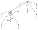
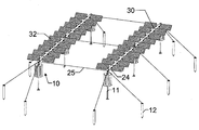
도 1은 본 발명에 따른 2개의 요소를 갖는 재생 가능한 소스로부터 에너지 생산용 시스템을 도시하고 있다.
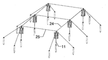
도 2는 본 발명에 따른 2개의 요소를 갖는 재생 가능한 소스로부터 에너지 생산용 시스템을 도시하고 있다.
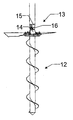
도 3은 본 발명에 따른 지면에 지지 기둥(pole) 및 끈을 고정하기 위한 구조체를 도시하고 있다.
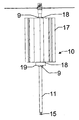
도 4는 본 발명에 따른 지지 기둥 상에 장착된 풍력 발전기의 정면도를 도시하고 있다.
도 5는 본 발명에 따른 지지 기둥 상에 장착된 풍력 발전기의 사시도를 도시하고 있다.
도 6은 본 발명에 따른 풍력 발전기의 절반-플랜지를 도시하고 있다.
도 7은 본 발명에 따른 시스템의 케이블 접속 시스템의 상세의 분해도를 도시하고 있다.
도 8은 본 발명에 따른 시스템의 슬라이드 가능한 확장 조인트의 상세의 분해도를 도시하고 있다.
도 9는 조합형 풍력 및 태양 에너지 생산 시스템을 도시하고 있다.
도 10은 터빈 고정 시스템을 통한 단면을 도시하고 있다.
도 11은 전기 발전기를 포함하는 터빈 고정 시스템을 통한 섹션을 도시하고 있다.
도 12는 지지 기둥에 풍력 기둥을 고정하기 위한 시스템을 도시하고 있다.Figure 1 shows a system for energy production from a renewable source having two elements according to the present invention.
Figure 2 shows a system for energy production from a renewable source having two elements according to the present invention.
Figure 3 illustrates a structure for securing support poles and straps to the ground according to the present invention.
Figure 4 shows a front view of a wind turbine mounted on a support column according to the invention.
Figure 5 shows a perspective view of a wind turbine mounted on a support column according to the invention.
Figure 6 shows a half-flange of a wind turbine according to the invention.
Figure 7 shows an exploded view of the details of the cable connection system of the system according to the invention.
Figure 8 shows an exploded view of the details of a slidable expansion joint of the system according to the invention.
Figure 9 shows a combined wind power and solar energy production system.
Figure 10 shows a cross section through a turbine fixing system.
Figure 11 shows a section through a turbine fixing system including an electric generator.
Figure 12 shows a system for securing a wind column to a support column.
첨부 도면을 참조하면, 본 발명에 따른 재생 가능한 소스로부터 에너지 생산용 시스템은 텐소구조체(tensostructure)에 의해 지지된 특히 수직축의 복수의 풍력 발전기(10)를 포함한다.Referring to the accompanying drawings, a system for producing energy from renewable sources according to the present invention comprises a plurality of
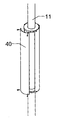
각각의 풍력 발전기(10)는 3 내지 4 mm의 두께를 갖는 약 10 내지 12 cm의 직경의 철 지지 기둥(11)에 의해 지지된다.Each
지지 기둥(11)은 끈의 망형 구조에 의해 적소에 유지된다.The
지지 기둥(11) 및 끈은 바람직하게는 지면에 놓여 있는 포스트(12)에 의해 지면에 고정된다. 포스트(12)는 지면 내에 삽입된 2 내지 3 m 및 약 30 cm의 직경의 콘크리트 튜브로 이루어진다.The
지지 기둥(11)은 이들의 베이스에 위치된 결합점(13)에 의해 포스트(12)에 고정된다.The
기초는 유리하게는 지면 내로 삽입된 포스트(12) 또는 현장에서 형성된 마이크로-파일(micro-pile), 즉 실질적으로 지면 내에 특정 깊이에 형성된 콘크리트의 플러그로 이루어진다.The base is advantageously made of a
포스트(12)는 천공 수직 플레이트(14)를 포함하는 결합점(13)을 그 상부에 구비한다. 지지 기둥(11)은 바람직하게는 플레이트(14)와 협동하는 2개의 이격된 천공 수직 플레이트(15)로 그 베이스에서 종료한다. 플레이트(14)는 플레이트(15) 내에 삽입된다.The
핀(16)이 플레이트(14, 15)의 서로 대면하는 구멍을 통해 삽입되어 지지 기둥(11)이 지지 기둥(11)의 축에 평행한 축선을 중심으로 회전할 수 있게 한다. 따라서, 결합점(13)은 힌지를 형성한다.The
각각의 풍력 발전기(10)는 예를 들어 지지 기둥(11)에 동축으로 위치된 사보니스(Savonius)형의 수직축의 터빈(17)을 포함한다. 터빈(17)은 예를 들어 2 m 높이이고, 1 m의 직경을 갖는다.Each
터빈(17)은 지지 기둥(11) 상에 장착을 위한 중앙 종방향 관통 구멍을 갖는다.The turbine (17) has a central longitudinal through hole for mounting on the support post (11).
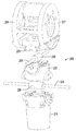
일 단부에서 전기 발전기(19)를 또한 포함한다. 터빈(17)을 지지 기둥(11)에 고정하기 위해, 2개의 절반 플랜지(9)가 사용되고, 그에 나사 결합되는 데, 즉 터빈(17)을 기둥(11)에 고정하는 하나의 상부 플랜지 및 하나의 하부 플랜지가 사용된다. 각각의 쌍의 절반 플랜지(9)는 터빈(17)이 회전할 수 있게 하는 베어링(18)을 위한 지지체로서 작용한다. 바람직하게는, 3개 또는 4개의 구조체(40)가 상기 베어링(18)에 고정되어 윈드 블레이드를 형성하는 이들 바람-타격면을 규정하여 적소에 유지한다. 이들 가요성 표면은 인장에 의해 형상이 유지된다.And also includes an
이러한 인장은 블레이드 표면에 대한 대향하는 상기 지지 구조체, 제1 중앙부에 대한 상부 및 하부에 대한 제2 중앙부 사이의 거리를 순서대로 수정함으로써 성취된다. 인장은 중앙 링 내에 삽입된 적절한 나사를 조정함으로써 인가된다.This tension is achieved by sequentially modifying the distance between the opposing support structure against the blade surface, the second central portion for the upper and lower portions relative to the first central portion. The tension is applied by adjusting the appropriate screws inserted in the center ring.
각각의 쌍의 절반 플랜지(9)는 적어도 3개의 등간격 반경방향 나사에 의해 고정된 지지 기둥의 외경보다 약간 큰 직경의 링을 생성하고, 이는 링이 기둥에 결합될 수 있게 하고 기둥의 임의의 비선형성이 보상될 수 있게 한다. 이는 완벽히 선형일 필요는 없는 기둥이 사용될 수 있게 하고 따라서 특정 공차 내의 이들의 선형성을 보장하기 위해 고가의 기둥 가공을 회피한다.Each pair of
이 방식으로 고정된 링은 동축 고정점이 특정 한계 이내로 지지 기둥의 선형성에 독립적으로 얻어질 수 있게 한다.Fixed rings in this way allow coaxial fixation points to be obtained independently of the linearity of the support columns within certain limits.
이들 링의 조립은 링을 기둥에 고정하는 나사의 조임 중에 이들을 동축으로 유지하는 링에 외부에서 고정된 간단한 제거 가능한 지지 구조체에 의해 간단화된다.The assembly of these rings is simplified by a simple removable support structure fixed externally to the ring which coaxially holds them during tightening of the screws that secure the ring to the column.
터빈(17)은 상부 또는 하부 링(9) 부근에서, 기둥(11) 상에 직접 장착된 원환형(toroidal type)의 전기 발전기(19)를 포함한다. 특히, 영구 자석(41)이 베어링(18)에 고정되어, 블레이드의 회전에 따라 대응 링(9)에 접속된 고정자의 권선(42) 내에 전기장을 유도하여, 전체 다상 링 발전기를 형성한다.The
고정 요소(또는 연결 크라운)(29)가 지지 기둥(11)의 상단부에 고정된다.A fixing element (or connecting crown) 29 is fixed to the upper end of the
고정 요소(29)는 기둥(11)에 고정을 위한 하부 부분(21), 중간 부분(22) 및 상부 부분(23)을 제시한다.The
시트가 하부 부분(21)과 중간 부분(22) 사이에서 케이블(24)을 위해 제공된다.A seat is provided for the
중간 부분(22)과 상부 부분(23) 사이에는, 케이블(24)에 수직으로 배치된 케이블(25)을 위한 시트가 제공된다.Between the
따라서, 고정 요소(29)는 예를 들어 기둥(11)의 상부에 장착되고 2개의 서로 수직인 긴장된 금속 케이블(24, 25)에 의해 횡단될 수 있게 하도록 형성된다.Thus, the securing
본질적으로, 2개의 긴장된 금속 케이블(24, 25)은 고정 요소(29)의 구성요소 내에 합체된다.In essence, the two
부분들(21, 22, 23)은 나사에 의해 함께 결합된다. 이전에, 잠금 슬리브(26)(케이블 직경을 증가시킴)가 설계에 의해 스케쥴링된 치수 설정에 따라, 큰 정밀도로 사전 결정된 거리에서 공장에서 케이블에 적용되어 그 위에 크림프된다. 이 방식으로, 이들 슬리브는 슬리브의 위치가 큰 정밀도로 지지 튜브(11) 사이의 거리를 미리 규정하기 때문에 일종의 조립 템플레이트를 형성한다.The
하부 부분(21), 중간 부분(22) 및 상부 부분(23)에 위치된 케이블(24, 25)을 위한 시트가 예를 들어 잠금 슬리브(26)를 보유하는 것을 가능하게 하도록 형성된다.A seat for the
따라서, 케이블은 기둥을 적소에 지지할 뿐만 아니라 큰 정밀도로 정확한 거리 이격하여 적소에 이들 기둥을 유지하는 데 사용되어, 따라서 기둥의 상부들 사이의 거리의 임의의 조정을 회피한다. 이 시스템은 비용을 절감하고, 지지 기둥의 조립을 간단화하고, 높은 정밀도를 보장한다.Thus, the cable is used not only to support the column in place, but also to maintain these columns in place at a precise distance and with great precision, thus avoiding any adjustment of the distance between the tops of the column. This system reduces costs, simplifies assembly of the support posts, and ensures high accuracy.
2개의 서로 수직인 케이블(25, 25)이 각각의 기둥(11)에 도달한다. 측방향 기둥을 취급하면, 케이블이 포스트(12)에서 지면에 고정된다. 중간 기둥을 취급하면, 케이블은 다음의 기둥으로 진행한다.Two
6개의 기둥(11)을 갖는 발전소에 대해, 18 mm 직경의 강철 케이블이 사용된다.For a power plant having six
본 발명의 특히 유리한 실시예에서, 고정 요소(29)의 상부 부분(23) 위에 그리고 그 측면에는 튜브(30)에 고정 요소를 고정하는 나사를 위해 요구된, 다수의 구멍을 포함하는 2개의 플랜지가 제공된다.In a particularly advantageous embodiment of the present invention, on the
하나의 플랜지(27)가 고정 요소(29)를 튜브(30)에 고정(지지)하기 위해 사용되고, 제1 플랜지에 대향하는 다른 플랜지(28)가 제1 튜브(30)와 일렬로 다른 인접한 튜브(30)에 고정 요소(29)를 고정(지지)하는 데 사용된다. 이 방식으로, 튜브(30)의 연속적인 열이 형성될 수 있다.One
수평으로 위치된 튜브(30)는 그 자신의 축선을 중심으로 회전할 수 있다. 이러한 메인 튜브에는 이 튜브(30)에 수직으로 고정되고 베어링에 의해 그 자신의 축 둘레로 회전하는 것이 가능한 복수의 보조 튜브(31)가 연결된다.The horizontally positioned
태양 에너지 집열 패널(32)이 각각의 보조 튜브(31)에 고정된다.The solar
메인 튜브(30)는 바람직하게는 압출 알루미늄(감소된 중량)으로 제조되고, 12 mm 길이이고, 약 30 내지 40 cm의 직경을 갖는 내부 중공형이다.The
보조 튜브(31)는 메인 튜브의 양 측면에서 플랜지로 종료하여 패널(32)이 나사에 의해 장착되고 탈착될 수 있게 한다.The
메인 튜브(30)는 끈의 망형 구조에 의해 적소에 유지된 2개의 지지 기둥(11)에 그 단부에서 고정된다.The
2개의 서로 정렬된 메인 튜브(30)에 대해, 2개의 측방향 지지 기둥(11) 및 단지 하나의 중간 지지 기둥(11)만이 요구된다.For two aligned
메인 튜브(30)의 일 단부에는, 튜브에 적합하게 고정된 모터가 제공되고, 그 기어휠은 고정 요소(29)에 고정된 치형부가 있는 반원(또는 치형부가 있는 휠)에 맞물린다. 이 모터는 그 축 둘레로 메인 튜브(30)를 회전시킨다.At one end of the
메인 튜브(30)의 더 내부에는, 보조 튜브(31)에 고정된 액슬(axle)과 고정하여 피니언을 회전시키는 래크를 구동하는 다른 모터가 존재한다. 이 구조체는 메인 튜브(30)에 고정된 보조 튜브의 각각의 쌍에 대해 반복된다.Further inside the
전술된 해결책에 대한 대안으로서, 기어휠은 풀리 및 벨트(또는 체인)를 갖는 래크로 대체될 수 있다.As an alternative to the above-mentioned solution, the gear wheel may be replaced by a rack having a pulley and a belt (or chain).
메인 튜브(30)의 다른 단부에서, 그 확장을 가능하게 하기 위한 신축식 요소를 갖고 구성된 슬라이드 가능 확장 조인트(33)가 위치된다.At the other end of the
일 신축식 요소(34)가 전기 발전기(29)의 플랜지에 고정되고, 다른 신축식 요소(35)가 메인 튜브(30)에 고정된다. 2개의 신축식 요소는 폴리테트라플루오로에틸렌(PTFE) 링(36)에 의해 분리된다. 조립 중에, 슬라이드 가능 단부는 예를 들어 최대 확장 및 최대 수축을 가능하게 하기 위해 지지 구조체에 고정된다.One
확장 조인트(33)는 고정 요소인 지지점 상에 베어링 없이 메인 튜브(30)가 열 팽창에 의해 길어지게 하거나 그 반대가 되게 하고, 고정 요소가 고정점에서 특정 이동의 탄성을 가질 수 있게 하여, 케이블의 탄성을 이 방식으로 보상한다.The
메인 튜브(30)는 하중 지탱형이기 때문에, 그 자중, 내부 링크장치의 중량, 패널이 연결되어 있는 회전 샤프트의 중량 및 패널의 중량을 지지한다. 튜브의 기계적 특성은 예를 들어 샤프트의 위치에 독립적으로 풍력 및 눈(snow)의 하중을 견디는 것이다.Since the
다양한 패널(32) 및/또는 터빈(17)을 위한 전기 접속 케이블이 메인 튜브(30) 내부에 위치되고, 이에 의해 생성된 전류를 운반한다.An electrical connection cable for the
메인 튜브(30) 내에 일체화된 팔로워용 제어 시스템은 패널을 태양을 향해 배향된 상태로 계속 유지할 수 있게 하여, 시간 및 날짜, 지리학적 설치 좌표 및 지면에 평행한 메인축의 북쪽으로의 배향에 기초하는 알고리즘에 따라, 천체 역학의 예측성으로부터 유도되는 공지의 기술에 의해, 태양이 패널의 집열면에 수직이 되게 한다.The control system for the follower integrated into the
각각의 메인 튜브(30)는 튜브 자체 내에 일체화된 제어 시스템과, 가까운 메인 튜브(30)와 통신하는 것이 가능한 수신기/송신기를 포함한다.Each
제어 시스템은 바람직하게는 지그비(ZigBee)형의 수신기-송신기를 구비하고, 이 수신기-송신기에 의해 다수의 발전기 및 하나 이상의 제어 센터로 이루어진 네트워크 내에서 통신하는 것이 가능하다. 각각의 수신기-송신기는 그 자신의 메시지를 직접 통신하거나 가까운 노드로부터 수신된 메시지를 재전송하는 것이 가능한 네트워크 내의 노드를 형성한다. 수신기-송신기의 작동 반경은 예를 들어 가장 가까운 수신기-송신기와 통신하는 것이 가능해야 할 뿐만 아니라, 이들 중 하나 이상의 고장의 경우에 더 멀리 있는 수신기-송신기와 통신하는 것이 가능해야 한다. 이 목적으로, 각각의 수신기-송신기의 작동 반경은 메인 튜브(30)의 길이의 적어도 4배일 것이다.The control system preferably comprises a receiver-transmitter of the ZigBee type and is capable of communicating within the network of multiple generators and one or more control centers by means of this receiver-transmitter. Each receiver-transmitter forms a node in the network that is capable of directly communicating its own message or retransmitting a message received from a nearby node. The operating radius of the receiver-transmitter must be capable of communicating with, for example, the nearest receiver-transmitter, as well as communicating with a more distant receiver-transmitter in the event of one or more of these failures. For this purpose, the operating radius of each receiver-transmitter will be at least four times the length of the
통상의 경우는 균형 문제점을 회피하기 위해 일 측에 5개의 패널 및 제1 위치에 대향하는 위치에 메인 튜브(30)의 다른측에 5개의 패널을 포함하는 높이 5 m의 기둥을 갖는 12 m 이격된 평행한 열로 길이 12 m의 메인 튜브(30)를 갖는 팔로워(32) 및 터빈(17)과 조합된 구조체의 사용일 수 있고, 이들은 약 1.5 m 이격된 1m×2m(또는 심지어 그 이상)의 크기이다. 이 구성에 의해, 발전소 아래로 통과하는 것이 가능한 농기계의 크기 또는 농작물의 유형에 대한 제한이 없다.In order to avoid balance problems in the normal case, there are five panels on one side and a 12 m spacing with 5 m height columns including five panels on the other side of the
설비를 높이 장착함으로써, 발전기 및 전기 시스템은 지면으로부터 멀리 유지되어, 따라서 작업원에 대한 안전 레벨을 증가시키고 범람 가능한 또는 습지의 토지가 사용될 수 있게 한다.By elevating the installation, the generator and the electrical system are kept away from the ground, thus increasing the level of safety to the operator and allowing the use of flooded or wetland land.
끈을 갖는 구조체는 지면 내에 삽입될 마이크로-파일 또는 포스트를 사용함으로써 단지 제한된 기초 작업만을 갖고 성취될 수 있어, 따라서 지면 위에 위치된 전통적인 추적 장치(tracker)에 의해 요구된 위압적인 보강된 콘크리트 기초 작업을 회피한다.The structure with the rope can be achieved with only a limited foundation work by using micro-files or posts to be inserted into the ground so that the overburdened reinforced concrete foundation work required by the traditional tracker located above the ground .
포스트의 열이 놓이고 포스트의 열을 횡방향으로 함께 연결하는 케이블이 포스트의 상부를 통해 통과할 때(케이블은 이어서 포스트의 열의 시작부 및 종료부에서 지면에 잠금됨), 이 해결책은 간단한 레버 시스템을 사용하여 기둥의 베이스에서 피벗부 상에서 이들을 매우 용이하게 회전시킴으로써 기둥이 지면으로부터 상승될 수 있게 한다. 기둥과 기초 사이의 조인트는 기둥이 교체될 수 있게 하도록 퇴피될 수 있고 발전소의 수명의 종료시에 구조체가 분해될 수 있고 기초가 지면으로부터 용이하게 제거될 수 있게 하는 피벗부로 이루어진다. 기초는 지면으로부터 수직으로 이를 퇴피하는 승강 시스템에 그 단부에서 고정된 링에서 결합된다.As the cables of the posts are placed and the cables connecting the rows of posts laterally together pass through the top of the posts (the cables are then locked to the ground at the beginning and end of the row of posts) Using the system, the pillars can be raised from the ground by rotating them very easily on the pivot portion at the base of the column. The joint between the column and the foundation consists of a pivot which can be retracted to allow the column to be replaced and which allows the structure to be disassembled at the end of the life of the power plant and the foundation to be easily removed from the ground. The bases are joined at a fixed ring at their ends to a lifting system that retracts them vertically from the ground.
발전소는 모든 이동축을 따라 균형을 이루고 따라서 그 이동을 위해 최소의 힘을 필요로 한다. 이는 낮은 에너지 소비 및 더 경량의 기계적 부재를 야기한다.Power plants are balanced along all moving axes and thus require minimal effort for their movement. This results in low energy consumption and lighter mechanical absence.
본 발명의 지지 구조체는 이는 기초 지면 상에 상당한 충격을 주고 발전소 작동 수명의 종료시에 제거가 곤란한 보강된 콘크리트 기초 작업을 필요로 하지 않는다.The support structure of the present invention does not require a reinforced concrete foundation operation that gives significant impact on the foundation ground and is difficult to remove at the end of the plant operating life.
연구된 시스템의 특성에 의해, 터빈 설비는 특히 간단하고 경제적이다. 이 터빈 설비는 기둥의 베이스의 힌지 연결에 기초하는 설치 시스템에 의해, 단지 그 후에 직립 위치로 배치될 설치 중에 지면에 놓인 기둥을 유지하는 새로운 구조 설비의 경우에 그리고 상기 힌지가 고정 링 및 터빈의 원환형 구성요소를 삽입하는 것이 가능할 필요가 있는 양만큼 기둥이 힌지로부터 분리될 수 있게 하는 미리 존재하는 구조체의 경우에 지면 상에 완전히 발생한다. 이 양태는 상기 터빈 구성요소를 교체하기 위한 임의의 유지보수 작업을 보장하는 데 기본적인데, 이 동작은 연속적인 텐소구조체를 탈착할 필요가 없기 때문에 경제적이다(소위 기둥의 상부에 위치된 소켓을 통해 통과하는 연속적인 케이블로 이루어지기 때문에).Due to the characteristics of the system studied, the turbine installation is particularly simple and economical. This turbine installation is achieved by means of an installation system based on the hinge connection of the base of the column and in the case of a new structural arrangement which keeps the column lying on the ground during installation which is then only to be placed in an upright position, It occurs completely on the ground in the case of a pre-existing structure that allows the column to be separated from the hinge by an amount that it is necessary to insert the annular component. This aspect is essential in ensuring any maintenance work for replacing the turbine components, which is economical since it is not necessary to detach the continuous tensor structure (through a socket located at the top of the so-called column) Because it is made up of continuous cables passing through).
언급된 바와 같이, 기둥은 블레이드 상에 바람에 의해 유도되어 이에 의해 지지 포스트 상에 전달된 막대한 굴곡 응력을 견딜 필요가 없고, 다라서 소형 치수의 강철 또는 심지어 목재의 일반적인 기둥이 사용될 수 있다.As mentioned, the posts do not have to withstand the enormous bending stresses that are induced by the wind on the blades and thereby transmitted on the support posts, so that small sized steel or even common columns of wood can be used.
더욱이, 기둥은 회전하지 않아야 하고 대신에 회전하는 기둥 자체 상에 장착된 터빈이고, 따라서 기둥은 매우 일반적인 기둥이다.Moreover, the column should not rotate, but instead is a turbine mounted on the rotating column itself, so the column is a very common column.
약 6 m의 현재의 경우에서와 같은 매우 긴 기둥에 대해, 2개 또는 심지어 3개의 터빈이 추가의 고정 링(9) 또는 추가의 베어링(18)을 사용하여 기둥 상에서 서로 중첩하여 장착될 수 있다.For very long columns, as in the present case of about 6 m, two or even three turbines can be mounted on top of each other on the columns using an
사용된 재료 및 치수는 요구 및 기술 분야에 따라 선택될 수 있다. 이 방식으로 고려되는 태양열 트랙커는 본 발명의 개념의 범주 내에 모두 있는 수많은 수정 및 변형에 민감하고, 더욱이 모든 상세는 기술적으로 등가의 요소에 의해 교체될 수 있다.The materials and dimensions used may be selected according to the needs and technical fields. The solar tracker considered in this manner is susceptible to numerous modifications and variations that are all within the scope of the inventive concept, and all details may be replaced by technically equivalent elements.
Claims (9)
수직으로 위치된 제1 기둥(pole) 및 제2 기둥을 포함하는 지지 구조체; 및
상기 제1 기둥 상에 위치된 수직축의 풍력 발전기와 상기 제2 기둥 상에 위치된 수직축의 풍력 발전기
를 포함하며, 상기 제1 기둥 및 상기 제2 기둥은 각각 그 정상부에 위치된 연결 요소를 포함하고,
상기 연결 요소는 상기 제1 기둥 및 상기 제2 기둥에 고정될 하부 부분을 포함하고,
상기 연결 요소는 중간 부분 및 상부 부분을 포함하며,
제1 케이블용 제1 시트가 상기 하부 부분과 상기 중간 부분 사이에 위치되고, 제2 케이블용 제2 시트가 상기 중간 부분과 상기 상부 부분 사이에 위치되며,
상기 제1 케이블 및 상기 제2 케이블은 서로 수직으로 위치되고,
상기 제1 케이블 및 상기 제2 케이블의 단부들은 지면 내에 고정된 포스트(post)에 의해 지면에 고정되고,
상기 제1 기둥 및 상기 제2 기둥은 지면에 고정된 포스트에 힌지에 의해 각각 고정되고,
상기 풍력 발전기는 상기 제1 기둥 및 상기 제2 기둥 상에 장착을 가능하게 하기 위한 종방향 중앙 관통 구멍을 갖고,
상기 풍력 발전기는 상기 풍력 발전기를 위한 하부 제1 잠금링 및 상기 풍력 발전기를 위한 상부 제2 잠금링을 포함하고,
상기 풍력 발전기가 회전할 수 있게 하기 위해 상기 제1 링 및 상기 제2 링에 베어링이 각각 연계되는 것인 에너지 생산 시스템.A system for producing energy from a renewable source comprising:
A support structure including a vertically positioned first pole and a second post; And
A vertical axis wind turbine positioned on the first column and a vertical axis wind turbine positioned on the second column,
Wherein the first post and the second post each include a connecting element located at its top,
The connecting element includes a lower portion to be fixed to the first post and the second post,
The connecting element comprising an intermediate portion and an upper portion,
A first sheet for the first cable is located between the lower portion and the middle portion and a second sheet for the second cable is located between the middle portion and the upper portion,
The first cable and the second cable are positioned perpendicular to each other,
The ends of the first cable and the second cable are fixed to the ground by a post fixed in the ground,
The first pillar and the second pillar are respectively fixed to a post fixed to the ground by a hinge,
The wind power generator has a longitudinal center through hole for enabling mounting on the first pillar and the second pillar,
The wind turbine including a lower first lock ring for the wind turbine and an upper second lock ring for the wind turbine,
Wherein bearings are associated with the first ring and the second ring, respectively, so that the wind turbine can rotate.
상기 메인 튜브에 직교하게 이동 가능 방식으로 고정된 복수의 보조 튜브; 및
상기 보조 튜브의 각각에 고정되는 태양 에너지 집열 패널
을 더 포함하는 것인 에너지 생산 시스템.2. The apparatus of claim 1, further comprising: a load-bearing main tube rotatable about its axis and having ends coupled to an upper end of the first column and the second column;
A plurality of auxiliary tubes movably fixed to the main tube in a perpendicular manner; And
And a solar energy collecting panel
Further comprising: < / RTI >
Applications Claiming Priority (3)
| Application Number | Priority Date | Filing Date | Title |
|---|---|---|---|
| IT000048A ITBG20110048A1 (en) | 2011-11-25 | 2011-11-25 | ENERGY PRODUCTION SYSTEM FROM RENEWABLE SOURCES |
| ITBG2011A000048 | 2011-11-25 | ||
| PCT/IB2012/002492 WO2013076573A1 (en) | 2011-11-25 | 2012-11-26 | System for energy production from renewable sources |
Publications (1)
| Publication Number | Publication Date |
|---|---|
| KR20140105487A true KR20140105487A (en) | 2014-09-01 |
Family
ID=45370547
Family Applications (1)
| Application Number | Title | Priority Date | Filing Date |
|---|---|---|---|
| KR1020147017315A Ceased KR20140105487A (en) | 2011-11-25 | 2012-11-26 | System for energy production from renewable sources |
Country Status (26)
| Country | Link |
|---|---|
| US (1) | US10138874B2 (en) |
| EP (1) | EP2783105B1 (en) |
| JP (1) | JP6248043B2 (en) |
| KR (1) | KR20140105487A (en) |
| CN (1) | CN104040167B (en) |
| AP (1) | AP2014007706A0 (en) |
| AU (1) | AU2012342189A1 (en) |
| BR (1) | BR112014012462A2 (en) |
| CA (1) | CA2856498C (en) |
| CL (1) | CL2014001365A1 (en) |
| CO (1) | CO7020887A2 (en) |
| CU (1) | CU20140057A7 (en) |
| EA (1) | EA201491037A1 (en) |
| EC (1) | ECSP14004229A (en) |
| ES (1) | ES2612191T3 (en) |
| IL (1) | IL232714A0 (en) |
| IN (1) | IN2014MN00950A (en) |
| IT (1) | ITBG20110048A1 (en) |
| MA (1) | MA35751B1 (en) |
| MX (1) | MX2014006224A (en) |
| PE (1) | PE20142058A1 (en) |
| PH (1) | PH12014501128A1 (en) |
| PT (1) | PT2783105T (en) |
| TN (1) | TN2014000219A1 (en) |
| WO (1) | WO2013076573A1 (en) |
| ZA (1) | ZA201403706B (en) |
Families Citing this family (20)
| Publication number | Priority date | Publication date | Assignee | Title |
|---|---|---|---|---|
| US9347332B2 (en) * | 2011-07-28 | 2016-05-24 | Mitsui Engineering & Shipbuilding | Dynamo with columnar oscillator |
| DE102012002551A1 (en) | 2012-02-09 | 2013-08-14 | Fraunhofer-Gesellschaft zur Förderung der angewandten Forschung e.V. | Process for the simultaneous cultivation of crops and energetic use of sunlight |
| US10890161B1 (en) * | 2014-08-20 | 2021-01-12 | Bhaskar R Vemuri | Embedded electrical energy platform |
| SE539182C2 (en) * | 2015-07-02 | 2017-05-02 | Seatwirl Ab | Floating wind energy harvesting apparatus with replaceable energy converter |
| JP6732940B2 (en) * | 2016-05-23 | 2020-07-29 | レム テック ソシエタ ア レスポンサビリタ リミタータ | System for covering flat surfaces |
| IT201700042816A1 (en) | 2017-04-19 | 2018-10-19 | Rem Tec S R L | Plant for the production of solar energy that can be installed on agricultural land. |
| US10975839B2 (en) * | 2018-05-23 | 2021-04-13 | William Olen Fortner | Vertical axis wind turbines with V-cup shaped vanes, multi-turbine assemblies and related methods and systems |
| CN114375506A (en) | 2019-09-06 | 2022-04-19 | 日本放送协会 | Organic thin film, method for producing organic thin film, organic electroluminescent element, display device, lighting device, organic thin film solar cell, photoelectric conversion element, thin film transistor, coating composition, and material for organic electroluminescent element |
| US20230006159A1 (en) | 2019-09-06 | 2023-01-05 | Nippon Hoso Kyokai | Organic thin film, method for producing organic thin film, organic electroluminescent element, display device, lighting device, organic thin film solar cell, thin film transistor, photoelectric conversion element, coating composition and material for organic electroluminescent elements |
| EP4193462B1 (en) | 2020-08-05 | 2025-06-11 | Rem Tec S.R.L. | Electrical energy production plant that can be installed on structures and/or agricultural grounds |
| KR20230119132A (en) * | 2020-12-18 | 2023-08-16 | 렘 텍 에스.알.엘. | Solar energy production plant that can be installed on farmland |
| KR102863172B1 (en) | 2020-12-18 | 2025-09-22 | 가부시키가이샤 닛폰 쇼쿠바이 | Organic electroluminescent device, display device, lighting device, method for manufacturing organic electroluminescent device |
| IL305244A (en) * | 2021-02-22 | 2023-10-01 | Rem Tec S R L | A plant for generating electricity and treating agricultural land |
| IT202100011960A1 (en) | 2021-05-10 | 2022-11-10 | Rem Tec S R L | Plant for the production of electricity including a tensile structure. |
| WO2023146507A2 (en) * | 2022-01-31 | 2023-08-03 | Наталия Мыхайливна МЭЛЬНЫК | Method for growing industrial hemp in a polyculture with medicinal plants and in conjunction with solar energy production |
| EP4559087A1 (en) * | 2022-07-22 | 2025-05-28 | Borracci, Nicola | Pole cover with photovoltaic panel support |
| IT202200017877A1 (en) | 2022-08-31 | 2024-03-02 | Rem Tec S R L | Electricity production plant located on agricultural land with monitoring of crops on that land. |
| US12375023B2 (en) | 2022-11-17 | 2025-07-29 | Solargik, Ltd. | Adjustable supporting structure for one or more photovoltaic panels |
| IT202300001320A1 (en) | 2023-01-27 | 2024-07-27 | Rem Tec S R L | ELECTRICITY PRODUCTION PLANT INCLUDING A TENSILE STRUCTURE INCLUDING GROUND SUPPORTS. |
| WO2025023185A1 (en) | 2023-07-21 | 2025-01-30 | 株式会社日本触媒 | Thin film-modified electrode and organic element using same |
Family Cites Families (26)
| Publication number | Priority date | Publication date | Assignee | Title |
|---|---|---|---|---|
| US4023368A (en) * | 1975-08-26 | 1977-05-17 | Kelly Donald A | High density-third dimension geometry solar panels |
| US4218183A (en) * | 1978-07-31 | 1980-08-19 | Dall Winther Dennis P | Windmill |
| US4224082A (en) * | 1979-06-26 | 1980-09-23 | Independent Power Company, Inc. | Multi-functional solar collector pole |
| US4486143A (en) * | 1982-09-01 | 1984-12-04 | Mcvey Paul W | Turbine-type wind machine |
| JPS6312583A (en) * | 1986-07-02 | 1988-01-19 | 株式会社日立製作所 | Winding machine for elevator |
| JP2000008407A (en) * | 1998-06-23 | 2000-01-11 | Mitsubishi Heavy Ind Ltd | Foreign matter removal device and soil improvement device equipped therewith |
| US6784566B2 (en) * | 2001-01-25 | 2004-08-31 | Robert Nason Thomas | Coupled vortex vertical axis wind turbine |
| US6857846B2 (en) * | 2001-06-19 | 2005-02-22 | Lewis H. Miller | Stackable vertical axis windmill |
| JPWO2005111415A1 (en) * | 2004-05-13 | 2008-07-31 | 株式会社アイ・ピー・ビー | Vertical axis wind turbine support arm mounting structure and vertical axis wind turbine |
| WO2007021992A2 (en) * | 2005-08-12 | 2007-02-22 | Mariah Power Inc. | Low cost wind turbine |
| JP2007194178A (en) * | 2006-01-16 | 2007-08-02 | Sign Create:Kk | Lighting pillar for disaster prevention |
| DE102006010162A1 (en) * | 2006-02-28 | 2007-09-06 | Conergy Ag | Trackable frame for solar modules |
| JP3121915U (en) * | 2006-03-08 | 2006-06-01 | 三菱電機エンジニアリング株式会社 | Hybrid power generation system |
| US7811060B2 (en) * | 2006-03-13 | 2010-10-12 | Vanderhye Robert A | VAWT cluster and individual supporting arrangements |
| CN201068841Y (en) * | 2007-06-02 | 2008-06-04 | 刘建定 | Minisize wind energy solar energy complementary type generation device |
| US20090079197A1 (en) * | 2007-09-26 | 2009-03-26 | Hao-Wei Poo | Expandable apparatus for generating electric power using wind energy |
| ITVA20070075A1 (en) * | 2007-10-08 | 2009-04-08 | Sergio Biucchi | WIND AND PHOTOVOLTAIC HYBRID PLANT WITH VERTICAL BI-MA ROTOR CABLE WITH AXIS |
| US20090261595A1 (en) * | 2008-04-17 | 2009-10-22 | Hao-Wei Poo | Apparatus for generating electric power using wind energy |
| US8043499B2 (en) * | 2008-10-29 | 2011-10-25 | King Fahd University Of Petroleum And Minerals | Portable and autonomous desalination system |
| TWI356129B (en) * | 2008-12-03 | 2012-01-11 | Ind Tech Res Inst | A vertical axial wind-driven generator |
| WO2010071850A2 (en) * | 2008-12-19 | 2010-06-24 | Higher Dimension Materials, Inc. | Multi-rotor vertical axis wind turbine |
| IT1398598B1 (en) * | 2009-03-10 | 2013-03-08 | Dermotricos Srl | SOLAR ENERGY STATION SYSTEM |
| US8427000B2 (en) * | 2009-06-24 | 2013-04-23 | Alex Ignatiev | Dual-mode roadway turbines for energy generation from artificial pulsed vehicle wind and continuous ambient wind |
| US20110089698A1 (en) * | 2009-07-24 | 2011-04-21 | William Ahmadi | Combination solar and dual generator wind turbine |
| US20110025070A1 (en) * | 2009-07-31 | 2011-02-03 | Arnold Price | Utility grid vertical axis wind turbine system |
| DE102010005585A1 (en) * | 2010-01-22 | 2011-07-28 | Kellner, Peter, 36269 | Fastening device for fastening solar panel and/or wind-power plant, has tubular body equipped with support, where support provided for panel is used for connection with base and wind-power plant is arranged above fastening portion at body |
-
2011
- 2011-11-25 IT IT000048A patent/ITBG20110048A1/en unknown
-
2012
- 2012-11-26 IN IN950MUN2014 patent/IN2014MN00950A/en unknown
- 2012-11-26 KR KR1020147017315A patent/KR20140105487A/en not_active Ceased
- 2012-11-26 CA CA2856498A patent/CA2856498C/en active Active
- 2012-11-26 EP EP12806663.6A patent/EP2783105B1/en active Active
- 2012-11-26 US US14/360,313 patent/US10138874B2/en not_active Expired - Fee Related
- 2012-11-26 BR BR112014012462A patent/BR112014012462A2/en not_active IP Right Cessation
- 2012-11-26 WO PCT/IB2012/002492 patent/WO2013076573A1/en not_active Ceased
- 2012-11-26 AU AU2012342189A patent/AU2012342189A1/en not_active Abandoned
- 2012-11-26 PT PT128066636T patent/PT2783105T/en unknown
- 2012-11-26 AP AP2014007706A patent/AP2014007706A0/en unknown
- 2012-11-26 EA EA201491037A patent/EA201491037A1/en unknown
- 2012-11-26 ES ES12806663.6T patent/ES2612191T3/en active Active
- 2012-11-26 JP JP2014542949A patent/JP6248043B2/en not_active Expired - Fee Related
- 2012-11-26 CN CN201280065894.1A patent/CN104040167B/en not_active Expired - Fee Related
- 2012-11-26 MX MX2014006224A patent/MX2014006224A/en unknown
- 2012-11-26 PE PE2014000743A patent/PE20142058A1/en not_active Application Discontinuation
-
2014
- 2014-05-19 TN TNP2014000219A patent/TN2014000219A1/en unknown
- 2014-05-20 IL IL232714A patent/IL232714A0/en unknown
- 2014-05-20 PH PH12014501128A patent/PH12014501128A1/en unknown
- 2014-05-21 ZA ZA2014/03706A patent/ZA201403706B/en unknown
- 2014-05-22 CO CO14110837A patent/CO7020887A2/en unknown
- 2014-05-23 CL CL2014001365A patent/CL2014001365A1/en unknown
- 2014-05-23 CU CU2014000057A patent/CU20140057A7/en unknown
- 2014-06-09 EC ECIEPI20144229A patent/ECSP14004229A/en unknown
- 2014-06-25 MA MA37161A patent/MA35751B1/en unknown
Also Published As
| Publication number | Publication date |
|---|---|
| ECSP14004229A (en) | 2015-06-30 |
| WO2013076573A1 (en) | 2013-05-30 |
| TN2014000219A1 (en) | 2015-09-30 |
| PT2783105T (en) | 2017-02-01 |
| PH12014501128B1 (en) | 2014-08-04 |
| EA201491037A1 (en) | 2014-09-30 |
| US20140327244A1 (en) | 2014-11-06 |
| PE20142058A1 (en) | 2014-12-06 |
| IL232714A0 (en) | 2014-07-31 |
| IN2014MN00950A (en) | 2015-04-24 |
| JP2015503053A (en) | 2015-01-29 |
| CO7020887A2 (en) | 2014-08-11 |
| ES2612191T3 (en) | 2017-05-12 |
| JP6248043B2 (en) | 2017-12-13 |
| MX2014006224A (en) | 2015-03-03 |
| CU20140057A7 (en) | 2014-10-02 |
| BR112014012462A2 (en) | 2017-06-06 |
| EP2783105B1 (en) | 2016-10-26 |
| CA2856498A1 (en) | 2013-05-30 |
| AP2014007706A0 (en) | 2014-06-30 |
| ZA201403706B (en) | 2016-01-27 |
| US10138874B2 (en) | 2018-11-27 |
| ITBG20110048A1 (en) | 2013-05-26 |
| MA35751B1 (en) | 2014-12-01 |
| CN104040167B (en) | 2017-05-03 |
| CL2014001365A1 (en) | 2014-11-21 |
| PH12014501128A1 (en) | 2014-08-04 |
| EP2783105A1 (en) | 2014-10-01 |
| CA2856498C (en) | 2020-03-24 |
| CN104040167A (en) | 2014-09-10 |
| AU2012342189A1 (en) | 2014-06-12 |
Similar Documents
| Publication | Publication Date | Title |
|---|---|---|
| KR20140105487A (en) | System for energy production from renewable sources | |
| US10103685B2 (en) | Tracking photovoltaic solar system, and methods for installing or for using such tracking photovoltaic solar system | |
| US20110025070A1 (en) | Utility grid vertical axis wind turbine system | |
| US20110062717A1 (en) | Urility grid vertical axis wind turbine system | |
| US8967946B2 (en) | Modular wind-solar energy converting assembly | |
| US9046074B2 (en) | Split collar mountable wind turbine | |
| CN104904113A (en) | Supports for solar collection | |
| US20200195191A1 (en) | Solar tracking installation | |
| CN102349164A (en) | Solar energy collection system | |
| CN105553398A (en) | Solar bracket with adjustable angle | |
| KR100962558B1 (en) | Windbreak prevention device for solar generator | |
| AU2017203521A1 (en) | Solar tracking system | |
| KR20140005878U (en) | Solar tracker | |
| KR20100026912A (en) | Photovoltaic Power Plants Addressed to Wind Power Generators | |
| KR100882192B1 (en) | Solar Tracking Energy Generator | |
| GB2491853A (en) | Modular wind turbine system with repositionable turbines | |
| HK1198055A (en) | System for energy production from renewable sources | |
| KR20130026066A (en) | Merge power generation street light | |
| OA16989A (en) | System for energy production from renewable sources | |
| KR101967187B1 (en) | wind generator | |
| CN116648587A (en) | Device for producing solar energy capable of being installed on agricultural land | |
| RU196874U1 (en) | MODULAR WIND MAST MAST | |
| GB2508502A (en) | Modular wind turbine system | |
| KR101389985B1 (en) | Wind power generator increased generation efficiency as bucket type rotor blades | |
| JP2013033840A (en) | Attachment pedestal apparatus for solar cell panel and its installation method |
Legal Events
| Date | Code | Title | Description |
|---|---|---|---|
| PA0105 | International application |
Patent event date: 20140624 Patent event code: PA01051R01D Comment text: International Patent Application |
|
| PG1501 | Laying open of application | ||
| A201 | Request for examination | ||
| PA0201 | Request for examination |
Patent event code: PA02012R01D Patent event date: 20171110 Comment text: Request for Examination of Application |
|
| E902 | Notification of reason for refusal | ||
| PE0902 | Notice of grounds for rejection |
Comment text: Notification of reason for refusal Patent event date: 20190219 Patent event code: PE09021S01D |
|
| E601 | Decision to refuse application | ||
| PE0601 | Decision on rejection of patent |
Patent event date: 20190628 Comment text: Decision to Refuse Application Patent event code: PE06012S01D Patent event date: 20190219 Comment text: Notification of reason for refusal Patent event code: PE06011S01I |