KR20140109351A - 레이저를 사용한 다층 에어백 커버에 소정의 파단선을 형성하는 방법 - Google Patents
레이저를 사용한 다층 에어백 커버에 소정의 파단선을 형성하는 방법 Download PDFInfo
- Publication number
- KR20140109351A KR20140109351A KR1020140101844A KR20140101844A KR20140109351A KR 20140109351 A KR20140109351 A KR 20140109351A KR 1020140101844 A KR1020140101844 A KR 1020140101844A KR 20140101844 A KR20140101844 A KR 20140101844A KR 20140109351 A KR20140109351 A KR 20140109351A
- Authority
- KR
- South Korea
- Prior art keywords
- layer
- holes
- laser
- carrier
- airbag cover
- Prior art date
- Legal status (The legal status is an assumption and is not a legal conclusion. Google has not performed a legal analysis and makes no representation as to the accuracy of the status listed.)
- Granted
Links
Images


Classifications
-
- B—PERFORMING OPERATIONS; TRANSPORTING
- B60—VEHICLES IN GENERAL
- B60R—VEHICLES, VEHICLE FITTINGS, OR VEHICLE PARTS, NOT OTHERWISE PROVIDED FOR
- B60R21/00—Arrangements or fittings on vehicles for protecting or preventing injuries to occupants or pedestrians in case of accidents or other traffic risks
- B60R21/02—Occupant safety arrangements or fittings, e.g. crash pads
- B60R21/16—Inflatable occupant restraints or confinements designed to inflate upon impact or impending impact, e.g. air bags
- B60R21/20—Arrangements for storing inflatable members in their non-use or deflated condition; Arrangement or mounting of air bag modules or components
- B60R21/215—Arrangements for storing inflatable members in their non-use or deflated condition; Arrangement or mounting of air bag modules or components characterised by the covers for the inflatable member
- B60R21/2165—Arrangements for storing inflatable members in their non-use or deflated condition; Arrangement or mounting of air bag modules or components characterised by the covers for the inflatable member characterised by a tear line for defining a deployment opening
-
- B—PERFORMING OPERATIONS; TRANSPORTING
- B23—MACHINE TOOLS; METAL-WORKING NOT OTHERWISE PROVIDED FOR
- B23K—SOLDERING OR UNSOLDERING; WELDING; CLADDING OR PLATING BY SOLDERING OR WELDING; CUTTING BY APPLYING HEAT LOCALLY, e.g. FLAME CUTTING; WORKING BY LASER BEAM
- B23K26/00—Working by laser beam, e.g. welding, cutting or boring
- B23K26/02—Positioning or observing the workpiece, e.g. with respect to the point of impact; Aligning, aiming or focusing the laser beam
- B23K26/06—Shaping the laser beam, e.g. by masks or multi-focusing
- B23K26/0604—Shaping the laser beam, e.g. by masks or multi-focusing by a combination of beams
- B23K26/0613—Shaping the laser beam, e.g. by masks or multi-focusing by a combination of beams having a common axis
-
- B—PERFORMING OPERATIONS; TRANSPORTING
- B23—MACHINE TOOLS; METAL-WORKING NOT OTHERWISE PROVIDED FOR
- B23K—SOLDERING OR UNSOLDERING; WELDING; CLADDING OR PLATING BY SOLDERING OR WELDING; CUTTING BY APPLYING HEAT LOCALLY, e.g. FLAME CUTTING; WORKING BY LASER BEAM
- B23K26/00—Working by laser beam, e.g. welding, cutting or boring
- B23K26/36—Removing material
- B23K26/38—Removing material by boring or cutting
- B23K26/382—Removing material by boring or cutting by boring
- B23K26/389—Removing material by boring or cutting by boring of fluid openings, e.g. nozzles, jets
-
- B—PERFORMING OPERATIONS; TRANSPORTING
- B60—VEHICLES IN GENERAL
- B60R—VEHICLES, VEHICLE FITTINGS, OR VEHICLE PARTS, NOT OTHERWISE PROVIDED FOR
- B60R21/00—Arrangements or fittings on vehicles for protecting or preventing injuries to occupants or pedestrians in case of accidents or other traffic risks
- B60R21/02—Occupant safety arrangements or fittings, e.g. crash pads
- B60R21/16—Inflatable occupant restraints or confinements designed to inflate upon impact or impending impact, e.g. air bags
- B60R21/20—Arrangements for storing inflatable members in their non-use or deflated condition; Arrangement or mounting of air bag modules or components
- B60R21/201—Packaging straps or envelopes for inflatable members
-
- B—PERFORMING OPERATIONS; TRANSPORTING
- B60—VEHICLES IN GENERAL
- B60R—VEHICLES, VEHICLE FITTINGS, OR VEHICLE PARTS, NOT OTHERWISE PROVIDED FOR
- B60R21/00—Arrangements or fittings on vehicles for protecting or preventing injuries to occupants or pedestrians in case of accidents or other traffic risks
- B60R21/02—Occupant safety arrangements or fittings, e.g. crash pads
- B60R21/16—Inflatable occupant restraints or confinements designed to inflate upon impact or impending impact, e.g. air bags
- B60R21/20—Arrangements for storing inflatable members in their non-use or deflated condition; Arrangement or mounting of air bag modules or components
- B60R21/215—Arrangements for storing inflatable members in their non-use or deflated condition; Arrangement or mounting of air bag modules or components characterised by the covers for the inflatable member
- B60R21/2165—Arrangements for storing inflatable members in their non-use or deflated condition; Arrangement or mounting of air bag modules or components characterised by the covers for the inflatable member characterised by a tear line for defining a deployment opening
- B60R2021/21652—Arrangements for storing inflatable members in their non-use or deflated condition; Arrangement or mounting of air bag modules or components characterised by the covers for the inflatable member characterised by a tear line for defining a deployment opening the tearing being done or assisted by cutters
Landscapes
- Physics & Mathematics (AREA)
- Optics & Photonics (AREA)
- Engineering & Computer Science (AREA)
- Mechanical Engineering (AREA)
- Plasma & Fusion (AREA)
- Air Bags (AREA)
- Laser Beam Processing (AREA)
Abstract
Description
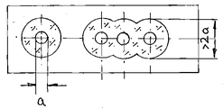
도 2는 본 발명에 따라 제조된 에어백 커버의 상면도의 개략적인 도면이다.
도 3은 제 1 실시예에 따른 두 개의 레이저의 광선의 측면도이다.
도 4는 제 2 실시예에 따른 두 개의 레이저의 광선의 측면도이다.
2: 지지층
3: 장식층
Claims (12)
- 지지층(2), 상기 지지층(2)의 물질보다 높은 밀도를 갖는 물질로 이루어진 캐리어층(1) 및 장식층(3)을 구비하는 다층의 에어백 커버에, 일정한 광선 직경(a)을 가지고 가우스(Gauss) 형태의 광선밀도 분포를 가지는 레이저를 사용하여 상기 장식층(3)에 일정한 간격을 둔 끝이 막힌 구멍 또는 미세 천공홀들을 형성함으로써 소정의 파단선(breaking line)을 형성하는 방법에 있어서,
상기 캐리어층(1)의 물질은 상기 끝이 막힌 홀들 및 미세천공홀들 사이의 간격으로 상기 파단선을 따라 광선직경(a)보다 상대적으로 더 큰 폭(b)에 걸쳐 완전히 제거되고, 상기 레이저는 상기 캐리어층(1)에 구비된 관통홀들을 통과하여 상기 이격된 끝이 막힌 홀들 및 미세천공홀들을 형성하며,
생성된 연소가스는 상기 관통홀들을 통해서 배출될 수 있는 것을 특징으로 하는 다층의 에어백 커버에 소정의 파단선을 형성하는 방법. - 제1항에 있어서, 상기 폭(b)은 상기 광선직경(a)의 두 배보다 큰 것을 특징으로 하는 다층의 에어백 커버에 소정의 파단선을 형성하는 방법.
- 제1항 또는 제2항에 있어서, 상기 관통홀들은 슬롯 형태인 것을 특징으로 하는 다층의 에어백 커버에 소정의 파단선을 형성하는 방법.
- 제1항 또는 제2항에 있어서, 상기 관통홀들은 직경이 상기 폭(b)과 동일한 둥근 홀 형태인 것을 특징으로 하는 다층의 에어백 커버에 소정의 파단선을 형성하는 방법.
- 제3항에 있어서, 상기 관통홀들은 커터(cutter)를 사용하여 제조되는 것을 특징으로 하는 다층의 에어백 커버에 소정의 파단선을 형성하는 방법.
- 제4항에 있어서, 상기 관통홀들은 드릴(drill)을 사용하여 제조되는 것을 특징으로 하는 다층의 에어백 커버에 소정의 파단선을 형성하는 방법.
- 제1항에 있어서, 상기 관통홀들은 레이저를 사용하여 제조되는 것을 특징으로 하는 다층의 에어백 커버에 소정의 파단선을 형성하는 방법.
- 제7항에 있어서, 레이저 조사는 탑-헤드(top-head) 형태로 나타나는 것을 특징으로 하는 다층의 에어백 커버에 소정의 파단선을 형성하는 방법.
- 제7항에 있어서, 상기 관통홀 형성을 위한 레이저 조사는 링 형태를 나타내는 측면부(profile)를 구비한 광선밀도분포를 갖는 것을 특징으로 하는 다층의 에어백 커버에 소정의 파단선을 형성하는 방법.
- 제7항에 있어서, 상기 관통홀 형성을 위한 레이저 조사는 가우스(Gauss) 형태를 갖는 측면부(profile)를 구비한 광선밀도분포를 갖고 상기 레이저 광선은 초점이 흐려진 상태로 상기 캐리어 위에 충돌하는 것을 특징으로 하는 다층의 에어백 커버에 소정의 파단선을 형성하는 방법.
- 제7항에 있어서, 상기 캐리어층(1)과 상기 지지층(2) 사이에 상기 에어백 커버를 제조할 때, 상기 캐리어층(1)의 처리중에 상기 지지층(2)에 에너지의 투입을 방지하는 배리어층이 삽입되는 것을 특징으로 하는 다층의 에어백 커버에 소정의 파단선을 형성하는 방법.
- 제11항에 있어서, 상기 배리어층으로는 기체투과적인 물질이 사용되는 것을 특징으로 하는 다층의 에어백 커버에 소정의 파단선을 형성하는 방법.
Applications Claiming Priority (2)
| Application Number | Priority Date | Filing Date | Title |
|---|---|---|---|
| DE102006003684A DE102006003684A1 (de) | 2006-01-24 | 2006-01-24 | Verfahren zum Erzeugen einer Sollbruchlinie in eine mehrschichtige Airbagabdeckung unter Verwendung eines Lasers |
| DE102006003684.0 | 2006-01-24 |
Related Parent Applications (1)
| Application Number | Title | Priority Date | Filing Date |
|---|---|---|---|
| KR1020070006962A Division KR20070077778A (ko) | 2006-01-24 | 2007-01-23 | 레이저를 사용한 다층 에어백 커버에 소정의 파단선을형성하는 방법 |
Publications (2)
| Publication Number | Publication Date |
|---|---|
| KR20140109351A true KR20140109351A (ko) | 2014-09-15 |
| KR101628469B1 KR101628469B1 (ko) | 2016-06-08 |
Family
ID=37872164
Family Applications (2)
| Application Number | Title | Priority Date | Filing Date |
|---|---|---|---|
| KR1020070006962A Ceased KR20070077778A (ko) | 2006-01-24 | 2007-01-23 | 레이저를 사용한 다층 에어백 커버에 소정의 파단선을형성하는 방법 |
| KR1020140101844A Active KR101628469B1 (ko) | 2006-01-24 | 2014-08-07 | 레이저를 사용한 다층 에어백 커버에 소정의 파단선을 형성하는 방법 |
Family Applications Before (1)
| Application Number | Title | Priority Date | Filing Date |
|---|---|---|---|
| KR1020070006962A Ceased KR20070077778A (ko) | 2006-01-24 | 2007-01-23 | 레이저를 사용한 다층 에어백 커버에 소정의 파단선을형성하는 방법 |
Country Status (6)
| Country | Link |
|---|---|
| US (1) | US7431328B2 (ko) |
| EP (1) | EP1810890B1 (ko) |
| JP (1) | JP5054986B2 (ko) |
| KR (2) | KR20070077778A (ko) |
| AT (1) | ATE526208T1 (ko) |
| DE (1) | DE102006003684A1 (ko) |
Families Citing this family (11)
| Publication number | Priority date | Publication date | Assignee | Title |
|---|---|---|---|---|
| DE10254377B3 (de) * | 2002-11-19 | 2004-03-18 | Jenoptik Automatisierungstechnik Gmbh | Verfahren zum Erzeugen einer integrierten Sollbruchlinie in ein flächenhaftes Gebilde |
| DE102005055553A1 (de) * | 2005-11-18 | 2007-05-24 | Johnson Controls Interiors Gmbh & Co. Kg | Verfahren zur Erzeugung einer Schwächungszone, insbesondere einer Sollbruchlinie für eine Airbag-Austrittsöffnung, Bauteil und Vorrichtung |
| JP4918883B2 (ja) * | 2007-05-28 | 2012-04-18 | トヨタ車体株式会社 | エアバッグドア |
| JP4918820B2 (ja) * | 2006-07-31 | 2012-04-18 | トヨタ車体株式会社 | ティアラインの破断制御方法、及びエアバッグドア用ティアライン |
| JP4918821B2 (ja) * | 2006-07-31 | 2012-04-18 | トヨタ車体株式会社 | ティア加工構造 |
| JP5194662B2 (ja) * | 2007-09-13 | 2013-05-08 | トヨタ車体株式会社 | エアバッグドア |
| FR2923759B1 (fr) * | 2007-11-15 | 2010-04-30 | Visteon Global Tech Inc | Procede de fabrication d'une planche de bord de vehicule automobile et planche de bord de vehicule automobile. |
| US20090267329A1 (en) * | 2008-04-29 | 2009-10-29 | Kalisz Raymond E | Invisible Pre-Weakened Seam for an Air Bag Deployment Cover |
| US8967659B2 (en) * | 2013-03-14 | 2015-03-03 | Inteva Products, Llc | Panel with integral hidden door cover and method of manufacture and materials thereof |
| DE102013104138B3 (de) * | 2013-04-24 | 2014-03-06 | Jenoptik Automatisierungstechnik Gmbh | Verfahren zur Einbringung einer Schwächungslinie durch Materialabtrag an einem fasrigen Überzugmaterial, insbesondere einem natürlichen Leder |
| US11512191B2 (en) * | 2017-11-10 | 2022-11-29 | Avient Corporation | Polyolefin elastomer blends for elastomeric films |
Citations (3)
| Publication number | Priority date | Publication date | Assignee | Title |
|---|---|---|---|---|
| JPH1143003A (ja) * | 1997-05-02 | 1999-02-16 | Kansei Corp | インストルメントパネル |
| US5968381A (en) * | 1995-12-13 | 1999-10-19 | Trw Occupant Restraint Systems Gmbh | Method for the manufacture of a gas bag cover using laser scoring |
| JP2004509804A (ja) * | 2000-09-27 | 2004-04-02 | イェーノプティク アウトマティジールングステヒニーク ゲゼルシャフト ミット ベシュレンクテル ハフツング | 目標破断ラインを有するエアバック・カバー及びその製造方法 |
Family Cites Families (13)
| Publication number | Priority date | Publication date | Assignee | Title |
|---|---|---|---|---|
| DE29511172U1 (de) * | 1995-07-14 | 1996-02-01 | Peguform-Werke GmbH, 79268 Bötzingen | Kunststoffverkleidung für mit Luftsackeinrichtungen ausgestattete Fahrzeuge |
| DE19636429C1 (de) | 1996-09-07 | 1997-11-20 | Jenoptik Jena Gmbh | Verfahren zur Herstellung einer Schwächelinie mittels Laser |
| GB9714114D0 (en) * | 1997-07-03 | 1997-09-10 | Sanko Gosei Uk Ltd | Air bag |
| JP4230008B2 (ja) * | 1998-05-21 | 2009-02-25 | 株式会社イノアックコーポレーション | エアバッグドア部を有する車両内装部品の製造方法 |
| JP4067740B2 (ja) * | 2000-05-19 | 2008-03-26 | カルソニックカンセイ株式会社 | 車両用エアバッグ装置 |
| JP4173626B2 (ja) * | 2000-11-29 | 2008-10-29 | 本田技研工業株式会社 | エアバッグ展開用の弱化線部の形成方法 |
| JP4177548B2 (ja) * | 2000-11-30 | 2008-11-05 | 本田技研工業株式会社 | エアバッグ展開用弱化線部の加工方法 |
| JP2002254185A (ja) * | 2001-02-28 | 2002-09-10 | Honda Motor Co Ltd | エアーバッグ用脆弱部の形成方法および装置 |
| DE10128746B4 (de) * | 2001-06-13 | 2012-01-26 | Volkswagen Ag | Verfahren und Vorrichtung zur Ausbildung einer Reissnaht als Sollbruchstelle in einem Fahrzeug-Verkleidungsteil |
| DE10227118A1 (de) * | 2002-06-14 | 2004-01-15 | Jenoptik Automatisierungstechnik Gmbh | Verfahren zum Einbringen einer Schwächelinie geringer Reißfestigkeit in eine Airbagabdeckung und damit hergestellte Airbagabdeckung |
| JP2004331046A (ja) * | 2003-04-15 | 2004-11-25 | Takata Corp | エアバッグ装置の蓋部材、エアバッグ装置及び車両用内装部材 |
| DE10352581A1 (de) * | 2003-11-11 | 2005-06-02 | Volkswagen Ag | Innenverkleidungsteil, insbesondere Instrumententafel für ein Kraftfahrzeug |
| US7121578B2 (en) * | 2003-12-22 | 2006-10-17 | Lear Corporation | Trim panel having foam bridge supported hidden tear seam |
-
2006
- 2006-01-24 DE DE102006003684A patent/DE102006003684A1/de not_active Withdrawn
-
2007
- 2007-01-18 EP EP07000949A patent/EP1810890B1/de active Active
- 2007-01-18 AT AT07000949T patent/ATE526208T1/de active
- 2007-01-19 US US11/624,831 patent/US7431328B2/en active Active
- 2007-01-23 JP JP2007012513A patent/JP5054986B2/ja active Active
- 2007-01-23 KR KR1020070006962A patent/KR20070077778A/ko not_active Ceased
-
2014
- 2014-08-07 KR KR1020140101844A patent/KR101628469B1/ko active Active
Patent Citations (3)
| Publication number | Priority date | Publication date | Assignee | Title |
|---|---|---|---|---|
| US5968381A (en) * | 1995-12-13 | 1999-10-19 | Trw Occupant Restraint Systems Gmbh | Method for the manufacture of a gas bag cover using laser scoring |
| JPH1143003A (ja) * | 1997-05-02 | 1999-02-16 | Kansei Corp | インストルメントパネル |
| JP2004509804A (ja) * | 2000-09-27 | 2004-04-02 | イェーノプティク アウトマティジールングステヒニーク ゲゼルシャフト ミット ベシュレンクテル ハフツング | 目標破断ラインを有するエアバック・カバー及びその製造方法 |
Non-Patent Citations (16)
| Title |
|---|
| 그러나, 이 방법 또한, 상당히 질긴 장식층들의 경우에 약화가 충분치 못할 수 있다. |
| 다층의 에어백 커버에 소정의 파단선을 형성하는 다양한 방법이 알려져 있다. 초기에는 계기판 및 운전대 바퀴통만이 전면 에어백의 커버로서 에어백 커버의 대상이었다. 이후, 도어 커버와 좌석 쿠션에 측면 에어백을, 자동차의 천장에는 헤드 에어백을, 그리고 심지어 안전벨트에는 예를 들어 뒷좌석의 동승자를 위한 전면 에어백을 씌우는 것이 표준이 되었다. |
| 따라서, 각각의 끝이 막힌 홀 사이의 효과적인 최소 폭으로 지지층에서 브릿지를 얻기 위해서, 홀 중심의 일정한 최소 거리가 주어져야 하는데, 상기 최소 거리는 지지층의 영역에서 상기 끝이 막힌 홀들의 최대 직경보다 크다. 높은 내구성을 갖는 장식층의 경우, 상기 거리는 원하는 마모 저항으로 약선을 형성하기에는 너무 클 수도 있다. |
| 모든 관련된 공개문헌에서 분명하게 언급되지 않았더라도, 기본적으로 파단선은 승객칸(에어백 커버의 장식면) 측에서 미적인 이유로 볼 수 없게 형성되어야 하고, 또한, 일정한 마모 저항을 갖도록 형성되어야 한다. |
| 상기 마모 저항은 한편으로는, 상기 파단선이 에어백의 작동시 단지 미미한 찢어지는 힘에 의해 파괴될 수 있도록 미미해야 한다. 다른 한편으로는, 상기 파단선은 승객칸 측에서 통제되지 않은 우연한 힘이 작용할 때 미리 부서져서는 안된다. 적절한 마모 저항 및 각 층의 물질의 특성과 두께에 따라서 제거형태가 선택된다. 이때, 남아있는 물질의 브릿지(bridge)는 상기의 서로 다른 층과, 그 층들의 폭과 거리 및 파단선에 대한 마모 저항을 위한 제거 깊이에서 결정된다. |
| 상기 방법들은 기술적인 진행과정의 측면에서, 먼저 에어백 커버의 층 구조가 제조된 후 상기 미리 제조된 에어백 커버에 파단선이 삽입되는 방법과, 층들이 결합되기 이전에 파단선이 각각의 층에 삽입되는 방법으로 나누어진다. |
| 실제적인 경험에 따르면, 상기 끝이 막힌 홀 및 미세천공홀들은 캐리어층의 영역에서만 거의 일정한 직경을 갖는 것으로 확인되었다. 상기 지지층의 영역에서 상기 끝이 막힌 홀들은 거품모양과 유사한, 명백히 커다란 팽창부를 감지한다. 상기 지지층에서의 확대된 제거부의 부피는 특히, 캐리어층에 비해 실질적으로 미미한 물질의 밀도를 통해서 설명된다. 또한, 레이저를 통한 증발을 위해서 뜨거운 연소가스는 물질의 증발을 촉진한다. 캐리어층에서 각각의 끝이 막힌 홀의 개구부를 지나 미미한 정도로만 유출 가능한 상기 연소가스는 상기 지지층의 연화(softening)를 촉진하는 온도와 연결된 압력을 통하여 상기 지지층을 넓은 영역으로 밀어낸다. |
| 여러 가지 절단 기술은 실질적으로 여러 가지 다른 도구를 사용하는 점에서 차이가 결정된다. 이를 위해, 기계적인 절단도구 또는 금속절단도구, 열절단기(thermal cutter), 초음파 절단기, 및 레이저가 사용된다. |
| 이러한 문제점을 해결하기 위해서, 특허문헌 1에서는 서로 다른 깊이를 가진 끝이 막힌 홀들의 원하는 그룹들을 형성하는 방법을 기술하고 있다. 첫번째 그룹은 캐리어층에서만 연장되는데, 이로써 캐리어층 맞은 편에 놓인 지지층이 유지되고 넓은 폭을 갖는 브릿지가 장식층을 위한 지지물로 형성된다. 두번째 그룹은 지지층을 장식층 안으로 끌어넣는다. 홀 중심 사이의 거리들은 단지 장식층에만 브릿지가 유지될 만큼 작도록 선택될 수 있다. 이러한 거리에 상관 없이 상기 제거형태에서는 지지층이 파괴된다. 다시 말해서, 상대적으로 작은 거리가 지지층에 의한 지지효과에 대한 부작용없이 장식층을 더 약화시키는 것이다. |
| 이러한 문제점을 해결하기 위해서, 특허문헌 2에 개시된 바와 같이, 서로 나란히 배열된 끝이 막힌 홀(blind hole)들을 통하여 약선(weakness line)을 형성하는 방법이 알려져 있다. 상기 끝이 막힌 홀들은 캐리어층과 지지층을 완전히 지나서 장식층의 남아있는 잔여벽 강도만큼 연장된다. 끝이 막힌 홀 대신 육안으로 인식불가능한 미세천공홀들에 의하여 청구범위를 만족시키는 파단선을 형성할 수도 있다. |
| 이로써, 에어백 커버의 구조적인 다양성 뿐만 아니라 여기서 에어백 커버를 다층으로 제작하는데 사용된 물질의 다양성 또한 증가되었다. 오늘날 가장 일반적인 에어백 커버의 층 구조는 합성수지 또는 천연섬유합성물질과 같은 견고한 캐리어층, 스펀지 또는 스페이서 패브릭(spacer fabric)과 같은 부드러운 지지층, 합성수지, 방직물, 또는 가죽과 같은 장식층으로 구성된다. 이러한 층 구조에서 기본적으로 캐리어층의 물질의 밀도는 지지층의 물질의 밀도보다 높다. |
| 이미 언급한 바와 같이, 상기 파단선은 재생가능하며 자체의 길이로 정의된 마모 저항을 가져야 한다. |
| 적절한 재생가능한 마모 저항 외에 파단선의 장기간 안정적인 불가시성(invisibility)을 확보하는 것이 필요하다. 이것은, 한편으로는 상기 장식층이 지나치게 큰 제거깊이에 의하여 너무 강하게 약화되어서는 안된다는 것을 의미하고, 다른 한편으로는 상기 지지층을 가능한한 넓게 유지한 상태로 두어야 한다는 것을 의미한다. |
| 종래기술로부터 알려진 관련된 파단선을 형성하는 방법들은 실질적으로 한편으로는, 방법의 단계적인 기술적인 과정에서, 다른 한편으로는 여러 가지 절단(cutting) 기술의 사용에 따라서 구분된다. |
| 종래기술에서 잘 알려진, 파단선이 상기 기술된 층 구조를 구비한 미리 제조된 에어백 커버 안에 삽입되는 모든 레이저 방법들에서는, 레이저 광선이 캐리어층의 측에서 상기 에어백 커버 위로 향하게 되고 에어백 커버에 대하여 원하는 파단선을 따라서 이동된다. 레이저 광선의 종류와 그 파장길이, 레이저 성능, 상대속도, 펄스 기간, 펄스 주파수 등등을 층 구조에 따라서 선택하는 것과, 변경가능한 레이저 파라미터들을 제거의 깊이 및 잔여 벽의 강도에 따라서 조절하는 것은 잘 알려져 있다. |
| 지난 몇 년간 특히, 레이저 방법들이 계속 개발되어왔고 그 사용범위가 확대되었다. 레이저를 사용하면, 상기 기술된 층 구조는 특히, 작동편(workpiece)(여기서, 에어백 커버)에 기계적인 압력이 가해지지 않는다는 점에서 장점을 가지게 된다. 이외에도, 자동차 제조산업과 같이 대량생산에서 특히 문제가 되는 제품의 마모가 일어나지 않는다. 더 나아가, 레이저 성능 또는 펄스 주파수가 서로 다른 제거형태와 같은 적절한 레이저 파라미터들을 선택함으로써, 이러한 파라미터들이 어떻게 서로 다른 물질의 결합에 이득이 되는지 등등을 간단하게 구현할 수 있는 것이 장점이다. 또한, 잔여물질을 통해서 또는 물질의 관통홀에서 제거점에서 투과되는 조사에 의하여 실행되는 감지를 통해서 상기 제거동작을 조절할 수 있다. |
Also Published As
| Publication number | Publication date |
|---|---|
| EP1810890A1 (de) | 2007-07-25 |
| DE102006003684A1 (de) | 2007-07-26 |
| JP5054986B2 (ja) | 2012-10-24 |
| US20070170160A1 (en) | 2007-07-26 |
| KR101628469B1 (ko) | 2016-06-08 |
| ATE526208T1 (de) | 2011-10-15 |
| EP1810890B1 (de) | 2011-09-28 |
| JP2007196996A (ja) | 2007-08-09 |
| KR20070077778A (ko) | 2007-07-27 |
| US7431328B2 (en) | 2008-10-07 |
Similar Documents
| Publication | Publication Date | Title |
|---|---|---|
| KR101628469B1 (ko) | 레이저를 사용한 다층 에어백 커버에 소정의 파단선을 형성하는 방법 | |
| KR100443442B1 (ko) | 다공성 절취선을 갖는 자동차 에어백 커버 | |
| US7000942B2 (en) | Method for introducing a line of weakening with low tearing resistance into an airbag cover and airbag cover produced by this method | |
| JP2007196996A5 (ko) | ||
| US8132307B2 (en) | Airbag covering having a weakened leather layer | |
| CN101309821B (zh) | 用于制造薄弱区、特别是用于气囊出口孔的预定断裂点的方法、部件和设备 | |
| JP4543098B2 (ja) | 一体化したエアバッグカバーを有する自動車両の少なくとも2部品のインテリアライニング部品の製造方法及び自動車両のインテリアライニング部品 | |
| JP3854694B2 (ja) | エアバッグカバー | |
| US20070113968A1 (en) | Method for applying a pre-weakened line to an interior-trim part in a vehicle by means of a laser, said part being provided with a decorative leather layer | |
| CN109552241B (zh) | 具有激光形成的撕裂缝的车辆内部面板 | |
| KR20150141913A (ko) | 재료의 제거를 통하여 커버부재에 취약선을 생성하는 방법 | |
| US20090267329A1 (en) | Invisible Pre-Weakened Seam for an Air Bag Deployment Cover | |
| US6827799B2 (en) | Method of producing weakened zones in shaped plastic parts by means of ultra sound cutting | |
| US9604384B2 (en) | Method for manufacturing a weakening structure in a decor layer of an airbag cover, and decor layer with a weakening structure of an airbag cover | |
| MXPA00010850A (en) | Motor vehicle air bag cover with perforated score line |
Legal Events
| Date | Code | Title | Description |
|---|---|---|---|
| A107 | Divisional application of patent | ||
| PA0107 | Divisional application |
Comment text: Divisional Application of Patent Patent event date: 20140807 Patent event code: PA01071R01D Filing date: 20070123 Application number text: 1020070006962 |
|
| A201 | Request for examination | ||
| PA0201 | Request for examination |
Patent event code: PA02012R01D Patent event date: 20140911 Comment text: Request for Examination of Application Patent event code: PA02011R04I Patent event date: 20140807 Comment text: Divisional Application of Patent |
|
| PG1501 | Laying open of application | ||
| E902 | Notification of reason for refusal | ||
| PE0902 | Notice of grounds for rejection |
Comment text: Notification of reason for refusal Patent event date: 20141126 Patent event code: PE09021S01D |
|
| E90F | Notification of reason for final refusal | ||
| PE0902 | Notice of grounds for rejection |
Comment text: Final Notice of Reason for Refusal Patent event date: 20151027 Patent event code: PE09021S02D |
|
| E701 | Decision to grant or registration of patent right | ||
| PE0701 | Decision of registration |
Patent event code: PE07011S01D Comment text: Decision to Grant Registration Patent event date: 20160429 |
|
| GRNT | Written decision to grant | ||
| PR0701 | Registration of establishment |
Comment text: Registration of Establishment Patent event date: 20160601 Patent event code: PR07011E01D |
|
| PR1002 | Payment of registration fee |
Payment date: 20160601 End annual number: 3 Start annual number: 1 |
|
| PG1601 | Publication of registration | ||
| FPAY | Annual fee payment |
Payment date: 20190528 Year of fee payment: 4 |
|
| PR1001 | Payment of annual fee |
Payment date: 20190528 Start annual number: 4 End annual number: 4 |
|
| PR1001 | Payment of annual fee |
Payment date: 20200521 Start annual number: 5 End annual number: 5 |
|
| PR1001 | Payment of annual fee |
Payment date: 20220524 Start annual number: 7 End annual number: 7 |
|
| PR1001 | Payment of annual fee |
Payment date: 20230525 Start annual number: 8 End annual number: 8 |
|
| PR1001 | Payment of annual fee |
Payment date: 20250520 Start annual number: 10 End annual number: 10 |