KR20140119002A - 근접 스위치 - Google Patents
근접 스위치 Download PDFInfo
- Publication number
- KR20140119002A KR20140119002A KR1020147017750A KR20147017750A KR20140119002A KR 20140119002 A KR20140119002 A KR 20140119002A KR 1020147017750 A KR1020147017750 A KR 1020147017750A KR 20147017750 A KR20147017750 A KR 20147017750A KR 20140119002 A KR20140119002 A KR 20140119002A
- Authority
- KR
- South Korea
- Prior art keywords
- bore
- proximity switch
- ferrule
- magnet
- crush ring
- Prior art date
- Legal status (The legal status is an assumption and is not a legal conclusion. Google has not performed a legal analysis and makes no representation as to the accuracy of the status listed.)
- Granted
Links
Images


Classifications
-
- H—ELECTRICITY
- H01—ELECTRIC ELEMENTS
- H01H—ELECTRIC SWITCHES; RELAYS; SELECTORS; EMERGENCY PROTECTIVE DEVICES
- H01H9/00—Details of switching devices, not covered by groups H01H1/00 - H01H7/00
- H01H9/02—Bases, casings, or covers
- H01H9/04—Dustproof, splashproof, drip-proof, waterproof, or flameproof casings
-
- H—ELECTRICITY
- H01—ELECTRIC ELEMENTS
- H01H—ELECTRIC SWITCHES; RELAYS; SELECTORS; EMERGENCY PROTECTIVE DEVICES
- H01H36/00—Switches actuated by change of magnetic field or of electric field, e.g. by change of relative position of magnet and switch, by shielding
- H01H36/0073—Switches actuated by change of magnetic field or of electric field, e.g. by change of relative position of magnet and switch, by shielding actuated by relative movement between two magnets
-
- H—ELECTRICITY
- H01—ELECTRIC ELEMENTS
- H01H—ELECTRIC SWITCHES; RELAYS; SELECTORS; EMERGENCY PROTECTIVE DEVICES
- H01H36/00—Switches actuated by change of magnetic field or of electric field, e.g. by change of relative position of magnet and switch, by shielding
-
- H—ELECTRICITY
- H01—ELECTRIC ELEMENTS
- H01H—ELECTRIC SWITCHES; RELAYS; SELECTORS; EMERGENCY PROTECTIVE DEVICES
- H01H2231/00—Applications
- H01H2231/044—Under water
Landscapes
- Switches That Are Operated By Magnetic Or Electric Fields (AREA)
- Clamps And Clips (AREA)
Abstract
Description
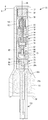
도 2는 도 1의 근접 스위치의 세로 축에 따른 단면도이며; 그리고
도 3은 선택적 플럭스 슬리브와 선택적 대안의 단부 밀봉의 포함을 도시하는 근접 스위치의 세로 축에 따른 단면도이다.
Claims (22)
- 근접 스위치에 있어서:
블라인드 보어, 폐쇄 단부, 및 개방 단부를 갖는 몸체 튜브와;
상기 블라인드 보어 내부에 배치된 자기 근접 스위치 어셈블리와;
상기 자기 근접 스위치 어셈블리와 상기 개방 단부 사이의 상기 블라인드 보어를 덮는 기밀 밀봉과;
상기 기밀 밀봉과 상기 개방 단부 사이의 상기 블라인드 보어의 표면에서 규정된 환형 숄더에 대치하여 배치된 크러쉬 링(crush ring)과;
상기 블라인드 보어의 상기 개방 단부로 돌려끼워서 상기 크러쉬 링을 밀봉하도록 맞물리는 나사식 플러그 몸체를 갖는 크러쉬 링 압축 디바이스와;
상기 크러쉬 링 압축 디바이스와 상기 기밀 밀봉 사이의 임의의 공간을 채우는 포팅을 포함하며;
상기 기밀 밀봉, 상기 포팅, 및 상기 크러쉬 링 압축 디바이스는 가압 및 잠수 테스트동안 상기 블라인드 보어를 밀봉하고 상기 자기 근접 스위치를 보호하는, 근접 스위치. - 청구항 1에 있어서, 상기 크러쉬 링 압축 디바이스는 상기 포팅과 상기 크러쉬 링을 압축하는, 근접 스위치.
- 청구항 1 내지 청구항 2 중 어느 한 항에 있어서, 상기 크러쉬 링은 원형 세로 축을 갖는 중공 튜브를 포함하는, 근접 스위치.
- 청구항 1 내지 3 중 어느 한 항에 있어서, 전기 케이블이 상기 자기 근접 스위치 어셈블리와 전기적으로 연결되고, 상기 크러쉬 링 압축 디바이스는 중심 보어를 가지며, 상기 전기 케이블은 상기 크러쉬 링 압축 디바이스의 상기 중심 보어를 통해 상기 기밀 밀봉으로부터 확장하는, 근접 스위치.
- 청구항 1 내지 4 중 어느 한 항에 있어서, 상기 중심 보어에 상기 전기 케이블을 고정시키도록 배열된 페룰을 더 포함하는, 근접 스위치.
- 청구항 1 내지 5 중 어느 한 항에 있어서, 상기 중심 보어로 상기 페룰을 고정시키도록 배열된 잼 너트를 더 포함하는, 근접 스위치.
- 청구항 1 내지 6 중 어느 한 항에 있어서, 상기 기밀 밀봉은 상기 블라인드 보어와 상보적인 크기와 모양의 디스크와, 상기 디스크를 통해확장하는 튜브를 포함하며, 상기 튜브는 상기 자기 근접 스위치에 인접한 제 1 단부를 가져 그 안에 전기 접촉을 수용하고, 상기 디스크의 외부 환형 주변은 상기 블라인드 보어의 내부 표면으로 밀봉되는, 근접 스위치.
- 청구항 1 내지 7 중 어느 한 항에 있어서, 상기 전기 케이블은 상기 튜브와 전기적으로 결합되는, 근접 스위치.
- 청구항 1 내지 8 중 어느 한 항에 있어서, 상기 디스크를 통해 확장하는 제 2 튜브를 더 포함하며, 상기 제 2 튜브는 그 안에 제 2 전기 접촉을 수용하는, 근접 스위치.
- 청구항 1 내지 9 중 어느 한 항에 있어서, 상기 중심 보어는 원통형 부분과 상기 원통형 부분으로부터 상기 크러쉬 링에 대치하여 맞물려진 상기 플러그 몸체의 제 1단부로 확장하는 제 1 테이퍼링된 부분을 포함하고, 상기 크러쉬 링 압축 디바이스는 상기 포팅을 상기 중심 보어로 압축하는, 근접 스위치.
- 청구항 5 내지 10 중 어느 한 항에 있어서, 상기 중심 보어는 제 2 테이퍼링된 부분을 포함하고, 상기 페룰은 상기 제 2 테이퍼링된 부분으로 끼워 넣어지는, 근접 스위치.
- 근접 스위치에 있어서:
개방 단부를 갖는 제 1 보어를 갖는 몸체 튜브와;
상기 보어 내부에 배치된 근접 스위치 어셈블리와;
상기 개방 단부의 내부에 딱 맞아서 상기 보어의 환형 벽에 대해 고정되는 몸체를 갖는 플러그로서, 상기 몸체는 그를 통과하는 제 2 보어를 갖는, 상기 플러그와;
상기 근접 스위치 어셈블리와 전기적으로 결합되고 상기 제 2 보어를 통해 연장하는 전기 리드와;
상기 전기 리드를 둘러싸며 상기 제 2 보어의 내부에 배치된 페룰과;
상기 플러그와 결합되어 상기 페룰을 상기 제 2 보어와 밀봉 접촉으로 압박하고 상기 제 2 보어 내의 고정 위치에 상기 전기 리드를 고정시키는 잼 너트를 포함하는, 근접 스위치. - 청구항 12에 있어서, 상기 페룰은 상기 제 2 보어 내에 끼워지는 테이퍼링된 노즈를 갖는, 근접 스위치.
- 청구항 1 내지 13 중 어느 한 항에 있어서, 상기 플러그는 상기 근접 스위치 어셈블리에 대치하는 축을 따라 상기 플러그 몸체의 외부 단부로부터 확장하는 니플을 포함하며, 상기 제 2 보어는 상기 니플을 통해 확장하는 테이퍼링된 부분을 갖고, 상기 페룰은 상기 잼 너트에 의해 상기 테이퍼링된 부분으로 끼워지는, 근접 스위치.
- 청구항 1 내지 14 중 어느 한 항에 있어서, 상기 니플은 외부 쓰레드들을 가지며, 상기 잼 너트는 상기 외부의 쓰레드들 상으로 돌려 끼워지는, 근접 스위치.
- 청구항 1 내지 15 중 어느 한 항에 있어서, 상기 테이퍼링된 부분은 원뿔 보어를 형성하는, 근접 스위치.
- 청구항 1 내지 16 중 어느 한 항에 있어서, 상기 페룰은 폴리에테르에테르케톤을 포함하는, 근접 스위치.
- 청구항 1 내지 17 중 어느 한 항에 있어서, 상기 페룰은 상기 제 2 보어와 상기 전기 리드를밀봉되도록 맞물리고 따라서 상기 제 2 보어의 상기 전기 리드 주위에 밀봉을 형성하는, 근접 스위치.
- 청구항 1 내지 18 중 어느 한 항에 있어서, 상기 잼 너트는 상기 페룰과 맞물리는 제 1 내향 방사 플랜지를 포함하며, 선택적으로, 상기 플러그와 맞물리는 쓰레드들을 포함하는 제 2 내향 방사 플랜지를 포함하는, 근접 스위치.
- 근접 스위치 어셈블리에 있어서:
1차 자석과;
상기 1차 자석으로부터 이격된 피스톤 헤드와 상기 피스톤 헤드와 상기 1차 자석을 연결하는 피스톤 로드를 포함하는 플런저와;
상기 피스톤 헤드에 의해 이송되어 상기 피스톤 헤드의 움직임으로 전기 회로를 개방 및/또는 폐쇄하도록 배열된 전기 접촉과;
상기 1차 스위치와 상기 피스톤 헤드 사이의 상기 피스톤 로드에 인접하게 위치된 바이어싱 자석을 포함하며;
상기 바이어싱 자석은 상기 바이어싱 자석을 향하여 또는 그로부터 멀리 상기 피스톤 로드를 따라 축 방향으로 상기 1차 자석을 바이어스하도록 배열되고, 상기 플런저와 상기 1차 자석은 상기 바이어싱 자석에 대하여 축을 따라 이동하도록 배열되며, 상기 1 차 자석과 상기 바이어싱 자석 사이에는 플럭스 슬리브가 배치되지 않는, 근접 스위치 어셈블리. - 청구항 20에 있어서, 상기 1차 자석은 상기 피스톤 로드에 부착된 리테이너에 의해 이송되며, 상기 바이어싱 자석은 상기 바이어싱 자석과 상기 리테이너 사이에 배치된 벽을 포함하는 리테이너 몸체 내로 이송되고, 상기 벽과 상기 리테이너 사이에는 스페이서가 배치되지 않는, 근접 스위치.
- 청구항 1 내지 21 중 어느 한 항에 있어서, 상기 1차 자석은 상기 피스톤 로드에 부착된 리테이너에 의해 이송되며, 상기 바이어싱 자석은 상기 바이어싱 자석과 상기 리테이너 사이에 배치된 벽을 포함하는 리테이너 몸체 내로 이송되고, 상기 벽과 상기 리테이너 사이에는 철계 물질이 배치되지 않는, 근접 스위치.
Applications Claiming Priority (3)
| Application Number | Priority Date | Filing Date | Title |
|---|---|---|---|
| US201161580833P | 2011-12-28 | 2011-12-28 | |
| US61/580,833 | 2011-12-28 | ||
| PCT/US2012/070798 WO2013101628A1 (en) | 2011-12-28 | 2012-12-20 | Proximity switch |
Publications (2)
| Publication Number | Publication Date |
|---|---|
| KR20140119002A true KR20140119002A (ko) | 2014-10-08 |
| KR102049128B1 KR102049128B1 (ko) | 2019-11-26 |
Family
ID=47604104
Family Applications (1)
| Application Number | Title | Priority Date | Filing Date |
|---|---|---|---|
| KR1020147017750A Active KR102049128B1 (ko) | 2011-12-28 | 2012-12-20 | 근접 스위치 |
Country Status (11)
| Country | Link |
|---|---|
| US (1) | US8766751B2 (ko) |
| EP (2) | EP2905798B1 (ko) |
| JP (1) | JP2015506555A (ko) |
| KR (1) | KR102049128B1 (ko) |
| CN (2) | CN103187203B (ko) |
| AR (1) | AR089436A1 (ko) |
| BR (1) | BR112014015829A8 (ko) |
| CA (1) | CA2859538A1 (ko) |
| MX (1) | MX2014008012A (ko) |
| RU (1) | RU2014130181A (ko) |
| WO (1) | WO2013101628A1 (ko) |
Families Citing this family (14)
| Publication number | Priority date | Publication date | Assignee | Title |
|---|---|---|---|---|
| CN103187203B (zh) * | 2011-12-28 | 2017-12-08 | 通用设备和制造公司 | 接近开关 |
| CN103295836B (zh) | 2011-12-28 | 2017-10-31 | 通用设备和制造公司 | 双极‑双掷接近开关 |
| CN104344065B (zh) * | 2013-08-01 | 2019-07-23 | 通用设备和制造公司 | 一种可配置的开关仿真器模块 |
| US10298229B2 (en) | 2017-01-05 | 2019-05-21 | General Equipment And Manufacturing Company, Inc. | Switch adapter |
| US10935151B2 (en) * | 2017-08-29 | 2021-03-02 | Tlx Technologies, Llc. | Solenoid actuator with firing pin position detection |
| DE102018121850B4 (de) | 2018-09-07 | 2020-08-20 | Kraussmaffei Technologies Gmbh | Sensoranordnung mit einer Steckerschutzvorrichtung |
| CN111785541B (zh) * | 2019-04-03 | 2022-08-30 | 上海汽车集团股份有限公司 | 一种用于控制动力电池回路通断的开关 |
| DE102019112581B4 (de) * | 2019-05-14 | 2020-12-17 | Marcel P. HOFSAESS | Temperaturabhängiger Schalter |
| US11456134B2 (en) | 2020-01-09 | 2022-09-27 | General Equipment And Manufacturing Company, Inc. | Magnetic reed switch assembly and method |
| GB2593575B (en) * | 2020-01-24 | 2022-12-14 | General Equipment And Mfg Company Inc D/B/A Topworx Inc | High temperature switch apparatus |
| CN111555747B (zh) * | 2020-04-07 | 2024-12-20 | 武汉船用机械有限责任公司 | 接近开关 |
| GB2588568B (en) | 2021-02-09 | 2021-11-03 | Longvale Ltd | Sensor assemblies |
| WO2022171975A1 (en) * | 2021-02-09 | 2022-08-18 | Longvale Ltd | Sensor assemblies |
| WO2025002354A1 (zh) * | 2023-06-30 | 2025-01-02 | 颂锐机电科技(上海)有限公司 | 一种带永磁机构的密封型无源接近开关 |
Citations (1)
| Publication number | Priority date | Publication date | Assignee | Title |
|---|---|---|---|---|
| US6299426B1 (en) * | 1999-06-25 | 2001-10-09 | Pfa Incorporated | Mold and die casting apparatus including a compact core position sensor unit having magnetic switches |
Family Cites Families (17)
| Publication number | Priority date | Publication date | Assignee | Title |
|---|---|---|---|---|
| US3219811A (en) | 1963-02-05 | 1965-11-23 | Clyde S Young | Watertight flashlight with magnetic switch |
| GB1217677A (en) | 1967-02-17 | 1970-12-31 | Btr Industries Ltd | A pressure indicating device |
| US4117431A (en) * | 1977-06-13 | 1978-09-26 | General Equipment & Manufacturing Co., Inc. | Magnetic proximity device |
| JPS57143624U (ko) * | 1981-03-05 | 1982-09-09 | ||
| GB8715089D0 (en) * | 1987-06-26 | 1987-08-05 | Birns Uk Ltd | Electrical switches |
| US4788517A (en) | 1987-10-08 | 1988-11-29 | Beta Mfg. Co. | Sealed proximity switch assembly |
| US4837539A (en) * | 1987-12-08 | 1989-06-06 | Cameron Iron Works Usa, Inc. | Magnetic sensing proximity detector |
| US5808255A (en) * | 1996-07-22 | 1998-09-15 | Texas Instruments Incorporated | Fluid pressure responsive electric switch |
| US5798910A (en) * | 1996-08-29 | 1998-08-25 | Caloritech Inc. | Sealable housing for electrical components |
| US6127910A (en) * | 1998-06-05 | 2000-10-03 | Topworx, Inc. | Hermetically sealed proximity switch |
| DE10104083C2 (de) * | 2000-01-28 | 2002-07-11 | Ifm Electronic Gmbh | Baueinheit aus einem Näherungsschalter und einem Kabelanschlußteil und Verfahren zu deren Herstellung |
| US6857902B2 (en) * | 2001-02-21 | 2005-02-22 | I F M Electronics Gmbh | Proximity switch and a cable terminal part unit and a process for its manufacture |
| DE10237904B4 (de) * | 2002-06-14 | 2007-05-31 | Ifm Electronic Gmbh | Elektronischer Sensor und Baueinheit aus einem elektronischen Sensor und einem Befestigungselement |
| US7489217B2 (en) * | 2007-04-24 | 2009-02-10 | Rohrig Iii Vincent W | Magnetic proximity sensor |
| WO2009003016A1 (en) * | 2007-06-26 | 2008-12-31 | Swagelok Company | Conduit connection with sensing function |
| CA2801181C (en) * | 2010-06-11 | 2018-05-01 | General Equipment And Manufacturing Company, Inc., D/B/A Topworx, Inc. | Magnetically-triggered proximity switch |
| CN103187203B (zh) * | 2011-12-28 | 2017-12-08 | 通用设备和制造公司 | 接近开关 |
-
2012
- 2012-12-19 CN CN201210599041.8A patent/CN103187203B/zh active Active
- 2012-12-19 CN CN2012207570267U patent/CN203312156U/zh not_active Withdrawn - After Issue
- 2012-12-20 JP JP2014550365A patent/JP2015506555A/ja active Pending
- 2012-12-20 CA CA2859538A patent/CA2859538A1/en not_active Abandoned
- 2012-12-20 WO PCT/US2012/070798 patent/WO2013101628A1/en not_active Ceased
- 2012-12-20 BR BR112014015829A patent/BR112014015829A8/pt not_active IP Right Cessation
- 2012-12-20 EP EP15156180.0A patent/EP2905798B1/en active Active
- 2012-12-20 MX MX2014008012A patent/MX2014008012A/es active IP Right Grant
- 2012-12-20 RU RU2014130181A patent/RU2014130181A/ru not_active Application Discontinuation
- 2012-12-20 EP EP12818730.9A patent/EP2798652B1/en active Active
- 2012-12-20 KR KR1020147017750A patent/KR102049128B1/ko active Active
- 2012-12-21 AR ARP120104945A patent/AR089436A1/es unknown
- 2012-12-27 US US13/728,398 patent/US8766751B2/en active Active
Patent Citations (1)
| Publication number | Priority date | Publication date | Assignee | Title |
|---|---|---|---|---|
| US6299426B1 (en) * | 1999-06-25 | 2001-10-09 | Pfa Incorporated | Mold and die casting apparatus including a compact core position sensor unit having magnetic switches |
Also Published As
| Publication number | Publication date |
|---|---|
| EP2905798B1 (en) | 2016-09-21 |
| JP2015506555A (ja) | 2015-03-02 |
| EP2798652B1 (en) | 2016-04-13 |
| AR089436A1 (es) | 2014-08-20 |
| US20130169388A1 (en) | 2013-07-04 |
| KR102049128B1 (ko) | 2019-11-26 |
| BR112014015829A8 (pt) | 2017-07-04 |
| WO2013101628A1 (en) | 2013-07-04 |
| CN203312156U (zh) | 2013-11-27 |
| MX2014008012A (es) | 2014-08-21 |
| US8766751B2 (en) | 2014-07-01 |
| CN103187203A (zh) | 2013-07-03 |
| EP2905798A1 (en) | 2015-08-12 |
| BR112014015829A2 (pt) | 2017-06-13 |
| CN103187203B (zh) | 2017-12-08 |
| CA2859538A1 (en) | 2013-07-04 |
| EP2798652A1 (en) | 2014-11-05 |
| RU2014130181A (ru) | 2016-02-20 |
Similar Documents
| Publication | Publication Date | Title |
|---|---|---|
| KR102049128B1 (ko) | 근접 스위치 | |
| US9368302B2 (en) | Double pole-double throw proximity switch | |
| US8816197B2 (en) | Pressure balanced connector termination | |
| US7855551B2 (en) | Stick position sensor with removable cover for a sensor head | |
| KR101809216B1 (ko) | 신속 연결분리 커넥터 조립체 | |
| US10003333B2 (en) | Method of manufacturing an enclosed proximity switch assembly | |
| RU2460006C1 (ru) | Сигнализатор стружки | |
| GB2588568A (en) | Sensor assemblies | |
| US6717079B2 (en) | Electrical switches and methods of establishing an electrical connection | |
| US11174976B2 (en) | Magnetic patch system | |
| CN107990039B (zh) | 电磁阀先导装置及具有它的本安隔爆电磁阀 | |
| CA2899978A1 (en) | Quick disconnect connector assembly | |
| RU2381583C1 (ru) | Электромагнит для работы в изделии в условиях повышенного давления окружающей среды | |
| WO2022171975A1 (en) | Sensor assemblies | |
| JPWO2020045327A1 (ja) | ストロークセンサ |
Legal Events
| Date | Code | Title | Description |
|---|---|---|---|
| PA0105 | International application |
Patent event date: 20140626 Patent event code: PA01051R01D Comment text: International Patent Application |
|
| PG1501 | Laying open of application | ||
| A201 | Request for examination | ||
| PA0201 | Request for examination |
Patent event code: PA02012R01D Patent event date: 20171220 Comment text: Request for Examination of Application |
|
| E902 | Notification of reason for refusal | ||
| PE0902 | Notice of grounds for rejection |
Comment text: Notification of reason for refusal Patent event date: 20190111 Patent event code: PE09021S01D |
|
| E701 | Decision to grant or registration of patent right | ||
| PE0701 | Decision of registration |
Patent event code: PE07011S01D Comment text: Decision to Grant Registration Patent event date: 20190820 |
|
| GRNT | Written decision to grant | ||
| PR0701 | Registration of establishment |
Comment text: Registration of Establishment Patent event date: 20191120 Patent event code: PR07011E01D |
|
| PR1002 | Payment of registration fee |
Payment date: 20191120 End annual number: 3 Start annual number: 1 |
|
| PG1601 | Publication of registration | ||
| PR1001 | Payment of annual fee |
Payment date: 20221025 Start annual number: 4 End annual number: 4 |
|
| PR1001 | Payment of annual fee |
Payment date: 20231023 Start annual number: 5 End annual number: 5 |
|
| PR1001 | Payment of annual fee |
Payment date: 20241029 Start annual number: 6 End annual number: 6 |