KR20150100007A - Secondary barrier installation structure and method - Google Patents
Secondary barrier installation structure and method Download PDFInfo
- Publication number
- KR20150100007A KR20150100007A KR1020140021265A KR20140021265A KR20150100007A KR 20150100007 A KR20150100007 A KR 20150100007A KR 1020140021265 A KR1020140021265 A KR 1020140021265A KR 20140021265 A KR20140021265 A KR 20140021265A KR 20150100007 A KR20150100007 A KR 20150100007A
- Authority
- KR
- South Korea
- Prior art keywords
- insulation panel
- barrier
- panel
- heat insulating
- panels
- Prior art date
- Legal status (The legal status is an assumption and is not a legal conclusion. Google has not performed a legal analysis and makes no representation as to the accuracy of the status listed.)
- Ceased
Links
- 230000004888 barrier function Effects 0.000 title claims abstract description 91
- 238000000034 method Methods 0.000 title claims abstract description 25
- 238000009434 installation Methods 0.000 title claims description 29
- 238000009413 insulation Methods 0.000 claims abstract description 126
- 239000012212 insulator Substances 0.000 claims abstract description 13
- 238000003466 welding Methods 0.000 claims abstract description 12
- 239000012774 insulation material Substances 0.000 claims abstract description 6
- 238000003780 insertion Methods 0.000 claims description 21
- 230000037431 insertion Effects 0.000 claims description 21
- 239000010935 stainless steel Substances 0.000 claims description 12
- 229910001220 stainless steel Inorganic materials 0.000 claims description 12
- 239000011810 insulating material Substances 0.000 abstract description 8
- 239000003949 liquefied natural gas Substances 0.000 description 25
- 238000003860 storage Methods 0.000 description 14
- VNWKTOKETHGBQD-UHFFFAOYSA-N methane Chemical compound C VNWKTOKETHGBQD-UHFFFAOYSA-N 0.000 description 10
- 239000000463 material Substances 0.000 description 8
- 238000007789 sealing Methods 0.000 description 8
- 239000003345 natural gas Substances 0.000 description 4
- 229910001374 Invar Inorganic materials 0.000 description 3
- PXHVJJICTQNCMI-UHFFFAOYSA-N Nickel Chemical compound [Ni] PXHVJJICTQNCMI-UHFFFAOYSA-N 0.000 description 3
- 239000012530 fluid Substances 0.000 description 3
- 238000004519 manufacturing process Methods 0.000 description 3
- 239000012528 membrane Substances 0.000 description 3
- ATUOYWHBWRKTHZ-UHFFFAOYSA-N Propane Chemical compound CCC ATUOYWHBWRKTHZ-UHFFFAOYSA-N 0.000 description 2
- 229910000831 Steel Inorganic materials 0.000 description 2
- 239000000853 adhesive Substances 0.000 description 2
- 230000001070 adhesive effect Effects 0.000 description 2
- XAGFODPZIPBFFR-UHFFFAOYSA-N aluminium Chemical compound [Al] XAGFODPZIPBFFR-UHFFFAOYSA-N 0.000 description 2
- 229910052782 aluminium Inorganic materials 0.000 description 2
- 238000007796 conventional method Methods 0.000 description 2
- 230000010354 integration Effects 0.000 description 2
- 229910052759 nickel Inorganic materials 0.000 description 2
- 239000011120 plywood Substances 0.000 description 2
- 125000006850 spacer group Chemical group 0.000 description 2
- 239000010959 steel Substances 0.000 description 2
- 229910000838 Al alloy Inorganic materials 0.000 description 1
- OTMSDBZUPAUEDD-UHFFFAOYSA-N Ethane Chemical compound CC OTMSDBZUPAUEDD-UHFFFAOYSA-N 0.000 description 1
- 229910045601 alloy Inorganic materials 0.000 description 1
- 239000000956 alloy Substances 0.000 description 1
- 238000009835 boiling Methods 0.000 description 1
- 238000001816 cooling Methods 0.000 description 1
- 239000011888 foil Substances 0.000 description 1
- 239000002803 fossil fuel Substances 0.000 description 1
- 239000007789 gas Substances 0.000 description 1
- 239000003365 glass fiber Substances 0.000 description 1
- 238000010030 laminating Methods 0.000 description 1
- 239000007788 liquid Substances 0.000 description 1
- 238000012986 modification Methods 0.000 description 1
- 230000004048 modification Effects 0.000 description 1
- 230000035515 penetration Effects 0.000 description 1
- 235000019362 perlite Nutrition 0.000 description 1
- 239000010451 perlite Substances 0.000 description 1
- 239000004814 polyurethane Substances 0.000 description 1
- 229920002635 polyurethane Polymers 0.000 description 1
- 239000001294 propane Substances 0.000 description 1
- 230000002787 reinforcement Effects 0.000 description 1
- 229920003002 synthetic resin Polymers 0.000 description 1
- 239000000057 synthetic resin Substances 0.000 description 1
- 230000008646 thermal stress Effects 0.000 description 1
- 239000002023 wood Substances 0.000 description 1
- 230000037303 wrinkles Effects 0.000 description 1
Images




Classifications
-
- B—PERFORMING OPERATIONS; TRANSPORTING
- B63—SHIPS OR OTHER WATERBORNE VESSELS; RELATED EQUIPMENT
- B63B—SHIPS OR OTHER WATERBORNE VESSELS; EQUIPMENT FOR SHIPPING
- B63B25/00—Load-accommodating arrangements, e.g. stowing, trimming; Vessels characterised thereby
- B63B25/02—Load-accommodating arrangements, e.g. stowing, trimming; Vessels characterised thereby for bulk goods
- B63B25/08—Load-accommodating arrangements, e.g. stowing, trimming; Vessels characterised thereby for bulk goods fluid
- B63B25/12—Load-accommodating arrangements, e.g. stowing, trimming; Vessels characterised thereby for bulk goods fluid closed
- B63B25/16—Load-accommodating arrangements, e.g. stowing, trimming; Vessels characterised thereby for bulk goods fluid closed heat-insulated
-
- B—PERFORMING OPERATIONS; TRANSPORTING
- B65—CONVEYING; PACKING; STORING; HANDLING THIN OR FILAMENTARY MATERIAL
- B65D—CONTAINERS FOR STORAGE OR TRANSPORT OF ARTICLES OR MATERIALS, e.g. BAGS, BARRELS, BOTTLES, BOXES, CANS, CARTONS, CRATES, DRUMS, JARS, TANKS, HOPPERS, FORWARDING CONTAINERS; ACCESSORIES, CLOSURES, OR FITTINGS THEREFOR; PACKAGING ELEMENTS; PACKAGES
- B65D90/00—Component parts, details or accessories for large containers
- B65D90/02—Wall construction
- B65D90/06—Coverings, e.g. for insulating purposes
-
- F—MECHANICAL ENGINEERING; LIGHTING; HEATING; WEAPONS; BLASTING
- F17—STORING OR DISTRIBUTING GASES OR LIQUIDS
- F17C—VESSELS FOR CONTAINING OR STORING COMPRESSED, LIQUEFIED OR SOLIDIFIED GASES; FIXED-CAPACITY GAS-HOLDERS; FILLING VESSELS WITH, OR DISCHARGING FROM VESSELS, COMPRESSED, LIQUEFIED, OR SOLIDIFIED GASES
- F17C3/00—Vessels not under pressure
- F17C3/02—Vessels not under pressure with provision for thermal insulation
- F17C3/04—Vessels not under pressure with provision for thermal insulation by insulating layers
Landscapes
- Engineering & Computer Science (AREA)
- Mechanical Engineering (AREA)
- Chemical & Material Sciences (AREA)
- Combustion & Propulsion (AREA)
- Ocean & Marine Engineering (AREA)
- Physics & Mathematics (AREA)
- Thermal Sciences (AREA)
- General Engineering & Computer Science (AREA)
- Filling Or Discharging Of Gas Storage Vessels (AREA)
Abstract
본 발명은 2차 방벽 설치 구조 및 방법에 관한 것으로서, 더욱 구체적으로는 2차 단열패널의 갭에 삽입단열재를 설치하는 것이 용이해지고, 2차 단열패널 상에 설치되는 2차 방벽의 일체화를 위한 용접라인을 최소화할 수 있으며, 이로 인해 2차 방벽의 설치에 소요되는 시간과 노력을 줄여서 경제성을 확보할 수 있는 2차 방벽 설치 구조 및 방법에 관한 것이다.
본 발명은 선체의 내측면에 다수로 설치되는 2차 단열패널; 상기 2차 단열패널 사이의 갭에 설치되는 삽입단열재; 상기 삽입단열재 상에 위치하는 코러게이션부와 상기 삽입단열재 양측의 2차 단열패널 상에 각각 설치되는 플랫부가 일체를 이루도록 형성되고, 상기 2차 단열패널 상에 다수로 설치되는 2차 방벽; 및 상기 2차 방벽 간의 경계에 위치하도록 상기 2차 단열패널 상에 설치되는 스트립을 포함하고, 상기 플랫부가 다른 2차 방벽의 플랫부에 용접됨으로써 다수로 연결되는 2차 방벽 설치 구조와 이에 대한 설치 방법을 제공한다.The present invention relates to a structure and a method for installing a secondary barrier, and more specifically, it is easy to install a heat insulating material in a gap of a secondary heat insulating panel, and a weld for welding a secondary barrier provided on the secondary heat insulating panel The present invention relates to a structure and a method for installing a secondary barrier capable of minimizing the time and effort required for installing a secondary barrier, thereby securing economical efficiency.
The present invention relates to a secondary insulation panel, which is installed on a plurality of inner surfaces of a hull; An insulator disposed in a gap between the secondary insulation panels; A secondary barrier formed on the secondary thermal insulation panel so as to be integrally formed with a corrugated portion positioned on the inserted thermal insulation material and a flat portion provided on each of the secondary thermal insulation panels on both sides of the inserted thermal insulation material; And a strip installed on the secondary insulation panel so as to be positioned at a boundary between the secondary walls, wherein the flat part is welded to a flat part of another secondary barrier, ≪ / RTI >
Description
본 발명은 2차 방벽 설치 구조 및 방법에 관한 것으로서, 더욱 구체적으로는 2차 단열패널의 갭에 삽입단열재를 설치하는 것이 용이하도록 하면서, 2차 방벽의 일체화를 위한 용접라인을 최소화하도록 구성된 2차 방벽 설치 구조 및 방법에 관한 것이다.The present invention relates to a secondary barrier installation structure and method, and more particularly, to a secondary barrier installation structure and a secondary barrier installation structure, And a barrier installation structure and method.
천연가스(natural gas)는 메탄(methane)을 주성분으로 하고, 소량의 에탄(ethane), 프로판(propane) 등을 포함하는 화석연료로서, 최근 다양한 기술 분야에서 저공해 에너지원으로서 각광받고 있다.Natural gas is a fossil fuel containing methane as a main component and a small amount of ethane, propane, and the like, and has recently been regarded as a low-pollution energy source in various technical fields.
천연가스는, 육상 또는 해상의 가스배관을 통해 가스 상태로 운반되거나, 또는 액화된 액화천연가스(LNG)의 상태로 LNG 수송선에 저장된 채 원거리의 소비처로 운반된다. 액화천연가스는 천연가스를 극저온(대략 -163℃)으로 냉각하여 얻어지는 것으로 가스 상태의 천연가스일 때보다 그 부피가 대략 1/600로 줄어들게 되므로 해상을 통한 원거리 운반에 매우 적합하다.Natural gas is transported in a gaseous state through land or sea gas pipelines, or is transported to a remote location where it is stored in an LNG carrier in the form of liquefied natural gas (LNG). Liquefied natural gas is obtained by cooling natural gas at a cryogenic temperature (approximately -163 ° C), and its volume is reduced to approximately 1/600 of that of natural gas in a gaseous state, making it well suited for long distance transportation through the sea.
액화천연가스 운반선, LNG RV, LNG FPSO, LNG FSRU 등의 선박 또는 해상 구조물에는 액화천연가스를 보관 및 저장할 수 있는 화물창(cargo, 저장탱크)이 구비된다. 액화천연가스의 끓는점은 대기압에서 약 -163℃ 정도이므로, 액화천연가스의 화물창은 액화천연가스를 안전하게 보관하고 저장하기 위해 알루미늄강, 스테인리스강, 35% 니켈강 등과 같은 초저온에 견딜 수 있는 재료로 제작될 수 있으며, 열응력 및 열수축에 강인하고, 열침입을 막을 수 있는 구조로 설계된다.LNG RV, LNG FPSO, LNG FSRU, and other marine structures are equipped with cargo (storage tank) that can store and store liquefied natural gas. Since the boiling point of liquefied natural gas is about -163 ° C at atmospheric pressure, the liquefied natural gas hold is made of materials that can withstand extremely low temperatures such as aluminum steel, stainless steel and 35% nickel steel to safely store and store liquefied natural gas And is designed to be resistant to thermal stress and heat shrinkage, and to prevent heat penetration.
이러한 저장탱크는 단열재에 화물의 하중이 직접적으로 작용하는지 여부에 따라 독립탱크형(Independent Tank)과 멤브레인형(Membrane Type)으로 분류되는데, 멤브레인형 저장탱크로는 GTT NO 96형과 TGZ MARK Ⅲ형을 예로 들 수 있고, 독립탱크형 저장탱크는 MOSS형과 IHI-SPB형을 포함한다.These storage tanks are classified into independent tanks and membrane types depending on whether the load of the cargo directly acts on the insulation. The membrane type storage tanks are GTT NO 96 type and TGZ MARK III type And the independent tank type storage tanks include MOSS type and IHI-SPB type.
전술한 NO 96형 및 MARK-Ⅲ형 탱크구조는 미국 특허 제 6,035,795 호, 제 6,378,722 호, 제 5,586,513 호 및 미국 특허공개 제 2003-0000949 호 등과, 대한민국 특허공개 제 10-2000-0011347 호 및 제 10-2000-0011346 호 등에 기재되어 있다. 또한, 독립탱크형 저장탱크의 구조는 대한민국 특허 제 10-15063 호 및 제 10-305513 호 등에 기재되어 있다.The above NO 96 and MARK-III tank structures are described in U.S. Patent Nos. 6,035,795, 6,378,722, 5,586,513, and U.S. Patent Publication No. 2003-0000949, Korean Patent Laid-open Nos. 10-2000-0011347 and 10 -2000-0011346. Further, the structure of the independent tank type storage tank is described in Korean Patent No. 10-15063 and No. 10-305513.
도 1에는 NO 96형의 저장탱크의 단열 구조를 개략적으로 도시하였다. Fig. 1 schematically shows a heat insulating structure of a NO 96 type storage tank.
NO 96형의 저장탱크의 단열 구조는, 0.5 ~ 1.5㎜ 두께의 인바(Invar) 강(36% Ni)으로 이루어지는 1차 밀봉벽(1) 및 2차 밀봉벽(3)과, 플라이우드 박스(plywood box) 및 펄라이트(perlite) 등으로 이루어지는 1차 단열벽(2) 및 2차 단열벽(4)이, 선체의 내부 상에 번갈아 적층 설치되어 이루어진다.The insulating structure of the NO 96 type storage tank is composed of a
이러한 NO 96형의 경우, 1차 밀봉벽(1) 및 2차 밀봉벽(3)이 거의 같은 정도의 액밀성 및 강도를 지님으로써 1차 밀봉벽의 누설시 상당한 기간 동안 2차 밀봉벽만으로도 화물을 안전하게 지탱할 수 있으나, 고가의 인바 강으로 1차 및 2차 밀봉벽이 이루어짐에 따라 제작 비용이 높은 단점이 있다. In the case of the NO 96 type, since the
도 2에는 MARK-Ⅲ형의 저장탱크의 단열 구조를 개략적으로 도시하였다. Fig. 2 schematically shows a heat insulation structure of the MARK-type storage tank.
MARK-Ⅲ형의 저장탱크의 단열 구조는 1차 단열벽(10)과 2차 단열벽(20)을 적층하고, 1차 단열벽 상부에 마련되는 1차 방벽(30)은 스테인리스 강(SUS)으로 이루어지고 1차 단열벽과 2차 단열벽 사이에 마련되는 2차 방벽(40)은 유리 섬유와 알루미늄 포일이 적층 및 접착된 트리플렉스로 이루어진다. 1차 방벽(30)을 이루는 스테인리스 강에는 액화천연가스의 저온에 의한 열수축을 완충하기 위하여 주름 구조(corrugation)을 마련한다. 이러한 MARK-Ⅲ형의 저장탱크의 단열 구조는 주름 구조로 인해 설치 공정이 다소 까다롭고, 2차 방벽에는 단열벽 배치와의 간섭 때문에 주름 구조의 SUS를 적용하기 어려워 트리플렉스를 적용하므로 2중 금속 밀봉벽의 NO 96형보다 안전성이 낮아지는 단점이 있다. The primary insulation wall of the MARK-III type storage tank is formed by laminating the
이와 같은 선박이나 부유식 해상 구조물은 초저온 상태로 액화시킨 LNG를 보관 및 저장할 수 있는 LNG 탱크에 대한 종래 기술로는, 한국공개특허 제10-2012-0134596호의 액화천연가스 화물창의 단열구조가 있다. 이는 선체 내측면에 결합되며, 단열을 행하도록 형성되는 복수개의 인슐레이션 패널부; 상기 복수개의 인슐레이션 패널부 상부와 결합하는 2차 방벽; 상기 2차 방벽 상면에 배치되는 스페이서 합판; 및 상기 복수개의 스페이서 합판 상부와 결합하는 1차 방벽을 포함한다.As a conventional technique for an LNG tank capable of storing and storing LNG that has been liquefied at a cryogenic temperature, there is a heat insulation structure of a liquefied natural gas cargo hold of Korean Patent Laid-Open No. 10-2012-0134596. A plurality of insulation panel parts coupled to the inner surface of the hull and formed to perform thermal insulation; A secondary barrier coupled with an upper portion of the plurality of insulation panel portions; A spacer plywood disposed on the upper surface of the secondary barrier; And a primary barrier coupled with the upper portion of the plurality of spacer pans.
이와 같은 종래 기술에서, 인슐레이션 패널, 즉 2차 단열패널의 경우 설치와 제작 공차 등의 이유로 갭(gap)이 존재하며, 이 부분에 대한 단열이 필요하므로 갭 인슐레이션에 해당하는 삽입단열재가 설치되는데, 2차 방벽의 멤브레인 형상에 따라 설치 방법이 많이 달라진다. In such a conventional technique, an insulation panel corresponding to a gap insulation is installed in an insulation panel, that is, a secondary insulation panel, because there is a gap due to mounting and manufacturing tolerances and insulation is required for the insulation panel. The installation method varies greatly depending on the membrane shape of the secondary barrier.
또한 종래 기술에서 삽입단열재가 설치되기 위하여, 2차 방벽을 분리하지 않고서 전체를 설치하기란 실제 공정에서 많은 어려움이 따르기 때문에 2차 방벽을 분리하여 설치 후, 이들에 대한 용접을 수행할 필요가 있었다. 이때, 플랫부(flat part)와 코러게이션부(corrugation part)로 이루어지는 2차 방벽을 어떤 구조로 분리하여 어떤 방식으로 용접하는지에 따라, 2차 방벽의 설치에 소요되는 시간과 노력이 크게 차이나고, 특히 2차 방벽의 일체화를 위한 용접라인이 많아질수록 비경제적이라는 문제점을 가지고 있었다. 따라서, 2차 단열패널 사이에 갭 인슐레이션에 해당하는 삽입단열재의 설치를 가능하도록 하면서도 2차 방벽의 용접라인을 줄여서 2차 방벽의 경제적인 설치를 가능하도록 하는 방안을 강구할 필요가 있었다.Also, in the prior art, it is necessary to separate and install the secondary barriers and then perform welding for them because it is difficult in the actual process to install the whole without installing the secondary barrier in order to install the insulator . At this time, the time and effort required for the installation of the secondary barrier vary greatly depending on how the secondary barrier composed of a flat part and a corrugation part is separated into a certain structure and how it is welded And particularly, as the number of welding lines for integrating the secondary barrier increases, it is uneconomical. Therefore, it has been necessary to find a way to enable the economical installation of the secondary barrier by reducing the welding line of the secondary barrier while enabling the installation of the insulator corresponding to the gap insulation between the secondary insulation panels.
본 발명은 상기한 바와 같은 종래의 문제점을 해결하기 위한 것으로서, 2차 단열패널의 갭에 삽입단열재를 설치하는 것이 용이하도록 하면서, 2차 방벽의 일체화를 위한 용접라인을 최소화하여 2차 방벽의 설치에 소요되는 시간과 노력을 줄여서 경제성을 확보하도록 하는데 목적이 있다.It is an object of the present invention to solve the above-mentioned problems of the prior art, and it is an object of the present invention to provide a method of installing a heat insulating material in a gap of a secondary thermal insulating panel by minimizing a welding line for integrating a secondary wall, To reduce the time and effort required to ensure the economic efficiency.
상기 목적을 달성하기 위한 본 발명의 일 측면에 따르면, 선체의 내측면에 다수로 설치되는 2차 단열패널; 상기 2차 단열패널 사이의 갭에 설치되는 삽입단열재; 상기 삽입단열재 상에 위치하는 코러게이션부와 상기 삽입단열재 양측의 2차 단열패널 상에 각각 설치되는 플랫부가 일체를 이루도록 형성되고, 상기 2차 단열패널 상에 다수로 설치되는 2차 방벽; 및 상기 2차 방벽 간의 경계에 위치하도록 상기 2차 단열패널 상에 설치되는 스트립을 포함하고, 상기 플랫부가 다른 2차 방벽의 플랫부에 용접됨으로써 다수로 연결되는 2차 방벽 설치 구조가 제공된다.According to an aspect of the present invention, there is provided a secondary insulation panel, An insulator disposed in a gap between the secondary insulation panels; A secondary barrier formed on the secondary thermal insulation panel so as to be integrally formed with a corrugated portion positioned on the inserted thermal insulation material and a flat portion provided on each of the secondary thermal insulation panels on both sides of the inserted thermal insulation material; And a strip installed on the secondary adiabatic panel so as to be positioned at a boundary between the secondary barriers, wherein the flat part is welded to the flat part of the other secondary barrier to provide a plurality of secondary barrier mounting structures.
본 발명의 다른 측면에 따르면, 선체의 내측면에 다수로 설치되는 2차 단열패널; 상기 2차 단열패널 사이의 갭에 위치하도록 상기 2차 단열패널의 측부에 일체로 형성되는 삽입단열부; 상기 삽입단열부 상에 위치하는 코러게이션부와 상기 삽입단열부 양측의 2차 단열패널 상에 각각 설치되는 플랫부가 일체를 이루도록 형성되고, 상기 2차 단열패널 상에 다수로 설치되는 2차 방벽; 및 상기 2차 방벽 간의 경계에 위치하도록 상기 2차 단열패널 상에 설치되는 스트립을 포함하고, 상기 플랫부가 다른 2차 방벽의 플랫부에 용접됨으로써 다수로 연결되는 2차 방벽 설치 구조가 제공된다.According to another aspect of the present invention, there is provided a secondary insulation panel that is installed on a plurality of inner surfaces of a hull; An insertion heat insulating part integrally formed on a side of the secondary heat insulating panel so as to be positioned in a gap between the secondary heat insulating panels; A secondary barrier formed on the secondary thermal insulation panel so as to integrally form a corrugated portion positioned on the insertion heat insulating portion and a flat portion provided on each of the secondary thermal insulating panels on both sides of the inserted thermal insulating portion; And a strip installed on the secondary adiabatic panel so as to be positioned at a boundary between the secondary barriers, wherein the flat part is welded to the flat part of the other secondary barrier to provide a plurality of secondary barrier mounting structures.
상기 2차 방벽은 상기 플랫부가 상기 2차 단열패널의 중심부까지 연장되도록 형성될 수 있다.The secondary barrier may be formed such that the flat portion extends to a central portion of the secondary thermal insulation panel.
상기 스트립은 상기 2차 단열패널에 삽입되어 상기 2차 단열패널과 동일면을 이룰 수 있다.The strip may be inserted into the secondary insulation panel to form the same surface as the secondary insulation panel.
상기 스트립은 상기 2차 단열패널의 중심부에 설치될 수 있다.The strip may be installed at the center of the secondary insulation panel.
상기 스트립은 스테인레스스틸 재질로 이루어질 수 있다.The strip may be made of stainless steel.
본 발명의 또 다른 측면에 따르면, 2차 방벽이 고정되기 위한 스트립이 설치되는 2차 단열패널을 선체의 내측면에 설치하고, 상기 삽입단열부 상에 위치하는 코러게이션부와 상기 삽입단열부 양측의 2차 단열패널 상에 각각 설치되는 플랫부가 일체를 이루는 2차 방벽을 상기 2차 단열패널 상에 다수로 설치하고, 상기 플랫부를 다른 2차 방벽의 플랫부에 용접함으로써 상기 2차 방벽을 다수로 연결하는 단계를 제공한다.According to another aspect of the present invention, there is provided a secondary insulation panel on which a strip for securing a secondary barrier is installed on the inner surface of a hull, and a corrugated portion positioned on the inserted heat insulating portion, A plurality of secondary walls integrally formed with the flat portions provided on the secondary insulation panels of the plurality of secondary walls are installed on the secondary insulation panel and the flat portions are welded to the flat portions of the other secondary walls, Lt; / RTI >
이격 배치된 상기 복수의 2차 단열패널 사이에 삽입단열재가 별도로 설치될 수 있다. And an insulative thermal insulating material may be separately provided between the plurality of secondary insulating panels spaced apart from each other.
상기 2차 단열패널의 측부에 일체로 형성되는 삽입단열부가 구비되어 상기 2차 단열패널 사이의 갭에 위치할 수 있다. And an insertion heat insulating portion integrally formed on a side portion of the secondary heat insulating panel may be disposed in a gap between the secondary heat insulating panels.
상기 스트립은 상기 2차 단열패널에 삽입되어 상기 2차 단열패널과 동일면을 이룰 수 있고, 상기 2차 단열패널의 중심부에 설치될 수 있으며, 스테인레스스틸 재질로 이루어질 수 있다.The strip may be inserted into the secondary insulation panel to form the same surface as the secondary insulation panel, may be installed at the center of the secondary insulation panel, and may be made of stainless steel.
상기 2차 방벽을 다수로 연결하는 단계는 상기 2차 방벽의 플랫부가 상기 2차 단열패널의 중심부까지 연장될 수 있다.The step of connecting the plurality of secondary walls may extend the flat portion of the secondary barrier to the central portion of the secondary insulation panel.
본 발명에 따르면, 2차 단열패널의 갭에 삽입단열재를 설치하는 것이 용이해지고, 2차 단열패널 상에 설치되는 2차 방벽의 일체화를 위한 용접라인을 최소화할 수 있으며, 2차 방벽의 설치에 소요되는 시간과 노력을 줄여서 경제성을 확보할 수 있다.According to the present invention, it is easy to install the insulator in the gap of the secondary insulation panel, the welding line for the integration of the secondary barrier provided on the secondary insulation panel can be minimized, and the installation of the secondary barrier It is possible to secure economical efficiency by reducing the time and effort required.
도 1은 NO 96형의 저장탱크의 단열 구조를 개략적으로 도시한 사시도.
도 2는 MARK-Ⅲ형의 저장탱크의 단열 구조를 개략적으로 도시한 사시도.
도 3 내지 도 6은 본 발명의 제 1 실시례에 따른 2차 방벽 설치 방법을 순차적으로 도시한 단면도.
도 7 내지 도 9는 본 발명의 제 2 실시례에 따른 2차 방벽 설치 방법을 순차적으로 도시한 단면도.1 is a perspective view schematically showing a heat insulating structure of a NO 96 type storage tank;
2 is a perspective view schematically showing a heat insulating structure of a storage tank of a MARK-III type.
3 to 6 are sectional views sequentially showing a second barrier installation method according to the first embodiment of the present invention.
7 to 9 are sectional views sequentially showing a second barrier installation method according to a second embodiment of the present invention.
이하 첨부한 도면을 참조하여 본 발명의 바람직한 실시례에 대한 구성 및 작용을 상세히 설명하면 다음과 같다. 또한 하기 실시례는 여러 가지 다른 형태로 변형될 수 있으며, 본 발명의 범위가 하기 실시례에 한정되는 것은 아니다. DETAILED DESCRIPTION OF THE PREFERRED EMBODIMENTS Hereinafter, preferred embodiments of the present invention will be described in detail with reference to the accompanying drawings. In addition, the following embodiments can be modified into various other forms, and the scope of the present invention is not limited to the following embodiments.
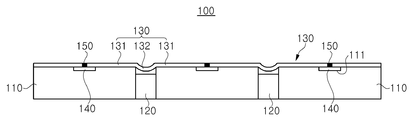
도 6는 본 발명의 제 1 실시례에 따른 2차 방벽 설치 구조를 도시한 단면도이다.6 is a cross-sectional view showing a secondary barrier installation structure according to the first embodiment of the present invention.
도 6에 도시된 바와 같이, 본 발명의 제 1 실시례에 따른 2차 방벽 설치 구조(100)는 LNG, LPG 등과 같은 극저온 유체를 저장하는 탱크의 단열 구조를 이루게 되는데, 2차 단열패널(secondary insulation panel; 110), 삽입단열재(120), 2차 방벽(secondary barrier; 130) 및 스트립(strip; 140)을 포함한다.As shown in FIG. 6, the secondary
2차 단열패널(110)은 선체의 내측면을 따라 다수로 설치될 수 있고, 고정부재나 접착제 등을 이용하여 선체의 내측면에 고정될 수 있으며, 단열을 위하여 목재나 합성수지 또는 폴리우레탄 등의 단열재로 이루어지거나, 이들의 조합으로 이루어지는 블록 내지 플레이트일 수 있으며, 이 밖에도 다양한 단열재료로 제작될 수 있고, 선체 내에 일렬로 배열됨은 물론 2차원적으로 배열될 수 있으며, LNG 탱크의 형상 및 설치 위치에 따라 적절한 형태의 블록 내지 플레이트 구조로 이루어질 수 있다. 여기서 선체는 LNG 탱크를 필요로 하는 LNG 운반선(LNG carrier)의 선체 외에도, LNG RV(LNG Regasification Vessel)의 선체 뿐만 아니라, LNG FPSO(LNG Floating, Production, Storage and Offloading)나 LNG FSRU(LNG Floating Storage and Regasification Unit) 등과 같은 부유식 해상 구조물의 선체를 포함할 수 있다.The
2차 단열패널(110) 상에는 부가적으로 1차 단열패널과 1차 방벽이 순차적으로 적층됨으로써 LNG 등의 극저온 유체를 저장하기 위한 탱크를 구성할 수 있다.A primary insulation panel and a primary barrier are sequentially stacked on the
삽입단열재(120)는 2차 단열패널(110) 사이의 갭(gap)에 설치되고, 이러한 갭 내에 억지 끼움이나 단순 삽입 또는 접착제나 체결부재 등으로 고정될 수 있으며, 2차 단열패널(110)과 동일하거나, 그 밖의 다양한 단열재료로 제작될 수 있다.The insertion
2차 방벽(130)은 예컨대 인바 합금으로 이루어질 수 있고, 그 밖에도 스테인레스스틸이나 알루미늄 합금을 비롯하여 LNG 등과 같은 극저온 유체의 저온 특성에 견디는 재질로 이루어질 수 있으며, 삽입단열재(120) 상에 위치하는 코러게이션부(corrution part; 132)와 삽입단열재(120) 양측의 2차 단열패널(110) 상에 각각 설치되는 플랫부(flat part; 131)가 일체를 이루도록 형성되고, 2차 단열패널(110) 상에 다수로 설치되며, 플랫부(131)가 다른 2차 방벽(130)의 플랫부(131)에 용접됨으로써 다수로 연결된다. 여기서 플랫부(131)는 평면 구조를 가짐으로써 2차 단열패널(110) 상에 밀착되는 구조를 가지고, 코러게이션부(132) 양측에 측방향으로 연장되도록 각각 형성될 수 있다. 또한 코러게이션부(132)는 2차 단열패널(110) 사이의 갭에 위치함으로써 열수축 등을 허용하도록 주름 구조를 가질 수 있다. 또한 2차 방벽(130)은 본 실시례에서처럼 플랫부(131)가 2차 단열패널(110)의 중심부까지 연장되도록 형성될 수 있다.The
스트립(140)은 2차 방벽(130) 간의 경계에 위치하도록 2차 단열패널(110) 상에 설치되고, 예컨대 스테인레스스틸 재질로 이루어질 수 있으며, 이 밖에도 2차 방벽(130)과 동일한 재질로 이루어질 수 있고, 2차 방벽(130)에 대한 용접으로 인한 영향이 2차 단열패널(110)에 미치는 것을 차단하는 역할을 할 수 있으며, 나아가서 2차 방벽(130)을 지지하는 역할도 할 수 있다. 또한 스트립(140)은 2차 방벽(130) 간의 용접에 의해 형성되는 용접부(150)에 의해 2차 방벽(130)에 고정될 수 있으며, 용접 방식에 따라서는 용접부(150)와 분리될 수도 있다.The
스트립(140)은 2차 단열패널(110)에 형성되는 홈부(111)에 삽입됨으로써 상면이 2차 단열패널(110)과 동일면을 이룰 수 있고, 2차 방벽(130) 간의 경계 위치 뿐만 아니라, 그 외에 보강 내지 지지가 필요한 부분에 설치될 수 있다. 또한 스트립(140)은 본 실시례에서처럼 2차 방벽(130)의 플랫부(131)가 2차 단열패널(110)의 중심부까지 연장 형성되는 점을 감안하여 2차 단열패널(110)의 중심부에 설치될 수 있다.The
도 9는 본 발명의 제 2 실시례에 따른 2차 방벽 설치 구조를 도시한 단면도이다.9 is a cross-sectional view showing a secondary barrier installation structure according to a second embodiment of the present invention.
도 9에 도시된 바와 같이, 본 발명의 제 2 실시례에 따른 2차 방벽 설치 구조(200)는 선체의 내측면에 다수로 설치되는 2차 단열패널(210)과, 2차 단열패널(210) 사이의 갭에 위치하도록 2차 단열패널(210)의 측부에 일체로 형성되는 삽입단열부(220)와, 삽입단열부(220) 상에 위치하는 코러게이션부(132)와 삽입단열부(220) 양측의 2차 단열패널(210) 상에 각각 설치되는 플랫부(131)가 일체를 이루도록 형성되고, 2차 단열패널(210) 상에 다수로 설치되는 2차 방벽(230)과, 2차 방벽(230) 간의 경계에 위치하도록 2차 단열패널(210) 상에 설치되는 스트립(240)을 포함하고, 플랫부(231)가 다른 2차 방벽(230)의 플랫부(231)에 용접됨으로써 다수로 연결된다.9, the second
본 발명의 제 2 실시례에 따른 2차 방벽 설치 구조(200)에서, 2차 방벽(230)은 플랫부(231)가 2차 단열패널(210)의 중심부까지 연장되도록 형성될 수 있다. 또한 스트립(240)은 2차 단열패널(210)의 홈부(211)에 삽입되어 2차 단열패널(210)과 동일면을 이룰 수 있고, 2차 단열패널(210)의 중심부에 설치될 수 있으며, 스테인레스스틸 재질로 이루어질 수 있다. 이 밖에도 본 발명의 제 2 실시례에 따른 2차 방벽 설치 구조(200)는 삽입단열부(220)가 제 1 실시례에 따른 2차 방벽 설치 구조(100)와는 달리, 제 2 단열패널(210)과 일체로 형성되는 점을 제외하고 동일하므로 차이점 위주로 설명하기로 한다.In the secondary
삽입단열부(220)는 2차 단열패널(210)의 측부에 인접하는 다른 2차 단열패널(210) 측으로 연장되도록 형성됨으로써 2차 단열패널(210) 사이의 갭에 위치하여 단열을 유지하도록 한다. 한편 삽입단열부(220)는 본 실시례에서 서로 인접하는 2차 단열패널(210) 중 어느 하나에만 형성됨을 나타내나, 이는 하나의 예시일 뿐, 서로 인접하는 2차 단열패널(210) 각각에 형성되어 2차 단열패널(210)의 갭을 차단하도록 위치할 수 있다.The insertion
도 3 내지 도 6은 본 발명의 제 1 실시례에 따른 2차 방벽 설치 방법을 순차적으로 도시한 단면도로서, 본 발명의 제 1 실시례에 따른 2차 방벽 설치 구조(100)를 예로 든 설치 방법을 나타낸다.3 to 6 are sectional views sequentially showing the secondary barrier installation method according to the first embodiment of the present invention. The installation method of the secondary
도 3 및 도 4에 도시된 바와 같이, 선체의 내측면에 2차 단열패널(110)을 다수로 설치하고, 2차 단열패널(110) 상에 설치되는 스트립(140)이 2차 방벽(130; 도 5에 도시)에의 경계에 해당하는 부분에 위치하도록 하며, 2차 단열패널(110) 사이의 갭에 삽입단열재(120)를 설치한다.3 and 4, a plurality of
스트립(140)은 선체에 설치되기 전의 2차 단열패널(110)에 미리 설치되거나, 선체에 설치를 마친 2차 단열패널(110)에 설치될 수 있다. 또한 삽입단열재(120)는 본 실시례에서 스트립(140) 설치 후에 2차 단열패널(110) 사이에 설치됨을 나타내나, 이는 하나의 예시일 뿐, 스트립(140)이 설치되기 전에 2차 단열패널(110) 사이에 설치될 수 있다. 이와 같이 2차 단열패널(110), 스트립(140), 그리고 삽입단열재(120)의 설치 순서는 제조 공정에 따라 달리 정해질 수 있다. 또한 스트립(140)은 2차 단열패널(110)의 홈부(111)에 삽입되어 2차 단열패널(110)과 동일면을 이룰 수 있고, 2차 단열패널(110)의 중심부에 각각 설치될 수 있으며, 스테인레스스틸 재질 또는 2차 방벽(130)과 동일한 재질로 이루어질 수 있다.The
도 5 및 도 6에 도시된 바와 같이, 2차 단열패널(110), 스트립(140), 그리고 삽입단열재(120)의 설치를 마치면, 삽입단열재(120) 상에 위치하는 코러게이션부(132)와 삽입단열재(120) 양측의 2차 단열패널(110) 상에 각각 설치되는 플랫부(131)가 일체를 이루는 2차 방벽(130)을 2차 단열패널(110) 상에 다수로 설치하고, 플랫부(131)를 다른 2차 방벽(130)의 플랫부(131)에 용접함으로써 2차 방벽(130)을 다수로 연결한다. 따라서 2차 방벽(130)의 플랫부(131) 끝단에 용접부(150)가 형성된다. 여기서 2차 방벽(130)의 플랫부(131)는 2차 단열패널(110)의 중심부까지 연장되도록 형성될 수 있다.5 and 6, when the
도 7 내지 도 9은 본 발명의 제 2 실시례에 따른 2차 방벽 설치 방법을 순차적으로 도시한 단면도로서, 본 발명의 제 2 실시례에 따른 2차 방벽 설치 구조(200)를 예로 든 설치 방법을 나타낸다.7 to 9 are sectional views sequentially showing the second barrier installation method according to the second embodiment of the present invention. In the installation method of the second
도 7에 도시된 바와 같이, 선체의 내측면에 2차 단열패널(210)을 다수로 설치함으로써 2차 단열패널(210)의 측부에 일체로 형성되는 삽입단열부(220)가 2차 단열패널(210) 사이의 갭에 위치하도록 하고, 2차 단열패널(210) 상에 설치되는 스트립(240)이 2차 방벽(230)의 경계에 해당하는 부분에 위치하도록 한다. 7, by providing a plurality of secondary
스트립(240)은 선체에 설치되기 전의 2차 단열패널(210)에 미리 설치되거나, 선체에 설치를 마친 2차 단열패널(210)에 설치될 수 있다. 또한 스트립(240)은 2차 단열패널(210)의 홈부(211)에 삽입되어 2차 단열패널(210)과 동일면을 이룰 수 있고, 2차 단열패널(210)의 중심부에 각각 설치될 수 있으며, 스테인레스스틸 재질 또는 2차 방벽(230)과 동일한 재질로 이루어질 수 있다.The
도 8 및 도 9에 도시된 바와 같이, 2차 단열패널(210)과 스트립(240)의 설치를 마치면, 삽입단열재(220) 상에 위치하는 코러게이션부(232)와 삽입단열재(220) 양측의 2차 단열패널(210) 상에 각각 설치되는 플랫부(231)가 일체를 이루는 2차 방벽(230)을 2차 단열패널(210) 상에 다수로 설치하고, 플랫부(231)를 다른 2차 방벽(230)의 플랫부(231)에 용접함으로써 2차 방벽(230)을 다수로 연결한다. 따라서 2차 방벽(230)의 플랫부(231) 끝단에 용접부(250)가 형성된다. 여기서 2차 방벽(230)의 플랫부(231)는 2차 단열패널(210)의 중심부까지 연장되도록 형성될 수 있다.8 and 9, when the
이와 같은 본 발명에 따른 2차 방벽 설치 구조 및 방법에 따르면, 2차 단열패널의 갭에 삽입단열재를 설치하는 것이 용이해지고, 2차 단열패널 상에 설치되는 2차 방벽의 일체화를 위한 용접라인을 최소화할 수 있으며, 이로 인해 2차 방벽의 설치에 소요되는 시간과 노력을 줄여서 경제성을 확보할 수 있다.According to the present invention, it is easy to install the insulator in the gap of the secondary insulation panel and the welding line for the integration of the secondary barrier installed on the secondary insulation panel Thereby reducing the time and effort required for the installation of the secondary barrier, thereby securing economical efficiency.
본 발명은 상기 실시례에 한정되지 않고, 본 발명의 기술적 요지를 벗어나지 아니하는 범위 내에서 다양하게 수정 또는 변형되어 실시될 수 있음은 본 발명이 속하는 기술분야에서 통상의 지식을 가진 자에 있어서 자명한 것이다.It will be apparent to those skilled in the art that various modifications and variations can be made in the present invention without departing from the spirit and scope of the invention. It is.
110 : 2차 단열패널 111 : 홈부
120 : 삽입단열재 130 : 2차 방벽
131 : 플랫부 132 : 코러게이션부
140 : 스트립 150 : 용접부
210 : 2차 단열패널 211 : 홈부
220 : 삽입단열부 230 : 2차 방벽
231 : 플랫부 232 : 코러게이션부
240 : 스트립 250 : 용접부110: secondary insulation panel 111: groove
120: Insertion insulation 130: Secondary barrier
131: flat part 132:
140: strip 150: welded part
210: secondary insulation panel 211: groove
220: insertion insulator 230: secondary barrier
231: flat part 232:
240: Strip 250: Weld
Claims (13)
상기 2차 단열패널 사이의 갭에 설치되는 삽입단열재;
상기 삽입단열재 상에 위치하는 코러게이션부와 상기 삽입단열재 양측의 2차 단열패널 상에 각각 설치되는 플랫부가 일체를 이루도록 형성되고, 상기 2차 단열패널 상에 다수로 설치되는 2차 방벽; 및
상기 2차 방벽 간의 경계에 위치하도록 상기 2차 단열패널 상에 설치되는 스트립을 포함하고,
상기 플랫부가 다른 2차 방벽의 플랫부에 용접됨으로써 다수로 연결되는, 2차 방벽 설치 구조.A plurality of secondary insulation panels installed on the inner surface of the hull;
An insulator disposed in a gap between the secondary insulation panels;
A secondary barrier formed on the secondary thermal insulation panel so as to be integrally formed with a corrugated portion positioned on the inserted thermal insulation material and a flat portion provided on each of the secondary thermal insulation panels on both sides of the inserted thermal insulation material; And
And a strip installed on the secondary insulation panel so as to be positioned at a boundary between the secondary walls,
And the plurality of flat portions are welded to the flat portions of the other secondary walls.
상기 2차 단열패널 사이의 갭에 위치하도록 상기 2차 단열패널의 측부에 일체로 형성되는 삽입단열부;
상기 삽입단열부 상에 위치하는 코러게이션부와 상기 삽입단열부 양측의 2차 단열패널 상에 각각 설치되는 플랫부가 일체를 이루도록 형성되고, 상기 2차 단열패널 상에 다수로 설치되는 2차 방벽; 및
상기 2차 방벽 간의 경계에 위치하도록 상기 2차 단열패널 상에 설치되는 스트립을 포함하고,
상기 플랫부가 다른 2차 방벽의 플랫부에 용접됨으로써 다수로 연결되는, 2차 방벽 설치 구조.A plurality of secondary insulation panels installed on the inner surface of the hull;
An insertion heat insulating part integrally formed on a side of the secondary heat insulating panel so as to be positioned in a gap between the secondary heat insulating panels;
A secondary barrier formed on the secondary thermal insulation panel so as to integrally form a corrugated portion positioned on the insertion heat insulating portion and a flat portion provided on each of the secondary thermal insulating panels on both sides of the inserted thermal insulating portion; And
And a strip installed on the secondary insulation panel so as to be positioned at a boundary between the secondary walls,
And the plurality of flat portions are welded to the flat portions of the other secondary walls.
상기 2차 방벽은,
상기 플랫부가 상기 2차 단열패널의 중심부까지 연장되도록 형성되는, 2차 방벽 설치 구조.The method according to claim 1 or 2,
Wherein the secondary barrier comprises:
Wherein the flat portion is formed to extend to a central portion of the secondary thermal insulation panel.
상기 스트립은,
상기 2차 단열패널에 삽입되어 상기 2차 단열패널과 동일면을 이루는, 2차 방벽 설치 구조.The method according to claim 1 or 2,
Wherein the strip comprises:
And a secondary barrier installation structure inserted into the secondary insulation panel to form the same surface as the secondary insulation panel.
상기 스트립은,
상기 2차 단열패널의 중심부에 설치되는, 2차 방벽 설치 구조.The method according to claim 1 or 2,
Wherein the strip comprises:
And a second barrier installation structure provided at the center of the secondary insulation panel.
상기 스트립은,
스테인레스스틸 재질로 이루어지는, 2차 방벽 설치 구조.The method according to claim 1 or 2,
Wherein the strip comprises:
A secondary barrier installation structure made of stainless steel.
상기 삽입단열부 상에 위치하는 코러게이션부와 상기 삽입단열부 양측의 2차 단열패널 상에 각각 설치되는 플랫부가 일체를 이루는 2차 방벽을 상기 2차 단열패널 상에 다수로 설치하고,
상기 플랫부를 다른 2차 방벽의 플랫부에 용접함으로써 상기 2차 방벽을 다수로 연결하는 단계를 포함하는, 2차 방벽 설치 방법.A secondary insulation panel on which a strip for fixing the secondary barrier is installed is installed on the inner surface of the hull,
A plurality of secondary walls are integrally formed on the secondary thermal insulation panel, and a plurality of corrugation portions positioned on the insertion heat insulating portion and a plurality of flat portions integrally formed on the secondary thermal insulating panels on both sides of the insertion heat insulating portion,
And connecting the plurality of secondary walls by welding the flat portion to a flat portion of another secondary barrier.
이격 배치된 상기 복수의 2차 단열패널 사이에 삽입단열재가 별도로 설치되는, 2차 방벽 설치 방법.The method of claim 7,
Wherein a plurality of secondary insulation panels spaced apart from each other are separately installed between the secondary insulation panels.
상기 2차 단열패널의 측부에 일체로 형성되는 삽입단열부가 구비되어 상기 2차 단열패널 사이의 갭에 위치하도록 하는, 2차 방벽 설치 방법.The method of claim 7,
Wherein the secondary insulation panel is provided with an insertion heat insulating portion integrally formed on a side portion of the secondary thermal insulating panel so as to be positioned in a gap between the secondary thermal insulating panels.
상기 스트립은,
상기 2차 단열패널에 삽입되어 상기 2차 단열패널과 동일면을 이루는, 2차 방벽 설치 방법.The method of claim 7,
Wherein the strip comprises:
Wherein the secondary insulation panel is inserted into the secondary insulation panel to form the same surface as the secondary insulation panel.
상기 스트립은,
상기 2차 단열패널의 중심부에 설치되는, 2차 방벽 설치 방법.The method of claim 7,
Wherein the strip comprises:
Wherein the secondary barrier is installed at the center of the secondary insulation panel.
상기 스트립은,
스테인레스스틸 재질로 이루어지는, 2차 방벽 설치 방법.The method of claim 7,
Wherein the strip comprises:
A method of installing a secondary barrier, made of stainless steel.
상기 2차 방벽을 다수로 연결하는 단계는,
상기 2차 방벽의 플랫부가 상기 2차 단열패널의 중심부까지 연장되는, 2차 방벽 설치 방법.The method of claim 7,
The step of connecting a plurality of secondary barriers comprises:
Wherein a flat portion of the secondary barrier extends to a central portion of the secondary insulation panel.
Priority Applications (1)
| Application Number | Priority Date | Filing Date | Title |
|---|---|---|---|
| KR1020140021265A KR20150100007A (en) | 2014-02-24 | 2014-02-24 | Secondary barrier installation structure and method |
Applications Claiming Priority (1)
| Application Number | Priority Date | Filing Date | Title |
|---|---|---|---|
| KR1020140021265A KR20150100007A (en) | 2014-02-24 | 2014-02-24 | Secondary barrier installation structure and method |
Publications (1)
| Publication Number | Publication Date |
|---|---|
| KR20150100007A true KR20150100007A (en) | 2015-09-02 |
Family
ID=54241802
Family Applications (1)
| Application Number | Title | Priority Date | Filing Date |
|---|---|---|---|
| KR1020140021265A Ceased KR20150100007A (en) | 2014-02-24 | 2014-02-24 | Secondary barrier installation structure and method |
Country Status (1)
| Country | Link |
|---|---|
| KR (1) | KR20150100007A (en) |
Cited By (3)
| Publication number | Priority date | Publication date | Assignee | Title |
|---|---|---|---|---|
| WO2018024982A1 (en) * | 2016-08-02 | 2018-02-08 | Gaztransport Et Technigaz | Impermeable wall structure |
| KR20210040688A (en) * | 2019-10-04 | 2021-04-14 | 대우조선해양 주식회사 | Insulation Box Reinforcement Structure of Liquefied Gas Storage Tank |
| KR20210040687A (en) * | 2019-10-04 | 2021-04-14 | 대우조선해양 주식회사 | Insulation Box Reinforcement Structure of Liquefied Gas Storage Tank |
-
2014
- 2014-02-24 KR KR1020140021265A patent/KR20150100007A/en not_active Ceased
Cited By (6)
| Publication number | Priority date | Publication date | Assignee | Title |
|---|---|---|---|---|
| WO2018024982A1 (en) * | 2016-08-02 | 2018-02-08 | Gaztransport Et Technigaz | Impermeable wall structure |
| FR3054871A1 (en) * | 2016-08-02 | 2018-02-09 | Gaztransport Et Technigaz | SEALED WALL STRUCTURE |
| CN109790958A (en) * | 2016-08-02 | 2019-05-21 | 气体运输技术公司 | Leak-proof wall structure |
| CN109790958B (en) * | 2016-08-02 | 2021-09-07 | 气体运输技术公司 | Leak-proof wall structure |
| KR20210040688A (en) * | 2019-10-04 | 2021-04-14 | 대우조선해양 주식회사 | Insulation Box Reinforcement Structure of Liquefied Gas Storage Tank |
| KR20210040687A (en) * | 2019-10-04 | 2021-04-14 | 대우조선해양 주식회사 | Insulation Box Reinforcement Structure of Liquefied Gas Storage Tank |
Similar Documents
| Publication | Publication Date | Title |
|---|---|---|
| JP6479221B2 (en) | Sealed heat insulation tank having a secondary sealed membrane provided with a corner arrangement with a corrugated metal sheet | |
| KR102048641B1 (en) | Vessels with insulated corner blocks provided with stress relief slots | |
| KR101751838B1 (en) | Insulation structure of liquefied natural gas cargo tank without anchor strip, cargo tank having the structure, and liquefied natural gas carrier | |
| KR102387173B1 (en) | Insulation structure of 90 degree corner in liquefied gas cargo tank, and cargo tank having the insulation structure | |
| KR102535971B1 (en) | Insulation system of membraine type storage tank and membrain type storage tank | |
| US20170158291A1 (en) | Corner panel for ultra-low temperature fluid storage tank, and ultra-low temperature fluid thermal insulation system having same | |
| KR102535974B1 (en) | Heat insulation installation method for cryogenic liquid storage tank | |
| KR20220068318A (en) | Insulation system of liquefied gas storage tank with double metallic barrier structure | |
| KR20150028493A (en) | Insulation Structure For LNG Cargo Tank And Method For Connecting The Same | |
| KR101751839B1 (en) | Insulation system of membraine type storage tank and membrain type storage tank | |
| KR20160004756A (en) | Lng storage tank and insulation pannel securing device thereof | |
| KR20150100007A (en) | Secondary barrier installation structure and method | |
| KR101686507B1 (en) | Lng storage tank | |
| KR20160004754A (en) | Lng storage tank and insulation pannel securing device thereof | |
| KR101814445B1 (en) | Panel fixing device for liquefied gas tank, and liquefied gas tank having the same | |
| KR20150082780A (en) | Insulation Structure For LNG Cargo Tank And Constructing Method Of The Same | |
| KR101567874B1 (en) | Connecting Structure And Method For Insulation System | |
| KR101686506B1 (en) | Lng storage tank and insulation pannel thereof | |
| KR101713852B1 (en) | Secondary barrier installation structure and method | |
| KR101567877B1 (en) | Connecting Structure And Method For Insulation System | |
| KR102525949B1 (en) | Insulation system of membraine type storage tank and membrain type storage tank | |
| EP3733500A1 (en) | Membrane bonding structure and liquefied gas storage tank comprising same | |
| KR102647306B1 (en) | Liquefied gas cargo insulation system and membrane fixing structure thereof | |
| KR20140021198A (en) | Insulation system for membrane type lng cargo tank | |
| KR101751840B1 (en) | Corner insulation wall of membraine type storage tank, membrain type storage tank comprising the same and insulation system of lng storage tank |
Legal Events
| Date | Code | Title | Description |
|---|---|---|---|
| PA0109 | Patent application |
Patent event code: PA01091R01D Comment text: Patent Application Patent event date: 20140224 |
|
| A201 | Request for examination | ||
| PA0201 | Request for examination |
Patent event code: PA02012R01D Patent event date: 20141224 Comment text: Request for Examination of Application Patent event code: PA02011R01I Patent event date: 20140224 Comment text: Patent Application |
|
| PG1501 | Laying open of application | ||
| E902 | Notification of reason for refusal | ||
| PE0902 | Notice of grounds for rejection |
Comment text: Notification of reason for refusal Patent event date: 20160808 Patent event code: PE09021S01D |
|
| E902 | Notification of reason for refusal | ||
| PE0902 | Notice of grounds for rejection |
Comment text: Notification of reason for refusal Patent event date: 20170222 Patent event code: PE09021S01D |
|
| E601 | Decision to refuse application | ||
| PE0601 | Decision on rejection of patent |
Patent event date: 20170426 Comment text: Decision to Refuse Application Patent event code: PE06012S01D Patent event date: 20170222 Comment text: Notification of reason for refusal Patent event code: PE06011S01I Patent event date: 20160808 Comment text: Notification of reason for refusal Patent event code: PE06011S01I |