KR20150141908A - Heat recovery apparatus - Google Patents
Heat recovery apparatus Download PDFInfo
- Publication number
- KR20150141908A KR20150141908A KR1020150081736A KR20150081736A KR20150141908A KR 20150141908 A KR20150141908 A KR 20150141908A KR 1020150081736 A KR1020150081736 A KR 1020150081736A KR 20150081736 A KR20150081736 A KR 20150081736A KR 20150141908 A KR20150141908 A KR 20150141908A
- Authority
- KR
- South Korea
- Prior art keywords
- refrigerant
- compressor
- flowing
- refrigerant flow
- evaporator
- Prior art date
- Legal status (The legal status is an assumption and is not a legal conclusion. Google has not performed a legal analysis and makes no representation as to the accuracy of the status listed.)
- Granted
Links
Images


Classifications
-
- F—MECHANICAL ENGINEERING; LIGHTING; HEATING; WEAPONS; BLASTING
- F25—REFRIGERATION OR COOLING; COMBINED HEATING AND REFRIGERATION SYSTEMS; HEAT PUMP SYSTEMS; MANUFACTURE OR STORAGE OF ICE; LIQUEFACTION SOLIDIFICATION OF GASES
- F25B—REFRIGERATION MACHINES, PLANTS OR SYSTEMS; COMBINED HEATING AND REFRIGERATION SYSTEMS; HEAT PUMP SYSTEMS
- F25B6/00—Compression machines, plants or systems, with several condenser circuits
- F25B6/02—Compression machines, plants or systems, with several condenser circuits arranged in parallel
-
- F—MECHANICAL ENGINEERING; LIGHTING; HEATING; WEAPONS; BLASTING
- F25—REFRIGERATION OR COOLING; COMBINED HEATING AND REFRIGERATION SYSTEMS; HEAT PUMP SYSTEMS; MANUFACTURE OR STORAGE OF ICE; LIQUEFACTION SOLIDIFICATION OF GASES
- F25B—REFRIGERATION MACHINES, PLANTS OR SYSTEMS; COMBINED HEATING AND REFRIGERATION SYSTEMS; HEAT PUMP SYSTEMS
- F25B43/00—Arrangements for separating or purifying gases or liquids; Arrangements for vaporising the residuum of liquid refrigerant, e.g. by heat
-
- F—MECHANICAL ENGINEERING; LIGHTING; HEATING; WEAPONS; BLASTING
- F01—MACHINES OR ENGINES IN GENERAL; ENGINE PLANTS IN GENERAL; STEAM ENGINES
- F01K—STEAM ENGINE PLANTS; STEAM ACCUMULATORS; ENGINE PLANTS NOT OTHERWISE PROVIDED FOR; ENGINES USING SPECIAL WORKING FLUIDS OR CYCLES
- F01K11/00—Plants characterised by the engines being structurally combined with boilers or condensers
- F01K11/02—Plants characterised by the engines being structurally combined with boilers or condensers the engines being turbines
-
- F—MECHANICAL ENGINEERING; LIGHTING; HEATING; WEAPONS; BLASTING
- F01—MACHINES OR ENGINES IN GENERAL; ENGINE PLANTS IN GENERAL; STEAM ENGINES
- F01K—STEAM ENGINE PLANTS; STEAM ACCUMULATORS; ENGINE PLANTS NOT OTHERWISE PROVIDED FOR; ENGINES USING SPECIAL WORKING FLUIDS OR CYCLES
- F01K13/00—General layout or general methods of operation of complete plants
- F01K13/02—Controlling, e.g. stopping or starting
-
- F—MECHANICAL ENGINEERING; LIGHTING; HEATING; WEAPONS; BLASTING
- F01—MACHINES OR ENGINES IN GENERAL; ENGINE PLANTS IN GENERAL; STEAM ENGINES
- F01K—STEAM ENGINE PLANTS; STEAM ACCUMULATORS; ENGINE PLANTS NOT OTHERWISE PROVIDED FOR; ENGINES USING SPECIAL WORKING FLUIDS OR CYCLES
- F01K25/00—Plants or engines characterised by use of special working fluids, not otherwise provided for; Plants operating in closed cycles and not otherwise provided for
- F01K25/08—Plants or engines characterised by use of special working fluids, not otherwise provided for; Plants operating in closed cycles and not otherwise provided for using special vapours
-
- F—MECHANICAL ENGINEERING; LIGHTING; HEATING; WEAPONS; BLASTING
- F01—MACHINES OR ENGINES IN GENERAL; ENGINE PLANTS IN GENERAL; STEAM ENGINES
- F01K—STEAM ENGINE PLANTS; STEAM ACCUMULATORS; ENGINE PLANTS NOT OTHERWISE PROVIDED FOR; ENGINES USING SPECIAL WORKING FLUIDS OR CYCLES
- F01K7/00—Steam engine plants characterised by the use of specific types of engine; Plants or engines characterised by their use of special steam systems, cycles or processes; Control means specially adapted for such systems, cycles or processes; Use of withdrawn or exhaust steam for feed-water heating
- F01K7/16—Steam engine plants characterised by the use of specific types of engine; Plants or engines characterised by their use of special steam systems, cycles or processes; Control means specially adapted for such systems, cycles or processes; Use of withdrawn or exhaust steam for feed-water heating the engines being only of turbine type
-
- F—MECHANICAL ENGINEERING; LIGHTING; HEATING; WEAPONS; BLASTING
- F02—COMBUSTION ENGINES; HOT-GAS OR COMBUSTION-PRODUCT ENGINE PLANTS
- F02C—GAS-TURBINE PLANTS; AIR INTAKES FOR JET-PROPULSION PLANTS; CONTROLLING FUEL SUPPLY IN AIR-BREATHING JET-PROPULSION PLANTS
- F02C6/00—Plural gas-turbine plants; Combinations of gas-turbine plants with other apparatus; Adaptations of gas-turbine plants for special use
- F02C6/18—Plural gas-turbine plants; Combinations of gas-turbine plants with other apparatus; Adaptations of gas-turbine plants for special use using the waste heat of gas-turbine plants outside the plants themselves, e.g. gas-turbine power heat plants
-
- F—MECHANICAL ENGINEERING; LIGHTING; HEATING; WEAPONS; BLASTING
- F25—REFRIGERATION OR COOLING; COMBINED HEATING AND REFRIGERATION SYSTEMS; HEAT PUMP SYSTEMS; MANUFACTURE OR STORAGE OF ICE; LIQUEFACTION SOLIDIFICATION OF GASES
- F25B—REFRIGERATION MACHINES, PLANTS OR SYSTEMS; COMBINED HEATING AND REFRIGERATION SYSTEMS; HEAT PUMP SYSTEMS
- F25B11/00—Compression machines, plants or systems, using turbines, e.g. gas turbines
- F25B11/02—Compression machines, plants or systems, using turbines, e.g. gas turbines as expanders
- F25B11/04—Compression machines, plants or systems, using turbines, e.g. gas turbines as expanders centrifugal type
-
- F—MECHANICAL ENGINEERING; LIGHTING; HEATING; WEAPONS; BLASTING
- F25—REFRIGERATION OR COOLING; COMBINED HEATING AND REFRIGERATION SYSTEMS; HEAT PUMP SYSTEMS; MANUFACTURE OR STORAGE OF ICE; LIQUEFACTION SOLIDIFICATION OF GASES
- F25B—REFRIGERATION MACHINES, PLANTS OR SYSTEMS; COMBINED HEATING AND REFRIGERATION SYSTEMS; HEAT PUMP SYSTEMS
- F25B27/00—Machines, plants or systems, using particular sources of energy
- F25B27/002—Machines, plants or systems, using particular sources of energy using solar energy
- F25B27/005—Machines, plants or systems, using particular sources of energy using solar energy in compression type systems
-
- F25B41/003—
-
- F—MECHANICAL ENGINEERING; LIGHTING; HEATING; WEAPONS; BLASTING
- F25—REFRIGERATION OR COOLING; COMBINED HEATING AND REFRIGERATION SYSTEMS; HEAT PUMP SYSTEMS; MANUFACTURE OR STORAGE OF ICE; LIQUEFACTION SOLIDIFICATION OF GASES
- F25B—REFRIGERATION MACHINES, PLANTS OR SYSTEMS; COMBINED HEATING AND REFRIGERATION SYSTEMS; HEAT PUMP SYSTEMS
- F25B2339/00—Details of evaporators; Details of condensers
- F25B2339/04—Details of condensers
- F25B2339/047—Water-cooled condensers
-
- F—MECHANICAL ENGINEERING; LIGHTING; HEATING; WEAPONS; BLASTING
- F25—REFRIGERATION OR COOLING; COMBINED HEATING AND REFRIGERATION SYSTEMS; HEAT PUMP SYSTEMS; MANUFACTURE OR STORAGE OF ICE; LIQUEFACTION SOLIDIFICATION OF GASES
- F25B—REFRIGERATION MACHINES, PLANTS OR SYSTEMS; COMBINED HEATING AND REFRIGERATION SYSTEMS; HEAT PUMP SYSTEMS
- F25B2500/00—Problems to be solved
- F25B2500/19—Calculation of parameters
-
- F—MECHANICAL ENGINEERING; LIGHTING; HEATING; WEAPONS; BLASTING
- F25—REFRIGERATION OR COOLING; COMBINED HEATING AND REFRIGERATION SYSTEMS; HEAT PUMP SYSTEMS; MANUFACTURE OR STORAGE OF ICE; LIQUEFACTION SOLIDIFICATION OF GASES
- F25J—LIQUEFACTION, SOLIDIFICATION OR SEPARATION OF GASES OR GASEOUS OR LIQUEFIED GASEOUS MIXTURES BY PRESSURE AND COLD TREATMENT OR BY BRINGING THEM INTO THE SUPERCRITICAL STATE
- F25J2240/00—Processes or apparatus involving steps for expanding of process streams
- F25J2240/70—Steam turbine, e.g. used in a Rankine cycle
-
- F—MECHANICAL ENGINEERING; LIGHTING; HEATING; WEAPONS; BLASTING
- F25—REFRIGERATION OR COOLING; COMBINED HEATING AND REFRIGERATION SYSTEMS; HEAT PUMP SYSTEMS; MANUFACTURE OR STORAGE OF ICE; LIQUEFACTION SOLIDIFICATION OF GASES
- F25J—LIQUEFACTION, SOLIDIFICATION OR SEPARATION OF GASES OR GASEOUS OR LIQUEFIED GASEOUS MIXTURES BY PRESSURE AND COLD TREATMENT OR BY BRINGING THEM INTO THE SUPERCRITICAL STATE
- F25J2240/00—Processes or apparatus involving steps for expanding of process streams
- F25J2240/80—Hot exhaust gas turbine combustion engine
- F25J2240/82—Hot exhaust gas turbine combustion engine with waste heat recovery, e.g. in a combined cycle, i.e. for generating steam used in a Rankine cycle
-
- Y—GENERAL TAGGING OF NEW TECHNOLOGICAL DEVELOPMENTS; GENERAL TAGGING OF CROSS-SECTIONAL TECHNOLOGIES SPANNING OVER SEVERAL SECTIONS OF THE IPC; TECHNICAL SUBJECTS COVERED BY FORMER USPC CROSS-REFERENCE ART COLLECTIONS [XRACs] AND DIGESTS
- Y02—TECHNOLOGIES OR APPLICATIONS FOR MITIGATION OR ADAPTATION AGAINST CLIMATE CHANGE
- Y02P—CLIMATE CHANGE MITIGATION TECHNOLOGIES IN THE PRODUCTION OR PROCESSING OF GOODS
- Y02P20/00—Technologies relating to chemical industry
- Y02P20/10—Process efficiency
-
- Y—GENERAL TAGGING OF NEW TECHNOLOGICAL DEVELOPMENTS; GENERAL TAGGING OF CROSS-SECTIONAL TECHNOLOGIES SPANNING OVER SEVERAL SECTIONS OF THE IPC; TECHNICAL SUBJECTS COVERED BY FORMER USPC CROSS-REFERENCE ART COLLECTIONS [XRACs] AND DIGESTS
- Y02—TECHNOLOGIES OR APPLICATIONS FOR MITIGATION OR ADAPTATION AGAINST CLIMATE CHANGE
- Y02P—CLIMATE CHANGE MITIGATION TECHNOLOGIES IN THE PRODUCTION OR PROCESSING OF GOODS
- Y02P80/00—Climate change mitigation technologies for sector-wide applications
- Y02P80/10—Efficient use of energy, e.g. using compressed air or pressurized fluid as energy carrier
- Y02P80/15—On-site combined power, heat or cool generation or distribution, e.g. combined heat and power [CHP] supply
Landscapes
- Engineering & Computer Science (AREA)
- Mechanical Engineering (AREA)
- General Engineering & Computer Science (AREA)
- Chemical & Material Sciences (AREA)
- Combustion & Propulsion (AREA)
- Thermal Sciences (AREA)
- Physics & Mathematics (AREA)
- Engine Equipment That Uses Special Cycles (AREA)
- Analytical Chemistry (AREA)
- Power Engineering (AREA)
- Life Sciences & Earth Sciences (AREA)
- Sustainable Development (AREA)
- Sustainable Energy (AREA)
Abstract
본 출원은 열 회수 장치 및 방법에 관한 것으로서, 본 출원의 열 회수 장치 및 방법에 의하면, 산업 현장 또는 다양한 화학 공정, 예를 들면 석유 화학 제품의 제조 공정에서 배출되는 100℃ 미만의 저급 열원을 버리지 않고 이용하여 스팀을 생성할 수 있으며, 생성된 스팀을 다양한 공정에 사용할 수 있으므로, 반응기 또는 증류탑에 사용되기 위한 외부 열원인 고온 스팀의 사용량을 절감할 수 있어, 에너지 절감 효율을 극대화 시킬 수 있을 뿐만 아니라, 압축기에서 소모되는 전력을 자체적으로 생산할 수 있으며, 압축기를 통과한 냉매 흐름의 일부 기화 현상을 감소시킬 수 있으므로, 우수한 효율로 열을 회수할 수 있다.The present application relates to a heat recovery apparatus and method. According to the heat recovery apparatus and method of the present application, a low-temperature heat source of less than 100 ° C discharged from an industrial site or various chemical processes, for example, The generated steam can be used for various processes. Therefore, it is possible to reduce the amount of high temperature steam used as an external heat source for use in the reactor or the distillation column, thereby maximizing the energy saving efficiency Alternatively, the power consumed in the compressor can be produced by itself, and the vaporization phenomenon of the refrigerant flow through the compressor can be reduced, so that the heat can be recovered with excellent efficiency.
Description
본 출원은 열 회수 장치 및 방법에 관한 것이다.The present application relates to a heat recovery apparatus and method.
일반적인 화학 공정에서는, 반응기 또는 증류탑을 거치는 다양한 루트에서 열교환이 이루어지며, 이러한 열교환 후 발생하는 폐열은, 재사용되거나 폐기될 수 있다. 예를 들면, 도 1 과 같이, 상기 폐열이 100℃ 미만, 예를 들어, 50 내지 90℃ 수준의 현열 상태의 저급 열원일 경우에는, 온도가 너무 낮아 실질적으로 재사용이 불가능하며, 따라서 응축수에 의하여 응축된 후 버려지고 있다. In a typical chemical process, heat exchange takes place at various routes through the reactor or distillation column, and the waste heat generated after such heat exchange can be reused or discarded. For example, as shown in FIG. 1, when the waste heat is a low-temperature heat source of a sensible state at a level of less than 100 ° C, for example, 50 to 90 ° C, the temperature is too low to be substantially reusable, It is being discarded after being condensed.
한편, 저압 또는 고압의 스팀은 산업 분야에서 다양한 용도로 사용되고 있으며, 특히, 화학 공정에서는, 고온 및 고압의 스팀이 주로 사용되고 있다. 상기 고온 및 고압의 스팀은 일반적으로 상압 및 상온의 물을 기화점까지 가열하고, 수증기로 변한 물에 고압의 압력을 가하여 내부 에너지를 증가시킴으로써 고온 및 고압의 스팀을 생산하고 있으며, 이 경우, 액체 상태의 물을 기화시키기 위하여, 많은 양의 에너지 소모를 필요로 한다.On the other hand, low-pressure or high-pressure steam is used in a variety of industrial applications, and in particular, high-temperature and high-pressure steam are mainly used in chemical processes. The high-temperature and high-pressure steam generally produces high-temperature and high-pressure steam by heating water at normal pressure and normal temperature to a vaporization point and applying high pressure to water that has turned into steam to increase internal energy. In this case, In order to vaporize the water of the state, it requires a large amount of energy consumption.
본 출원은 열 회수 장치 및 방법을 제공한다.The present application provides a heat recovery apparatus and method.
본 출원은 열 회수 장치에 관한 것이다. 본 출원의 열 회수 장치에 의하면, 산업 현장 또는 다양한 화학 공정, 예를 들면 석유 화학 제품의 제조 공정에서 배출되는 100℃ 미만의 저급 열원을 버리지 않고 이용하여 스팀을 생성할 수 있으며, 생성된 스팀을 다양한 공정에 사용할 수 있으므로, 반응기 또는 증류탑에 사용되기 위한 외부 열원인 고온 스팀의 사용량을 절감할 수 있어, 에너지 절감 효율을 극대화시킬 수 있다. 나아가, 본 출원의 열 회수 장치는, 압축기에서 소모되는 전력을 자체적으로 생산할 수 있으며, 압축기를 통과한 냉매 흐름의 일부 기화 현상을 감소시킬 수 있으므로, 우수한 효율로 열을 회수할 수 있다.The present application relates to a heat recovery apparatus. According to the heat recovery apparatus of the present application, it is possible to generate steam using a low-temperature heat source of less than 100 ° C discharged from an industrial site or various chemical processes, for example, a production process of petrochemical products, It is possible to reduce the amount of high temperature steam used as an external heat source for use in the reactor or the distillation column, thereby maximizing the energy saving efficiency. Further, the heat recovery apparatus of the present application can produce power consumed in the compressor itself, and can partially reduce the vaporization phenomenon of the refrigerant flow passing through the compressor, so that heat can be recovered with excellent efficiency.
이하, 첨부된 도면을 참조하여, 본 출원의 다양한 구현예들을 설명하나, 첨부된 도면은 예시적인 것으로, 본 출원에 의한 열 회수 장치의 권리 범위를 제한하는 것은 아니다. DETAILED DESCRIPTION OF THE PREFERRED EMBODIMENTS Reference will now be made in detail to various embodiments of the present application, examples of which are illustrated in the accompanying drawings, which are not intended to limit the scope of the heat recovery apparatus according to the present application.
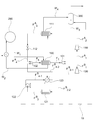
도 2는 본 출원의 예시적인 열 회수 장치(10)를 모식적으로 도시한 도면이다. 2 is a diagram schematically showing an exemplary
도 2와 같이 본 출원의 열 회수 장치(10)는, 제 1 순환 루프(R1) 및 제 2 순환 루프(R2)를 포함한다. 상기 제 1 및 제 2 순환 루프(R1, R2)는 냉매가 순환하도록 배관을 통해 연결된 순환 시스템일 수 있으며, 하나의 예시에서, 상기 제 1 순환 루프(R1)는 히트 펌프 사이클(Heat Pump Cycle)일 수 있고, 상기 제 2 순환 루프(R2)는 유기 랭킨 사이클(Organic Rankine Cycle, ORC)일 수 있다. 도 2에 나타나듯이, 상기 제 1 순환 루프(R1)는 증발기(100), 제 1 압축기(110), 제 1 응축기(111) 및 압력 강하 장치(112)를 포함하고, 예를 들어, 상기 증발기(100), 제 1 압축기(110), 제 1 응축기(111) 및 압력 강하 장치(112)는 배관을 통하여 연결될 수 있으며, 바람직하게는 상기 배관을 통하여 냉매 또는 유체가 흐를 수 있도록 유체 연결(fluidically connected)되어 있을 수 있다. 또한, 도 2와 같이, 상기 제 2 순환 루프(R2)는 또한, 증발기(100), 터빈(120), 제 2 응축기(121) 및 제 2 압축기(122)를 포함하고, 상기 증발기(100), 터빈(120), 제 2 응축기(121) 및 제 2 압축기(122)는 배관을 통하여 연결될 수 있으며, 바람직하게는 상기 배관을 통하여 냉매 또는 유체가 흐를 수 있도록 유체 연결(fluidically connected)되어 있을 수 있다. As shown in FIG. 2, the
하나의 예시에서, 상기 제 1 순환 루프(R1) 및 제 2 순환 루프(R2)는 증발기(Evaporator)를 공유한다. 일반적인, 히트 펌프 사이클과 유기 랭킨 사이클의 경우, 각각 증발기를 포함하며, 예를 들어, 상기 히트 펌프 사이클과 유기 랭킨 사이클을 단순 결합시킬 경우에는, 2기의 증발기를 필요로 하여, 우수한 성능 계수를 얻기 위하여, 과량의 에너지를 소모하여야 한다. 하지만 본 출원의 열 회수 장치에서는 1 기의 증발기만을 사용함으로써, 에너지 소모를 최소화하면서도 우수한 성능 계수를 가지는 열 회수 장치를 구현할 수 있다. 또한, 본 출원의 열 회수 장치(10)는 두 개의 상반되는 목적을 가진 공정, 즉, 전기를 이용하여 열을 생산하는 히트 펌프 사이클과 열을 사용하여 전기를 생산하는 유기 랭킨 사이클을 결합함으로써, 전기의 소비 없이 저온의 열을 고온의 열로 만들 수 있다. 또한, 본 출원의 열 회수 장치(10)에 의하면, 상기 열 회수 장치가 후술할 유체 분배기(101)를 포함함으로써, 유체의 흐름을 히트 펌프 사이클과 유기 랭킨 사이클로 적절히 분배할 수 있어, 상황에 따라 전기를 덜 사용하더라도 열 또는 스팀을 추가적으로 더 생산할 수 있도록 조절하거나 또는 고온의 스팀을 덜 생산하더라도 전기를 추가적으로 생산할 수 있도록 조절할 수 있고, 이에 따라, 운용 탄력성을 가지는 하이브리드 공정을 구현할 수 있다.In one example, the first circulation loop R 1 and the second circulation loop R 2 share an evaporator. In general, in the case of a heat pump cycle and an organic Rankine cycle, each of them includes an evaporator. For example, when the heat pump cycle and the organic Rankine cycle are simply combined, two evaporators are required, In order to obtain, excess energy must be consumed. However, in the heat recovery apparatus of the present application, by using only one evaporator, it is possible to realize a heat recovery apparatus having an excellent performance coefficient while minimizing energy consumption. In addition, the
예시적인 본 출원의 열 회수 장치에서는, 제 1 순환 루프(R1)와 제 2 순환 루프(R2)가 상기 증발기(100)를 공유하며, 이에 따라 상기 증발기(100)에서 유출되는 냉매 흐름은 분리된 후 제 1 순환 루프(R1)와 제 2 순환 루프(R2)를 각각 순환하며, 상기 제 1 순환 루프(R1)와 제 2 순환 루프(R2)를 순환한 냉매 흐름은 다시 합류된 후에 상기 증발기(100)로 유입될 수 있다. In the exemplary heat recovery apparatus of the present application, the first circulation loop R 1 and the second circulation loop R 2 share the
예를 들어, 상기 증발기(100)에서 유출되는 냉매 흐름(F1)은 유체 분배기(101)로 유입되고, 상기 유체 분배기로 유입된 냉매 흐름은 상기 유체 분배기에서 분리되어 유출될 수 있다. 이 경우, 상기 냉매 흐름의 일부(FA 1)는 제 1 순환 루프(R1)의 제 1 압축기(110)로 유입되고, 나머지 일부(FB 1)는 상기 제 2 순환 루프(R2)의 터빈(120)으로 유입될 수 있다. For example, the refrigerant flow F 1 flowing out of the
상기 유체 분배기(101)는 상기 증발기(100)에서 유출되는 냉매 흐름의 유량을 적절한 비율로 분배시키기 위하여, 본 출원의 열 교환 장치(10)에 포함될 수 있다. 상기 유체 분배기(101)에서 상기 증발기(100)에서 유출되는 냉매 흐름(F1)을 적절하게 배분하여 상기 제 1 순환 루프(R1) 및 제 2 순환 루프(R2)로 적절히 분배시킴으로써 히트 펌프 사이클과 상기 유기 랭킨 사이클이 결합되어 있는 본 출원의 열 회수 장치(10)가 1 기의 증발기만을 사용하는 경우에도, 상기 열 회수 장치(10)가 우수한 성능 계수를 가질 수 있다. 또한, 전술한 바와 같이, 상기 열 회수 장치(10)가 상기 유체 분배기(101)를 포함함으로써, 유체의 흐름을 히트 펌프 사이클과 유기 랭킨 사이클로 적절히 분배할 수 있어, 상황에 따라 전기를 덜 사용하더라도 열 또는 스팀을 추가적으로 더 생산할 수 있도록 조절하거나 또는 고온의 스팀을 덜 생산하더라도 전기를 추가적으로 생산할 수 있도록 조절할 수 있고, 이에 따라, 운용 탄력성을 가지는 하이브리드 공정을 구현할 수 있다.The
하나의 예시에서, 상기 증발기(100)에서 유출되는 냉매 흐름(F1)의 전체 유량에 대한 유체 분배기(101)에서 분리되어 제 1 압축기(110)로 유입되는 냉매 흐름(FA 1)의 유량의 비는 하기 일반식 1을 만족할 수 있다.In one example, the flow rate of the refrigerant flow F A 1 separated from the
[일반식 1][Formula 1]
0.3 ≤ Fc/Fe ≤ 0.5 0.3 ≤ F c / F e ≤ 0.5
상기 일반식 1에서, Fc는 유체 분배기(101)에서 분리되어 제 1 압축기(110)로 유입되는 냉매 흐름(FA 1)의 유량을 나타내고, Fe는 증발기(100)에서 유출되는 냉매 흐름(F1)의 전체 유량을 나타낸다.F c is the flow rate of the refrigerant flow F A 1 separated from the
즉, 상기 증발기(100)에서 유출되는 냉매 흐름(F1)의 전체 유량에 대한 유체 분배기(101)에서 분리되어 제 1 압축기(110)로 유입되는 냉매 흐름(FA 1)의 유량의 비 Fc/Fe는 0.3 내지 0.5, 예를 들어, 0.32 내지 0.45 또는 0.35 내지 0.4의 범위 내로 조절될 수 있으나, 이에 제한되는 것은 아니다.That is, the ratio of the flow rate of the refrigerant flow F A 1 separated from the
또한, 하나의 예시에서, 상기 증발기(100)에서 유출되는 냉매 흐름(F1)의 전체 유량에 대한 상기 유체 분배기(101)에서 분리되어 터빈(120)으로 유입되는 냉매 흐름(FB 1)의 유량의 비는 하기 일반식 2를 만족할 수 있다.In one example, the refrigerant flow F B 1 separated from the
[일반식 2][Formula 2]
0.5 ≤ Ft/Fe ≤ 0.70.5? Ft / Fe ? 0.7
상기 일반식 2에서, Ft는 유체 분배기(101)에서 분리되어 터빈(120)으로 유입되는 냉매 흐름(FB 1)의 유량을 나타내고, Fe는 증발기(100)에서 유출되는 냉매 흐름(F1)의 전체 유량을 나타낸다.Where F t represents the flow rate of the refrigerant flow F B 1 separated from the
즉, 상기 증발기(100)에서 유출되는 냉매 흐름(F1)의 전체 유량에 대한 상기 유체 분배기(101)에서 분리되어 터빈(120)으로 유입되는 냉매 흐름(FB 1)의 유량의 비 Ft/Fe는 0.5 내지 0.7, 예를 들어, 0.55 내지 0.68 또는 0.6 내지 0.65의 범위 내로 조절될 수 있으나, 이에 제한되는 것은 아니다.That is, the ratio F t of the flow rate of the coolant flow (F B 1) is separated from the
상기 증발기(100)에서 유출되는 냉매 흐름(F1)의 전체 유량에 대한 유체 분배기(101)에서 분리되어 제 1 압축기(110)로 유입되는 냉매 흐름(FA 1)의 유량의 비가 상기 일반식 1을 만족하고, 상기 증발기(100)에서 유출되는 냉매 흐름(F1)의 전체 유량에 대한 상기 유체 분배기(101)에서 분리되어 터빈(120)으로 유입되는 냉매 흐름(FB 1)의 유량의 비가 상기 일반식 2를 만족 함으로써, 본 출원의 열 회수 장치(10)는 1 기의 증발기만을 사용하는 경우에도, 우수한 성능 계수를 가질 수 있다.The ratio of the flow rate of the refrigerant flow F A 1 separated from the
상기 증발기(100)에서 유출되는 냉매 흐름(F1)의 전체 유량, 유체 분배기(101)에서 분리되어 제 1 압축기(110)로 유입되는 냉매 흐름(FA 1)의 유량 및 유체 분배기(101)에서 분리되어 터빈(120)으로 유입되는 냉매 흐름(FB 1)의 유량은 상기 일반식 1 및 일반식 2를 만족한다면, 특별히 제한되는 것은 아니며, 적용하고자 하는 공정의 종류 및 각 공정의 조건에 따라 다양하게 조절할 수 있다. 하나의 예시에서, 상기 증발기(100)에서 유출되는 냉매 흐름(F1)의 전체 유량은 10,000 kg/hr 내지 100,000 kg/hr, 예를 들어, 20,000 kg/hr 내지 90,000 kg/hr 또는 30,000 kg/hr 내지 80,000 kg/hr일 수 있으며, 바람직하게는, 45,000 kg/hr 내지 55,000 kg/hr일 수 있으나, 이에 제한되는 것은 아니다. 또한, 상기 유체 분배기(101)에서 분리되어 제 1 압축기(110)로 유입되는 냉매 흐름(FA 1)의 유량은 5,000 kg/hr 내지 40,000 kg/hr, 예를 들어, 8,000 kg/hr 내지 35,000 kg/hr 또는 10,000 kg/hr 내지 30,000 kg/hr일 수 있으며, 바람직하게는, 15,000 kg/hr 내지 25,000 kg/hr일 수 있으나, 이에 제한되는 것은 아니다. 또한, 상기 유체 분배기(101)에서 분리되어 터빈(120)으로 유입되는 냉매 흐름(FB 1)의 유량은 5,000 kg/hr 내지 60,000 kg/hr, 예를 들어, 10,000 kg/hr 내지 50,000 kg/hr 또는 20,000 kg/hr 내지 40,000 kg/hr일 수 있으며, 바람직하게는, 25,000 kg/hr 내지 35,000 kg/hr일 수 있으나, 이에 제한되는 것은 아니다. The total flow rate of the refrigerant flow F 1 flowing out of the
상기 증발기(100)는, 냉매 흐름과 외부에서 유입되는 제 1 유체 흐름을 열교환시키기 위하여, 본 출원의 열 회수 장치(10)에 포함되며, 상기 열교환을 통하여, 냉매는 기화된 후 상기 증발기(100)로 유입되는 흐름보다 상대적으로 고온의 기상 흐름으로 상기 증발기(100)로부터 유출될 수 있다. 상기에서 「기상」은 냉매 흐름 전체 성분 중 기체 성분 흐름이 농후(rich)한 상태를 의미하며, 예를 들어, 상기 냉매 흐름 전체 성분 중 기체 성분 흐름의 몰분율이 0.9 내지 1.0인 상태를 의미한다.The
상기 증발기(100)로 유입되는 제 1 유체 흐름(W1)은, 예를 들어, 폐열 흐름 또는 응축기를 통과한 응축수의 흐름일 수 있으며, 상기 폐열 흐름은, 예를 들어, 발열 반응기의 냉각수일 수 있으나, 이제 제한되는 것은 아니다. 본 출원에서는 특히, 100℃ 미만, 예를 들어, 50 내지 90℃ 수준의 현열 상태의 저급 열원의 폐열 흐름을 바람직하게 사용할 수 있다. The first fluid stream W 1 flowing into the
예를 들어, 상기 증발기(100)로는 유체 연결된 배관을 통하여 냉매 흐름(F5) 및 폐열 흐름 등의 제 1 유체 흐름(W1)이 유입될 수 있으며, 유입된 상기 냉매 흐름(F5) 및 제 1 유체 흐름(W1)은 상기 증발기(100)에서 상호 열교환된 후에, 상기 유체 연결된 배관을 통하여 상기 증발기(100)에서 각각 유출될 수 있다. For example, a first fluid flow W 1 such as a refrigerant flow F 5 and a waste heat flow can be introduced into the
하나의 예시에서, 상기 증발기(100)에서 유출되는 냉매 흐름(F1)의 온도와 상기 증발기(100)로 유입되는 제 1 유체 흐름(W1)의 온도는 하기 일반식 3을 만족할 수 있다.In one example, the temperature of the refrigerant flow F 1 flowing out of the
[일반식 3][Formula 3]
1℃ ≤ TEin - TEout ≤ 20℃1 ° C ≤ T Ein - T Eout ≤ 20 ° C
상기 일반식 3에서, TEin는 증발기(100)로 유입되는 제 1 유체 흐름(W1)의 온도를 나타내고, TEout은 상기 증발기(100)에서 유출되는 냉매 흐름(F1)의 온도를 나타낸다.T Ein represents the temperature of the first fluid flow W 1 flowing into the
즉, 상기 증발기(100)에서 유출되는 냉매 흐름(F1)의 온도와 상기 증발기(100)로 유입되는 제 1 유체 흐름(W1)의 온도의 차 TEin - TEout는 1 내지 20℃, 예를 들어, 1 내지 15℃, 2 내지 20℃, 1 내지 10℃ 또는 2 내지 10℃의 범위로 조절될 수 있다.That is, the difference T Ein -T Eout between the temperature of the refrigerant flow F 1 flowing out of the
상기 증발기(100)에서 유출되는 냉매 흐름(F1)의 온도와 상기 증발기(100)로 유입되는 제 1 유체 흐름(W1)의 온도가 상기 일반식 3을 만족함으로써, 저온의 폐열, 특히, 100℃ 미만, 예를 들어, 50 내지 90℃ 수준의 현열 상태의 저급 열원의 폐열을 이용하여, 고온의 스팀을 생산할 수 있다. When the temperature of the refrigerant flow F 1 flowing out of the
상기 증발기(100)에서 유출되는 냉매 흐름(F1)의 온도와 상기 증발기(100)로 유입되는 제 1 유체 흐름(W1)의 온도는 상기 일반식 3을 만족한다면, 특별히 제한되는 것은 아니며, 적용하고자 하는 공정의 종류 및 각 공정의 조건에 따라 다양하게 조절할 수 있다. 하나의 예시에서, 상기 증발기(100)로 유입되는 제 1 유체 흐름(W1)의 온도는 60℃ 내지 100℃, 예를 들어, 70℃ 내지 90℃, 80℃ 내지 95℃, 80℃ 내지 85℃ 또는 83℃ 내지 87℃일 수 있으나, 특별히 이에 제한되는 것은 아니다. 또한, 상기 증발기(100)에서 유출되는 냉매 흐름(F1)의 온도는, 60℃ 내지 100℃, 예를 들어, 60℃ 내지 95℃, 65℃ 내지 90℃, 65℃ 내지 95℃, 또는 70℃ 내지 85℃일 수 있으나, 특별히 이에 제한되는 것은 아니다. The temperature of the first fluid flow (W 1) flowing in the temperature and the
이 경우, 상기 증발기(100)에서 상기 냉매 흐름과 열교환된 후에 유출되는 상기 유체 흐름(W2)의 온도는 60℃ 내지 100℃, 예를 들어, 60℃ 내지 95℃, 65℃ 내지 90℃, 65℃ 내지 95℃, 또는 70℃ 내지 85℃일 수 있으나, 특별히 이에 제한되는 것은 아니다.In this case, the temperature of the fluid flow (W 2 ) flowing out after the heat exchange with the refrigerant flow in the
또한, 상기 증발기(100)로 유입되는 냉매 흐름(F5)의 온도는, 상기 증발기(100)로 유입되는 유체 흐름(W1)의 온도보다는 낮은 온도, 예를 들어, 40℃ 내지 90℃, 40℃ 내지 80℃, 45℃ 내지 45℃ 또는 73℃ 내지 77℃일 수 있으나, 이에 제한되는 것은 아니다. The temperature of the refrigerant flow F 5 flowing into the
상기 증발기(100)로 유입되고, 유출되는 냉매 흐름(F5, F1)의 압력은 냉매의 종류 및 운전 조건에 따라 달라질 수 있으며, 특별히 제한되는 것은 아니다. 예를 들어, 상기 증발기(100)로 유입되고, 유출되는 냉매 흐름(F5, F1)의 압력은 2.0 kgf/cm2g 내지 20.0 kgf/cm2g, 예를 들어, 2.0 kgf/cm2g 내지 10.0 kgf/cm2g 또는 2.1 kgf/cm2g 내지 7.0 kgf/cm2g일 수 있으나, 이에 제한되는 것은 아니다. 상기 냉매 흐름의 압력을 2.0 kgf/cm2g 내지 20.0 kgf/cm2g로 조절함으로써, 상기 제 1 압축기(110)의 압축비를 용이하게 조절할 수 있다. 일반적으로, 압축기의 유출 압력은 온도에 따라 정해지나, 유입 압력이 높아지면, 압축비를 낮게 유지할 수 있다. 상기 압축비가 높아질수록, 저온의 열원으로부터 고온의 스팀을 생성할 수 있으나, 이 경우, 성능 계수가 감소하게 되며, 압축비가 낮아질수록, 성능 계수는 증가하나, 저온의 열원으로부터 고온의 스팀을 생성하기 어려운 문제가 발생한다. 상기에서, 압력 단위 kgf/cm2g는 계기 압력(gauge pressure)을 의미한다.The pressure of the refrigerant flows F 5 and F 1 flowing into and out of the
상기 증발기(100)로 유입되고, 유출되는 제 1 유체 흐름(W1, W2)의 압력은 특별히 제한되는 것은 아니며, 예를 들면, 0.5 kgf/cm2g 내지 2.0 kgf/cm2g, 예를 들어, 0.7 kgf/cm2g 내지 1.5 kgf/cm2g 또는 0.8 kgf/cm2g 내지 1.2 kgf/cm2g일 수 있다. The pressure of the first fluid flows (W 1 , W 2 ) flowing into and out of the
또한, 상기 증발기(100)로 유입되는 제 1 유체 흐름(W1)의 유량은 50,000 kg/hr 이상, 예를 들어, 100,000 kg/hr 이상, 또는 200,000 kg/hr 이상일 수 있으며, 바람직하게는, 250,000 kg/hr 이상일 수 있으나, 이에 제한되는 것은 아니다. 상기 증발기(100)로 유입되는 제 1 유체 흐름(W1)의 유량이 증가할수록, 동일한 열량을 냉매로 전달해도 열전달 후 유출되는 유체 흐름(W2)의 유출 온도가 높게 유지되어, 증발기(100)에서 유출되는 냉매 흐름(F1)의 유출 온도도 높게 유지할 수 있다. 따라서, 상기 증발기(100)로 유입되는 제 1 유체 흐름(W1)의 유량의 상한은 특별히 제한되는 것은 아니며, 상기 장치의 효율성 및 경제성을 고려하여, 예를 들면, 500,000 kg/hr 이하, 또는 350,000 kg/hr 이하일 수 있으나, 이에 제한되는 것은 아니다.The flow rate of the first fluid flow W 1 flowing into the
상기 제 1 순환 루프(R1)에서, 상기 제 1 압축기(110)는, 상기 증발기(100)에서 유출되는 기상의 냉매 흐름(F1)을 압축시키고 온도 및 압력을 상승시키기 위하여, 본 출원의 열 회수 장치(10)에 포함되며, 상기 제 1 압축기(110)를 통과하여 압축되고, 상기 증발기(100)에서 유출되는 냉매 흐름(F1)에 비하여 상대적으로 고온 및 고압의 기상의 냉매 흐름(FA 2)은 후술할 제 1 응축기(111)로 유입될 수 있다. In the first circulation loop R 1 , the
예를 들어, 증발기(100)에서 유출되는 냉매 흐름(F1)은 상술한 유체 분배기(101)에서 분배된 후 유체 연결된 배관을 통하여 상기 제 1 압축기(110)로 유입될 수 있으며, 유입된 상기 냉매 흐름(FA 1)은 상기 제 1 압축기(110)에서 압축된 후에, 상기 유체 연결된 배관을 통하여 유출(FA 2)될 수 있다.For example, the refrigerant flow F 1 flowing out of the
하나의 예시에서, 상기 유체 분배기(101)에서 분리되어 제 1 압축기(110)로 유입되는 냉매 흐름(FA 1)의 압력과 제 1 압축기(110)에서 유출되는 냉매 흐름(FA 2)의 압력의 비는 하기 일반식 4를 만족할 수 있다.In one example, the pressure of the refrigerant flow F A 1 separated from the
[일반식 4][Formula 4]
2 ≤ PC1out/PCin ≤ 52? P C1out / P Cin ? 5
상기 일반 4에서, PC1out은 상기 제 1 압축기(110)에서 유출되는 냉매 흐름(FA 2)의 압력(bar)을 나타내고, PC1in은 유체 분배기(101)에서 분리되어 상기 제 1 압축기(110)로 유입되는 냉매 흐름(FA 1)의 압력(bar)을 나타낸다.In the normal 4, P C1out represents the pressure (bar) of the coolant flow (F A 2) flowing out of the first compressor (110), P C1in is separated from the
즉, 상기 유체 분배기(101)에서 분리되어 제 1 압축기(110)로 유입되는 냉매 흐름(FA 1)의 압력과 제 1 압축기(110)에서 유출되는 냉매 흐름(FA 2)의 압력의 비 PC1out/PCin는 2 내지 5, 예를 들어, 2 내지 4, 바람직하게는 3 내지 4의 범위로 조절될 수 있다. 상기 압력의 비 PC1out/PCin는 상기 유체 분배기(101)에서 분리되어 제 1 압축기(110)로 유입되는 냉매 흐름(FA 1)의 압력 및 제 1 압축기(110)에서 유출되는 냉매 흐름(FA 2)의 압력의 단위가 bar인 경우를 기초로 하여 계산된 값이며, 측정되는 압력의 단위에 따라 환산되는 구체적인 압력의 값이 달라지는 경우, 상기 압력의 비가 일반식 4를 만족하지 않을 수 있는 것은 기술분야에서 자명하다. 따라서, 상기 일반식 4는 측정된 압력의 값을 bar의 압력 단위로 환산하여 만족하는 모든 경우를 포함할 수 있다.That is, the ratio of the pressure of the refrigerant flow F A 1 separated from the
상기 유체 분배기(101)에서 분리되어 제 1 압축기(110)로 유입되는 냉매 흐름(FA 1)의 압력과 제 1 압축기(110)에서 유출되는 냉매 흐름(FA 2)의 압력의 비가 상기 일반식 4를 만족함으로써, 상기 증발기(100)에서 기화된 냉매는 후술할 제 1 응축기(111)를 통과하는 유체 흐름과 열교환되기에 충분한 열량을 가지도록 고온 및 고압 상태로 압축될 수 있다. The ratio between the pressure of the refrigerant flow F A 1 separated from the
상기 유체 분배기(101)에서 분리되어 제 1 압축기(110)로 유입되는 냉매 흐름(FA 1)의 압력과 제 1 압축기(110)에서 유출되는 냉매 흐름(FA 2)의 압력은 상기 일반식 4를 만족한다면, 특별히 제한되는 것은 아니며, 적용하고자 하는 공정의 종류 및 각 공정의 조건에 따라 다양하게 조절할 수 있다. 하나의 예시에서, 상기 유체 분배기(101)에서 분리되어 제 1 압축기(110)로 유입되는 냉매 흐름(FA 1)의 압력은 2.0 kgf/cm2g 내지 20 kgf/cm2g, 예를 들어, 2.0 kgf/cm2g 내지 10.0 kgf/cm2g 또는 2.1 kgf/cm2g 내지 7.0 kgf/cm2g일 수 있으나, 이에 제한되는 것은 아니다. 또한, 상기 제 1 압축기(110)에서 유출되는 냉매 흐름(FA 2)의 압력은 15 내지 30 kgf/cm2g, 예를 들어, 18 내지 30 kgf/cm2g, 또는 20 내지 30 kgf/cm2g일 수 있으나, 이에 제한되는 것은 아니다. The pressure of the refrigerant flow F A 1 separated from the
또한, 상기 제 1 압축기(110)에서 압축된 후에 유출되는 상기 냉매 흐름(FA 2)의 온도는 110℃ 내지 170℃, 예를 들어, 120℃ 내지 150℃, 또는 123℃ 내지 165℃일 수 있으나, 이에 제한되는 것은 아니다. The temperature of the refrigerant flow F A 2 flowing out after being compressed by the
상기 제 1 압축기(110)로는, 기상의 흐름을 압축시킬 수 있는 압축 장치라면, 기술 분야에서 알려진 다양한 압축 장치를 제한 없이 사용할 수 있으며, 하나의 예시에서, 상기 제 1 압축기(110)는 콤프레셔일 수 있으나, 이에 제한되는 것은 아니다.As the
상기 제 1 순환 루프(R1)에서, 상기 제 1 응축기(111)는, 상기 제 1 압축기(110)에서 유출된 고온 및 고압의 냉매 흐름(FA 2)과 외부에서 유입되는 제 2 유체 흐름(W3)을 열교환시키기 위하여, 본 출원의 열 회수 장치(10)에 포함되며, 상기 열교환을 통하여, 냉매는 응축된 후 상기 제 1 압축기(110)에서 유출되는 냉매 흐름(FA 2)에 비하여 상대적으로 저온의 액상 흐름으로 유출(FA 3)될 수 있으며, 상기 제 2 유체 흐름(W3)은 상기 냉매가 응축시에 발생하는 잠열을 흡수할 수 있다. 상기에서 「액상」은 냉매 흐름 전체 성분 중 액체 성분 흐름이 농후한 상태를 의미하며, 예를 들어, 상기 냉매 흐름 전체 성분 중 액체 성분 흐름의 몰분율이 0.9 내지 1.0인 상태를 의미한다.In the first circulation loop R 1 , the
하나의 예시에서, 상기 제 1 응축기(111)로 유입되는 제 2 유체는 물(make-up water)일 수 있으며, 이 경우, 상기 제 1 응축기(111)에서 열교환된 물은 상기 냉매가 응축시에 발생하는 잠열을 흡수하여 기화되고, 스팀 형태로 배출될 수 있다. In one example, the second fluid introduced into the
예를 들어, 상기 제 1 응축기(111)로는 유체 연결된 배관을 통하여 제 1 압축기로부터 유출된 냉매 흐름(FA 2) 및 상기 냉매 흐름을 열교환 시키기 위한 제 2 유체 흐름(W3)이 유입될 수 있으며, 유입된 상기 냉매 흐름(FA 2) 및 제 2 유체 흐름(W3)은 상기 제 1 응축기(111)에서 상호 열교환된 후에, 상기 유체 연결된 배관을 통하여 상기 제 1 응축기(111)에서 각각 유출될 수 있다. For example, a first refrigerant flow (F A 2 ) flowing out of the first compressor and a second fluid flow (W 3 ) for heat-exchanging the refrigerant flow may be introduced into the
상기 제 1 응축기(111)로 유입되는 제 2 유체 흐름(W3)의 온도 및 압력은 특별히 제한되지 않으며, 다양한 온도 및 압력의 유체 흐름을 상기 제 1 응축기로 유입시킬 수 있다. 예를 들어, 110℃ 내지 120℃, 예를 들어, 112℃ 내지 116℃, 또는 115℃ 내지 118℃의 온도 및 0.5 내지 0.9 kgf/cm2g, 예를 들어, 0.6 내지 0.8 kgf/cm2g의 압력으로 제 2 유체 흐름(W3)을 상기 제 1 응축기(111)로 유입될 수 있다.The temperature and pressure of the second fluid flow W 3 flowing into the
또한, 상기 제 1 응축기(111)로 유입되는 제 2 유체 흐름(W3)의 유량은, 특별히 제한되는 것은 아니며, 300 kg/hr 내지 6,000 kg/hr, 예를 들어, 500 kg/hr 내지 1,000 kg/hr, 800 kg/hr 내지 2,000 kg/hr, 또는, 900 kg/hr 내지 1,100 kg/hr일 수 있다.The flow rate of the second fluid flow W 3 flowing into the
하나의 예시에서, 상기 제 1 압축기(110)에서 유출된 냉매(FA 2)와 상기 제 1 응축기에서 열교환된 물(W4)은 115℃ 내지 150℃, 예를 들어, 115℃ 내지 145℃ 120℃ 내지 140℃, 또는 115℃ 내지 137℃의 온도 및 0.5 내지 2.5 kgf/cm2g, 예를 들어, 0.7 내지 2.2 kgf/cm2g의 압력을 가지는 스팀으로 상기 제 1 응축기(111)에서 유출될 수 있다.In one example, the refrigerant (F A 2 ) flowing out of the first compressor (110) and the water (W 4 ) heat-exchanged in the first condenser are heated to a temperature of 115 ° C to 150 ° C, 120 ℃ to 140 ℃, or the 115 ℃ to 137 ℃ temperature and 0.5 to 2.5 kgf / cm 2 g of, for example, 0.7 to steam having a pressure of 2.2 kgf / cm 2 g in the
또한, 상기 제 1 응축기(111)에서 상기 제 2 유체 흐름(W3)과 열교환된 냉매 흐름(FA 3)은 115℃ 내지 150℃, 예를 들어, 115℃ 내지 145℃ 또는 120℃ 내지 145℃, 바람직하게는 124℃ 내지 143℃의 온도로 상기 제 1 응축기(111)에서 유출될 수 있으나, 이에 제한되는 것은 아니다. 상기 제 1 응축기(111)에서 상기 제 2 유체 흐름(W3)과 열교환된 냉매 흐름(FA 3)의 압력은, 냉매의 종류 및 운전 조건에 따라 다양하게 변할 수 있으며, 예를 들어, 15 내지 30 kgf/cm2g, 18 내지 29.5 kgf/cm2g, 또는 20 내지 29.3 kgf/cm2g의 압력으로 상기 제 1 응축기(111)에서 유출(FA 3)될 수 있으나, 이에 제한되는 것은 아니다. The refrigerant flow F A 3 exchanged with the second fluid flow W 3 in the
예시적인 본 출원의 열 회수 장치(10)는 또한, 저장 탱크(300)를 추가로 포함할 수 있다. 도 2에 나타나듯이, 상기 저장 탱크(300)는 제 1 응축기(111)와 배관을 통해 유체 연결된 상태로 구비될 수 있다. 상기 저장 탱크(300)는 제 1 응축기(111)로 유입되는 유체 흐름을 공급하기 위한 장치로서, 상기 저장 탱크(300)에는, 제 1 응축기(111)로 유입되는 유체, 예를 들어, 물이 저장되어 있을 수 있다. The exemplary
상기 저장 탱크(300)에서 유출된 제 2 유체 흐름(W3)은 배관을 따라 제 1 응축기(111)로 유입되며, 상기 제 1 응축기(111)로 유입된 냉매 흐름(FA 2)과 열교환될 수 있다. 이 경우, 상기 열교환된 유체 흐름(W4), 예를 들어, 고온 고압의 물은 상기 저장 탱크로 재유입 된 후, 감압 되어, 스팀 형태로 배출될 수 있다.The second fluid flow W 3 flowing out from the
상기 압력 강하 장치(112)는, 상기 제 1 응축기(111)에서 유출되는 고온, 고압 및 액상의 냉매 흐름(FA 3)을 팽창시키고 온도 및 압력을 낮추기 위하여, 본 출원의 열 회수 장치(10)에 포함되며, 상기 압력 강하 장치(112)를 통과한, 냉매 흐름(FA 4)은 팽창된 후 상기 제 1 응축기(111)에서 유출되는 냉매 흐름(111)에 비하여 상대적으로 저온 및 저압 상태로 전술한 증발기(100)로 재유입될 수 있다.The
예를 들어, 제 1 응축기(111)에서 유출되는 냉매 흐름(FA 3)은 유체 연결된 배관을 통하여 상기 압력 강하 장치(112)로 유입될 수 있으며, 유입된 상기 냉매 흐름은 상기 압력 강하 장치(112)에서 팽창된 후에, 상기 제 1 응축기(111)에서 유출되는 냉매 흐름(FA 3)에 비하여 상대적으로 저온 및 저압 상태로 상기 유체 연결된 배관을 통하여 유출(FA 4)될 수 있다. 하나의 예시에서, 상기 압력 강하 장치(112)에서 유출되는 냉매 흐름(FA 4)은 40℃ 내지 90℃, 예를 들어, 40℃ 내지 80℃ 또는 45℃ 내지 85℃, 바람직하게는 45℃ 내지 77℃의 온도로 상기 압력 강하 장치(112)에서 유출될 수 있으나, 이에 제한되는 것은 아니다. 또한, 상기 압력 강하 장치(112)에서 유출되는 냉매 흐름(FA 4)의 압력은, 냉매의 종류 및 운전 조건에 따라 다양하게 변할 수 있으며, 예를 들어, 2.0 kgf/cm2g 내지 10 kgf/cm2g, 예를 들어, 2.5 kgf/cm2g 내지 8.0 kgf/cm2g 또는 2.2 kgf/cm2g 내지 7.0 kgf/cm2g일 수 있으며, 바람직하게는 2.0 kgf/cm2g 내지 6.5 kgf/cm2g의 압력으로 상기 압력 강하 장치(112)에서 유출될 수 있으나, 이에 제한되는 것은 아니다.For example, a first refrigerant flow (F A 3) flowing out of the
상기 제 1 순환 루프에서, 상기 압력 강하 장치(112)는, 예를 들어 상기 제 1 응축기(111)에서 유출된 냉매 흐름(FA 3)이 흐르는 배관에 설치된 컨트롤 밸브 또는 터빈일 수 있다. In the first circulation loop, the
상기 압력 강하 장치(112)가 터빈일 경우, 상기 터빈은 발전 장치일 수 있으며, 예를 들어, 배관을 통해 흐르는 냉매, 즉 유체의 역학적 에너지를 전기 에너지로 변환시킬 수 있는 수차(hydraulic turbine)일 수 있으며, 상기 수차를 이용할 경우, 제 1 압축기(110)에서 소모되는 전력을 열 회수 장치(10) 자체적으로 생산할 수 있으므로, 상기 회수 장치의 성능 계수를 증가시킬 수 있다.When the
상기 제 2 순환 루프(R2)에서 터빈(120)은 제 1 압축기(110)에 사용되는 전기를 생산하기 위하여 본 출원의 열 회수 장치(10)에 포함되고, 상기 증발기(100)에서 유출되는 기상의 냉매 흐름(F1)이 상기 터빈(120)으로 유입되고, 상기 터빈(120)에서 팽창되면서 온도 및 압력이 낮아지게 될 경우, 엔탈피를 잃어버리게 되며, 상기 잃어버린 엔탈피 만큼 상기 터빈(120)에서는 일이 발생한다. 상기 터빈(120)에서 발생한 일은 전술한 제 1 압축기(110)에서 압축 시에 사용될 수 있다. In the second circulation loop R 2 , the
상기 터빈(120)을 통과하여 팽창되고, 상기 증발기(100)에서 유출되는 냉매 흐름(F1)에 비하여 상대적으로 저온 및 저압의 기상의 냉매 흐름(FB 2)은 후술할 제 2 응축기(121)로 유입될 수 있다. 예를 들어, 증발기(100)에서 유출되는 냉매 흐름(F1)은 상술한 유체 분배기(101)에서 분배된 후 유체 연결된 배관을 통하여 상기 터빈(120)으로 유입(FB 1)될 수 있으며, 유입된 상기 냉매 흐름(FB 1)은 상기 터빈(120)에서 팽창된 후에, 상기 유체 연결된 배관을 통하여 유출(FB 2)될 수 있다. Is expanded through the
상기 제 2 순환 루프(R2)에서, 상기 제 2 응축기(121)는, 상기 터빈(120)에서 유출된 저온 및 저압의 냉매 흐름(FB 2)을 응축시키기 위하여, 본 출원의 열 회수 장치(10)에 포함되며, 상기 제 2 응축기(121)를 통하여, 냉매는 응축된 후 상기 터빈에서 유출되는 냉매 흐름(FB 2)에 비하여 상대적으로 저온 및 저압의 액상 흐름으로 유출(FB 3)될 수 있다. In the second circulation loop R 2 , the
상기 제 2 순환 루프(R2)에서, 상기 제 2 압축기(122)는, 상기 제 2 응축기(121)에서 유출되는 액상의 냉매 흐름(FB 3)을 압축시키고 온도 및 압력을 상승시키기 위하여, 본 출원의 열 회수 장치(10)에 포함되며, 상기 제 2 압축기(122)를 통과하여 압축된 후, 상기 제 2 응축기(121)에서 유출되는 냉매 흐름(FB 3)에 비하여 상대적으로 고온 및 고압의 기상의 냉매 흐름(FB 4)은 유체 혼합기(102)로 유입된 후에 전술한 증발기(100)로 유입될 수 있다. In the second circulation loop R 2 , the
예를 들어, 제 2 응축기(121)에서 유출되는 냉매 흐름(FB 3)은 유체 연결된 배관을 통하여 상기 제 2 압축기(122)로 유입될 수 있으며, 유입된 상기 냉매 흐름(FB 3)은 상기 제 2 압축기(122)에서 압축된 후에, 상기 유체 연결된 배관을 통하여 유출(FB 4)될 수 있다.For example, the refrigerant flow F B 3 flowing out of the
하나의 예시에서, 상기 제 2 응축기(121)에서 유출되어 제 2 압축기(122)로 유입되는 냉매 흐름(FB 3)의 압력과 상기 제 2 압축기(122)에서 유출되는 냉매 흐름(FB 4)의 압력의 비가 하기 일반식 5를 만족할 수 있다.In one example, the pressure of the refrigerant flow F B 3 flowing out of the
[일반식 5][Formula 5]
2 ≤ PC2out/PC2in ≤ 72? P C2out / P C2in ? 7
상기 일반식 5에서, PC2out는 상기 제 2 압축기(122)에서 유출되는 냉매 흐름(FB 4)의 압력(bar)을 나타내고, PC2in는 제 2 응축기(121)에서 유출되어 제 2 압축기(122)로 유입되는 냉매 흐름(FB 3)의 압력(bar)을 나타낸다. In
즉, 상기 제 2 응축기(121)에서 유출되어 제 2 압축기(122)로 유입되는 냉매 흐름(FB 3)의 압력과 제 2 압축기(122)에서 유출되는 냉매 흐름(FB 4)의 압력의 비 PC2out/PC2in는 2 내지 7, 예를 들어, 2 내지 5, 바람직하게는 2.5 내지 4.5의 범위로 조절될 수 있다. 상기 압력의 비 PC2out/PC2in는 상기 제 2 응축기(121)에서 유출되어 제 2 압축기(122)로 유입되는 냉매 흐름(FB 3)의 압력 및 상기 제 2 압축기(122)에서 유출되는 냉매 흐름(FB 4)의 압력의 단위가 bar인 경우를 기초로 하여 계산된 값이며, 측정되는 압력의 단위에 따라 환산되는 구체적인 압력의 값이 달라지는 경우, 상기 압력의 비가 일반식 5를 만족하지 않을 수 있는 것은 기술분야에서 자명하다. 따라서, 상기 일반식 5는 측정된 압력의 값을 bar의 압력 단위로 환산하여 만족하는 모든 경우를 포함할 수 있다.That is, the pressure of the refrigerant flow F B 3 flowing out from the
상기 제 2 응축기(121)에서 유출되어 제 2 압축기(122)로 유입되는 냉매 흐름(FB 3)의 압력과 제 2 압축기(122)에서 유출되는 냉매 흐름(FB 4)의 압력의 비가 상기 일반식 5를 만족함으로써, 상기 터빈(120)에서 전기를 발생시키고 떨어진 압력을 보충하기에 충분할 정도로 압축될 수 있다. The ratio of the pressure of the refrigerant flow F B 3 flowing out of the
상기 제 2 응축기(121)에서 유출되어 제 2 압축기(122)로 유입되는 냉매 흐름(FB 3)의 압력과 제 2 압축기(122)에서 유출되는 냉매 흐름의 압력(FB 4)은 상기 일반식 5를 만족한다면, 특별히 제한되는 것은 아니며, 적용하고자 하는 공정의 종류 및 각 공정의 조건에 따라 다양하게 조절할 수 있다. 하나의 예시에서, 상기 제 2 응축기(121)에서 유출되어 제 2 압축기(122)로 유입되는 냉매 흐름(FB 3)의 압력은 0.5 kgf/cm2g 내지 3.0 kgf/cm2g, 예를 들어, 1.2 kgf/cm2g 내지 2.5 kgf/cm2g 또는 1.0 kgf/cm2g 내지 2.0 kgf/cm2g일 수 있으나, 이에 제한되는 것은 아니다. 또한, 상기 제 2 압축기(122)에서 유출되는 냉매 흐름(FB 4)의 압력은 2.0 kgf/cm2g 내지 20.0 kgf/cm2g, 예를 들어, 2.0 kgf/cm2g 내지 10.0 kgf/cm2g 또는 2.2 kgf/cm2g 내지 7.0 kgf/cm2g일 수 있으나, 이에 제한되는 것은 아니다. The pressure of the refrigerant flow F B 3 flowing out of the
상기 제 2 압축기(122)에서 압축된 후에 유출되는 상기 냉매 흐름(FB 4)은, 전술한 제 1 순환 루프(R1)의 압력 강하 장치(112)에서 유출되는 냉매 흐름(FA 4)과 상기 유체 혼합기(102)에서 합쳐진 후에 상기 증발기(100)로 유입될 수 있다.The refrigerant flow F B 4 flowing out after being compressed by the
상기 제 2 압축기(122)로는, 액상의 흐름을 압축시킬 수 있는 압축 장치라면, 기술 분야에서 알려진 다양한 압축 장치를 제한 없이 사용할 수 있으며, 하나의 예시에서, 상기 제 2 압축기(122)는 펌프일 수 있으나, 이에 제한되는 것은 아니다.As the
본 출원의 열 회수 장치(10)에서는, 상기 제 1 순환 루프(R1)에 포함되는, 증발기(100), 제 1 압축기(110), 제 1 응축기(111) 및 압력 강하 장치(112)를 통과하는 냉매 흐름 및 제 2 순환 루프(R2)에 포함되는 증발기(100), 터빈(120), 제 2 응축기(121) 및 제 2 압축기(122)를 통과하는 냉매 흐름이 각각 상이한 온도 및 압력 특성을 가지며, 기상 및/또는 액상의 흐름으로 상기 증발기(100), 제 1 압축기(111), 제 1 응축기(111), 압력 강하 장치(112), 터빈(120), 제 2 응축기(121) 및 제 2 압축기(122)로 유입 또는 유출됨으로써, 상기 냉매 흐름의 온도, 압력 및 상태 변화에 따른 잠열을 스팀 생성을 위한 열원으로서 사용할 수 있다. 또한, 본 출원의 열 회수 장치(10)에서는, 100℃ 미만의 저온의 폐열을 이용하여 스팀을 생성하기 위한 최적의 온도 및 압력 조건을 설정함으로써, 우수한 효율로 스팀을 생성할 수 있다.In the
하나의 예시에서, 상기 증발기(100)로 유입되는 냉매 흐름(F5)은 액상의 흐름일 수 있으며, 상기 냉매 흐름 내의 액상 흐름의 부피 분율은 0.8 내지 1.0, 예를 들어, 0.9 내지 1.0, 바람직하게는 0.99 내지 1.0일 수 있다. In one example, the refrigerant flow F 5 entering the
또한, 상기 제 1 압축기(110) 또는 터빈(120)에서 유출되는 냉매 흐름(FA 2, FB 2)은 기상의 흐름일 수 있으며, 상기 냉매 흐름 내의 기상 흐름의 부피 분율은 0.8 내지 1.0, 예를 들어, 0.9 내지 1.0, 바람직하게는 0.99 내지 1.0일 수 있다.The refrigerant flow (F A 2 , F B 2 ) flowing out of the first compressor (110) or the turbine (120) may be a gaseous flow, the volume fraction of the gaseous stream in the refrigerant flow being 0.8 to 1.0, For example, 0.9 to 1.0, preferably 0.99 to 1.0.
상기 제 1 응축기(111), 제 2 응축기(121) 또는 제 2 압축기(122)에서 유출되는 냉매 흐름(FA 3, FB 3, FB 4)은 액상의 흐름일 수 있으며, 상기 냉매 흐름 내의 액상 흐름의 부피 분율은 0.8 내지 1.0, 예를 들어, 0.9 내지 1.0, 바람직하게는 0.99 내지 1.0일 수 있다.The refrigerant flows F A 3 , F B 3 and F B 4 flowing out from the
또한, 상기 압력 강하 장치(112)에서 유출된 냉매 흐름(FA 4)은 액상의 흐름일 수 있으며, 상기 냉매 흐름 내의 기상 흐름의 분율은 0 내지 0.2, 예를 들어, 0 내지 0.15, 바람직하게는 0 내지 0.1일 수 있다.Also, the refrigerant flow F A 4 flowing out of the
상기에서, 부피 분율(volume fraction)은 상기 배관을 통하여 흐르는 냉매 흐름 전체의 체적 유량(volume flow rate)에 대한 액상 흐름 또는 기상 흐름의 체적 유량의 비율을 의미하며, 상기 체적 유량은 단위 시간당 흐르는 유체의 체적을 나타내며, 하기 일반식 7에 의하여 구할 수 있다.The volume fraction refers to the ratio of the volume flow rate of the liquid flow or gas phase flow to the volume flow rate of the entire refrigerant flow flowing through the pipe, And can be obtained by the following general formula (7).
[일반식 7][Formula 7]
체적 유량 = Av (m3/s)Volumetric flow rate = Av (m 3 / s)
상기 일반식 7에서, A는 배관의 단면적(m2)을 나타내고, v는 냉매 흐름의 유속(m/s)을 나타낸다. In the general formula (7), A represents the cross-sectional area (m 2 ) of the pipe, and v represents the flow rate (m / s) of the refrigerant flow.
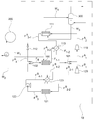
본 출원의 열 회수 장치(10)의 또 하나의 구현예는, 제 1 열교환기(113)를 포함한다. 도 3은, 본 출원의 또 하나의 구현예에 의한 열 회수 장치(10)를 모식적으로 나타낸 도면이다.Another embodiment of the
도 3에 나타나듯이, 본 출원의 열 회수 장치(10)는 상기 증발기(100)와 유체 분배기(101) 사이 및 제 1 응축기(111) 및 압력 강하 장치(112) 사이에 위치하는 제 1 열교환기(113)를 추가로 포함한다. 예를 들어, 상기 제 1 열교환기(113)는 상기 증발기(100)와 유체 분배기(101) 사이에 연결된 배관 및 제 1 응축기(111) 및 압력 강하 장치(112) 사이에 연결된 배관에 연결되어 있을 수 있으며, 하나의 예시에서, 상기 제 1 열교환기(113)는, 증발기(100)에서 유출되는 냉매 흐름(F1-1)이 상기 제 1 열교환기(113)를 통과한 후 제 1 압축기(110)로 유입(FA 1)되고, 제 1 응축기(111)에서 유출되는 냉매 흐름(FA 3 -1)이 상기 제 1 열교환기(113)를 통과한 후 상기 압력 강하 장치(112)로 유입(FA 3 -2)되도록 상기 배관에 유체 연결되어 있을 수 있다. 본 출원의 열 회수 장치(10)가 상기 제 1 열교환기(113)를 포함함으로써, 냉매의 등엔트로피 압축시에 발생하는 냉매의 일부 기화 현상을 막을 수 있으며, 이에 따라, 상기 열 회수 장치(10)의 열교환 효율을 상승시킬 수 있다. 상기에서 「등엔트로피 압축」은 계의 엔트로피를 일정하게 유지하는 조건에서 압축시키는 것을 의미하며, 예를 들어, 계의 주변과 열교환이 없는 상태에서 압축시키는 단열 압축과정을 의미할 수 있다.3, the
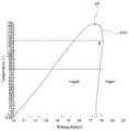
도 4는, 본 출원의 예시적인 냉매의 온도-엔트로피 선도를 도시한 그래프이다. 하나의 예시에서, 상기 열 회수 장치(10)를 순환하는 상기 냉매는, 도 4에 나타나듯이, 온도-엔트로피 선도의 포화증기곡선(saturated vapor curve)의 접선의 기울기가 양의 기울기를 가지는 냉매일 수 있으며, 예를 들어, 가로축은 엔트로피(J/kg·K), 세로축은 온도(℃)인 상기 냉매의 온도-엔트로피 선도의 포화증기곡선의 접선의 기울기는 50℃ 내지 130℃에서 1 내지 3일 수 있다. 상기 온도-엔트로피 선도에서 포화증기곡선은 선도의 임계점(critical point)을 기준으로 하여 선도 우측의 곡선 부분을 의미한다. 즉, 도 4에 나타나 듯이, 냉매의 온도-엔트로피 선도에서, 상기 냉매가 등-엔트로피 압축될 경우(도 4의 화살표 방향), 상기 냉매의 포화증기곡선의 접선의 기울기가 양의 기울기를 가지므로 기상에서 액상으로 상변화가 발생하는 구간이 존재하게 되며, 이에 따라, 제 1 압축기(110) 내에서 냉매 흐름의 일부가 기화되는 현상이 발생할 수 있다. 상기 냉매의 일부 기화 현상을 방지하기 위하여, 본 출원의 열 회수 장치(10)는 상기 제 1 열교환기(113)를 포함할 수 있으며, 이에 따라, 상기 열 회수 장치(10)의 열교환 효율을 상승시킬 수 있다. 4 is a graph showing an exemplary temperature-entropy diagram of the refrigerant of the present application. In one example, as shown in FIG. 4, the refrigerant circulating in the
상기 냉매로는, 온도-엔트로피 선도의 포화증기곡선의 접선의 기울기가 양의 값을 가지는 냉매라면, 기술 분야에서 공지된 다양한 냉매를 사용할 수 있으나, 특별히 제한되는 것은 아니며, 예를 들어, R245fa, R1234ze 및 R1234yf로 이루어진 군으로부터 선택된 1종 이상의 냉매를 사용할 수 있다.As the refrigerant, various refrigerants known in the art may be used, provided that the slope of the tangent of the saturated vapor curve of the temperature-entropy curve has a positive value. However, the refrigerant is not particularly limited and includes, for example, R245fa, R1234ze and R1234yf may be used as the refrigerant.
도 3과 같이, 본 출원의 구현예에 따른 열 회수 장치(10)의 제 1 순환 루프(R1)에서는, 상기 증발기(100)에서 유출되는 냉매 흐름(F1-1)은 상기 제 1 열교환기(113)로 유입된 후에, 상기 제 1 압축기로 유입(FA 1)되고, 상기 제 1 응축기(111)에서 유출되는 냉매 흐름(FA 3 -1)은 상기 제 1 열교환기(113)로 유입된 후에 상기 압력 강하 장치(112)로 유입(FA 3 -2)되며, 상기 증발기(100)에서 유출되는 냉매 흐름(F1-1)과 상기 제 1 응축기(111)에서 유출되는 냉매 흐름(FA 3 -1)은 상기 제 1 열교환기(113)에서 열교환될 수 있다.3, in the first circulation loop R 1 of the
하나의 예시에서, 상기 제 1 응축기(111)에서 유출되어 제 1 열교환기(113)로 유입되는 냉매 흐름(FA 3 -1)의 온도와 제 1 열교환기(113)에서 유출되어 상기 유체 분배기(101)로 유입되는 냉매 흐름(F1-2)의 온도가 하기 일반식 6을 만족할 수 있다.In one example, the temperature of the refrigerant flow (F A 3 -1 ) flowing out of the
[일반식 6][Formula 6]
1℃ ≤ TR1in - TR1out ≤ 50℃1 ° C ≤ T R1in - T R1out ≤ 50 ° C
상기 일반식 6에서, TR1in은 제 1 응축기(111)에서 유출되어 제 1 열교환기(113)로 유입되는 냉매 흐름(FA 3 -1)의 온도를 나타내고, TR1out은 상기 제 1 열교환기(113)에서 유출되어 상기 유체 분배기(101)로 유입되는 냉매 흐름(F1-2)의 온도를 나타낸다.T R1in represents the temperature of the refrigerant flow (F A 3 -1 ) flowing out from the
즉, 상기 제 1 응축기(111)에서 유출되어 제 1 열교환기(113)로 유입되는 냉매 흐름(FA 3-1)의 온도와 제 1 열교환기(113)에서 유출되어 상기 유체 분배기(101)로 유입되는 냉매 흐름(F1-2)의 온도의 차 TR3in - TR3out은 1 내지 50℃, 예를 들어, 5 내지 45℃, 5 내지 50℃, 10 내지 45℃, 1 내지 40℃ 또는 15 내지 35℃의 범위로 조절될 수 있다. That is, the temperature of the refrigerant flow F A 3-1 flowing out from the
상기 제 1 응축기(111)에서 유출되어 제 1 열교환기(113)로 유입되는 냉매 흐름(FA 3 -1)의 온도와 제 1 열교환기(113)에서 유출되어 상기 유체 분배기(101)로 유입되는 냉매 흐름(F1-2)의 온도가 상기 일반식 6을 만족함으로써, 전술한 냉매의 일부 기화 현상을 막을 수 있을 정도로 상기 제 1 압축기(110)로 유입되는 냉매 흐름의 온도를 충분히 상승시킬 수 있으며, 이에 따라, 상기 열 회수 장치(10)의 열교환 효율을 상승시킬 수 있다. The temperature of the refrigerant flow F A 3 -1 flowing out of the
상기 제 1 응축기(111)에서 유출되어 제 1 열교환기(113)로 유입되는 냉매 흐름(FA 3 -1)의 온도와 제 1 열교환기(113)에서 유출되어 상기 유체 분배기(101)로 유입되는 냉매 흐름(F1-2)의 온도는 상기 일반식 6을 만족한다면, 특별히 제한되는 것은 아니며, 적용하고자 하는 공정의 종류 및 각 공정의 조건에 따라 다양하게 조절할 수 있다. 하나의 예시에서, 상기 제 1 응축기(111)에서 유출되어 상기 제 1 열교환기(113)로 유입되는 냉매 흐름(FA 3 -1)의 온도는, 115℃ 내지 150℃, 예를 들어, 118℃ 내지 145℃, 120℃ 내지 148℃ 또는 120℃ 내지 145℃일 수 있으나, 특별히 이에 제한되는 것은 아니다. 또한, 상기 제 1 열교환기(113)에서 유출되어 유체 분배기(101)로 유입되는 냉매 흐름(F1-2)은 90℃ 내지 150℃, 예를 들어, 90℃ 내지 130℃, 90℃ 내지 120℃, 100℃ 내지 130℃ 또는 90℃ 내지 128℃의 온도로 상기 유체 분배기(101)로 유입될 수 있다.The temperature of the refrigerant flow F A 3 -1 flowing out of the
하나의 예시에서, 상기 제 1 열교환기(113)에서 유출되어 압력 강하 장치(112)로 유입되는 냉매 흐름(FA 3 -2)의 온도는 70℃ 내지 120℃, 예를 들어, 75℃ 내지 120℃, 또는 80℃ 내지 120℃일 수 있으나, 특별히 이에 제한되는 것은 아니며, 상기 제 1 압축기(110)에서 유출되는 냉매 흐름(FA 2)은, 110℃ 내지 170℃, 예를 들어, 130℃ 내지 150℃, 135℃ 내지 170℃ 또는 135℃ 내지 165℃의 온도로 상기 제 1 압축기(110)에서 유출되어 상기 제 1 응축기(111)로 유입될 수 있으나, 이에 제한되는 것은 아니다.In one example, the first outlet is in the
본 출원의 열 회수 장치(10)가 상기 제 1 열교환기(113)를 포함함에 따라, 상기 제 1 압축기(110) 내에서의 냉매의 일부 기화 현상을 막을 수 있다. 이 경우, 상기 제 1 압축기(110)에서 유출되는 냉매 흐름(FA 2)은 기상의 흐름일 수 있으며, 상기 제 1 압축기(110)에서 유출되는 냉매 흐름(FA 2) 내의 기상 흐름의 부피 분율은 0.95 내지 1.0, 예를 들어, 0.99 내지 1.0, 바람직하게는 1.0일 수 있다.As the
본 출원의 열 회수 장치(10)의 또 하나의 구현예는, 제 2 열교환기(123)를 포함한다. 도 5는, 본 출원의 또 하나의 구현예에 의한 열 회수 장치(10)를 모식적으로 나타낸 도면이다.Another embodiment of the
도 5에 나타나듯이, 본 출원의 열 회수 장치(10)는 상기 터빈(120)과 제 2 응축기(121) 사이 및 제 2 압축기(122) 및 유체 혼합기(102) 사이에 위치하는 제 2 열교환기(123)를 추가로 포함한다. 예를 들어, 상기 제 2 열교환기(123)는 상기 터빈(120)과 제 2 응축기(121) 사이에 연결된 배관 및 제 2 압축기(122) 및 유체 혼합기(102) 사이에 연결된 배관에 연결되어 있을 수 있으며, 하나의 예시에서, 상기 제 2 열교환기(123)는, 터빈(120)에서 유출되는 냉매 흐름(FB 2 -1)이 상기 제 2 열교환기(123)를 통과한 후 제 2 응축기(121)로 유입(FB 2-2)되고, 제 2 압축기(122)에서 유출되는 냉매 흐름(FB 4 -1)이 상기 제 2 열교환기(123)를 통과한 후 상기 유체 혼합기(102)로 유입(FB 4 -2)되도록 상기 배관에 유체 연결되어 있을 수 있다. 5, the
하나의 예시에서, 상기 터빈(120)에서 유출되는 냉매 흐름(FB 2 -1)은 90℃ 내지 120℃, 예를 들어, 90℃ 내지 115℃ 또는 95℃ 내지 112℃의 온도로 제 2 열교환기(123)로 유입될 수 있으며, 상기 터빈에서 유출되는 냉매 흐름(FB 2 -1)은 상기 제 2 열교환기(123)를 통과한 후에 50℃ 내지 75℃, 예를 들어, 55℃ 내지 70℃ 또는 50℃ 내지 70℃의 온도로 제 2 응축기(121)로 유입(FB 2-2)될 수 있으나, 이에 제한되는 것은 아니다.In one example, the refrigerant stream (F B 2 -1 ) flowing out of the
하나의 예시에서, 상기 제 2 응축기(121)에서 유출되는 냉매 흐름(FB 3)은 30℃ 내지 50℃, 예를 들어, 35℃ 내지 45℃ 또는 35℃ 내지 40℃의 온도로 제 2 압축기(122)로 유입될 수 있으나, 이에 제한되는 것은 아니다.In one example, the refrigerant flow (F B 3 ) flowing out of the
또한, 상기 제 2 압축기(122)에서 유출되는 냉매 흐름(FB 4 -1)은 30℃ 내지 50℃, 예를 들어, 35℃ 내지 45℃ 또는 35℃ 내지 40℃의 온도로 제 2 열교환기(123)로 유입(FB 4 -1)될 수 있으며, 상기 제 2 압축기(122)에서 유출되는 냉매 흐름(FB 4 -1)은 제 2 열교환기(123)를 통과한 후에 40℃ 내지 70℃, 예를 들어, 45℃ 내지 65℃ 또는 40℃ 내지 65℃의 온도로 유체 혼합기(102)로 유입된 후에 증발기(100)로 유입(FB 4 -2)될 수 있으나, 이에 제한되는 것은 아니다.Also, the refrigerant flow (F B 4 -1 ) flowing out of the second compressor (122) is cooled to a temperature of 30 ° C to 50 ° C, for example, 35 ° C to 45 ° C or 35 ° C to 40 ° C, (F B 4 -1 ) flowing into the
본 출원의 열 회수 장치(10)의 또 하나의 구현예는, 도 6과 같이, 제 1 열교환기(113) 및 제 2 열교환기(123)를 모두 포함할 수 있으며, 이에 따른 효과는 전술한 바와 동일하다. 도 6은, 본 출원의 또 하나의 구현예에 의한 열 회수 장치(10)를 모식적으로 나타낸 도면이다.Another embodiment of the
본 출원의 또 다른 구현예는, 열 회수 방법을 제공한다. 예시적인 상기 열 회수 방법은, 전술한 열 회수 장치(10)를 사용하여, 수행될 수 있으며, 이를 통하여, 전술한 바와 같이, 산업 현장 또는 다양한 화학 공정, 예를 들면 석유 화학 제품의 제조 공정에서 배출되는 100℃ 미만의 저급 열원을 버리지 않고 이용하여 스팀을 생성할 수 있으며, 생성된 스팀을 다양한 공정에 사용할 수 있으므로, 반응기 또는 증류탑에 사용되기 위한 외부 열원인 고온 스팀의 사용량을 절감할 수 있어, 에너지 절감 효율을 극대화 시킬 수 있다. 나아가, 본 출원의 열 회수 방법에 의하면, 압축기에서 소모되는 전력을 자체적으로 생산할 수 있으며, 압축기를 통과한 냉매 흐름의 일부 기화 현상을 감소시킬 수 있으므로, 우수한 효율로 열을 회수할 수 있다.Another embodiment of the present application provides a heat recovery method. The exemplary heat recovery method can be performed using the above-described
본 출원의 일 구현예에 의한 상기 열 회수 방법은 냉매 순환 단계, 제 1 열교환 단계 및 제 2 열교환 단계를 포함한다.The heat recovery method according to an embodiment of the present application includes a refrigerant circulation step, a first heat exchange step and a second heat exchange step.
상기 냉매 순환 단계는, 제 1 순환 단계 및 제 2 순환 단계를 포함하며, 상기 제 1 순환 단계는 상술한 제 1 순환 루프(R1)를 통해 냉매가 순환하는 단계이고, 상기 제 2 순환 단계는 상기 제 2 순환 루프(R2)를 통하여 냉매가 순환하는 단계일 수 있다. Wherein the refrigerant circulation step includes a first circulation step and a second circulation step, wherein the first circulation step is a step of circulating the refrigerant through the first circulation loop (R 1 ) described above, and the second circulation step And the refrigerant circulates through the second circulation loop R 2 .
하나의 예시에서, 상기 제 1 순환 단계에서는, 냉매 흐름을 증발기(100), 제 1 압축기(110), 제 1 응축기(111) 및 압력 강하 장치(112)를 순차로 통과하도록 순환시키며, 예를 들어, 상기 제 1 순환 단계에서는, (a-i) 냉매 흐름을 증발기(100)로 유입시키고, (a-ii) 상기 증발기(100)에서 유출되는 냉매 흐름(F1)의 일부를 제 1 압축기(110)로 유입시키며, (a-iii) 상기 제 1 압축기(110)에서 유출되는 냉매 흐름(FA 2)을 제 1 응축기(111)로 유입시키고, (a-iv) 상기 제 1 응축기(111)에서 유출되는 냉매 흐름(FA 3)을 압력 강하 장치(112)로 유입시키며, (a-v) 상기 압력 강하 장치에서 유출되는 냉매 흐름(FA 4)을 상기 증발기(100)로 재유입 시킬 수 있다. In one example, in the first circulation step, the refrigerant flow is circulated through the
또한, 상기 제 2 순환 단계에서는, 냉매 흐름을 증발기(100), 터빈(120), 제 2 응축기(121) 및 제 2 압축기(122)를 순차로 통과하도록 순환시키며, 예를 들어, 상기 제 2 순환 단계에서는, (b-i) 상기 증발기(100)에서 유출되는 냉매 흐름(F1)의 나머지 일부를 터빈(120)으로 유입시키고, (b-ii) 상기 터빈(120)에서 유출되는 냉매 흐름(FB 2)을 제 2 응축기(121)로 유입시키며, (b-iii) 상기 제 2 응축기(121)에서 유출되는 냉매 흐름(FB 3)을 제 2 압축기(122)로 유입시키고, (b-iv) 상기 제 2 압축기(122)에서 유출되는 냉매 흐름(FB 4)을 상기 증발기(100)로 재유입 시킬 수 있다.In the second circulation step, the refrigerant circulates through the
또한, 상기 열 회수 방법은, 상기 증발기(100)로 유입되는 냉매 흐름(F5)을 상기 증발기(100)로 유입되는 제 1 유체 흐름(W1)과 열교환시는 제 1 열교환 단계 및 상기 제 1 압축기에서 유출되는 냉매 흐름(FA 2)을 상기 제 1 응축기로 유입되는 제 2 유체 흐름(W3)과 열교환시키는 제 2 열교환 단계를 포함한다.The heat recovery method may further include a first heat exchange step of exchanging a refrigerant flow F 5 flowing into the
상기 냉매 순환 단계, 제 1 열교환 단계 및 제 2 열교환 단계는 순차적으로 이루어지거나, 또는 순서에 관계없이 서로 독립적으로 이루어질 수 있다. 또한, 상기 제 1 순환 단계의 (a-i) 내지 (a-v)의 과정 및 제 2 순환 단계의 (b-i) 내지 (b-iv)의 과정은 순환 과정이므로, 상기와 같이 냉매 흐름이 순환될 수만 있다면, 어느 과정이 먼저 수행되더라도 무방하다.The refrigerant circulation step, the first heat exchanging step, and the second heat exchanging step may be performed sequentially, or independently of each other. Also, since the processes of (ai) to (av) of the first circulation step and the processes of (bi) to (b-iv) of the second circulation step are a circulation process, if the refrigerant flow can be circulated as described above, Any process may be performed first.
하나의 예시에서, 상기 증발기(100)에서 유출되는 냉매 흐름(F1)의 전체 유량에 대한 제 1 압축기(110)로 유입되는 냉매 흐름(FA 1)의 유량의 비는 하기 일반식 1을 만족할 수 있다.In one example, the ratio of the flow rate of the refrigerant flow (F A 1 ) flowing into the first compressor (110) to the total flow rate of the refrigerant flow (F 1 ) flowing out of the evaporator (100) Can be satisfied.
[일반식 1][Formula 1]
0.3 ≤ Fc/Fe ≤ 0.5 0.3 ≤ F c / F e ≤ 0.5
상기 일반식 1에서, Fc는 제 1 압축기(110)로 유입되는 냉매 흐름(FA 1)의 유량을 나타내고, Fe는 증발기(100)에서 유출되는 냉매 흐름(F1)의 전체 유량을 나타낸다.F c represents the flow rate of the refrigerant flow F A 1 flowing into the
또한, 하나의 예시에서, 상기 증발기(100)에서 유출되는 냉매 흐름(F1)의 전체 유량에 대한 상기 터빈(120)으로 유입되는 냉매 흐름(FB 1)의 유량의 비는 하기 일반식 2를 만족할 수 있다.In one example, the ratio of the flow rate of the refrigerant flow F B 1 flowing into the
[일반식 2][Formula 2]
0.5 ≤ Ft/Fe ≤ 0.70.5? Ft / Fe ? 0.7
상기 일반식 2에서, Ft는 유체 분배기(101)에서 분리되어 터빈(120)으로 유입되는 냉매 흐름(FB 1)의 유량을 나타내고, Fe는 증발기(100)에서 유출되는 냉매 흐름(F1)의 전체 유량을 나타낸다.Where F t represents the flow rate of the refrigerant flow F B 1 separated from the
상기 증발기(100)에서 유출되는 냉매 흐름(F1)의 전체 유량에 대한 상기 제 1 압축기(110)로 유입되는 냉매 흐름(FA 1)의 유량의 비가 상기 일반식 1을 만족하고 상기 증발기(100)에서 유출되는 냉매 흐름(F1)의 전체 유량에 대한 상기 터빈(120)으로 유입되는 냉매 흐름(FB 1)의 유량의 비가 상기 일반식 2를 만족함으로써, 본 출원의 열 회수 장치(10)가 1 기의 증발기만을 사용하는 경우에도, 상기 열 회수 장치가 우수한 성능 계수를 가질 수 있다.The ratio of the flow rate of the refrigerant flow F A 1 flowing into the
또한, 본 출원의 열 회수 방법에서, 상기 증발기(100)에서 유출되는 냉매 흐름의 전체 유량, 상기 제 1 압축기(110)로 유입되는 냉매 흐름(FA 1)의 유량, 상기 터빈(120)으로 유입되는 냉매 흐름(FB 1)의 유량 조건에 대한 자세한 설명은 상기 열 회수 장치(10)에서 전술한 바와 동일한 바, 생략하기로 한다.In the heat recovery method of the present application, the total flow rate of the refrigerant flowing out of the
예시적인 본 출원의 열 회수 방법에서, 상기 증발기(100)에서 유출되는 냉매 흐름(F1)의 온도와 상기 증발기(100)로 유입되는 제 1 유체 흐름(W1)의 온도는 하기 일반식 3을 만족할 수 있다.The temperature of the refrigerant flow F 1 flowing out of the
[일반식 3][Formula 3]
1℃ ≤ TEin - TEout ≤ 20℃1 ° C ≤ T Ein - T Eout ≤ 20 ° C
상기 일반식 3에서, TEin는 증발기(100)로 유입되는 제 1 유체 흐름(W1)의 온도를 나타내고, TEout은 상기 증발기(100)에서 유출되는 냉매 흐름(F1)의 온도를 나타낸다.T Ein represents the temperature of the first fluid flow W 1 flowing into the
상기 증발기(100)에서 유출되는 냉매 흐름(F1)의 온도와 상기 증발기(100)로 유입되는 제 1 유체 흐름(W1)의 온도가 상기 일반식 3을 만족함으로써, 저온의 폐열, 특히, 100℃ 미만, 예를 들어, 50 내지 90℃ 수준의 현열 상태의 저급 열원의 폐열을 이용하여, 고온의 스팀을 생산할 수 있으며, 상기 증발기(100)에서 유출되는 냉매 흐름(F1)의 온도와 상기 증발기(100)로 유입되는 제 1 유체 흐름(W1)의 온도에 관한 자세한 설명은, 전술한 열 회수 장치(10)에서 설명한 바와 동일한 바, 생략하기로 한다.When the temperature of the refrigerant flow F 1 flowing out of the
또한, 본 출원의 열 회수 방법에서는, 상기 제 1 압축기(110)로 유입되는 냉매 흐름(FA 1)의 압력과 제 1 압축기(110)에서 유출되는 냉매 흐름(FA 2)의 압력의 비는 하기 일반식 4를 만족할 수 있다.In the heat recovery method of the present application, the ratio of the pressure of the refrigerant flow (F A 1 ) flowing into the first compressor (110) to the pressure of the refrigerant flow (F A 2 ) flowing out of the first compressor (110) Can satisfy the following general formula (4).
[일반식 4][Formula 4]
2 ≤ PC1out/PCin ≤ 52? P C1out / P Cin ? 5
상기 일반 4에서, PC1out은 상기 제 1 압축기(110)에서 유출되는 냉매 흐름(FA 2)의 압력(bar)을 나타내고, PC1in은 상기 제 1 압축기(110)로 유입되는 냉매 흐름(FA 1)의 압력(bar)을 나타낸다.In the general 4, P C1out represents the pressure (bar) of the refrigerant flow F A 2 flowing out of the
상기 제 1 압축기(110)로 유입되는 냉매 흐름(FA 1)의 압력과 제 1 압축기(110)에서 유출되는 냉매 흐름(FA 2)의 압력의 비가 상기 일반식 4를 만족함으로써, 상기 증발기(100)에서 기화된 냉매는 후술할 제 1 응축기(111)를 통과하는 제 2 유체 흐름(W3)과 열교환되기에 충분한 열량을 가지도록 고온 및 고압 상태로 압축될 수 있으며, 제 1 압축기(111)로 유입되는 냉매 흐름(FA 1)의 압력과 제 1 압축기에서 유출되는 냉매 흐름(FA 2)의 압력 조건에 관한 자세한 설명은, 전술한 열 회수 장치(10)에서 설명한 바와 동일한 바, 생략하기로 한다.The ratio of the pressure of the refrigerant flow F A 1 flowing into the
상기 제 2 응축기(121)에서 유출되어 제 2 압축기(122)로 유입되는 냉매 흐름(FB 3)의 압력과 제 2 압축기(122)에서 유출되는 냉매 흐름(FB 4)의 압력의 비가 하기 일반식 5를 만족할 수 있다.The ratio of the pressure of the refrigerant flow F B 3 flowing out of the
[일반식 5][Formula 5]
2 ≤ PC2out/PC2in ≤ 72? P C2out / P C2in ? 7
상기 일반식 5에서, PC2out는 상기 제 2 압축기(122)에서 유출되는 냉매 흐름(FB 4)의 압력(bar)을 나타내고, PC2in는 제 2 응축기(121)에서 유출되어 제 2 압축기(122)로 유입되는 냉매 흐름(FB 3)의 압력(bar)을 나타낸다. In
상기 제 2 응축기(121)에서 유출되어 제 2 압축기(122)로 유입되는 냉매 흐름(FB 3)의 압력과 제 2 압축기(122)에서 유출되는 냉매 흐름(FB 4)의 압력의 비가 상기 일반식 5를 만족함으로써, 상기 터빈(120)에서 전기를 발생시키고 떨어진 압력을 보충하기에 충분할 정도로 압축될 수 있으며, 상기 제 2 응축기(121)에서 유출되어 제 2 압축기(122)로 유입되는 냉매 흐름(FB 3)의 압력과 제 2 압축기(122)에서 유출되는 냉매 흐름(FB 4)의 압력 조건에 관한 자세한 설명은, 전술한 열 회수 장치(10)에서 설명한 바와 동일한 바, 생략하기로 한다.The ratio of the pressure of the refrigerant flow F B 3 flowing out of the
또한, 본 출원의 열 회수 방법에서, 구체적인 온도, 압력 및 유량 조건은 상기 열 회수 장치(10)에서 전술한 바와 동일한 바, 생략하기로 한다.In the heat recovery method of the present application, the specific temperature, pressure, and flow rate conditions are the same as those described above in the
본 출원의 열 회수 방법의 또 다른 구현예에서, 상기 냉매 순환 단계의 제 1 순환 단계 및 제 2 순환 단계에서 상기 냉매는, 전술한 바와 같이, 온도-엔트로피 선도의 포화증기곡선의 접선의 기울기가 양의 기울기를 가지는 냉매일 수 있으며, 예를 들어, 가로축은 엔트로피(J/kg·K), 세로축은 온도(℃)인 상기 온도-엔트로피 선도의 포화증기곡선의 접선의 기울기는 50℃ 내지 130℃에서 1 내지 3일 수 있다. 또한, 이 경우, 상기 제 1 순환 단계는, 상기 증발기(100)에서 유출되는 냉매 흐름(F1-1)을 제 1 열교환기(113)로 유입시킨 후에 제 1 압축기(110)로 유입(FA 1)시키고, 제 1 응축기(111)에서 유출되는 냉매 흐름(FA 3 -1)을 제 1 열교환기(113)로 유입시킨 후에 압력 강하 장치(112)로 유입(FA 3 -2)시키는 것을 추가로 포함할 수 있다.In another embodiment of the heat recovery method of the present application, in the first circulation step and the second circulation step of the refrigerant circulation step, as described above, the slope of the tangent of the saturated vapor curve of the temperature-entropy line is The slope of the tangent line of the saturated vapor curve of the temperature-entropy curve having the entropy (J / kg · K) and the vertical axis of the temperature (° C.) may be 50 ° C. to 130 ° C. RTI ID = 0.0 > 1 C < / RTI > In this case, in the first circulation step, the refrigerant flow (F 1-1 ) flowing out of the
이와 같은 경우, 본 출원의 또 하나의 구현예의 열 회수 방법은, 증발기(100)에서 유출되는 냉매 흐름(F1-1)과 상기 제 1 응축기(111)에서 유출되는 냉매 흐름(FA 3 -1)을 제 1 열교환기(113)에서 열교환시키는 제 3 열교환 단계를 추가로 포함할 수 있다. 상기 제 3 열교환 단계는 전술한 열 교환 장치(10)의 제 1 열교환기(113)를 통하여 이루어질 수 있으며, 이에 따라, 전술한 바와 같이, 냉매의 등엔트로피 압축시에 발생하는 냉매의 일부 기화 현상을 막을 수 있으며, 상기 열 회수 장치(10)의 열교환 효율을 상승시킬 수 있다. In this case, the heat recovery method of another embodiment of the present application is characterized in that the refrigerant flow (F 1-1 ) flowing out of the evaporator (100) and the refrigerant flow (F A 3 - 1 ) in the first heat exchanger (113) may be further included. The third heat exchanging step may be performed through the
하나의 예시에서, 상기 제 1 응축기(111)에서 유출되어 제 1 열교환기(113)로 유입되는 냉매 흐름(FA 3 -1)의 온도와 제 1 열교환기(113)에서 유출되어 상기 유체 분배기(101)로 유입되는 냉매 흐름(F1-2)의 온도는 하기 일반식 6을 만족할 수 있다.In one example, the temperature of the refrigerant flow (F A 3 -1 ) flowing out of the
[일반식 6][Formula 6]
5℃ ≤ TR1in - TR1out ≤ 20℃5 ° C ≤ T R1in - T R1out ≤ 20 ° C
상기 일반식 6에서, TR1in은 제 1 응축기(111)에서 유출되어 제 1 열교환기(113)로 유입되는 냉매 흐름(FA 3 -1)의 온도를 나타내고, TR1out은 상기 제 1 열교환기(113)에서 유출되어 상기 유체 분배기(101)로 유입되는 냉매 흐름(F1-2)의 온도를 나타낸다.T R1in represents the temperature of the refrigerant flow (F A 3 -1 ) flowing out from the
상기 제 1 응축기(111)에서 유출되어 제 1 열교환기(113)로 유입되는 냉매 흐름(FA 3 -1)의 온도와 제 1 열교환기(113)에서 유출되어 상기 유체 분배기(101)로 유입되는 냉매 흐름(F1-2)의 온도가 상기 일반식 6을 만족함으로써, 전술한 냉매의 일부 기화 현상을 막을 수 있을 정도로 상기 제 1 압축기(110)로 유입되는 냉매 흐름(FA 1)의 온도를 충분히 상승시킬 수 있으며, 이에 따라, 상기 열 회수 장치(10)의 열교환 효율을 상승시킬 수 있다. The temperature of the refrigerant flow F A 3 -1 flowing out of the
상기 제 3 열교환 단계에서, 냉매 흐름의 구체적인 온도, 압력 및 유량 조건은 상기 열 회수 장치(10)에서 전술한 바와 동일한 바, 생략하기로 한다. In the third heat exchanging step, the specific temperature, pressure, and flow rate conditions of the refrigerant flow are the same as those described above in the
본 출원의 열 회수 방법의 또 하나의 구현예에서, 상기 제 2 순환 단계는, 터빈(120)에서 유출되는 냉매 흐름(FB 2 -1)을 제 2 열교환기(123)로 유입시킨 후에 제 2 응축기(121)로 유입(FB 2 -2)시키고, 제 2 압축기(122)에서 유출되는 냉매 흐름(FB 4 -1)을 제 2 열교환기(123)로 유입시킨 후에 증발기(100)로 유입(FB 4 -2)시키는 것을 추가로 포함할 수 있다.In another embodiment of the heat recovery method of the present application, the second circulation step may include introducing the refrigerant flow (F B 2 -1 ) flowing out of the
또한, 이와 같은 경우, 상기 열 회수 방법은, 상기 터빈(120)에서 유출되는 냉매 흐름(FB 2-1)과 상기 제 2 압축기(122)에서 유출되는 냉매 흐름(FB 4 -1)을 상기 제 2 열교환기(123)에서 열교환시키는 제 4 열교환 단계를 추가로 포함할 수 있다.In this case, the heat recovery method may further include a step of supplying the refrigerant flow F B 2-1 flowing out of the
상기 제 4 열교환 단계는 전술한 열 교환 장치(10)의 제 2 열교환기(123)를 통하여 이루어질 수 있으며, 상기 제 4 열교환 단계에서, 냉매 흐름의 구체적인 온도, 압력 및 유량 조건은 상기 열 회수 장치(10)에서 전술한 바와 동일한 바, 생략하기로 한다.The fourth heat exchanging step may be performed through the
상기 열 회수 방법의 또 다른 구현예에서, 상기 제 1 응축기(111)로 유입되는 제 2 유체(W3)는 물일 수 있으며, 또한, 예시적인 본 출원의 열 회수 방법은 상기 제 1 응축기(111)로 유입되는 냉매 흐름과 열교환된 물을 스팀으로 배출시키는 스팀 생성 단계를 추가로 포함할 수 있다In another embodiment of the heat recovery method, the second fluid (W 3 ) entering the
또한, 상기 열 회수 방법의 다른 구현예는, 상기 증발기(100)에서 유출되는 유체 흐름을 응축시켜 배출하는 단계를 추가로 포함할 수 있다.In addition, another embodiment of the heat recovery method may further include a step of condensing and discharging the fluid flowing out from the
본 출원의 열 회수 장치(10) 및 방법은 다양한 석유 화학 공정에 적용될 수 있다. The
예를 들어, n-부탄올 제조 시 옥소 반응 공정의 경우, 공정에서 발생하는 폐열의 온도는 약 85℃로, 이 경우, 약 7.6 Gcal/hr의 열량이 버려지므로, 상기 옥소 반응 공정에 적용될 수 있다. 또한, 알킬레이션 반응을 통한 큐멘의 제조 공정의 경우 약 6.8 Gcal/hr의 열량이 버려지고 있어, 상기 큐멘의 제조 공정에도 적용이 가능하다. 또한, 아크릴산의 제조 공정 시, 흡수기에서 발생하는 폐열의 온도는 약 75℃로, 이 경우, 약 1.6 내지 3.4 Gcal/hr의 열량이 버려지고 있어, 상기 아크릴산의 제조 공정에도 적용이 가능하다. For example, in the case of the oxo reaction process in the production of n-butanol, the temperature of the waste heat generated in the process is about 85 ° C, in which case the amount of heat of about 7.6 Gcal / hr is discarded, . In addition, in the process of producing cumene by the alkylation reaction, the amount of heat of about 6.8 Gcal / hr is abandoned, and the present invention can be applied to the production process of the cumene. Further, in the production process of acrylic acid, the temperature of the waste heat generated in the absorber is about 75 DEG C, and in this case, the amount of heat of about 1.6 to 3.4 Gcal / hr is abandoned, which is also applicable to the acrylic acid production process.
본 출원의 열 회수 장치 및 방법에 의하면, 산업 현장 또는 다양한 화학 공정, 예를 들면 석유 화학 제품의 제조 공정에서 배출되는 100℃ 미만의 저급 열원을 버리지 않고 이용하여 스팀을 생성할 수 있으며, 생성된 스팀을 다양한 공정에 사용할 수 있으므로, 반응기 또는 증류탑에 사용되기 위한 외부 열원인 고온 스팀의 사용량을 절감할 수 있어, 에너지 절감 효율을 극대화시킬 수 있을 뿐만 아니라, 압축기에서 소모되는 전력을 자체적으로 생산할 수 있으며, 압축기를 통과한 냉매 흐름의 일부 기화 현상을 감소시킬 수 있으므로, 우수한 효율로 열을 회수할 수 있다.According to the heat recovery apparatus and method of the present application, it is possible to generate steam by using a low-temperature heat source of less than 100 ° C discharged from an industrial site or various chemical processes, for example, a production process of a petrochemical product, Since the steam can be used in various processes, it is possible to reduce the amount of high temperature steam used as an external heat source for use in a reactor or a distillation column, thereby maximizing the energy saving efficiency, And it is possible to reduce the partial vaporization phenomenon of the refrigerant flow passing through the compressor, so that heat can be recovered with excellent efficiency.
도 1은 종래의 폐열 처리 장치를 모식적으로 나타낸 도면이다.
도 2는 본 출원의 일 구현예의 열 회수 장치를 모식적으로 도시한 도면이다.
도 3은 본 출원의 다른 구현예에 의한 열 회수 장치를 모식적으로 도시한 도면이다.
도 4는 본 출원의 냉매의 온도-엔트로피 선도를 예시적으로 나타낸 그래프이다.
도 5는 본 출원의 또 다른 구현예에 따른 열 회수 장치를 모식적으로 나타낸 도면이다.
도 6은, 본 출원의 또 하나의 구현예에 의한 열 회수 장치를 모식적으로 나타낸 도면이다.
도 7은 본 출원의 실시예에 따른 열 회수 장치를 나타낸 도면이다. 1 is a view schematically showing a conventional waste heat treatment apparatus.
2 is a diagram schematically showing a heat recovery apparatus of an embodiment of the present application.
3 is a diagram schematically showing a heat recovery apparatus according to another embodiment of the present application.
4 is a graph exemplarily showing the temperature-entropy diagram of the refrigerant of the present application.
5 is a diagram schematically showing a heat recovery apparatus according to another embodiment of the present application.
6 is a diagram schematically showing a heat recovery apparatus according to another embodiment of the present application.
7 is a view showing a heat recovery apparatus according to an embodiment of the present application.
이하 본 출원에 따르는 실시예 및 본 출원에 따르지 않는 비교예를 통하여 본 출원을 보다 상세히 설명하나, 본 출원의 범위가 하기 제시된 실시예에 의해 제한되는 것은 아니다.Hereinafter, the present application will be described in more detail by way of examples according to the present application and comparative examples not complying with the present application, but the scope of the present application is not limited by the following embodiments.
실시예Example 1 One
도 5의 열 회수 장치를 이용하여, 스팀을 생성하였다. Using the heat recovery apparatus of Fig. 5, steam was generated.
냉매(1,1,1,3,3-pentafluoropropane, R245fa)를 증발기로 유입시키고, 상기 증발기에서 분리된 냉매 흐름의 일부를 콤프레셔, 제 1 응축기 및 압력 강하 장치를 순차로 통과하도록, 상기 냉매를 순환시켰다. 구체적으로는, 69.6℃, 6.2 kgf/cm2g(7.1 bar), 기체 부피 분율이 0.0인 상태의 냉매 흐름을 50,000 kg/hr의 유량으로 증발기로 유입시키고, 이와 동시에 상기 증발기로 85.0℃, 1.0 kgf/cm2g(1.96 bar), 기체 부피 분율이 0.0인 상태의 폐열 흐름을 300,000 kg/hr의 유량으로 유입시켜 열교환을 시켰다. 상기 열교환 후 폐열 흐름은 78.2℃, 1.0 kgf/cm2g(1.96 bar), 기체 부피 분율이 0.0인 상태로 300,000 kg/hr의 유량으로 유출시켰으며, 냉매 흐름은 80.0℃, 6.2 kgf/cm2g(7.1 bar), 기체 부피 분율이 1.0인 상태로 유출시킨 후 유체 분배기로 유입하였다. 상기 유체 분배기에서 분리된 냉매 흐름을 19,000 kg/hr의 유량으로 상기 콤프레셔로 유입시켰으며, 또한, 상기 콤프레셔에서 압축된 냉매 흐름은 125.0℃, 20.7 kgf/cm2g(21.3 bar), 기체 부피 분율이 0.82인 상태로 콤프레셔에서 유출시켰다. 이 경우, 상기 콤프레셔에서 사용된 일의 양은 135583.0 W이었다. 상기 콤프레셔로부터 유출된 냉매 흐름을 제 1 응축기로 유입시키고, 이와 동시에 상기 제 1 응축기로 115.0℃, 0.7 kgf/cm2g(1.67 bar), 기체 부피 분율이 0.0인 상태의 물을 1,000 kg/hr의 유량으로 유입시켜 상기 냉매 흐름과 열교환을 시켰다. 상기 열교환 후 물은 115.0℃, 0.7 kgf/cm2g(1.67 bar), 기체 부피 분율이 0.75인 상태의 스팀으로 배출되었으며, 냉매 흐름은 응축되어 125.0℃, 20.7 kgf/cm2g(21.3 bar), 기체 부피 분율이 0.0인 상태로 유출시킨 후에 컨트롤 밸브로 유입되었다. 이 때, 상기 제 1 응축기에서 응축된 열량은 463422.8 W이었다. 또한, 상기 컨트롤 밸브를 통과한 냉매 흐름을 75.4℃, 6.2 kgf/cm2g(7.1 bar), 기체 부피 분율이 0.0인 상태로 상기 컨트롤 밸브에서 유출시킨 후 유체 혼합기로 유입시켰다. A refrigerant (1,1,1,3,3-pentafluoropropane, R245fa) is introduced into an evaporator, and a portion of the refrigerant flow separated from the evaporator is sequentially passed through a compressor, a first condenser, and a pressure- Lt; / RTI > Specifically, a refrigerant flow of 69.6 ° C., 6.2 kgf / cm 2 g (7.1 bar) and a gas volume fraction of 0.0 was introduced into the evaporator at a flow rate of 50,000 kg / hr. At the same time, The heat exchange was carried out by introducing waste heat flow at a flow rate of 300,000 kg / hr with a gas volume fraction of 0.0 kgf / cm 2 g (1.96 bar). After the heat exchange, the waste heat was discharged at a flow rate of 300,000 kg / hr at 78.2 ° C., 1.0 kgf / cm 2 g (1.96 bar) and a gas volume fraction of 0.0. The refrigerant flow was 80.0 ° C. and 6.2 kgf / cm 2 g (7.1 bar), the volume fraction of gas was 1.0, and then flowed into the fluid distributor. The refrigerant flow separated from the fluid distributor was introduced into the compressor at a flow rate of 19,000 kg / hr. The refrigerant flow compressed in the compressor was 125.0 ° C, 20.7 kgf / cm 2 g (21.3 bar), the gas volume fraction Was discharged from the compressor in a state of 0.82. In this case, the amount of work used in the compressor was 135583.0 W. At the same time, water having a volume fraction of 0.0.01 kgf / cm 2 g (1.67 bar) and a gas volume fraction of 0.0.03 kgf / cm 2 was introduced into the first condenser at a rate of 1,000 kg / hr And the heat exchange with the refrigerant flow was performed. The water after the heat exchange was discharged into steam at 115.0 ° C., 0.7 kgf / cm 2 g (1.67 bar) and gas volume fraction of 0.75, and the refrigerant flow was condensed to 125.0 ° C., 20.7 kgf / cm 2 g (21.3 bar) , The gas volume fraction was 0.0, and then flowed into the control valve. At this time, the heat amount condensed in the first condenser was 463422.8 W. The refrigerant flow passed through the control valve was flowed out from the control valve at a rate of 6.2 kgf / cm 2 g (7.1 bar) and a gas volume fraction of 0.0, and then introduced into a fluid mixer.
한편, 상기 유체 분배기에서 분리된 나머지 냉매 흐름이 터빈, 제 2 열교환기, 제 2 응축기, 펌프, 상기 제 2 열교환기 및 유체 혼합기를 순차로 통과하도록 순환 시켰다. 구체적으로, 상기 유체 분배기에서 분리된 나머지 냉매 흐름을 31,000 kg/hr의 유량으로 상기 터빈으로 유입시켰으며, 상기 터빈에서 유출되어 상기 제 2 열교환기로 유입된 냉매 흐름을 제 2 응축기로 유입시켰다. 또한, 상기 제 2 응축기에서 유출시킨 냉매 흐름은 펌프로 유입시켰으며, 상기 펌프에서 압축된 냉매 흐름을 다시 제 2 열교환기로 유입시켜, 상기 터빈으로부터 유출되어 제 2 열교환기로 유입되는 냉매 흐름과 열교환시킨 뒤에, 유체 혼합기로 유입시켰다. 구체적으로, 상기 터빈에서 팽창된 냉매 흐름을 63.1℃, 1.5 kgf/cm2g(2.45 bar), 기체 부피 분율이 1.0인 상태로 상기 터빈에서 유출시킨 후 상기 제 2 열교환기로 유입시켰다. 이 경우, 상기 터빈에서 생성된 일의 양은 137713.0 W이었다. 상기 펌프로부터 유출되는 냉매 흐름과 상기 제 2 열교환기에서 열교환된 냉매 흐름은, 51.6℃, 1.5 kgf/cm2g(2.45 bar), 기체 부피 분율이 1.0인 상태로 상기 제 2 열교환기로 부터 유출된 후, 상기 제 2 응축기로 유입되어 응축되었다. 상기 제 2 응축기에서 응축되어 39.6℃, 1.5 kgf/cm2g(2.45 bar), 기체 부피 분율이 0.0인 상태로 유출되는 냉매 흐름은 펌프로 유입시켜 압축시켰다. 상기 펌프를 통과하여 압축된 냉매 흐름을, 40.0℃, 6.2 kgf/cm2g(7.1 bar), 기체 부피 분율이 0.0인 상태로 상기 펌프에서 유출시킨 후, 상기 제 2 열교환기로 유입시켰으며, 상기 터빈으로부터 유출되어 상기 제 2 열교환기로 유입되는 냉매 흐름과 열교환시켰다. 상기 펌프로부터 유출되고, 제 2 열교환기로 유입되어 열교환 된 냉매 흐름은, 46.6℃, 6.2 kgf/cm2g(7.1 bar), 기체 부피 분율이 0.0인 상태로 상기 제 2 열교환기에서 유출시켰으며, 유체 혼합기로 유입시켰다. 상기 펌프로부터 유출된 냉매 흐름과 상기 컨트롤 밸브로부터 유출된 냉매 흐름을 상기 유체 혼합기에서 합류 시킨 후에, 50,000 kg/hr의 유량으로 상기 증발기로 재유입시켰다,Meanwhile, the remaining refrigerant flow separated from the fluid distributor was circulated through the turbine, the second heat exchanger, the second condenser, the pump, the second heat exchanger, and the fluid mixer in sequence. Specifically, the remaining refrigerant flow separated from the fluid distributor is introduced into the turbine at a flow rate of 31,000 kg / hr, and the refrigerant flowing out of the turbine and flowing into the second heat exchanger is introduced into the second condenser. The refrigerant flowed out from the second condenser is introduced into the pump, the refrigerant flow compressed by the pump is introduced into the second heat exchanger, and the refrigerant flowed out from the turbine and heat-exchanged with the refrigerant flowing into the second heat exchanger And then introduced into a fluid mixer. Specifically, the refrigerant flow expanded in the turbine was flowed out from the turbine at 63.1 ° C., 1.5 kgf / cm 2 g (2.45 bar) and a gas volume fraction of 1.0, and then introduced into the second heat exchanger. In this case, the amount of work produced in the turbine was 137713.0 W. The refrigerant flow discharged from the pump and the refrigerant flow exchanged in the second heat exchanger are discharged from the second heat exchanger at 51.6 ° C, 1.5 kgf / cm 2 g (2.45 bar) and a gas volume fraction of 1.0 And thereafter, it was introduced into the second condenser and condensed. The refrigerant flow condensed in the second condenser and flowing out at 39.6 ° C., 1.5 kgf / cm 2 g (2.45 bar) and a gas volume fraction of 0.0 was introduced into the pump and compressed. The refrigerant flow passed through the pump was flowed out from the pump at a temperature of 40.0 ° C., 6.2 kgf / cm 2 g (7.1 bar), a gas volume fraction of 0.0, and then introduced into the second heat exchanger, Exchanged with the refrigerant flow flowing out from the turbine and flowing into the second heat exchanger. The refrigerant flowed out from the pump and flowed into the second heat exchanger and heat-exchanged was discharged from the second heat exchanger in a state of 46.6 ° C., 6.2 kgf / cm 2 g (7.1 bar) and a gas volume fraction of 0.0, Flow mixer. The refrigerant flow out of the pump and the refrigerant flow out of the control valve were combined in the fluid mixer and then re-introduced into the evaporator at a flow rate of 50,000 kg / hr.
이 경우, 열 회수 장치의 성능 계수를 하기 일반식 8에 의하여 계산하였으며, 하기 표 1에 나타내었다. 상기 성능계수는, 상기 압축기에 투입된 에너지 대비 열교환 매체가 흡수한 열량을 나타내며, 즉, 에너지 투입량 대비 회수한 에너지의 비율을 의미한다. 예를 들어, 성능 계수가 3이라면, 투입한 전기의 3배의 열량을 얻은 것을 의미한다.In this case, the coefficient of performance of the heat recovery apparatus was calculated by the following equation (8), and is shown in Table 1 below. The coefficient of performance indicates the amount of heat absorbed by the heat exchange medium with respect to the energy input to the compressor, that is, the ratio of the energy recovered to the amount of energy input. For example, if the coefficient of performance is 3, it means that three times as much heat as the input electricity is obtained.
[일반식 8][Formula 8]
상기 일반식 8에서, Q는 제 1 응축기에 의하여 응축된 열량을 나타내며, W는 콤프레셔가 한 일의 총 양(콤프레셔에서 사용된 일의 양 - 터빈에서 생산된 일의 양)을 나타낸다.In the general formula (8), Q represents the amount of heat condensed by the first condenser, and W represents the total amount of work the compressor has done (the amount of work used in the compressor-the amount of work produced in the turbine).
실시예Example 2 2
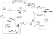
도 7의 열 회수 장치를 이용하여, 스팀을 생성하였다. Using the heat recovery apparatus of Fig. 7, steam was generated.
냉매(1,1,1,3,3-pentafluoropropane, R245fa)를 증발기로 유입시키고, 상기 증발기에서 분리된 냉매 흐름의 일부를 제 1 열교환기, 콤프레셔, 제 1 응축기, 제 1 열교환기 및 압력 강하 장치를 순차로 통과하도록, 상기 냉매를 순환시켰다. 구체적으로는, 69.6℃, 6.2 kgf/cm2g(7.1 bar), 기체 부피 분율이 0.0인 상태의 냉매 흐름을 50,000 kg/hr의 유량으로 증발기로 유입시키고, 이와 동시에 상기 증발기로 85.0℃, 1.0 kgf/cm2g(1.96 bar), 기체 부피 분율이 0.0인 상태의 폐열 흐름을 300,000 kg/hr의 유량으로 유입시켜 열교환을 시켰다. 상기 열교환 후 폐열 흐름은 78.2℃, 1.0 kgf/cm2g(1.96 bar), 기체 부피 분율이 0.0인 상태로 300,000 kg/hr의 유량으로 유출시켰으며, 냉매 흐름은 80.0℃, 6.2 kgf/cm2g(7.1 bar), 기체 부피 분율이 1.0인 상태로 유출시킨 후 제 1 열교환기로 유입시켰다. 상기 증발기에서 유출되어 상기 제 1 열교환기로 유입된 냉매 흐름을 유체 분배기로 유입시켜 일부를 콤프레셔로 유입시켰으며, 상기 콤프레셔에서 유출시킨 냉매 흐름은 제 1 응축기로 유입시켜, 제 1 응축기를 통과하는 유체 흐름과 열교환시켰다. 또한, 상기 제 1 응축기에서 유출시킨 냉매 흐름은 다시 제 1 열교환기로 유입시켜, 상기 증발기로부터 유출되어 상기 제 1 열교환기로 유입되는 냉매 흐름과 열교환시킨 후에, 컨트롤 밸브로 유입시켰다. 구체적으로, 상기 증발기로부터 유출되고, 제 1 열교환기로 유입되어 열교환된 냉매 흐름을 115.0℃, 6.2 kgf/cm2g(7.1 bar), 기체 부피 분율이 1.0인 상태로 상기 제 1 열교환기에서 유출시킨 뒤에 상기 유체 분배기로 유입하였다. 상기 유체 분배기에서 냉매 흐름을 분리한 후에, 분리된 냉매 흐름을 19,000 kg/hr의 유량으로 상기 콤프레셔로 유입시켰으며, 또한, 상기 콤프레셔에서 압축된 냉매 흐름은 142.3℃, 20.6 kgf/cm2g(21.3 bar), 기체 부피 분율이 1.0인 상태로 상기 콤프레셔에서 유출시켰다. 이 경우, 상기 콤프레셔에서 사용된 일의 양은 151682.0 W이었다. 상기 콤프레셔에서 유출된 냉매 흐름을 제 1 응축기로 유입시키고, 이와 동시에 상기 제 1 응축기로 115.0℃, 0.7 kgf/cm2g(1.67 bar), 기체 부피 분율이 0.0인 상태의 물을 1,000 kg/hr의 유량으로 유입시켜 상기 냉매 흐름과 열교환을 시켰다. 상기 열교환 후 물은 120.0℃, 0.7 kgf/cm2g(1.67 bar), 기체 부피 분율이 1.0인 상태의 스팀으로 배출되었으며, 응축된 냉매 흐름을 124.9℃, 20.6 kgf/cm2g(21.3 bar), 기체 부피 분율이 0.08인 상태로 유출시킨 후에 상기 제 1 열교환기로 유입시켰다. 이 때, 상기 제 1 응축기에서 응축된 열량은 620779.0 W이었다. 상기 제 1 응축기에서 유출되는 냉매 흐름은 상기 증발기에서 유출되는 냉매 흐름과 상기 제 1 열교환기에서 열교환 된 후에, 85.3℃, 20.6 kgf/cm2g(21.3 bar), 기체 부피 분율이 0.0인 상태로 상기 제 1 열교환기에서 유출된 후에 컨트롤 밸브로 유입되었다. 또한, 상기 냉매 흐름을 75.4℃, 6.2 kgf/cm2g(7.1 bar), 기체 부피 분율이 0.11인 상태로 상기 컨트롤 밸브에서 유출시킨 후 유체 혼합기로 유입시켰다. A refrigerant (1,1,1,3,3-pentafluoropropane, R245fa) is introduced into an evaporator, and a part of the refrigerant flow separated from the evaporator is introduced into a first heat exchanger, a compressor, a first condenser, a first heat exchanger, The refrigerant was circulated so as to pass through the apparatus in sequence. Specifically, a refrigerant flow of 69.6 ° C., 6.2 kgf / cm 2 g (7.1 bar) and a gas volume fraction of 0.0 was introduced into the evaporator at a flow rate of 50,000 kg / hr. At the same time, The heat exchange was carried out by introducing waste heat flow at a flow rate of 300,000 kg / hr with a gas volume fraction of 0.0 kgf / cm 2 g (1.96 bar). After the heat exchange, the waste heat was discharged at a flow rate of 300,000 kg / hr at 78.2 ° C., 1.0 kgf / cm 2 g (1.96 bar) and a gas volume fraction of 0.0. The refrigerant flow was 80.0 ° C. and 6.2 kgf / cm 2 g (7.1 bar), a gas volume fraction of 1.0, and then introduced into the first heat exchanger. The refrigerant flowing out of the evaporator and flowing into the first heat exchanger is introduced into a fluid distributor to introduce a part of the refrigerant into the compressor. The refrigerant flow out of the compressor flows into the first condenser, Heat exchanged with the flow. Also, the refrigerant flow out of the first condenser flows into the first heat exchanger, exchanges heat with the refrigerant flow flowing out of the evaporator and flowing into the first heat exchanger, and then flows into the control valve. Specifically, the refrigerant flowed out from the evaporator and flowing into the first heat exchanger and heat-exchanged was flowed out from the first heat exchanger at a temperature of 115.0 ° C, 6.2 kgf / cm 2 g (7.1 bar) and a gas volume fraction of 1.0 And then flowed into the fluid distributor. After separating the refrigerant flow from the fluid distributor, the separated refrigerant flow was introduced into the compressor at a flow rate of 19,000 kg / hr, and the refrigerant flow compressed in the compressor was 142.3 ° C, 20.6 kgf / cm 2 g 21.3 bar), and discharged from the compressor with a gas volume fraction of 1.0. In this case, the amount of work used in the compressor was 151682.0 W. And introducing a flow of the refrigerant outlet from the compressor to the first condenser, and at the same time to 115.0 ℃, 0.7 kgf / cm 2 g (1.67 bar), the state gas volume fraction is 0.0, the water in the first condenser, 1,000 kg / hr And the heat exchange with the refrigerant flow was performed. The water after the heat exchange was discharged into steam at 120.0 ° C., 0.7 kgf / cm 2 g (1.67 bar) and gas volume fraction of 1.0, and the condensed refrigerant flow was adjusted to 124.9 ° C. and 20.6 kgf / cm 2 g (21.3 bar) , The gas volume fraction was 0.08, and then flowed into the first heat exchanger. At this time, the heat amount condensed in the first condenser was 620779.0 W. The refrigerant flowing out of the first condenser is heat exchanged in the first heat exchanger with the refrigerant flowing out of the evaporator, and then the refrigerant flows at 85.3 ° C, 20.6 kgf / cm 2 g (21.3 bar) And flowed into the control valve after flowing out from the first heat exchanger. Also, the refrigerant flow was flowed out from the control valve at 75.4 ° C, 6.2 kgf / cm 2 g (7.1 bar) and a gas volume fraction of 0.11, and then introduced into a fluid mixer.
한편, 상기 유체 분배기에서 분리된 나머지 냉매 흐름이 터빈, 제 2 열교환기, 제 2 응축기, 펌프, 상기 제 2 열교환기 및 유체 혼합기를 순차로 통과하도록 순환 시켰다. 구체적으로, 상기 유체 분배기에서 분리된 나머지 냉매 흐름을 31,000 kg/hr의 유량으로 상기 터빈으로 유입시켰으며, 상기 터빈으로부터 유출되어 상기 제 2 열교환기로 유입된 냉매 흐름을 제 2 응축기로 유입시켰다. 또한, 상기 제 2 응축기에서 유출시킨 냉매 흐름은 펌프로 유입시켰으며, 상기 펌프에서 압축된 냉매 흐름을 다시 제 2 열교환기로 유입시켜, 상기 터빈으로부터 유출되어 제 2 열교환기로 유입되는 냉매 흐름과 열교환시킨 뒤에, 유체 혼합기로 유입시켰다. 구체적으로, 상기 터빈에서 팽창된 냉매 흐름을 97.6℃, 1.5 kgf/cm2g(2.45 bar), 기체 부피 분율이 1.0인 상태로 상기 터빈에서 유출시킨 후 상기 제 2 열교환기로 유입시켰다. 이 경우, 상기 터빈에서 생성된 일의 양은 151682.0 W이었다. 상기 터빈에서 유출되어 제 2 열교환기로 유입되고, 상기 펌프로부터 유출되는 냉매 흐름과 열교환된 냉매 흐름은, 64.5℃, 1.5 kgf/cm2g(2.45 bar), 기체 부피 분율이 1.0인 상태로 상기 제 2 열교환기로부터 유출된 후, 상기 제 2 응축기로 유입되어 응축되었다. 상기 제 2 응축기에서 응축되어 39.6℃, 1.5 kgf/cm2g(2.45 bar), 기체 부피 분율이 0.0인 상태로 유출되는 냉매 흐름은 펌프로 유입시켜 압축시켰다. 상기 펌프를 통과하여 압축된 냉매 흐름을, 40.0℃, 6.2 kgf/cm2g(7.1 bar), 기체 부피 분율이 0.0인 상태로 상기 펌프에서 유출시킨 후, 상기 제 2 열교환기로 유입시켰으며, 상기 터빈으로부터 유출되어 상기 제 2 열교환기로 유입되는 냉매 흐름과 열교환시켰다. 상기 펌프로부터 유출되고, 제 2 열교환기로 유입되어 열교환된 냉매 흐름은, 59.5℃, 6.2 kgf/cm2g(7.1 bar), 기체 부피 분율이 0.0인 상태로 상기 제 2 열교환기에서 유출시켰으며, 유체 혼합기로 유입시켰다. 상기 펌프로부터 유출된 냉매 흐름과 상기 컨트롤 밸브로부터 유출된 냉매 흐름을 상기 유체 혼합기에서 합류 시킨 후에, 50,000 kg/hr의 유량으로 상기 증발기로 재유입시켰다,Meanwhile, the remaining refrigerant flow separated from the fluid distributor was circulated through the turbine, the second heat exchanger, the second condenser, the pump, the second heat exchanger, and the fluid mixer in sequence. Specifically, the remaining refrigerant flow separated from the fluid distributor was introduced into the turbine at a flow rate of 31,000 kg / hr, and the refrigerant flow flowing out of the turbine and flowing into the second heat exchanger was introduced into the second condenser. The refrigerant flowed out from the second condenser is introduced into the pump, the refrigerant flow compressed by the pump is introduced into the second heat exchanger, and the refrigerant flowed out from the turbine and heat-exchanged with the refrigerant flowing into the second heat exchanger And then introduced into a fluid mixer. Specifically, the refrigerant flow expanded in the turbine was flowed out from the turbine at 97.6 ° C., 1.5 kgf / cm 2 g (2.45 bar) and a gas volume fraction of 1.0, and then introduced into the second heat exchanger. In this case, the amount of work generated in the turbine was 151682.0 W. The refrigerant flows out of the turbine and flows into the second heat exchanger, and the refrigerant flow that has been heat-exchanged with the refrigerant flow flowing out from the pump is supplied at a rate of 64.5 ° C., 1.5 kgf / cm 2 g (2.45 bar), and a gas volume fraction of 1.0 2 heat exchanger, and then flows into the second condenser and is condensed. The refrigerant flow condensed in the second condenser and flowing out at 39.6 ° C., 1.5 kgf / cm 2 g (2.45 bar) and a gas volume fraction of 0.0 was introduced into the pump and compressed. The refrigerant flow passed through the pump was flowed out from the pump at a temperature of 40.0 ° C., 6.2 kgf / cm 2 g (7.1 bar), a gas volume fraction of 0.0, and then introduced into the second heat exchanger, Exchanged with the refrigerant flow flowing out from the turbine and flowing into the second heat exchanger. The refrigerant flowed out from the pump and flowed into the second heat exchanger and heat-exchanged was discharged from the second heat exchanger at 59.5 ° C, 6.2 kgf / cm 2 g (7.1 bar) and a gas volume fraction of 0.0, Flow mixer. The refrigerant flow out of the pump and the refrigerant flow out of the control valve were combined in the fluid mixer and then re-introduced into the evaporator at a flow rate of 50,000 kg / hr.
이 경우, 열 회수 장치의 성능 계수를 하기 표 1에 나타내었다.In this case, the performance coefficients of the heat recovery apparatus are shown in Table 1 below.
실시예Example 3 3
증발기에서 유출된 냉매 흐름을 유체 분배기로 유입하여 분리하되, 상기 유체 분배기에서 냉매 흐름을 분리한 후에, 상기 유체 분배기에서 분리된 냉매 흐름을 25,000 kg/hr의 유량으로 상기 콤프레셔로 유입시키고, 상기 유체 분배기에서 분리된 나머지 냉매 흐름을 25,000 kg/hr의 유량으로 상기 터빈으로 유입시켰다. 또한, 제 1 응축기로 유입되는 물의 유량을 3,000 kg/hr의 유량으로 유입시켰으며, 상기 제 1 응축기에서 열교환 된 물을 115.0℃, 0.7 kgf/cm2g(1.67 bar), 기체 부피 분율이 0.33인 상태의 스팀으로 배출시킨 것을 제외하고는 실시예 1과 동일한 방법으로 스팀을 생성하였다.The refrigerant flow separated from the fluid distributor is introduced into the compressor at a flow rate of 25,000 kg / hr after the refrigerant flow separated from the fluid distributor is separated by introducing the refrigerant flow discharged from the evaporator into the fluid distributor, The remaining refrigerant flow separated from the distributor was introduced into the turbine at a flow rate of 25,000 kg / hr. In addition, the flow rate of water flowing into the first condenser was fed at a flow rate of 3,000 kg / hr, and the heat exchanged water in the first condenser was fed at 115.0 ° C, 0.7 kgf / cm 2 g (1.67 bar) Steam was produced in the same manner as in Example 1,
이 경우, 열 회수 장치의 성능 계수를 하기 표 1에 나타내었다.In this case, the performance coefficients of the heat recovery apparatus are shown in Table 1 below.
실시예 4 Example 4
증발기에서 유출된 냉매 흐름을 유체 분배기로 유입하여 분리하되, 상기 유체 분배기에서 냉매 흐름을 분리한 후에, 상기 유체 분배기에서 분리된 냉매 흐름을 40,000 kg/hr의 유량으로 상기 콤프레셔로 유입시키고, 상기 유체 분배기에서 분리된 나머지 냉매 흐름을 10,000 kg/hr의 유량으로 상기 터빈으로 유입시켰다. 또한, 제 1 응축기로 유입되는 물의 유량을 3,000 kg/hr의 유량으로 유입시켰으며, 상기 제 1 응축기에서 열교환 된 물을 115.0℃, 0.7 kgf/cm2g(1.67 bar), 기체 부피 분율이 0.53인 상태의 스팀으로 배출시킨 것을 제외하고는 실시예 1과 동일한 방법으로 스팀을 생성하였다.The refrigerant flow separated from the fluid distributor is introduced into the compressor at a flow rate of 40,000 kg / hr after the refrigerant flow separated from the fluid distributor is separated by introducing the refrigerant flow discharged from the evaporator into the fluid distributor, The remaining refrigerant flow separated from the distributor was introduced into the turbine at a flow rate of 10,000 kg / hr. In addition, the flow rate of water flowing into the first condenser was fed at a flow rate of 3,000 kg / hr. The heat exchanged water in the first condenser was fed at 115.0 ° C, 0.7 kgf / cm 2 g (1.67 bar), a gas volume fraction of 0.53 Steam was produced in the same manner as in Example 1,
이 경우, 열 회수 장치의 성능 계수를 하기 표 2에 나타내었다.In this case, the performance coefficients of the heat recovery apparatus are shown in Table 2 below.
실시예Example 5 5
도 7의 열 회수 장치를 이용하여, 스팀을 생성하였다. Using the heat recovery apparatus of Fig. 7, steam was generated.
냉매(1,1,1,3,3-pentafluoropropane, R245fa)를 증발기로 유입시키고, 상기 증발기에서 분리된 냉매 흐름의 일부를 제 1 열교환기, 콤프레셔, 제 1 응축기, 제 1 열교환기 및 압력 강하 장치를 순차로 통과하도록, 상기 냉매를 순환시켰다. 구체적으로는, 69.6℃, 6.2 kgf/cm2g(7.1 bar), 기체 부피 분율이 0.0인 상태의 냉매 흐름을 50,000 kg/hr의 유량으로 증발기로 유입시키고, 이와 동시에 상기 증발기로 85.0℃, 1.0 kgf/cm2g(1.96 bar), 기체 부피 분율이 0.0인 상태의 폐열 흐름을 300,000 kg/hr의 유량으로 유입시켜 열교환을 시켰다. 상기 열교환 후 폐열 흐름은 78.2℃, 1.0 kgf/cm2g(1.96 bar), 기체 부피 분율이 0.0인 상태로 300,000 kg/hr의 유량으로 유출시켰으며, 냉매 흐름은 80.0℃, 6.2 kgf/cm2g(7.1 bar), 기체 부피 분율이 1.0인 상태로 유출시킨 후 제 1 열교환기로 유입시켰다. 상기 증발기에서 유출되어 상기 제 1 열교환기로 유입된 냉매 흐름을 유체 분배기로 유입시켜 일부를 콤프레셔로 유입시켰으며, 상기 콤프레셔에서 유출시킨 냉매 흐름은 제 1 응축기로 유입시켜, 제 1 응축기를 통과하는 유체 흐름과 열교환시켰다. 또한, 상기 제 1 응축기에서 유출시킨 냉매 흐름은 다시 제 1 열교환기로 유입시켜, 상기 증발기로부터 유출되어 상기 제 1 열교환기로 유입되는 냉매 흐름과 열교환시킨 후에, 컨트롤 밸브로 유입시켰다. 구체적으로, 상기 증발기로부터 유출되고, 제 1 열교환기로 유입되어 열교환된 냉매 흐름을 110.0℃, 6.2 kgf/cm2g(7.1 bar), 기체 부피 분율이 1.0인 상태로 상기 제 1 열교환기에서 유출시킨 뒤에 상기 유체 분배기로 유입하였다. 상기 유체 분배기에서 냉매 흐름을 분리한 후에, 분리된 냉매 흐름을 19,000 kg/hr의 유량으로 상기 콤프레셔로 유입시켰으며, 또한, 상기 콤프레셔에서 압축된 냉매 흐름은 137.2℃, 20.7 kgf/cm2g(21.3 bar), 기체 부피 분율이 1.0인 상태로 상기 콤프레셔에서 유출시켰다. 이 경우, 상기 콤프레셔에서 사용된 일의 양은 149916.0 W이었다. 상기 콤프레셔에서 유출된 냉매 흐름을 제 1 응축기로 유입시키고, 이와 동시에 상기 제 1 응축기로 115.0℃, 0.7 kgf/cm2g(1.67 bar), 기체 부피 분율이 0.0인 상태의 물을 3,000 kg/hr의 유량으로 유입시켜 상기 냉매 흐름과 열교환을 시켰다. 상기 열교환 후 물은 115.0℃, 0.7 kgf/cm2g(1.67 bar), 기체 부피 분율이 0.34인 상태의 스팀으로 배출되었으며, 응축된 냉매 흐름을 125.0℃, 20.7 kgf/cm2g(21.3 bar), 기체 부피 분율이 0.0인 상태로 유출시킨 후에 상기 제 1 열교환기로 유입시켰다. 이 때, 상기 제 1 응축기에서 응축된 열량은 634524.0 W이었다. 상기 제 1 응축기에서 유출되는 냉매 흐름은 상기 증발기에서 유출되는 냉매 흐름과 상기 제 1 열교환기에서 열교환 된 후에, 88.2℃, 20.7 kgf/cm2g(21.3 bar), 기체 부피 분율이 0.0인 상태로 상기 제 1 열교환기에서 유출된 후에 컨트롤 밸브로 유입되었다. 또한, 상기 냉매 흐름을 75.4℃, 6.2 kgf/cm2g(7.1 bar), 기체 부피 분율이 0.15인 상태로 상기 컨트롤 밸브에서 유출시킨 후 유체 혼합기로 유입시켰다. A refrigerant (1,1,1,3,3-pentafluoropropane, R245fa) is introduced into an evaporator, and a part of the refrigerant flow separated from the evaporator is introduced into a first heat exchanger, a compressor, a first condenser, a first heat exchanger, The refrigerant was circulated so as to pass through the apparatus in sequence. Specifically, a refrigerant flow of 69.6 ° C., 6.2 kgf / cm 2 g (7.1 bar) and a gas volume fraction of 0.0 was introduced into the evaporator at a flow rate of 50,000 kg / hr. At the same time, The heat exchange was carried out by introducing waste heat flow at a flow rate of 300,000 kg / hr with a gas volume fraction of 0.0 kgf / cm 2 g (1.96 bar). After the heat exchange, the waste heat was discharged at a flow rate of 300,000 kg / hr at 78.2 ° C., 1.0 kgf / cm 2 g (1.96 bar) and a gas volume fraction of 0.0. The refrigerant flow was 80.0 ° C. and 6.2 kgf / cm 2 g (7.1 bar), a gas volume fraction of 1.0, and then introduced into the first heat exchanger. The refrigerant flowing out of the evaporator and flowing into the first heat exchanger is introduced into a fluid distributor to introduce a part of the refrigerant into the compressor. The refrigerant flow out of the compressor flows into the first condenser, Heat exchanged with the flow. Also, the refrigerant flow out of the first condenser flows into the first heat exchanger, exchanges heat with the refrigerant flow flowing out of the evaporator and flowing into the first heat exchanger, and then flows into the control valve. Specifically, the refrigerant flowed out from the evaporator and flowing into the first heat exchanger and heat-exchanged was flowed out from the first heat exchanger at a temperature of 110.0 ° C., 6.2 kgf / cm 2 g (7.1 bar) and a gas volume fraction of 1.0 And then flowed into the fluid distributor. After separating the refrigerant flow in the fluid distributor, the separated refrigerant flow was introduced into the compressor at a flow rate of 19,000 kg / hr, and the refrigerant flow compressed in the compressor was 137.2 ° C, 20.7 kgf / cm 2 g 21.3 bar), and discharged from the compressor with a gas volume fraction of 1.0. In this case, the amount of work used in the compressor was 149916.0 W. And introducing a flow of the refrigerant outlet from the compressor to the first condenser, and at the same time to 115.0 ℃, 0.7 kgf / cm 2 g (1.67 bar), the state gas volume fraction is 0.0, the water in the first condenser, 3,000 kg / hr And the heat exchange with the refrigerant flow was performed. The water after the heat exchange was discharged into steam at a temperature of 115.0 ° C, 0.7 kgf / cm 2 g (1.67 bar) and a gas volume fraction of 0.34, and the condensed refrigerant stream was discharged at 125.0 ° C., 20.7 kgf / cm 2 g (21.3 bar) , And flowed into the first heat exchanger after flowing out with a gas volume fraction of 0.0. At this time, the heat amount condensed in the first condenser was 634524.0 W. The refrigerant flowing out of the first condenser is heat exchanged in the first heat exchanger with the refrigerant flowing out of the evaporator, and then the refrigerant flows at a rate of 88.2 ° C, 20.7 kgf / cm 2 g (21.3 bar) and a gas volume fraction of 0.0 And flowed into the control valve after flowing out from the first heat exchanger. Further, the refrigerant flow was flowed out from the control valve at 75.4 ° C, 6.2 kgf / cm 2 g (7.1 bar) and a gas volume fraction of 0.15, and then introduced into a fluid mixer.
한편, 상기 유체 분배기에서 분리된 나머지 냉매 흐름이 터빈, 제 2 열교환기, 제 2 응축기, 펌프, 상기 제 2 열교환기 및 유체 혼합기를 순차로 통과하도록 순환 시켰다. 구체적으로, 상기 유체 분배기에서 분리된 나머지 냉매 흐름을 31,000 kg/hr의 유량으로 상기 터빈으로 유입시켰으며, 상기 터빈으로부터 유출되어 상기 제 2 열교환기로 유입된 냉매 흐름을 제 2 응축기로 유입시켰다. 또한, 상기 제 2 응축기에서 유출시킨 냉매 흐름은 펌프로 유입시켰으며, 상기 펌프에서 압축된 냉매 흐름을 다시 제 2 열교환기로 유입시켜, 상기 터빈으로부터 유출되어 제 2 열교환기로 유입되는 냉매 흐름과 열교환시킨 뒤에, 유체 혼합기로 유입시켰다. 구체적으로, 상기 터빈에서 팽창된 냉매 흐름을 92.6℃, 1.5 kgf/cm2g(2.45 bar), 기체 부피 분율이 1.0인 상태로 상기 터빈에서 유출시킨 후 상기 제 2 열교환기로 유입시켰다. 이 경우, 상기 터빈에서 생성된 일의 양은 149916.0 W이었다. 상기 터빈에서 유출되어 제 2 열교환기로 유입되고, 상기 펌프로부터 유출되는 냉매 흐름과 열교환된 냉매 흐름은, 62.6℃, 1.5 kgf/cm2g(2.45 bar), 기체 부피 분율이 1.0인 상태로 상기 제 2 열교환기로부터 유출된 후, 상기 제 2 응축기로 유입되어 응축되었다. 상기 제 2 응축기에서 응축되어 39.6℃, 1.5 kgf/cm2g(2.45 bar), 기체 부피 분율이 0.0인 상태로 유출되는 냉매 흐름은 펌프로 유입시켜 압축시켰다. 상기 펌프를 통과하여 압축된 냉매 흐름을, 40.0℃, 6.2 kgf/cm2g(7.1 bar), 기체 부피 분율이 0.0인 상태로 상기 펌프에서 유출시킨 후, 상기 제 2 열교환기로 유입시켰으며, 상기 터빈으로부터 유출되어 상기 제 2 열교환기로 유입되는 냉매 흐름과 열교환시켰다. 상기 펌프로부터 유출되고, 제 2 열교환기로 유입되어 열교환된 냉매 흐름은, 57.6℃, 6.2 kgf/cm2g(7.1 bar), 기체 부피 분율이 0.0인 상태로 상기 제 2 열교환기에서 유출시켰으며, 유체 혼합기로 유입시켰다. 상기 펌프로부터 유출된 냉매 흐름과 상기 컨트롤 밸브로부터 유출된 냉매 흐름을 상기 유체 혼합기에서 합류 시킨 후에, 50,000 kg/hr의 유량으로 상기 증발기로 재유입시켰다,Meanwhile, the remaining refrigerant flow separated from the fluid distributor was circulated through the turbine, the second heat exchanger, the second condenser, the pump, the second heat exchanger, and the fluid mixer in sequence. Specifically, the remaining refrigerant flow separated from the fluid distributor was introduced into the turbine at a flow rate of 31,000 kg / hr, and the refrigerant flow flowing out of the turbine and flowing into the second heat exchanger was introduced into the second condenser. The refrigerant flowed out from the second condenser is introduced into the pump, the refrigerant flow compressed by the pump is introduced into the second heat exchanger, and the refrigerant flowed out from the turbine and heat-exchanged with the refrigerant flowing into the second heat exchanger And then introduced into a fluid mixer. Specifically, the refrigerant flow expanded in the turbine was discharged from the turbine at 92.6 ° C., 1.5 kgf / cm 2 g (2.45 bar) and a gas volume fraction of 1.0, and then introduced into the second heat exchanger. In this case, the amount of work produced in the turbine was 149916.0 W. The refrigerant flows out of the turbine and flows into the second heat exchanger, and the refrigerant flow that has been heat-exchanged with the refrigerant flow flowing out of the pump has a flow rate of 1.5 kgf / cm 2 g (2.45 bar) and a gas volume fraction of 1.0, 2 heat exchanger, and then flows into the second condenser and is condensed. The refrigerant flow condensed in the second condenser and flowing out at 39.6 ° C., 1.5 kgf / cm 2 g (2.45 bar) and a gas volume fraction of 0.0 was introduced into the pump and compressed. The refrigerant flow passed through the pump was flowed out from the pump at a temperature of 40.0 ° C., 6.2 kgf / cm 2 g (7.1 bar), a gas volume fraction of 0.0, and then introduced into the second heat exchanger, Exchanged with the refrigerant flow flowing out from the turbine and flowing into the second heat exchanger. The refrigerant flowed out from the pump and flowed into the second heat exchanger and heat-exchanged was discharged from the second heat exchanger at a temperature of 57.6 ° C., 6.2 kgf / cm 2 g (7.1 bar) and a gas volume fraction of 0.0, Flow mixer. The refrigerant flow out of the pump and the refrigerant flow out of the control valve were combined in the fluid mixer and then re-introduced into the evaporator at a flow rate of 50,000 kg / hr.
이 경우, 열 회수 장치의 성능 계수를 하기 표 2에 나타내었다.In this case, the performance coefficients of the heat recovery apparatus are shown in Table 2 below.
실시예Example 6 6
도 7의 열 회수 장치를 이용하여, 스팀을 생성하였다. Using the heat recovery apparatus of Fig. 7, steam was generated.
냉매(1,1,1,3,3-pentafluoropropane, R245fa)를 증발기로 유입시키고, 상기 증발기에서 분리된 냉매 흐름의 일부를 제 1 열교환기, 콤프레셔, 제 1 응축기, 제 1 열교환기 및 압력 강하 장치를 순차로 통과하도록, 상기 냉매를 순환시켰다. 구체적으로는, 69.6℃, 6.2 kgf/cm2g(7.1 bar), 기체 부피 분율이 0.0인 상태의 냉매 흐름을 50,000 kg/hr의 유량으로 증발기로 유입시키고, 이와 동시에 상기 증발기로 85.0℃, 1.0 kgf/cm2g(1.96 bar), 기체 부피 분율이 0.0인 상태의 폐열 흐름을 300,000 kg/hr의 유량으로 유입시켜 열교환을 시켰다. 상기 열교환 후 폐열 흐름은 78.2℃, 1.0 kgf/cm2g(1.96 bar), 기체 부피 분율이 0.0인 상태로 300,000 kg/hr의 유량으로 유출시켰으며, 냉매 흐름은 80.0℃, 6.2 kgf/cm2g(7.1 bar), 기체 부피 분율이 1.0인 상태로 유출시킨 후 제 1 열교환기로 유입시켰다. 상기 증발기에서 유출되어 상기 제 1 열교환기로 유입된 냉매 흐름을 유체 분배기로 유입시켜 일부를 콤프레셔로 유입시켰으며, 상기 콤프레셔에서 유출시킨 냉매 흐름은 제 1 응축기로 유입시켜, 제 1 응축기를 통과하는 유체 흐름과 열교환시켰다. 또한, 상기 제 1 응축기에서 유출시킨 냉매 흐름은 다시 제 1 열교환기로 유입시켜, 상기 증발기로부터 유출되어 상기 제 1 열교환기로 유입되는 냉매 흐름과 열교환시킨 후에, 컨트롤 밸브로 유입시켰다. 구체적으로, 상기 증발기로부터 유출되고, 제 1 열교환기로 유입되어 열교환된 냉매 흐름을 90.0℃, 6.2 kgf/cm2g(7.1 bar), 기체 부피 분율이 1.0인 상태로 상기 제 1 열교환기에서 유출시킨 뒤에 상기 유체 분배기로 유입하였다. 상기 유체 분배기에서 냉매 흐름을 분리한 후에, 분리된 냉매 흐름을 19,000 kg/hr의 유량으로 상기 콤프레셔로 유입시켰으며, 또한, 상기 콤프레셔에서 압축된 냉매 흐름은 125.0℃, 20.7 kgf/cm2g(21.3 bar), 기체 부피 분율이 0.92인 상태로 상기 콤프레셔에서 유출시켰다. 이 경우, 상기 콤프레셔에서 사용된 일의 양은 141596.0 W이었다. 상기 콤프레셔에서 유출된 냉매 흐름을 제 1 응축기로 유입시키고, 이와 동시에 상기 제 1 응축기로 115.0℃, 0.7 kgf/cm2g(1.67 bar), 기체 부피 분율이 0.0인 상태의 물을 3,000 kg/hr의 유량으로 유입시켜 상기 냉매 흐름과 열교환을 시켰다. 상기 열교환 후 물은 115.0℃, 0.7 kgf/cm2g(1.67 bar), 기체 부피 분율이 0.28인 상태의 스팀으로 배출되었으며, 응축된 냉매 흐름을 125.0℃, 20.7 kgf/cm2g(21.3 bar), 기체 부피 분율이 0.0인 상태로 유출시킨 후에 상기 제 1 열교환기로 유입시켰다. 이 때, 상기 제 1 응축기에서 응축된 열량은 520590.8 W이었다. 상기 제 1 응축기에서 유출되는 냉매 흐름은 상기 증발기에서 유출되는 냉매 흐름과 상기 제 1 열교환기에서 열교환 된 후에, 114.0℃, 20.7 kgf/cm2g(21.3 bar), 기체 부피 분율이 0.0인 상태로 상기 제 1 열교환기에서 유출된 후에 컨트롤 밸브로 유입되었다. 또한, 상기 냉매 흐름을 75.4℃, 6.2 kgf/cm2g(7.1 bar), 기체 부피 분율이 0.0인 상태로 상기 컨트롤 밸브에서 유출시킨 후 유체 혼합기로 유입시켰다. A refrigerant (1,1,1,3,3-pentafluoropropane, R245fa) is introduced into an evaporator, and a part of the refrigerant flow separated from the evaporator is introduced into a first heat exchanger, a compressor, a first condenser, a first heat exchanger, The refrigerant was circulated so as to pass through the apparatus in sequence. Specifically, a refrigerant flow of 69.6 ° C., 6.2 kgf / cm 2 g (7.1 bar) and a gas volume fraction of 0.0 was introduced into the evaporator at a flow rate of 50,000 kg / hr. At the same time, The heat exchange was carried out by introducing waste heat flow at a flow rate of 300,000 kg / hr with a gas volume fraction of 0.0 kgf / cm 2 g (1.96 bar). After the heat exchange, the waste heat was discharged at a flow rate of 300,000 kg / hr at 78.2 ° C., 1.0 kgf / cm 2 g (1.96 bar) and a gas volume fraction of 0.0. The refrigerant flow was 80.0 ° C. and 6.2 kgf / cm 2 g (7.1 bar), a gas volume fraction of 1.0, and then introduced into the first heat exchanger. The refrigerant flowing out of the evaporator and flowing into the first heat exchanger is introduced into a fluid distributor to introduce a part of the refrigerant into the compressor. The refrigerant flow out of the compressor flows into the first condenser, Heat exchanged with the flow. Also, the refrigerant flow out of the first condenser flows into the first heat exchanger, exchanges heat with the refrigerant flow flowing out of the evaporator and flowing into the first heat exchanger, and then flows into the control valve. Specifically, the refrigerant flowed out from the evaporator and flowing into the first heat exchanger and heat-exchanged was discharged from the first heat exchanger at 90.0 ° C., 6.2 kgf / cm 2 g (7.1 bar) and a gas volume fraction of 1.0 And then flowed into the fluid distributor. After separating the refrigerant flow from the fluid distributor, the separated refrigerant flow was introduced into the compressor at a flow rate of 19,000 kg / hr, and the refrigerant flow compressed in the compressor was 125.0 ° C, 20.7 kgf / cm 2 g 21.3 bar) and the gas volume fraction of 0.92 was flowed out of the compressor. In this case, the amount of work used in the compressor was 141596.0 W. And introducing a flow of the refrigerant outlet from the compressor to the first condenser, and at the same time to 115.0 ℃, 0.7 kgf / cm 2 g (1.67 bar), the state gas volume fraction is 0.0, the water in the first condenser, 3,000 kg / hr And the heat exchange with the refrigerant flow was performed. The water after the heat exchange was discharged into steam at 115.0 ° C., 0.7 kgf / cm 2 g (1.67 bar) and gas volume fraction of 0.28, and the condensed refrigerant flow was discharged at 125.0 ° C., 20.7 kgf / cm 2 g (21.3 bar) , And flowed into the first heat exchanger after flowing out with a gas volume fraction of 0.0. At this time, the heat amount condensed in the first condenser was 520590.8 W. The refrigerant flowing out of the first condenser is heat-exchanged in the first heat exchanger with the refrigerant flowing out of the evaporator, and then the refrigerant flows into the first condenser at a rate of 114.0 ° C, 20.7 kgf / cm 2 g (21.3 bar) and a gas volume fraction of 0.0 And flowed into the control valve after flowing out from the first heat exchanger. Also, the refrigerant flow was flowed out from the control valve at 75.4 ° C, 6.2 kgf / cm 2 g (7.1 bar) and a gas volume fraction of 0.0, and then introduced into a fluid mixer.
한편, 상기 유체 분배기에서 분리된 나머지 냉매 흐름이 터빈, 제 2 열교환기, 제 2 응축기, 펌프, 상기 제 2 열교환기 및 유체 혼합기를 순차로 통과하도록 순환 시켰다. 구체적으로, 상기 유체 분배기에서 분리된 나머지 냉매 흐름을 31,000 kg/hr의 유량으로 상기 터빈으로 유입시켰으며, 상기 터빈으로부터 유출되어 상기 제 2 열교환기로 유입된 냉매 흐름을 제 2 응축기로 유입시켰다. 또한, 상기 제 2 응축기에서 유출시킨 냉매 흐름은 펌프로 유입시켰으며, 상기 펌프에서 압축된 냉매 흐름을 다시 제 2 열교환기로 유입시켜, 상기 터빈으로부터 유출되어 제 2 열교환기로 유입되는 냉매 흐름과 열교환시킨 뒤에, 유체 혼합기로 유입시켰다. 구체적으로, 상기 터빈에서 팽창된 냉매 흐름을 72.9℃, 1.5 kgf/cm2g(2.45 bar), 기체 부피 분율이 1.0인 상태로 상기 터빈에서 유출시킨 후 상기 제 2 열교환기로 유입시켰다. 이 경우, 상기 터빈에서 생성된 일의 양은 141686.0 W이었다. 상기 터빈에서 유출되어 제 2 열교환기로 유입되고, 상기 펌프로부터 유출되는 냉매 흐름과 열교환된 냉매 흐름은, 55.2℃, 1.5 kgf/cm2g(2.45 bar), 기체 부피 분율이 1.0인 상태로 상기 제 2 열교환기로부터 유출된 후, 상기 제 2 응축기로 유입되어 응축되었다. 상기 제 2 응축기에서 응축되어 39.6℃, 1.5 kgf/cm2g(2.45 bar), 기체 부피 분율이 0.0인 상태로 유출되는 냉매 흐름은 펌프로 유입시켜 압축시켰다. 상기 펌프를 통과하여 압축된 냉매 흐름을, 40.0℃, 6.2 kgf/cm2g(7.1 bar), 기체 부피 분율이 0.0인 상태로 상기 펌프에서 유출시킨 후, 상기 제 2 열교환기로 유입시켰으며, 상기 터빈으로부터 유출되어 상기 제 2 열교환기로 유입되는 냉매 흐름과 열교환시켰다. 상기 펌프로부터 유출되고, 제 2 열교환기로 유입되어 열교환된 냉매 흐름은, 50.2℃, 6.2 kgf/cm2g(7.1 bar), 기체 부피 분율이 0.0인 상태로 상기 제 2 열교환기에서 유출시켰으며, 유체 혼합기로 유입시켰다. 상기 펌프로부터 유출된 냉매 흐름과 상기 컨트롤 밸브로부터 유출된 냉매 흐름을 상기 유체 혼합기에서 합류 시킨 후에, 50,000 kg/hr의 유량으로 상기 증발기로 재유입시켰다,Meanwhile, the remaining refrigerant flow separated from the fluid distributor was circulated through the turbine, the second heat exchanger, the second condenser, the pump, the second heat exchanger, and the fluid mixer in sequence. Specifically, the remaining refrigerant flow separated from the fluid distributor was introduced into the turbine at a flow rate of 31,000 kg / hr, and the refrigerant flow flowing out of the turbine and flowing into the second heat exchanger was introduced into the second condenser. The refrigerant flowed out from the second condenser is introduced into the pump, the refrigerant flow compressed by the pump is introduced into the second heat exchanger, and the refrigerant flowed out from the turbine and heat-exchanged with the refrigerant flowing into the second heat exchanger And then introduced into a fluid mixer. Specifically, the refrigerant flow expanded in the turbine was flowed out from the turbine at 72.9 ° C, 1.5 kgf / cm 2 g (2.45 bar) and a gas volume fraction of 1.0, and then introduced into the second heat exchanger. In this case, the amount of work produced in the turbine was 141686.0 W. The refrigerant flows out of the turbine and flows into the second heat exchanger, and the refrigerant flow that has been heat-exchanged with the refrigerant flow flowing out of the pump is at 55.2 ° C., 1.5 kgf / cm 2 g (2.45 bar), and the gas volume fraction is 1.0, 2 heat exchanger, and then flows into the second condenser and is condensed. The refrigerant flow condensed in the second condenser and flowing out at 39.6 ° C., 1.5 kgf / cm 2 g (2.45 bar) and a gas volume fraction of 0.0 was introduced into the pump and compressed. The refrigerant flow passed through the pump was flowed out from the pump at a temperature of 40.0 ° C., 6.2 kgf / cm 2 g (7.1 bar), a gas volume fraction of 0.0, and then introduced into the second heat exchanger, Exchanged with the refrigerant flow flowing out from the turbine and flowing into the second heat exchanger. The refrigerant flowed out from the pump and flowed into the second heat exchanger and heat-exchanged was discharged from the second heat exchanger at a temperature of 50.2 ° C, 6.2 kgf / cm 2 g (7.1 bar) and a gas volume fraction of 0.0, Flow mixer. The refrigerant flow out of the pump and the refrigerant flow out of the control valve were combined in the fluid mixer and then re-introduced into the evaporator at a flow rate of 50,000 kg / hr.
이 경우, 열 회수 장치의 성능 계수를 하기 표 2에 나타내었다.In this case, the performance coefficients of the heat recovery apparatus are shown in Table 2 below.
실시예Example 7 7
도 7의 열 회수 장치를 이용하여, 스팀을 생성하였다. Using the heat recovery apparatus of Fig. 7, steam was generated.
냉매(1,1,1,3,3-pentafluoropropane, R245fa)를 증발기로 유입시키고, 상기 증발기에서 분리된 냉매 흐름의 일부를 제 1 열교환기, 콤프레셔, 제 1 응축기, 제 1 열교환기 및 압력 강하 장치를 순차로 통과하도록, 상기 냉매를 순환시켰다. 구체적으로는, 69.6℃, 6.2 kgf/cm2g(7.1 bar), 기체 부피 분율이 0.0인 상태의 냉매 흐름을 50,000 kg/hr의 유량으로 증발기로 유입시키고, 이와 동시에 상기 증발기로 85.0℃, 1.0 kgf/cm2g(1.96 bar), 기체 부피 분율이 0.0인 상태의 폐열 흐름을 300,000 kg/hr의 유량으로 유입시켜 열교환을 시켰다. 상기 열교환 후 폐열 흐름은 78.4℃, 1.0 kgf/cm2g(1.96 bar), 기체 부피 분율이 0.0인 상태로 300,000 kg/hr의 유량으로 유출시켰으며, 냉매 흐름은 77.0℃, 6.2 kgf/cm2g(7.1 bar), 기체 부피 분율이 1.0인 상태로 유출시킨 후 제 1 열교환기로 유입시켰다. 상기 증발기에서 유출되어 상기 제 1 열교환기로 유입된 냉매 흐름을 유체 분배기로 유입시켜 일부를 콤프레셔로 유입시켰으며, 상기 콤프레셔에서 유출시킨 냉매 흐름은 제 1 응축기로 유입시켜, 제 1 응축기를 통과하는 유체 흐름과 열교환시켰다. 또한, 상기 제 1 응축기에서 유출시킨 냉매 흐름은 다시 제 1 열교환기로 유입시켜, 상기 증발기로부터 유출되어 상기 제 1 열교환기로 유입되는 냉매 흐름과 열교환시킨 후에, 컨트롤 밸브로 유입시켰다. 구체적으로, 상기 증발기로부터 유출되고, 제 1 열교환기로 유입되어 열교환된 냉매 흐름을 108.2℃, 6.2 kgf/cm2g(7.1 bar), 기체 부피 분율이 1.0인 상태로 상기 제 1 열교환기에서 유출시킨 뒤에 상기 유체 분배기로 유입하였다. 상기 유체 분배기에서 냉매 흐름을 분리한 후에, 분리된 냉매 흐름을 19,000 kg/hr의 유량으로 상기 콤프레셔로 유입시켰으며, 또한, 상기 콤프레셔에서 압축된 냉매 흐름은 135.4℃, 20.7 kgf/cm2g(21.3 bar), 기체 부피 분율이 1.0인 상태로 상기 콤프레셔에서 유출시켰다. 이 경우, 상기 콤프레셔에서 사용된 일의 양은 149260.0 W이었다. 상기 콤프레셔에서 유출된 냉매 흐름을 제 1 응축기로 유입시키고, 이와 동시에 상기 제 1 응축기로 115.0℃, 0.7 kgf/cm2g(1.67 bar), 기체 부피 분율이 0.0인 상태의 물을 1,000 kg/hr의 유량으로 유입시켜 상기 냉매 흐름과 열교환을 시켰다. 상기 열교환 후 물은 120.0℃, 0.7 kgf/cm2g(1.67 bar), 기체 부피 분율이 1.0인 상태의 스팀으로 배출되었으며, 응축된 냉매 흐름을 125.0℃, 20.7 kgf/cm2g(21.3 bar), 기체 부피 분율이 0.01인 상태로 유출시킨 후에 상기 제 1 열교환기로 유입시켰다. 이 때, 상기 제 1 응축기에서 응축된 열량은 620779.0 W이었다. 상기 제 1 응축기에서 유출되는 냉매 흐름은 상기 증발기에서 유출되는 냉매 흐름과 상기 제 1 열교환기에서 열교환 된 후에, 87.0℃, 20.7 kgf/cm2g(21.3 bar), 기체 부피 분율이 0.0인 상태로 상기 제 1 열교환기에서 유출된 후에 컨트롤 밸브로 유입되었다. 또한, 상기 냉매 흐름을 75.4℃, 6.2 kgf/cm2g(7.1 bar), 기체 부피 분율이 0.0인 상태로 상기 컨트롤 밸브에서 유출시킨 후 유체 혼합기로 유입시켰다. A refrigerant (1,1,1,3,3-pentafluoropropane, R245fa) is introduced into an evaporator, and a part of the refrigerant flow separated from the evaporator is introduced into a first heat exchanger, a compressor, a first condenser, a first heat exchanger, The refrigerant was circulated so as to pass through the apparatus in sequence. Specifically, a refrigerant flow of 69.6 ° C., 6.2 kgf / cm 2 g (7.1 bar) and a gas volume fraction of 0.0 was introduced into the evaporator at a flow rate of 50,000 kg / hr. At the same time, The heat exchange was carried out by introducing waste heat flow at a flow rate of 300,000 kg / hr with a gas volume fraction of 0.0 kgf / cm 2 g (1.96 bar). The refrigerant flow was 77.0 ° C and 6.2 kgf / cm 2 at a flow rate of 300,000 kg / hr at a temperature of 78.4 ° C., 1.0 kgf / cm 2 g (1.96 bar) and a gas volume fraction of 0.0 g (7.1 bar), a gas volume fraction of 1.0, and then introduced into the first heat exchanger. The refrigerant flowing out of the evaporator and flowing into the first heat exchanger is introduced into a fluid distributor to introduce a part of the refrigerant into the compressor. The refrigerant flow out of the compressor flows into the first condenser, Heat exchanged with the flow. Also, the refrigerant flow out of the first condenser flows into the first heat exchanger, exchanges heat with the refrigerant flow flowing out of the evaporator and flowing into the first heat exchanger, and then flows into the control valve. Specifically, the refrigerant flowed out from the evaporator and flowing into the first heat exchanger and heat-exchanged was flowed out from the first heat exchanger at a temperature of 108.2 ° C., 6.2 kgf / cm 2 g (7.1 bar) and a gas volume fraction of 1.0 And then flowed into the fluid distributor. After separating the refrigerant flow in the fluid distributor, the separated refrigerant flow was introduced into the compressor at a flow rate of 19,000 kg / hr, and the refrigerant flow compressed in the compressor was 135.4 ° C, 20.7 kgf / cm 2 g 21.3 bar), and discharged from the compressor with a gas volume fraction of 1.0. In this case, the amount of work used in the compressor was 149260.0 W. And introducing a flow of the refrigerant outlet from the compressor to the first condenser, and at the same time to 115.0 ℃, 0.7 kgf / cm 2 g (1.67 bar), the state gas volume fraction is 0.0, the water in the first condenser, 1,000 kg / hr And the heat exchange with the refrigerant flow was performed. The water after the heat exchange was discharged into steam at 120.0 ° C., 0.7 kgf / cm 2 g (1.67 bar) and gas volume fraction of 1.0, and the condensed refrigerant flow was discharged at 125.0 ° C., 20.7 kgf / cm 2 g (21.3 bar) , And then flowed into the first heat exchanger after flowing out with the gas volume fraction of 0.01. At this time, the heat amount condensed in the first condenser was 620779.0 W. The refrigerant flowing out from the first condenser is heat-exchanged in the first heat exchanger with the refrigerant flowing out of the evaporator, and is then cooled to a state of 87.0 ° C, 20.7 kgf / cm 2 g (21.3 bar) and a gas volume fraction of 0.0 And flowed into the control valve after flowing out from the first heat exchanger. Also, the refrigerant flow was flowed out from the control valve at 75.4 ° C, 6.2 kgf / cm 2 g (7.1 bar) and a gas volume fraction of 0.0, and then introduced into a fluid mixer.
한편, 상기 유체 분배기에서 분리된 나머지 냉매 흐름이 터빈, 제 2 열교환기, 제 2 응축기, 펌프, 상기 제 2 열교환기 및 유체 혼합기를 순차로 통과하도록 순환 시켰다. 구체적으로, 상기 유체 분배기에서 분리된 나머지 냉매 흐름을 31,000 kg/hr의 유량으로 상기 터빈으로 유입시켰으며, 상기 터빈으로부터 유출되어 상기 제 2 열교환기로 유입된 냉매 흐름을 제 2 응축기로 유입시켰다. 또한, 상기 제 2 응축기에서 유출시킨 냉매 흐름은 펌프로 유입시켰으며, 상기 펌프에서 압축된 냉매 흐름을 다시 제 2 열교환기로 유입시켜, 상기 터빈으로부터 유출되어 제 2 열교환기로 유입되는 냉매 흐름과 열교환시킨 뒤에, 유체 혼합기로 유입시켰다. 구체적으로, 상기 터빈에서 팽창된 냉매 흐름을 90.9℃, 1.5 kgf/cm2g(2.45 bar), 기체 부피 분율이 1.0인 상태로 상기 터빈에서 유출시킨 후 상기 제 2 열교환기로 유입시켰다. 이 경우, 상기 터빈에서 생성된 일의 양은 148985.0 W이었다. 상기 터빈에서 유출되어 제 2 열교환기로 유입되고, 상기 펌프로부터 유출되는 냉매 흐름과 열교환된 냉매 흐름은, 62.0℃, 1.5 kgf/cm2g(2.45 bar), 기체 부피 분율이 1.0인 상태로 상기 제 2 열교환기로부터 유출된 후, 상기 제 2 응축기로 유입되어 응축되었다. 상기 제 2 응축기에서 응축되어 39.6℃, 1.5 kgf/cm2g(2.45 bar), 기체 부피 분율이 0.0인 상태로 유출되는 냉매 흐름은 펌프로 유입시켜 압축시켰다. 상기 펌프를 통과하여 압축된 냉매 흐름을, 40.0℃, 6.2 kgf/cm2g(7.1 bar), 기체 부피 분율이 0.0인 상태로 상기 펌프에서 유출시킨 후, 상기 제 2 열교환기로 유입시켰으며, 상기 터빈으로부터 유출되어 상기 제 2 열교환기로 유입되는 냉매 흐름과 열교환시켰다. 상기 펌프로부터 유출되고, 제 2 열교환기로 유입되어 열교환된 냉매 흐름은, 57.0℃, 6.2 kgf/cm2g(7.1 bar), 기체 부피 분율이 0.0인 상태로 상기 제 2 열교환기에서 유출시켰으며, 유체 혼합기로 유입시켰다. 상기 펌프로부터 유출된 냉매 흐름과 상기 컨트롤 밸브로부터 유출된 냉매 흐름을 상기 유체 혼합기에서 합류 시킨 후에, 50,000 kg/hr의 유량으로 상기 증발기로 재유입시켰다,Meanwhile, the remaining refrigerant flow separated from the fluid distributor was circulated through the turbine, the second heat exchanger, the second condenser, the pump, the second heat exchanger, and the fluid mixer in sequence. Specifically, the remaining refrigerant flow separated from the fluid distributor was introduced into the turbine at a flow rate of 31,000 kg / hr, and the refrigerant flow flowing out of the turbine and flowing into the second heat exchanger was introduced into the second condenser. The refrigerant flowed out from the second condenser is introduced into the pump, the refrigerant flow compressed by the pump is introduced into the second heat exchanger, and the refrigerant flowed out from the turbine and heat-exchanged with the refrigerant flowing into the second heat exchanger And then introduced into a fluid mixer. Specifically, the refrigerant flow expanded in the turbine was discharged from the turbine at 90.9 ° C., 1.5 kgf / cm 2 g (2.45 bar) and a gas volume fraction of 1.0, and then introduced into the second heat exchanger. In this case, the amount of work produced in the turbine was 148985.0 W. The refrigerant flows out from the turbine and flows into the second heat exchanger, and the refrigerant flow that has been heat-exchanged with the refrigerant flow out of the pump is at a temperature of 62.0 ° C, 1.5 kgf / cm 2 g (2.45 bar), and a gas volume fraction of 1.0 2 heat exchanger, and then flows into the second condenser and is condensed. The refrigerant flow condensed in the second condenser and flowing out at 39.6 ° C., 1.5 kgf / cm 2 g (2.45 bar) and a gas volume fraction of 0.0 was introduced into the pump and compressed. The refrigerant flow passed through the pump was flowed out from the pump at a temperature of 40.0 ° C., 6.2 kgf / cm 2 g (7.1 bar), a gas volume fraction of 0.0, and then introduced into the second heat exchanger, Exchanged with the refrigerant flow flowing out from the turbine and flowing into the second heat exchanger. The refrigerant flowed out from the pump and flowed into the second heat exchanger and heat-exchanged was discharged from the second heat exchanger at a temperature of 57.0 ° C, 6.2 kgf / cm 2 g (7.1 bar) and a gas volume fraction of 0.0, Flow mixer. The refrigerant flow out of the pump and the refrigerant flow out of the control valve were combined in the fluid mixer and then re-introduced into the evaporator at a flow rate of 50,000 kg / hr.
이 경우, 열 회수 장치의 성능 계수를 하기 표 3에 나타내었다. In this case, the performance coefficients of the heat recovery apparatus are shown in Table 3 below.
실시예Example 8 8
도 7의 열 회수 장치를 이용하여, 스팀을 생성하였다. Using the heat recovery apparatus of Fig. 7, steam was generated.
냉매(1,1,1,3,3-pentafluoropropane, R245fa)를 증발기로 유입시키고, 상기 증발기에서 분리된 냉매 흐름의 일부를 제 1 열교환기, 콤프레셔, 제 1 응축기, 제 1 열교환기 및 압력 강하 장치를 순차로 통과하도록, 상기 냉매를 순환시켰다. 구체적으로는, 69.6℃, 6.2 kgf/cm2g(7.1 bar), 기체 부피 분율이 0.0인 상태의 냉매 흐름을 50,000 kg/hr의 유량으로 증발기로 유입시키고, 이와 동시에 상기 증발기로 85.0℃, 1.0 kgf/cm2g(1.96 bar), 기체 부피 분율이 0.0인 상태의 폐열 흐름을 300,000 kg/hr의 유량으로 유입시켜 열교환을 시켰다. 상기 열교환 후 폐열 흐름은 78.2℃, 1.0 kgf/cm2g(1.96 bar), 기체 부피 분율이 0.0인 상태로 300,000 kg/hr의 유량으로 유출시켰으며, 냉매 흐름은 80.0℃, 6.2 kgf/cm2g(7.1 bar), 기체 부피 분율이 1.0인 상태로 유출시킨 후 제 1 열교환기로 유입시켰다. 상기 증발기에서 유출되어 상기 제 1 열교환기로 유입된 냉매 흐름을 유체 분배기로 유입시켜 일부를 콤프레셔로 유입시켰으며, 상기 콤프레셔에서 유출시킨 냉매 흐름은 제 1 응축기로 유입시켜, 제 1 응축기를 통과하는 유체 흐름과 열교환시켰다. 또한, 상기 제 1 응축기에서 유출시킨 냉매 흐름은 다시 제 1 열교환기로 유입시켜, 상기 증발기로부터 유출되어 상기 제 1 열교환기로 유입되는 냉매 흐름과 열교환시킨 후에, 컨트롤 밸브로 유입시켰다. 구체적으로, 상기 증발기로부터 유출되고, 제 1 열교환기로 유입되어 열교환된 냉매 흐름을 127.7℃, 6.2 kgf/cm2g(7.1 bar), 기체 부피 분율이 1.0인 상태로 상기 제 1 열교환기에서 유출시킨 뒤에 상기 유체 분배기로 유입하였다. 상기 유체 분배기에서 냉매 흐름을 분리한 후에, 분리된 냉매 흐름을 19,000 kg/hr의 유량으로 상기 콤프레셔로 유입시켰으며, 또한, 상기 콤프레셔에서 압축된 냉매 흐름은 163.9℃, 29.3 kgf/cm2g(29.7 bar), 기체 부피 분율이 1.0인 상태로 상기 콤프레셔에서 유출시켰다. 이 경우, 상기 콤프레셔에서 사용된 일의 양은 206685.2 W이었다. 상기 콤프레셔에서 유출된 냉매 흐름을 제 1 응축기로 유입시키고, 이와 동시에 상기 제 1 응축기로 137.0℃, 2.3 kgf/cm2g(3.24 bar), 기체 부피 분율이 0.0인 상태의 물을 3,000 kg/hr의 유량으로 유입시켜 상기 냉매 흐름과 열교환을 시켰다. 상기 열교환 후 물은 137.0℃, 2.3 kgf/cm2g(3.24 bar), 기체 부피 분율이 0.29인 상태의 스팀으로 배출되었으며, 응축된 냉매 흐름을 142.9℃, 29.3 kgf/cm2g(29.7 bar), 기체 부피 분율이 0.0인 상태로 유출시킨 후에 상기 제 1 열교환기로 유입시켰다. 이 때, 상기 제 1 응축기에서 응축된 열량은 515418.0 W이었다. 상기 제 1 응축기에서 유출되는 냉매 흐름은 상기 증발기에서 유출되는 냉매 흐름과 상기 제 1 열교환기에서 열교환 된 후에, 90.0℃, 29.3 kgf/cm2g(29.7 bar), 기체 부피 분율이 0.0인 상태로 상기 제 1 열교환기에서 유출된 후에 컨트롤 밸브로 유입되었다. 또한, 상기 냉매 흐름을 75.4℃, 6.2 kgf/cm2g(7.1 bar), 기체 부피 분율이 0.0인 상태로 상기 컨트롤 밸브에서 유출시킨 후 유체 혼합기로 유입시켰다. A refrigerant (1,1,1,3,3-pentafluoropropane, R245fa) is introduced into an evaporator, and a part of the refrigerant flow separated from the evaporator is introduced into a first heat exchanger, a compressor, a first condenser, a first heat exchanger, The refrigerant was circulated so as to pass through the apparatus in sequence. Specifically, a refrigerant flow of 69.6 ° C., 6.2 kgf / cm 2 g (7.1 bar) and a gas volume fraction of 0.0 was introduced into the evaporator at a flow rate of 50,000 kg / hr. At the same time, The heat exchange was carried out by introducing waste heat flow at a flow rate of 300,000 kg / hr with a gas volume fraction of 0.0 kgf / cm 2 g (1.96 bar). After the heat exchange, the waste heat was discharged at a flow rate of 300,000 kg / hr at 78.2 ° C., 1.0 kgf / cm 2 g (1.96 bar) and a gas volume fraction of 0.0. The refrigerant flow was 80.0 ° C. and 6.2 kgf / cm 2 g (7.1 bar), a gas volume fraction of 1.0, and then introduced into the first heat exchanger. The refrigerant flowing out of the evaporator and flowing into the first heat exchanger is introduced into a fluid distributor to introduce a part of the refrigerant into the compressor. The refrigerant flow out of the compressor flows into the first condenser, Heat exchanged with the flow. Also, the refrigerant flow out of the first condenser flows into the first heat exchanger, exchanges heat with the refrigerant flow flowing out of the evaporator and flowing into the first heat exchanger, and then flows into the control valve. Specifically, the refrigerant flowed out from the evaporator and flowing into the first heat exchanger and heat-exchanged was discharged from the first heat exchanger in a state of 127.7 ° C., 6.2 kgf / cm 2 g (7.1 bar) and a gas volume fraction of 1.0 And then flowed into the fluid distributor. After separating the refrigerant flow in the fluid distributor, the separated refrigerant flow was introduced into the compressor at a flow rate of 19,000 kg / hr, and the refrigerant flow compressed in the compressor was 163.9 ° C, 29.3 kgf / cm 2 g 29.7 bar) and flowed out of the compressor with a gas volume fraction of 1.0. In this case, the amount of work used in the compressor was 206685.2 W. The refrigerant flow out of the compressor is introduced into the first condenser, and at the same time, water having a volume fraction of 0.0.03 kgf / cm 2 g (3.24 bar) and a gas volume fraction of 0.0.03 캜, And the heat exchange with the refrigerant flow was performed. The water after the heat exchange was discharged into steam at 137.0 ° C., 2.3 kgf / cm 2 g (3.24 bar) and gas volume fraction of 0.29, and the condensed refrigerant flow was 29.9 kgf / cm 2 g (29.7 bar) , And flowed into the first heat exchanger after flowing out with a gas volume fraction of 0.0. At this time, the heat amount condensed in the first condenser was 515418.0 W. The refrigerant flowing out of the first condenser is heat-exchanged in the first heat exchanger with the refrigerant flowing out of the evaporator, and thereafter flows into the first condenser at 90.0 ° C., 29.3 kgf / cm 2 g (29.7 bar) And flowed into the control valve after flowing out from the first heat exchanger. Also, the refrigerant flow was flowed out from the control valve at 75.4 ° C, 6.2 kgf / cm 2 g (7.1 bar) and a gas volume fraction of 0.0, and then introduced into a fluid mixer.
한편, 상기 유체 분배기에서 분리된 나머지 냉매 흐름이 터빈, 제 2 열교환기, 제 2 응축기, 펌프, 상기 제 2 열교환기 및 유체 혼합기를 순차로 통과하도록 순환 시켰다. 구체적으로, 상기 유체 분배기에서 분리된 나머지 냉매 흐름을 31,000 kg/hr의 유량으로 상기 터빈으로 유입시켰으며, 상기 터빈으로부터 유출되어 상기 제 2 열교환기로 유입된 냉매 흐름을 제 2 응축기로 유입시켰다. 또한, 상기 제 2 응축기에서 유출시킨 냉매 흐름은 펌프로 유입시켰으며, 상기 펌프에서 압축된 냉매 흐름을 다시 제 2 열교환기로 유입시켜, 상기 터빈으로부터 유출되어 제 2 열교환기로 유입되는 냉매 흐름과 열교환시킨 뒤에, 유체 혼합기로 유입시켰다. 구체적으로, 상기 터빈에서 팽창된 냉매 흐름을 110.1℃, 1.5 kgf/cm2g(2.45 bar), 기체 부피 분율이 1.0인 상태로 상기 터빈에서 유출시킨 후 상기 제 2 열교환기로 유입시켰다. 이 경우, 상기 터빈에서 생성된 일의 양은 156742.0 W이었다. 상기 터빈에서 유출되어 제 2 열교환기로 유입되고, 상기 펌프로부터 유출되는 냉매 흐름과 열교환된 냉매 흐름은, 69.3℃, 1.5 kgf/cm2g(2.45 bar), 기체 부피 분율이 1.0인 상태로 상기 제 2 열교환기로부터 유출된 후, 상기 제 2 응축기로 유입되어 응축되었다. 상기 제 2 응축기에서 응축되어 39.6℃, 1.5 kgf/cm2g(2.45 bar), 기체 부피 분율이 0.0인 상태로 유출되는 냉매 흐름은 펌프로 유입시켜 압축시켰다. 상기 펌프를 통과하여 압축된 냉매 흐름을, 40.0℃, 6.2 kgf/cm2g(7.1 bar), 기체 부피 분율이 0.0인 상태로 상기 펌프에서 유출시킨 후, 상기 제 2 열교환기로 유입시켰으며, 상기 터빈으로부터 유출되어 상기 제 2 열교환기로 유입되는 냉매 흐름과 열교환시켰다. 상기 펌프로부터 유출되고, 제 2 열교환기로 유입되어 열교환된 냉매 흐름은, 64.3℃, 6.2 kgf/cm2g(7.1 bar), 기체 부피 분율이 0.0인 상태로 상기 제 2 열교환기에서 유출시켰으며, 유체 혼합기로 유입시켰다. 상기 펌프로부터 유출된 냉매 흐름과 상기 컨트롤 밸브로부터 유출된 냉매 흐름을 상기 유체 혼합기에서 합류 시킨 후에, 50,000 kg/hr의 유량으로 상기 증발기로 재유입시켰다,Meanwhile, the remaining refrigerant flow separated from the fluid distributor was circulated through the turbine, the second heat exchanger, the second condenser, the pump, the second heat exchanger, and the fluid mixer in sequence. Specifically, the remaining refrigerant flow separated from the fluid distributor was introduced into the turbine at a flow rate of 31,000 kg / hr, and the refrigerant flow flowing out of the turbine and flowing into the second heat exchanger was introduced into the second condenser. The refrigerant flowed out from the second condenser is introduced into the pump, the refrigerant flow compressed by the pump is introduced into the second heat exchanger, and the refrigerant flowed out from the turbine and heat-exchanged with the refrigerant flowing into the second heat exchanger And then introduced into a fluid mixer. Specifically, the refrigerant flow expanded in the turbine was flowed out from the turbine at 110.1 ° C., 1.5 kgf / cm 2 g (2.45 bar) and a gas volume fraction of 1.0, and then introduced into the second heat exchanger. In this case, the amount of work produced in the turbine was 156742.0 W. The refrigerant flows out of the turbine and flows into the second heat exchanger, and the refrigerant flow that has been heat-exchanged with the refrigerant flow flowing out of the pump has a flow rate of 1.5 kgf / cm 2 g (2.45 bar) and a gas volume fraction of 1.0, 2 heat exchanger, and then flows into the second condenser and is condensed. The refrigerant flow condensed in the second condenser and flowing out at 39.6 ° C., 1.5 kgf / cm 2 g (2.45 bar) and a gas volume fraction of 0.0 was introduced into the pump and compressed. The refrigerant flow passed through the pump was flowed out from the pump at a temperature of 40.0 ° C., 6.2 kgf / cm 2 g (7.1 bar), a gas volume fraction of 0.0, and then introduced into the second heat exchanger, Exchanged with the refrigerant flow flowing out from the turbine and flowing into the second heat exchanger. The refrigerant flowed out from the pump and flowed into the second heat exchanger and heat exchanged was discharged from the second heat exchanger at a temperature of 64.3 ° C, 6.2 kgf / cm 2 g (7.1 bar) and a gas volume fraction of 0.0, Flow mixer. The refrigerant flow out of the pump and the refrigerant flow out of the control valve were combined in the fluid mixer and then re-introduced into the evaporator at a flow rate of 50,000 kg / hr.
이 경우, 열 회수 장치의 성능 계수를 하기 표 3에 나타내었다.In this case, the performance coefficients of the heat recovery apparatus are shown in Table 3 below.
비교예Comparative Example 1 One
증발기에서 유출된 냉매 흐름을 유체 분배기로 유입시키지 않고, 모두 콤프레셔로 유입시킨 것을 제외하고는 실시예 1과 동일한 방법으로, 스팀을 생성하였다. Steam was produced in the same manner as in Example 1, except that the refrigerant flow out of the evaporator was not introduced into the fluid distributor but all were introduced into the compressor.
구체적으로는, 75.4℃, 7.1 kgf/cm2g, 기체 부피 분율이 0.0인 상태의 냉매 흐름을 증발기로 유입시키고, 이와 동시에 상기 증발기로 85.0℃, 1.0 kgf/cm2g, 기체 부피 분율이 0.0인 상태의 폐열 흐름을 300,000 kg/hr의 유량으로 유입시켜 열교환을 시켰다. 상기 열교환 후 폐열 흐름은 81.2℃, 1.0 kgf/cm2g, 기체 부피 분율이 0.0인 상태로 300,000 kg/hr의 유량으로 유출시켰으며, 냉매 흐름은 80.0℃, 7.1 kgf/cm2g, 기체 부피 분율이 1.0인 상태로 유출시킨 후 콤프레셔로 유입하였다. 또한, 상기 콤프레셔에서 압축된 냉매 흐름은 125.0℃, 21.3 kgf/cm2g, 기체 부피 분율이 0.82인 상태로 콤프레셔에서 유출시켰다. 이 경우, 상기 콤프레셔에서 사용된 일의 양은 214078.6 W이었다. 상기 콤프레셔에서 유출된 냉매 흐름을 제 1 응축기로 유입시키고, 이와 동시에 상기 제 1 응축기로 115.0℃, 0.7 kgf/cm2g, 기체 부피 분율이 0.0인 상태의 물을 1,800 kg/hr의 유량으로 유입시켜 상기 냉매 흐름과 열교환을 시켰다. 상기 열교환 후 물은 120.0℃, 0.7 kgf/cm2g, 기체 부피 분율이 1.0인 상태의 스팀으로 배출되었으며, 냉매 흐름은 응축되어 120.0℃, 21.3 kgf/cm2g, 기체 부피 분율이 0.0인 상태로 유출시킨 후에 컨트롤 밸브로 유입되었다. 또한, 상기 컨트롤 밸브를 통과한 냉매 흐름을 75.4℃, 7.1 kgf/cm2g, 기체 부피 분율이 0.0인 상태로 상기 컨트롤 밸브에서 유출시킨 후 증발기로 재유입시켰다.Specifically, 75.4 ℃, 7.1 kgf / cm 2 g, and introducing the flow of refrigerant in the state gas volume fraction is 0.0, with an evaporator and at the same time, 85.0 ℃ in the evaporator, 1.0 kgf / cm 2 g, the gas volume fraction of 0.0 The waste heat flow in the phosphorous state was introduced at a flow rate of 300,000 kg / hr to perform heat exchange. After the heat exchange, the waste heat flow was 81.0 ° C., 1.0 kgf / cm 2 g, and the gas volume fraction was 0.0 at a flow rate of 300,000 kg / hr. The refrigerant flow was 80.0 ° C., 7.1 kgf / cm 2 g, The effluent was flowed into the compressor with a fraction of 1.0. In addition, a flow of the refrigerant compressed in the compressor is discharged from the compressor was in the 125.0 ℃, 21.3 kgf / cm 2 g, the volume fraction of 0.82, a gas state. In this case, the amount of work used in the compressor was 214078.6 W. The refrigerant flow out of the compressor is introduced into the first condenser, and at the same time, water at 115.0 DEG C, 0.7 kgf / cm < 2 > g and a gas volume fraction of 0.0 is introduced into the first condenser at a flow rate of 1,800 kg / To perform heat exchange with the refrigerant flow. The water after the heat exchange was discharged into steam at 120.0 ° C., 0.7 kgf / cm 2 g and a gas volume fraction of 1.0, and the refrigerant flow was condensed to obtain a product having a temperature of 120.0 ° C., 21.3 kgf / cm 2 g, and a gas volume fraction of 0.0 And then flowed into the control valve. Further, the flow of the refrigerant passed through the control valve was flowed out from the control valve at 75.4 DEG C, 7.1 kgf / cm < 2 > g and a gas volume fraction of 0.0, and then re-introduced into the evaporator.
이 경우, 열 회수 장치의 성능 계수를 계산하였으며, 하기 표 4에 나타내었다. In this case, the coefficient of performance of the heat recovery apparatus was calculated and shown in Table 4 below.
비교예Comparative Example 2 2
도 7의 열 회수 장치를 이용하여, 스팀을 생성하였다. Using the heat recovery apparatus of Fig. 7, steam was generated.
냉매(1,1,1,3,3-pentafluoropropane, R245fa)를 증발기로 유입시키고, 상기 증발기에서 분리된 냉매 흐름의 일부를 제 1 열교환기, 콤프레셔, 제 1 응축기, 제 1 열교환기 및 압력 강하 장치를 순차로 통과하도록, 상기 냉매를 순환시켰다. 구체적으로는, 47.1℃, 2.2 kgf/cm2g(3.14 bar), 기체 부피 분율이 0.34인 상태의 냉매 흐름을 50,000 kg/hr의 유량으로 증발기로 유입시키고, 이와 동시에 상기 증발기로 85.0℃, 1.0 kgf/cm2g(1.96 bar), 기체 부피 분율이 0.0인 상태의 폐열 흐름을 300,000 kg/hr의 유량으로 유입시켜 열교환을 시켰다. 상기 열교환 후 폐열 흐름은 83.8℃, 1.0 kgf/cm2g(1.96 bar), 기체 부피 분율이 0.0인 상태로 300,000 kg/hr의 유량으로 유출시켰으며, 냉매 흐름은 80.0℃, 2.2 kgf/cm2g(3.14 bar), 기체 부피 분율이 1.0인 상태로 유출시킨 후 제 1 열교환기로 유입시켰다. 상기 증발기에서 유출되어 상기 제 1 열교환기로 유입된 냉매 흐름을 유체 분배기로 유입시켜 일부를 콤프레셔로 유입시켰으며, 상기 콤프레셔에서 유출시킨 냉매 흐름은 제 1 응축기로 유입시켜, 제 1 응축기를 통과하는 유체 흐름과 열교환시켰다. 또한, 상기 제 1 응축기에서 유출시킨 냉매 흐름은 다시 제 1 열교환기로 유입시켜, 상기 증발기로부터 유출되어 상기 제 1 열교환기로 유입되는 냉매 흐름과 열교환시킨 후에, 컨트롤 밸브로 유입시켰다. 구체적으로, 상기 증발기로부터 유출되고, 제 1 열교환기로 유입되어 열교환된 냉매 흐름을 101.8℃, 2.2 kgf/cm2g(3.14 bar), 기체 부피 분율이 1.0인 상태로 상기 제 1 열교환기에서 유출시킨 뒤에 상기 유체 분배기로 유입하였다. 상기 유체 분배기에서 냉매 흐름을 분리한 후에, 분리된 냉매 흐름을 19,000 kg/hr의 유량으로 상기 콤프레셔로 유입시켰으며, 또한, 상기 콤프레셔에서 압축된 냉매 흐름은 149.1℃, 20.7 kgf/cm2g(21.3 bar), 기체 부피 분율이 1.0인 상태로 상기 콤프레셔에서 유출시켰다. 이 경우, 상기 콤프레셔에서 사용된 일의 양은 260853.5 W이었다. 상기 콤프레셔에서 유출된 냉매 흐름을 제 1 응축기로 유입시키고, 이와 동시에 상기 제 1 응축기로 115.0℃, 0.7 kgf/cm2g(1.67 bar), 기체 부피 분율이 0.0인 상태의 물을 1,000 kg/hr의 유량으로 유입시켜 상기 냉매 흐름과 열교환을 시켰다. 상기 열교환 후 물은 120.0℃, 0.7 kgf/cm2g(1.67 bar), 기체 부피 분율이 1.0인 상태의 스팀으로 배출되었으며, 응축된 냉매 흐름을 125.0℃, 20.7 kgf/cm2g(21.3 bar), 기체 부피 분율이 0.14인 상태로 유출시킨 후에 상기 제 1 열교환기로 유입시켰다. 이 때, 상기 제 1 응축기에서 응축된 열량은 620778.6 W이었다. 상기 제 1 응축기에서 유출되는 냉매 흐름은 상기 증발기에서 유출되는 냉매 흐름과 상기 제 1 열교환기에서 열교환 된 후에, 106.8℃, 20.7 kgf/cm2g(21.3 bar), 기체 부피 분율이 0.0인 상태로 상기 제 1 열교환기에서 유출된 후에 컨트롤 밸브로 유입되었다. 또한, 상기 냉매 흐름을 47.1℃, 2.2 kgf/cm2g(3.14 bar), 기체 부피 분율이 0.60인 상태로 상기 컨트롤 밸브에서 유출시킨 후 유체 혼합기로 유입시켰다. A refrigerant (1,1,1,3,3-pentafluoropropane, R245fa) is introduced into an evaporator, and a part of the refrigerant flow separated from the evaporator is introduced into a first heat exchanger, a compressor, a first condenser, a first heat exchanger, The refrigerant was circulated so as to pass through the apparatus in sequence. Specifically, a refrigerant flow of 47.1 ° C., 2.2 kgf / cm 2 g (3.14 bar) and a gas volume fraction of 0.34 was introduced into the evaporator at a flow rate of 50,000 kg / hr, and at the same time, The heat exchange was carried out by introducing waste heat flow at a flow rate of 300,000 kg / hr with a gas volume fraction of 0.0 kgf / cm 2 g (1.96 bar). After the heat exchange, the waste heat was discharged at a flow rate of 300,000 kg / hr at a temperature of 83.8 ° C., 1.0 kgf / cm 2 g (1.96 bar) and a gas volume fraction of 0.0. The refrigerant flow was 80.0 ° C. and 2.2 kgf / cm 2 g (3.14 bar), a gas volume fraction of 1.0, and then introduced into the first heat exchanger. The refrigerant flowing out of the evaporator and flowing into the first heat exchanger is introduced into a fluid distributor to introduce a part of the refrigerant into the compressor. The refrigerant flow out of the compressor flows into the first condenser, Heat exchanged with the flow. Also, the refrigerant flow out of the first condenser flows into the first heat exchanger, exchanges heat with the refrigerant flow flowing out of the evaporator and flowing into the first heat exchanger, and then flows into the control valve. Specifically, the refrigerant flowed out from the evaporator and flowing into the first heat exchanger and heat-exchanged was discharged from the first heat exchanger at 101.8 ° C., 2.2 kgf / cm 2 g (3.14 bar) and a gas volume fraction of 1.0 And then flowed into the fluid distributor. After separating the refrigerant flow in the fluid distributor, the separated refrigerant flow was introduced into the compressor at a flow rate of 19,000 kg / hr, and the refrigerant flow compressed in the compressor was 149.1 ° C, 20.7 kgf / cm 2 g 21.3 bar), and discharged from the compressor with a gas volume fraction of 1.0. In this case, the amount of work used in the compressor was 260853.5 W. And introducing a flow of the refrigerant outlet from the compressor to the first condenser, and at the same time to 115.0 ℃, 0.7 kgf / cm 2 g (1.67 bar), the state gas volume fraction is 0.0, the water in the first condenser, 1,000 kg / hr And the heat exchange with the refrigerant flow was performed. The water after the heat exchange was discharged into steam at 120.0 ° C., 0.7 kgf / cm 2 g (1.67 bar) and gas volume fraction of 1.0, and the condensed refrigerant flow was discharged at 125.0 ° C., 20.7 kgf / cm 2 g (21.3 bar) , And flowed into the first heat exchanger after flowing out in a state where the gas volume fraction was 0.14. At this time, the heat amount condensed in the first condenser was 620778.6 W. The refrigerant flow out of the first condenser is heat exchanged in the first heat exchanger with the refrigerant flow out of the evaporator, and then the refrigerant flows in a state of 106.8 ° C, 20.7 kgf / cm 2 g (21.3 bar) and a gas volume fraction of 0.0 And flowed into the control valve after flowing out from the first heat exchanger. Also, the refrigerant flow was flowed out from the control valve at 47.1 ° C, 2.2 kgf / cm 2 g (3.14 bar) and a gas volume fraction of 0.60, and then introduced into a fluid mixer.
한편, 상기 유체 분배기에서 분리된 나머지 냉매 흐름이 터빈, 제 2 열교환기, 제 2 응축기, 펌프, 상기 제 2 열교환기 및 유체 혼합기를 순차로 통과하도록 순환 시켰다. 구체적으로, 상기 유체 분배기에서 분리된 나머지 냉매 흐름을 31,000 kg/hr의 유량으로 상기 터빈으로 유입시켰으며, 상기 터빈으로부터 유출되어 상기 제 2 열교환기로 유입된 냉매 흐름을 제 2 응축기로 유입시켰다. 또한, 상기 제 2 응축기에서 유출시킨 냉매 흐름은 펌프로 유입시켰으며, 상기 펌프에서 압축된 냉매 흐름을 다시 제 2 열교환기로 유입시켜, 상기 터빈으로부터 유출되어 제 2 열교환기로 유입되는 냉매 흐름과 열교환시킨 뒤에, 유체 혼합기로 유입시켰다. 구체적으로, 상기 터빈에서 팽창된 냉매 흐름을 97.8℃, 1.5 kgf/cm2g(2.45 bar), 기체 부피 분율이 1.0인 상태로 상기 터빈에서 유출시킨 후 상기 제 2 열교환기로 유입시켰다. 이 경우, 상기 터빈에서 생성된 일의 양은 34916.2 W이었다. 상기 터빈에서 유출되어 제 2 열교환기로 유입되고, 상기 펌프로부터 유출되는 냉매 흐름과 열교환된 냉매 흐름은, 52.1℃, 1.5 kgf/cm2g(2.45 bar), 기체 부피 분율이 1.0인 상태로 상기 제 2 열교환기로부터 유출된 후, 상기 제 2 응축기로 유입되어 응축되었다. 상기 제 2 응축기에서 응축되어 39.6℃, 1.5 kgf/cm2g(2.45 bar), 기체 부피 분율이 0.0인 상태로 유출되는 냉매 흐름은 펌프로 유입시켜 압축시켰다. 상기 펌프를 통과하여 압축된 냉매 흐름을, 39.6℃, 2.2 kgf/cm2g(3.14 bar), 기체 부피 분율이 0.0인 상태로 상기 펌프에서 유출시킨 후, 상기 제 2 열교환기로 유입시켰으며, 상기 터빈으로부터 유출되어 상기 제 2 열교환기로 유입되는 냉매 흐름과 열교환시켰다. 상기 펌프로부터 유출되고, 제 2 열교환기로 유입되어 열교환된 냉매 흐름은, 47.1℃, 2.2 kgf/cm2g(3.14 bar), 기체 부피 분율이 0.17인 상태로 상기 제 2 열교환기에서 유출시켰으며, 유체 혼합기로 유입시켰다. 상기 펌프로부터 유출된 냉매 흐름과 상기 컨트롤 밸브로부터 유출된 냉매 흐름을 상기 유체 혼합기에서 합류 시킨 후에, 50,000 kg/hr의 유량으로 상기 증발기로 재유입시켰다,Meanwhile, the remaining refrigerant flow separated from the fluid distributor was circulated through the turbine, the second heat exchanger, the second condenser, the pump, the second heat exchanger, and the fluid mixer in sequence. Specifically, the remaining refrigerant flow separated from the fluid distributor was introduced into the turbine at a flow rate of 31,000 kg / hr, and the refrigerant flow flowing out of the turbine and flowing into the second heat exchanger was introduced into the second condenser. The refrigerant flowed out from the second condenser is introduced into the pump, the refrigerant flow compressed by the pump is introduced into the second heat exchanger, and the refrigerant flowed out from the turbine and heat-exchanged with the refrigerant flowing into the second heat exchanger And then introduced into a fluid mixer. Specifically, the refrigerant flow expanded in the turbine was flowed out from the turbine at 97.8 ° C., 1.5 kgf / cm 2 g (2.45 bar) and a gas volume fraction of 1.0, and then introduced into the second heat exchanger. In this case, the amount of work produced in the turbine was 34916.2 W. The refrigerant flows out of the turbine and flows into the second heat exchanger, and the refrigerant flow that has been heat-exchanged with the refrigerant flow flowing out of the pump has a flow rate of 1.5 kgf / cm 2 g (2.45 bar) and a gas volume fraction of 1.0, 2 heat exchanger, and then flows into the second condenser and is condensed. The refrigerant flow condensed in the second condenser and flowing out at 39.6 ° C., 1.5 kgf / cm 2 g (2.45 bar) and a gas volume fraction of 0.0 was introduced into the pump and compressed. The refrigerant flow passed through the pump was flowed out from the pump at a temperature of 39.6 ° C., 2.2 kgf / cm 2 g (3.14 bar) and a gas volume fraction of 0.0, and then introduced into the second heat exchanger, Exchanged with the refrigerant flow flowing out from the turbine and flowing into the second heat exchanger. The refrigerant flowed out from the pump and flowing into the second heat exchanger and heat exchanged was discharged from the second heat exchanger at 47.1 ° C., 2.2 kgf / cm 2 g (3.14 bar) and a gas volume fraction of 0.17, Flow mixer. The refrigerant flow out of the pump and the refrigerant flow out of the control valve were combined in the fluid mixer and then re-introduced into the evaporator at a flow rate of 50,000 kg / hr.
이 경우, 열 회수 장치의 성능 계수를 하기 표 4에 나타내었다. In this case, the performance coefficients of the heat recovery apparatus are shown in Table 4 below.
10: 열 회수 장치
100: 증발기
101: 유체 분배기
102: 유체 혼합기
110: 제 1 압축기
111: 제 1 응축기
112: 압력 강하 장치
120: 터빈
121: 제 2 응축기
122: 제 2 압축기
200: 폐열원
300: 저장 탱크
R1: 제 1 순환 루프
R2: 제 2 순환 루프
F1: 증발기에서 유출되는 냉매 흐름
F1-1: 증발기에서 유출되어 제 1 열교환기로 유입되는 냉매 흐름
F1-2: 제 1 열교환기에서 유출되어 유체 분배기로 유입되는 냉매 흐름
FA 1: 유체 분배기에서 분리되어 제 1 압축기로 유입되는 냉매 흐름
FA 2: 제 1 압축기에서 유출되는 냉매 흐름
FA 3: 제 1 응축기에서 유출되는 냉매 흐름
FA 3 -1: 제 1 응축기에서 유출되어 제 1 열교환기로 유입되는 냉매 흐름
FA 3 -2: 제 1 열교환기에서 유출되어 압력 강하 장치로 유입되는 냉매 흐름
FA 4: 압력 강하 장치에서 유출되는 냉매 흐름
FB 1: 유체 분배기에서 분리되어 터빈으로 유입되는 냉매 흐름
FB 2: 터빈에서 유출되는 냉매 흐름
FB 2 -1: 터빈에서 유출되어 제 2 열교환기로 유입되는 냉매 흐름
FB 2 -2: 제 2 열교환기에서 유출되어 제 2 응축기로 유입되는 냉매 흐름
FB 3: 제 2 응축기에서 유출되어 제 2 압축기로 유입되는 냉매 흐름
FB 4: 제 2 압축기에서 유출되는 냉매 흐름
FB 4 -1: 제 2 압축기에서 유출되어 제 2 열교환기로 유입되는 냉매 흐름
FB 4 -2: 제 2 열교환기에서 유출되어 유체 혼합기로 유입되는 냉매 흐름
F5: 증발기로 유입되는 냉매 흐름
W1: 증발기로 유입되는 제 1 유체 흐름
W2: 증발기에서 냉매 흐름과 열교환된 후에 유출되는 유체 흐름
W3: 제 1 응축기로 유입되는 제 2 유체 흐름
W4: 제 1 응축기에서 열교환된 유체 흐름10: Heat recovery device
100: Evaporator
101: fluid distributor
102: fluid mixer
110: first compressor
111: first condenser
112: Pressure drop device
120: Turbine
121: Second condenser
122: Second compressor
200: Waste heat source
300: Storage tank
R 1 : first circulating loop
R 2 : second circulation loop
F 1 : refrigerant flow out of the evaporator
F 1-1 : Refrigerant flow flowing out of the evaporator and flowing into the first heat exchanger
F 1-2 : Flow of refrigerant flowing out of the first heat exchanger and flowing into the fluid distributor
F A 1 : refrigerant flow separated from the fluid distributor and flowing into the first compressor
F A 2 : refrigerant flow out of the first compressor
F A 3 : Refrigerant flow out of the first condenser
F A 3 -1: The refrigerant flow out of the first condenser and flowing into the first heat exchanger
F A 3 -2: The refrigerant flow exiting the first heat exchanger and entering the pressure drop device
F A 4 : Refrigerant flow out of the pressure drop device
F B 1 : Refrigerant flow into the turbine separated from the fluid distributor
F B 2 : refrigerant flow out of the turbine
F B 2 -1 : the refrigerant flow that flows out of the turbine and enters the second heat exchanger
F B 2 -2 : refrigerant flow flowing out of the second heat exchanger and flowing into the second condenser
F B 3 : refrigerant flow flowing out of the second condenser and flowing into the second compressor
F B 4 : refrigerant flow out of the second compressor
F B 4 -1 : refrigerant flow flowing out of the second compressor and flowing into the second heat exchanger
F B 4 -2 : refrigerant flow out of the second heat exchanger and flowing into the fluid mixer
F 5 : Refrigerant flow into the evaporator
W 1 : a first fluid flow into the evaporator
W 2 : fluid flow out after heat exchange with refrigerant flow in evaporator
W 3 : a second fluid flow into the first condenser
W 4 : fluid flow heat exchanged in the first condenser
Claims (47)
상기 증발기에서 유출되는 냉매 흐름은 유체 분배기로 유입되며, 상기 유체 분배기로 유입된 냉매 흐름은 상기 유체 분배기에서 분리되어 일부는 상기 제 1 압축기로 유입되고, 나머지 일부는 상기 터빈으로 유입되며,
상기 제 1 압축기에서 유출되는 냉매 흐름은 상기 제 1 응축기로 유입되어 상기 제 1 응축기로 유입되는 제 2 유체 흐름과 열교환되고,
상기 제 1 응축기에서 유출되는 냉매 흐름은 상기 압력 강하 장치로 유입되며,
상기 터빈에서 유출되는 냉매 흐름은 상기 제 2 응축기로 유입되고,
상기 제 2 응축기에서 유출되는 냉매 흐름은 상기 제 2 압축기로 유입되며,
상기 압력 강하 장치에서 유출되는 냉매 흐름과 상기 제 2 압축기에서 유출되는 냉매 흐름은 유체 혼합기로 유입되어 합쳐진 후에 상기 증발기로 유입되고,
상기 증발기로 유입되는 냉매 흐름은 상기 증발기로 유입되는 제 1 유체 흐름과 열교환되는 열 회수 장치.A first circulation loop including an evaporator fluidly connected through a pipe through which refrigerant flows, a first compressor, a first condenser, and a pressure drop device; And a second circulation loop including an evaporator, a turbine, a second condenser, and a second compressor fluidly connected through a pipe through which the refrigerant flows, the first circulation loop and the evaporator being shared by the first circulation loop,
Wherein the refrigerant flowing out of the evaporator flows into the fluid distributor, the refrigerant flowing into the fluid distributor is separated from the fluid distributor, a part of the refrigerant flows into the first compressor, and a part of the refrigerant flows into the turbine,
The refrigerant flow out of the first compressor is heat-exchanged with the second fluid flow flowing into the first condenser and flowing into the first condenser,
The refrigerant flow exiting the first condenser is introduced into the pressure drop device,
The flow of refrigerant flowing out of the turbine flows into the second condenser,
The refrigerant flowing out of the second condenser flows into the second compressor,
The refrigerant flow flowing out of the pressure drop device and the refrigerant flow flowing out of the second compressor are introduced into the fluid mixer and then introduced into the evaporator after they are combined,
Wherein the refrigerant flowing into the evaporator is heat-exchanged with the first fluid flowing into the evaporator.
[일반식 1]
0.3 ≤ Fc/Fe ≤ 0.5
상기 일반식 1에서, Fc는 유체 분배기에서 분리되어 제 1 압축기로 유입되는 냉매 흐름의 유량을 나타내고, Fe는 증발기에서 유출되는 냉매 흐름의 전체 유량을 나타낸다.The heat recovery apparatus according to claim 1, wherein the ratio of the flow rate of the refrigerant flow separated from the fluid distributor to the total flow rate of the refrigerant flow flowing out of the evaporator and flowing into the first compressor satisfies the following formula 1:
[Formula 1]
0.3 ≤ F c / F e ≤ 0.5
In the general formula (1), F c represents the flow rate of the refrigerant flow separated from the fluid distributor and introduced into the first compressor, and F e represents the total flow rate of the refrigerant flow discharged from the evaporator.
[일반식 2]
0.5 ≤ Ft/Fe ≤ 0.7
상기 일반식 2에서, Ft는 유체 분배기에서 분리되어 터빈으로 유입되는 냉매 흐름의 유량을 나타내고, Fe는 증발기에서 유출되는 냉매 흐름의 전체 유량을 나타낸다.The heat recovery apparatus according to claim 1, wherein the ratio of the flow rate of the refrigerant flow separated from the fluid distributor to the total flow rate of the refrigerant flowing out of the evaporator and flowing into the turbine satisfies the following formula 2:
[Formula 2]
0.5? Ft / Fe ? 0.7
In the general formula (2), F t represents the flow rate of the refrigerant flow separated into the turbine and separated from the fluid distributor, and F e represents the total flow rate of the refrigerant flow out of the evaporator.
[일반식 3]
1℃ ≤ TEin - TEout ≤ 20℃
상기 일반식 3에서, TEin는 증발기로 유입되는 제 1 유체 흐름의 온도를 나타내고, TEout은 증발기에서 유출되는 냉매 흐름의 온도를 나타낸다.The heat recovery apparatus of claim 1, wherein the temperature of the refrigerant flowing out of the evaporator and the temperature of the first fluid flowing into the evaporator satisfy the following formula 3:
[Formula 3]
1 ° C ≤ T Ein - T Eout ≤ 20 ° C
In Equation (3), T Ein represents the temperature of the first fluid flowing into the evaporator, and T Eout represents the temperature of the refrigerant flowing out of the evaporator.
[일반식 4]
2 ≤ PC1out/ PC1in ≤ 5
상기 일반식 4에서, PC1out은 제 1 압축기에서 유출되는 냉매 흐름의 압력(bar)을 나타내고, PC1in은 유체 분배기에서 분리되어 제 1 압축기로 유입되는 냉매 흐름의 압력(bar)을 나타낸다. The heat recovery apparatus according to claim 1, wherein the ratio of the pressure of the refrigerant flow separated from the fluid distributor to the refrigerant flowing into the first compressor and the pressure of the refrigerant flow flowing out of the first compressor satisfies the following formula 4:
[Formula 4]
2? P C1out / P C1in ? 5
In the formula 4, C1out P represents the pressure (bar) of the coolant flow flowing out of the first compressor, C1in P represents the pressure (bar) of a refrigerant flow is separated from the fluid distributor that flows into the first compressor.
[일반식 5]
2 ≤ PC2out/PC2in ≤ 7
상기 일반식 5에서, PC2out은 제 2 압축기에서 유출되는 냉매 흐름의 압력(bar)을 나타내고, PC2in은 제 2 응축기에서 유출되어 제 2 압축기로 유입되는 냉매 흐름의 압력(bar)을 나타낸다. The heat recovery apparatus according to claim 1, wherein the ratio of the pressure of the refrigerant flow flowing out of the second condenser to the second compressor and the pressure of the refrigerant flow flowing out of the second compressor satisfies the following formula 5:
[Formula 5]
2? P C2out / P C2in ? 7
In the formula 5, P C2out represents the pressure (bar) of the coolant flow flowing out of the second compressor, P C2in represents the pressure (bar) of a refrigerant flow is flowing out of the second condenser is introduced into the second compressor.
상기 증발기에서 유출되는 냉매 흐름은 상기 제 1 열교환기로 유입된 후에 상기 유체 분배기로 유입되고,
상기 제 1 응축기에서 유출되는 냉매 흐름은 상기 제 1 열교환기로 유입된 후에 상기 압력 강하 장치로 유입되며,
상기 증발기에서 유출되는 냉매 흐름과 상기 제 1 응축기에서 유출되는 냉매 흐름은 상기 제 1 열교환기에서 열교환되는 열 회수 장치.22. The apparatus of claim 21 further comprising a first heat exchanger fluidly connected to the piping between the evaporator and the fluid distributor and to the piping between the first condenser and the pressure drop device,
The refrigerant flowing out of the evaporator flows into the fluid distributor after flowing into the first heat exchanger,
The refrigerant flowing out of the first condenser flows into the pressure reducing device after being introduced into the first heat exchanger,
Wherein the refrigerant flowing out of the evaporator and the refrigerant flowing out of the first condenser are heat-exchanged in the first heat exchanger.
[일반식 6]
1℃ ≤ TR1in - TR1out ≤ 50℃
상기 일반식 6에서, TR1in은 제 1 응축기에서 유출되어 제 1 열교환기로 유입되는 냉매 흐름의 온도를 나타내고, TR1out은 제 1 열교환기에서 유출되어 상기 유체 분배기로 유입되는 냉매 흐름의 온도를 나타낸다.The heat recovery apparatus of claim 24, wherein the temperature of the refrigerant flowing out of the first condenser and flowing into the first heat exchanger and the temperature of the refrigerant flowing out of the first heat exchanger and flowing into the fluid distributor satisfies the following formula 6: Device:
[Formula 6]
1 ° C ≤ T R1in - T R1out ≤ 50 ° C
In Equation (6), T R1in represents the temperature of the refrigerant flowing out of the first condenser and flowing into the first heat exchanger, and T R1out represents the temperature of the refrigerant flowing out of the first heat exchanger and flowing into the fluid distributor .
상기 터빈에서 유출되는 냉매 흐름은 상기 제 2 열교환기로 유입된 후에 상기 제 2 응축기로 유입되고,
상기 제 2 압축기에서 유출되는 냉매 흐름은 상기 제 2 열교환기로 유입된 후에 상기 유체 혼합기로 유입되며,
상기 터빈에서 유출되는 냉매 흐름과 상기 제 2 압축기에서 유출되는 냉매 흐름은 상기 제 2 열교환기에서 열교환되는 열 회수 장치.The turbine of claim 1 further comprising a second heat exchanger fluidly connected to the piping between the turbine and the second condenser and to the piping between the second compressor and the fluid mixer,
The refrigerant flowing out of the turbine flows into the second condenser after being introduced into the second heat exchanger,
Wherein the refrigerant flowing out of the second compressor flows into the fluid mixer after being introduced into the second heat exchanger,
Wherein the refrigerant flowing out of the turbine and the refrigerant flowing out of the second compressor are heat-exchanged in the second heat exchanger.
상기 증발기로 유입되는 냉매 흐름을 상기 증발기로 유입되는 제 1 유체 흐름과 열교환시키는 제 1 열교환 단계; 상기 제 1 압축기에서 유출되는 냉매 흐름을 상기 제 1 응축기로 유입되는 제 2 유체 흐름과 열교환시키는 제 2 열교환 단계를 포함하는 열 회수 방법.The refrigerant flowing into the evaporator, a part of the refrigerant flow flowing out of the evaporator is introduced into the first compressor, the refrigerant flowing out of the first compressor flows into the first condenser, and the refrigerant flowing out of the first condenser A first circulation step of introducing a flow into the pressure drop device and introducing a refrigerant flow out of the pressure drop device into the evaporator; And a second portion of the refrigerant flowing out of the evaporator is introduced into a turbine, a refrigerant flow flowing out of the turbine is introduced into a second condenser, a refrigerant flow flowing out of the second condenser is introduced into a second compressor, A second circulation step of flowing a refrigerant flow out of the second compressor to the evaporator;
A first heat exchange step of exchanging a refrigerant flow flowing into the evaporator with a first fluid flow flowing into the evaporator; And a second heat exchange step of exchanging a refrigerant flow out of the first compressor with a second fluid flow flowing into the first condenser.
[일반식 1]
0.3 ≤ Fc/Fe ≤ 0.5
상기 일반식 1에서, Fc는 제 1 압축기로 유입되는 냉매 흐름의 유량을 나타내고, Fe는 증발기에서 유출되는 냉매 흐름의 전체 유량을 나타낸다.The heat recovery method according to claim 36, wherein the ratio of the flow rate of the refrigerant flow flowing into the first compressor to the total flow rate of the refrigerant flow flowing out of the evaporator satisfies the following formula 1:
[Formula 1]
0.3 ≤ F c / F e ≤ 0.5
In the formula 1, c F denotes a flow rate of a refrigerant flow that flows into the first compressor, F e represents the total flow rate of the coolant flow flowing out of the evaporator.
[일반식 2]
0.5 ≤ Ft/Fe ≤ 0.7
상기 일반식 2에서, Ft는 터빈으로 유입되는 냉매 흐름의 유량을 나타내고, Fe는 증발기에서 유출되는 냉매 흐름의 전체 유량을 나타낸다.The heat recovery method according to claim 36, wherein the ratio of the flow rate of the refrigerant flow flowing into the turbine to the total flow rate of the refrigerant flow flowing out of the evaporator satisfies the following formula 2:
[Formula 2]
0.5? Ft / Fe ? 0.7
In the formula 2, t F represents the flow rate of a refrigerant flow flowing into the turbine, F e represents the total flow rate of the coolant flow flowing out of the evaporator.
[일반식 3]
1℃ ≤ TEin - TEout ≤ 20℃
상기 일반식 3에서, TEin는 증발기로 유입되는 제 1 유체 흐름의 온도를 나타내고, TEout은 증발기에서 유출되는 냉매 흐름의 온도를 나타낸다.37. The method of claim 36, wherein the temperature of the refrigerant flowing out of the evaporator and the temperature of the first fluid flowing into the evaporator satisfy the following formula 3:
[Formula 3]
1 ° C ≤ T Ein - T Eout ≤ 20 ° C
In Equation (3), T Ein represents the temperature of the first fluid flowing into the evaporator, and T Eout represents the temperature of the refrigerant flowing out of the evaporator.
[일반식 4]
2 ≤ PC1out/ PC1out ≤ 5
상기 일반식 4에서, PC1out은 제 1 압축기에서 유출되는 냉매 흐름의 압력(bar)을 나타내고, PC1in은 제 1 압축기로 유입되는 냉매 흐름(bar)의 압력을 나타낸다. The heat recovery method according to claim 36, wherein the ratio of the pressure of the refrigerant flow flowing into the first compressor to the pressure of the refrigerant flow flowing out of the first compressor satisfies the following formula 4:
[Formula 4]
2? P C1out / P C1out ? 5
In the formula 4, C1out P represents the pressure (bar) of the coolant flow flowing out of the first compressor, C1in P represents the pressure of a refrigerant flow (bar) that flows into the first compressor.
[일반식 5]
2 ≤ PC2out/PC2in ≤ 7
상기 일반식 5에서, PC2out는 상기 제 2 압축기에서 유출되는 냉매 흐름의 압력(bar)을 나타내고, PC2in는 제 2 응축기에서 유출되어 제 2 압축기로 유입되는 냉매 흐름의 압력(bar)을 나타낸다. The heat recovery method according to claim 36, wherein the ratio of the pressure of the refrigerant flow flowing out of the second condenser to the second compressor and the pressure of the refrigerant flow flowing out of the second compressor satisfies the following formula 5:
[Formula 5]
2? P C2out / P C2in ? 7
In Equation 5, P C2out represents the pressure (bar) of the refrigerant flow flowing out of the second compressor, and P C2in represents the pressure (bar) of the refrigerant flow flowing out of the second condenser and flowing into the second compressor .
[일반식 6]
1℃ ≤ TR1in - TR1out ≤50℃
상기 일반식 6에서, TR1in은 제 1 응축기에서 유출되어 제 1 열교환기로 유입되는 냉매 흐름의 온도를 나타내고, TR1out은 제 1 열교환기에서 유출되어 제 1 압축기로 유입되는 냉매 흐름의 온도를 나타낸다.The refrigerating machine according to claim 43, wherein the temperature of the refrigerant flowing out of the first condenser and flowing into the first heat exchanger and the temperature of the refrigerant flowing out of the first heat exchanger and flowing into the first compressor satisfy a formula Recall method:
[Formula 6]
1 ° C ≤ T R1in - T R1out ≤ 50 ° C
In Equation (6), T R1in represents the temperature of the refrigerant flowing out of the first condenser and flowing into the first heat exchanger, and T R1out represents the temperature of the refrigerant flowing out of the first heat exchanger and flowing into the first compressor .
Priority Applications (4)
| Application Number | Priority Date | Filing Date | Title |
|---|---|---|---|
| US15/315,681 US10302335B2 (en) | 2014-06-10 | 2015-06-10 | Heat recovery apparatus |
| JP2016569776A JP2017524117A (en) | 2014-06-10 | 2015-06-10 | Heat recovery equipment |
| PCT/KR2015/005816 WO2015190823A1 (en) | 2014-06-10 | 2015-06-10 | Apparatus for recovering heat |
| JP2019049549A JP2019124456A (en) | 2014-06-10 | 2019-03-18 | Heat recovery apparatus |
Applications Claiming Priority (2)
| Application Number | Priority Date | Filing Date | Title |
|---|---|---|---|
| KR1020140070221 | 2014-06-10 | ||
| KR20140070221 | 2014-06-10 |
Publications (2)
| Publication Number | Publication Date |
|---|---|
| KR20150141908A true KR20150141908A (en) | 2015-12-21 |
| KR101624081B1 KR101624081B1 (en) | 2016-05-24 |
Family
ID=55083791
Family Applications (1)
| Application Number | Title | Priority Date | Filing Date |
|---|---|---|---|
| KR1020150081736A Active KR101624081B1 (en) | 2014-06-10 | 2015-06-10 | Heat recovery apparatus |
Country Status (4)
| Country | Link |
|---|---|
| US (1) | US10302335B2 (en) |
| JP (2) | JP2017524117A (en) |
| KR (1) | KR101624081B1 (en) |
| CN (1) | CN106461293B (en) |
Cited By (3)
| Publication number | Priority date | Publication date | Assignee | Title |
|---|---|---|---|---|
| KR101878234B1 (en) * | 2016-12-05 | 2018-07-16 | 한국에너지기술연구원 | Vapor injection applied heat pump system for making highly dried hot steam |
| WO2025234843A1 (en) * | 2024-05-10 | 2025-11-13 | 고려대학교 산학협력단 | Medium circulation system using endothermic reaction and double adiabatic temperature decrease, medium mixing and separation system, and heat and energy management system |
| WO2025234842A1 (en) * | 2024-05-10 | 2025-11-13 | 고려대학교 산학협력단 | Medium circulation system using endothermic reaction, medium mixing and separation system, heat exchange device, and heat and energy management system |
Families Citing this family (3)
| Publication number | Priority date | Publication date | Assignee | Title |
|---|---|---|---|---|
| DE102018114762B4 (en) * | 2017-07-10 | 2023-12-28 | Hanon Systems | Method for operating an air conditioning system in a motor vehicle |
| JP6941076B2 (en) * | 2018-06-05 | 2021-09-29 | 株式会社神戸製鋼所 | Power generation method |
| US12071866B1 (en) | 2023-11-02 | 2024-08-27 | Joel M. Levin | Coupled orc heat pump electric generator system |
Family Cites Families (32)
| Publication number | Priority date | Publication date | Assignee | Title |
|---|---|---|---|---|
| JPS58115268A (en) | 1981-12-28 | 1983-07-08 | 三井造船株式会社 | Heat pump |
| US4760705A (en) * | 1983-05-31 | 1988-08-02 | Ormat Turbines Ltd. | Rankine cycle power plant with improved organic working fluid |
| US4712610A (en) * | 1986-11-28 | 1987-12-15 | United Technologies Corporation | Chemical heat pipe employing self-driven chemical pump based on a molar increase |
| JPS63223466A (en) * | 1987-03-11 | 1988-09-16 | 三菱重工業株式会社 | Heat pump |
| US6332321B1 (en) * | 1992-11-09 | 2001-12-25 | Ormat Industries Ltd. | Apparatus for augmenting power produced from gas turbines |
| US5860279A (en) * | 1994-02-14 | 1999-01-19 | Bronicki; Lucien Y. | Method and apparatus for cooling hot fluids |
| US6962056B2 (en) * | 2002-11-13 | 2005-11-08 | Carrier Corporation | Combined rankine and vapor compression cycles |
| SE525918C2 (en) * | 2003-09-10 | 2005-05-24 | Eta Entrans Ab | Heat treatment system |
| MXPA06012202A (en) * | 2004-06-01 | 2007-01-17 | Noboru Masada | Highly efficient heat cycle device. |
| JP4654655B2 (en) | 2004-10-19 | 2011-03-23 | 株式会社デンソー | Vapor compression refrigerator |
| EP1869293B1 (en) * | 2005-03-29 | 2013-05-08 | UTC Power Corporation | Cascaded organic rankine cycles for waste heat utilization |
| US20060225440A1 (en) * | 2005-04-08 | 2006-10-12 | Lin-Yun Chou | Refrigeration system and refrigeration method thereof |
| CN1303378C (en) * | 2005-09-08 | 2007-03-07 | 上海交通大学 | Combined circulating device capable of realizing absorption type cycle and organic matter Rankine cycle |
| WO2009049096A1 (en) * | 2007-10-09 | 2009-04-16 | Advanced Thermal Sciences Corp. | Thermal control system and method |
| KR20070116106A (en) | 2007-10-15 | 2007-12-06 | 유티씨 파워 코포레이션 | Cascaded Organic Rankine Cycle to Use Waste Heat |
| GB2457266B (en) * | 2008-02-07 | 2012-12-26 | Univ City | Generating power from medium temperature heat sources |
| US8820079B2 (en) | 2008-12-05 | 2014-09-02 | Honeywell International Inc. | Chloro- and bromo-fluoro olefin compounds useful as organic rankine cycle working fluids |
| US8975454B2 (en) | 2008-07-31 | 2015-03-10 | Honeywell International Inc. | Process for producing 2,3,3,3-tetrafluoropropene |
| CN102365499B (en) * | 2009-04-01 | 2014-11-05 | 莱内姆系统有限公司 | Waste heat air conditioning system |
| US9222372B2 (en) * | 2010-06-02 | 2015-12-29 | Dwayne M Benson | Integrated power, cooling, and heating apparatus utilizing waste heat recovery |
| US9816402B2 (en) * | 2011-01-28 | 2017-11-14 | Johnson Controls Technology Company | Heat recovery system series arrangements |
| JP5845590B2 (en) * | 2011-02-14 | 2016-01-20 | 富士電機株式会社 | Heat pump steam generator |
| GB201122142D0 (en) * | 2011-12-21 | 2012-02-01 | Venus Systems Ltd | Centrifugal compressors |
| CN202501677U (en) * | 2012-03-01 | 2012-10-24 | 浙江大学 | Steam compression refrigeration device driven by organic Rankine cycle |
| CN102797524B (en) * | 2012-08-28 | 2015-04-29 | 西安交通大学 | Medium-and-low-temperature waste-heat utilization cooling/power combination system |
| KR101295806B1 (en) | 2012-09-07 | 2013-08-12 | 포스코에너지 주식회사 | Combined cycle power plant utilizing absorption heat pump for improving generating efficiency, and method for controlling thereof |
| KR101553196B1 (en) * | 2014-03-24 | 2015-09-14 | 김유비 | Power generation system of organic rankine binary cycle |
| GB2538092A (en) * | 2015-05-07 | 2016-11-09 | Turner David | Heat exchanger assisted - refrigeration, cooling and heating |
| EP3115715B1 (en) * | 2015-06-02 | 2018-04-18 | Mitsubishi Electric Corporation | Refrigeration cycle system |
| KR101839781B1 (en) * | 2015-06-18 | 2018-03-20 | 주식회사 엘지화학 | Heat recovery apparatus |
| US10280804B2 (en) * | 2016-12-29 | 2019-05-07 | Malta Inc. | Thermocline arrays |
| US10436109B2 (en) * | 2016-12-31 | 2019-10-08 | Malta Inc. | Modular thermal storage |
-
2015
- 2015-06-10 JP JP2016569776A patent/JP2017524117A/en active Pending
- 2015-06-10 CN CN201580031029.9A patent/CN106461293B/en active Active
- 2015-06-10 US US15/315,681 patent/US10302335B2/en active Active
- 2015-06-10 KR KR1020150081736A patent/KR101624081B1/en active Active
-
2019
- 2019-03-18 JP JP2019049549A patent/JP2019124456A/en active Pending
Cited By (3)
| Publication number | Priority date | Publication date | Assignee | Title |
|---|---|---|---|---|
| KR101878234B1 (en) * | 2016-12-05 | 2018-07-16 | 한국에너지기술연구원 | Vapor injection applied heat pump system for making highly dried hot steam |
| WO2025234843A1 (en) * | 2024-05-10 | 2025-11-13 | 고려대학교 산학협력단 | Medium circulation system using endothermic reaction and double adiabatic temperature decrease, medium mixing and separation system, and heat and energy management system |
| WO2025234842A1 (en) * | 2024-05-10 | 2025-11-13 | 고려대학교 산학협력단 | Medium circulation system using endothermic reaction, medium mixing and separation system, heat exchange device, and heat and energy management system |
Also Published As
| Publication number | Publication date |
|---|---|
| KR101624081B1 (en) | 2016-05-24 |
| JP2017524117A (en) | 2017-08-24 |
| US20170191704A1 (en) | 2017-07-06 |
| CN106461293A (en) | 2017-02-22 |
| CN106461293B (en) | 2019-01-08 |
| JP2019124456A (en) | 2019-07-25 |
| US10302335B2 (en) | 2019-05-28 |
Similar Documents
| Publication | Publication Date | Title |
|---|---|---|
| KR101624081B1 (en) | Heat recovery apparatus | |
| KR101995728B1 (en) | Heat recovery apparatus | |
| KR101839781B1 (en) | Heat recovery apparatus | |
| CN101592412B (en) | Adjustable multi-temperature refrigeration device | |
| CN104132486B (en) | A kind of non-pump type thermojet refrigerating and circulating method and device | |
| KR20140060353A (en) | Steam power cycle system | |
| JPS5816117B2 (en) | Heat exchange method between multiple fluids | |
| JP5975208B2 (en) | Seawater desalination apparatus and seawater desalination method using the same | |
| KR101653105B1 (en) | Heat recovery apparatus | |
| KR101642653B1 (en) | Heat recovery apparatus | |
| JP5239613B2 (en) | Steam generation system | |
| CN210861034U (en) | System for superheated water system low pressure steam | |
| JP2025525657A (en) | Method for generating steam or hot water using waste heat from cooling water | |
| KR101643844B1 (en) | Heat recovery apparatus | |
| JP5347685B2 (en) | Industrial heating system | |
| JP2026503341A (en) | Method for generating steam using waste heat | |
| JP5989459B2 (en) | Sugar solution purification system and sugar solution purification method | |
| KR102236531B1 (en) | Steam suplly system and method for steam supplying | |
| CN215946814U (en) | Seawater desalination system | |
| FI126752B (en) | A method for improving the power factor of a heat pump process | |
| CN121025431A (en) | A heating system and its control method | |
| CN117802566A (en) | Waste heat utilization system and waste heat utilization method of single crystal furnace cooling water | |
| KR101164360B1 (en) | Heat pump apparatus comprising vapor injection compressor |
Legal Events
| Date | Code | Title | Description |
|---|---|---|---|
| A201 | Request for examination | ||
| PA0109 | Patent application |
St.27 status event code: A-0-1-A10-A12-nap-PA0109 |
|
| PA0201 | Request for examination |
St.27 status event code: A-1-2-D10-D11-exm-PA0201 |
|
| R18-X000 | Changes to party contact information recorded |
St.27 status event code: A-3-3-R10-R18-oth-X000 |
|
| PG1501 | Laying open of application |
St.27 status event code: A-1-1-Q10-Q12-nap-PG1501 |
|
| E701 | Decision to grant or registration of patent right | ||
| PE0701 | Decision of registration |
St.27 status event code: A-1-2-D10-D22-exm-PE0701 |
|
| GRNT | Written decision to grant | ||
| PR0701 | Registration of establishment |
St.27 status event code: A-2-4-F10-F11-exm-PR0701 |
|
| PR1002 | Payment of registration fee |
St.27 status event code: A-2-2-U10-U11-oth-PR1002 Fee payment year number: 1 |
|
| PG1601 | Publication of registration |
St.27 status event code: A-4-4-Q10-Q13-nap-PG1601 |
|
| R18-X000 | Changes to party contact information recorded |
St.27 status event code: A-5-5-R10-R18-oth-X000 |
|
| R18-X000 | Changes to party contact information recorded |
St.27 status event code: A-5-5-R10-R18-oth-X000 |
|
| P22-X000 | Classification modified |
St.27 status event code: A-4-4-P10-P22-nap-X000 |
|
| FPAY | Annual fee payment |
Payment date: 20190401 Year of fee payment: 4 |
|
| PR1001 | Payment of annual fee |
St.27 status event code: A-4-4-U10-U11-oth-PR1001 Fee payment year number: 4 |
|
| R18-X000 | Changes to party contact information recorded |
St.27 status event code: A-5-5-R10-R18-oth-X000 |
|
| PR1001 | Payment of annual fee |
St.27 status event code: A-4-4-U10-U11-oth-PR1001 Fee payment year number: 5 |
|
| P22-X000 | Classification modified |
St.27 status event code: A-4-4-P10-P22-nap-X000 |
|
| PR1001 | Payment of annual fee |
St.27 status event code: A-4-4-U10-U11-oth-PR1001 Fee payment year number: 6 |
|
| PR1001 | Payment of annual fee |
St.27 status event code: A-4-4-U10-U11-oth-PR1001 Fee payment year number: 7 |
|
| P22-X000 | Classification modified |
St.27 status event code: A-4-4-P10-P22-nap-X000 |
|
| PR1001 | Payment of annual fee |
St.27 status event code: A-4-4-U10-U11-oth-PR1001 Fee payment year number: 8 |
|
| PR1001 | Payment of annual fee |
St.27 status event code: A-4-4-U10-U11-oth-PR1001 Fee payment year number: 9 |
|
| PR1001 | Payment of annual fee |
St.27 status event code: A-4-4-U10-U11-oth-PR1001 Fee payment year number: 10 |
|
| U11 | Full renewal or maintenance fee paid |
Free format text: ST27 STATUS EVENT CODE: A-4-4-U10-U11-OTH-PR1001 (AS PROVIDED BY THE NATIONAL OFFICE) Year of fee payment: 10 |