KR20160011908A - 전원장치 및 그의 구동방법 - Google Patents
전원장치 및 그의 구동방법 Download PDFInfo
- Publication number
- KR20160011908A KR20160011908A KR1020140093197A KR20140093197A KR20160011908A KR 20160011908 A KR20160011908 A KR 20160011908A KR 1020140093197 A KR1020140093197 A KR 1020140093197A KR 20140093197 A KR20140093197 A KR 20140093197A KR 20160011908 A KR20160011908 A KR 20160011908A
- Authority
- KR
- South Korea
- Prior art keywords
- magnitude
- current
- driving current
- driving
- power supply
- Prior art date
- Legal status (The legal status is an assumption and is not a legal conclusion. Google has not performed a legal analysis and makes no representation as to the accuracy of the status listed.)
- Withdrawn
Links
Images





Classifications
-
- H—ELECTRICITY
- H02—GENERATION; CONVERSION OR DISTRIBUTION OF ELECTRIC POWER
- H02M—APPARATUS FOR CONVERSION BETWEEN AC AND AC, BETWEEN AC AND DC, OR BETWEEN DC AND DC, AND FOR USE WITH MAINS OR SIMILAR POWER SUPPLY SYSTEMS; CONVERSION OF DC OR AC INPUT POWER INTO SURGE OUTPUT POWER; CONTROL OR REGULATION THEREOF
- H02M3/00—Conversion of DC power input into DC power output
- H02M3/22—Conversion of DC power input into DC power output with intermediate conversion into AC
- H02M3/24—Conversion of DC power input into DC power output with intermediate conversion into AC by static converters
- H02M3/28—Conversion of DC power input into DC power output with intermediate conversion into AC by static converters using discharge tubes with control electrode or semiconductor devices with control electrode to produce the intermediate AC
- H02M3/325—Conversion of DC power input into DC power output with intermediate conversion into AC by static converters using discharge tubes with control electrode or semiconductor devices with control electrode to produce the intermediate AC using devices of a triode or a transistor type requiring continuous application of a control signal
- H02M3/335—Conversion of DC power input into DC power output with intermediate conversion into AC by static converters using discharge tubes with control electrode or semiconductor devices with control electrode to produce the intermediate AC using devices of a triode or a transistor type requiring continuous application of a control signal using semiconductor devices only
- H02M3/33507—Conversion of DC power input into DC power output with intermediate conversion into AC by static converters using discharge tubes with control electrode or semiconductor devices with control electrode to produce the intermediate AC using devices of a triode or a transistor type requiring continuous application of a control signal using semiconductor devices only with automatic control of the output voltage or current, e.g. flyback converters
-
- H—ELECTRICITY
- H05—ELECTRIC TECHNIQUES NOT OTHERWISE PROVIDED FOR
- H05B—ELECTRIC HEATING; ELECTRIC LIGHT SOURCES NOT OTHERWISE PROVIDED FOR; CIRCUIT ARRANGEMENTS FOR ELECTRIC LIGHT SOURCES, IN GENERAL
- H05B47/00—Circuit arrangements for operating light sources in general, i.e. where the type of light source is not relevant
- H05B47/10—Controlling the light source
-
- H—ELECTRICITY
- H05—ELECTRIC TECHNIQUES NOT OTHERWISE PROVIDED FOR
- H05B—ELECTRIC HEATING; ELECTRIC LIGHT SOURCES NOT OTHERWISE PROVIDED FOR; CIRCUIT ARRANGEMENTS FOR ELECTRIC LIGHT SOURCES, IN GENERAL
- H05B45/00—Circuit arrangements for operating light-emitting diodes [LED]
- H05B45/10—Controlling the intensity of the light
-
- H—ELECTRICITY
- H05—ELECTRIC TECHNIQUES NOT OTHERWISE PROVIDED FOR
- H05B—ELECTRIC HEATING; ELECTRIC LIGHT SOURCES NOT OTHERWISE PROVIDED FOR; CIRCUIT ARRANGEMENTS FOR ELECTRIC LIGHT SOURCES, IN GENERAL
- H05B45/00—Circuit arrangements for operating light-emitting diodes [LED]
- H05B45/30—Driver circuits
- H05B45/37—Converter circuits
- H05B45/3725—Switched mode power supply [SMPS]
- H05B45/385—Switched mode power supply [SMPS] using flyback topology
-
- H—ELECTRICITY
- H05—ELECTRIC TECHNIQUES NOT OTHERWISE PROVIDED FOR
- H05B—ELECTRIC HEATING; ELECTRIC LIGHT SOURCES NOT OTHERWISE PROVIDED FOR; CIRCUIT ARRANGEMENTS FOR ELECTRIC LIGHT SOURCES, IN GENERAL
- H05B45/00—Circuit arrangements for operating light-emitting diodes [LED]
- H05B45/30—Driver circuits
- H05B45/395—Linear regulators
-
- Y—GENERAL TAGGING OF NEW TECHNOLOGICAL DEVELOPMENTS; GENERAL TAGGING OF CROSS-SECTIONAL TECHNOLOGIES SPANNING OVER SEVERAL SECTIONS OF THE IPC; TECHNICAL SUBJECTS COVERED BY FORMER USPC CROSS-REFERENCE ART COLLECTIONS [XRACs] AND DIGESTS
- Y02—TECHNOLOGIES OR APPLICATIONS FOR MITIGATION OR ADAPTATION AGAINST CLIMATE CHANGE
- Y02B—CLIMATE CHANGE MITIGATION TECHNOLOGIES RELATED TO BUILDINGS, e.g. HOUSING, HOUSE APPLIANCES OR RELATED END-USER APPLICATIONS
- Y02B20/00—Energy efficient lighting technologies, e.g. halogen lamps or gas discharge lamps
- Y02B20/30—Semiconductor lamps, e.g. solid state lamps [SSL] light emitting diodes [LED] or organic LED [OLED]
Landscapes
- Engineering & Computer Science (AREA)
- Power Engineering (AREA)
- Circuit Arrangement For Electric Light Sources In General (AREA)
- Dc-Dc Converters (AREA)
- Control Of Stepping Motors (AREA)
Abstract
본 발명은 부하로 구동전류를 공급하는 전원부, 구동전류의 크기를 감지하는 센싱부, 온오프시간을 조절하여 구동전류의 흐름을 제어하는 제1스위치, 및 센싱부에서 감지된 구동전류의 크기에 대응하여 정전류구동과 평균전류구동으로 구분하여 동작하며, 정전류구동에서는 구동전류의 크기가 기설정된 소정값이 되도록 전원부를 제어하고, 평균전류구동에서는 온오프시간을 조절하여 구동전류의 평균 크기가 기설정된 소정값이 되도록 하는 제어부를 포함하는 전원장치 및 그의 구동방법을 제공하는 것이다.
Description
도 2는 도 1에 도시된 전원장치의 일 실시예를 나타내는 회로도이다.
도 3a는 도 1에 도시된 전원부의 일 실시예를 나타내는 회로도이다.
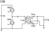
도 3b는 도 1에 도시된 전원부의 다른 일 실시예를 나타내는 회로도이다.
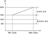
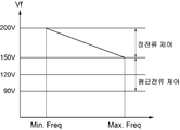
도 4a는 도 1 및 도 2에 도시된 제1제어모듈의 동작을 나타내는 그래프이다.
도 4b는 도 1 및 도 2에 도시된 제1제어모듈의 동작을 나타내는 그래프이다.
도 4c는 도 1 및 도 2에 도시된 제2제어모듈의 동작을 나타내는 그래프이다.
도 5a는 도 1 및 도 2에 도시된 제어부가 정전류구간에서 부하에 흐르는 구동전류를 나타내는 그래프이다.
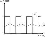
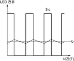
도 5b는 도 1 및 도 2에 도시된 제어부가 평균전류구간에서 부하에 흐르는 구동전류를 나타내는 그래프이다.
도 5c는 도 1 및 도 2에 도시된 제어부가 평균전류구간에서 부하에 흐르는 구동전류를 나타내는 그래프이다.
도 6는 도 1 및 도 2에 도시된 전원장치의 구동방법을 나타내는 순서도이다.
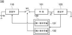
110: 전원부 120: 센싱부
130: 제어부 131: 제1제어모듈
131: 제2제어모듈 M1: 제1스위치
Id: 구동전류 dc: 직류전원
Claims (20)
- 부하로 구동전류를 공급하는 전원부;
상기 구동전류의 크기를 감지하는 센싱부;
온오프시간을 조절하여 상기 구동전류의 흐름을 제어하는 제1스위치; 및
상기 센싱부에서 감지된 상기 구동전류의 크기에 대응하여 정전류구동과 평균전류구동으로 구분하여 동작하며, 상기 정전류구동에서는 상기 구동전류의 크기가 기설정된 소정값이 되도록 상기 전원부를 제어하고, 상기 평균전류구동에서는 상기 온오프시간을 조절하여 상기 구동전류의 평균 크기가 기설정된 소정값이 되도록 하는 제어부를 포함하는 전원장치. - 제1항에 있어서,
상기 제어부는, 상기 정전류구동과 상기 평균전류구동에서 상기 전원부를 제어하여 상기 구동전류를 생성하는 제1제어모듈과, 상기 센싱부에서 감지된 상기 구동전류의 크기가 기 설정된 소정값을 초과하는 경우, 상기 온오프시간을 조절하여 상기 구동전류의 크기의 평균이 상기 기설정된 소정값이 되도록 조절하는 제2제어모듈을 포함하는 전원장치. - 제2항에 있어서,
상기 전원부는 인덕터와 상기 인덕터에 연결되어 있는 제2스위치를 포함하고, 상기 제1제어모듈은 상기 제2스위치의 턴온 또는 턴오프를 조절하여 상기 인덕터에 흐르는 전류의 크기를 조절하는 제1제어신호를 출력하는 전원장치. - 제3항에 있어서,
상기 제1제어신호는 상기 센싱부에서 감지된 상기 구동전류의 크기에 대응하여 듀티비가 조절되는 전원장치. - 제3항에 있어서,
상기 제1제어신호는 상기 센싱부에서 감지된 상기 구동전류의 크기에 대응하여 주파수가 조절되는 전원장치. - 제2항에 있어서,
상기 제2제어모듈은 상기 센싱부에서 감지된 구동전류의 크기와 기준전류를 비교하여 상기 구동전류의 크기가 기설정된 소정값을 초과하는지를 판단하는 전원장치. - 제6항에 있어서,
상기 제2제어모듈은 상기 구동전류의 크기가 상기 기준전류의 크기를 초과한 것으로 판단하면, 상기 구동전류의 크기에 대응하여 상기 온오프시간을 조절하는 제2제어신호를 출력하는 전원장치. - 제2항에 있어서,
상기 제2제어모듈은,
부(-)입력단으로 상기 센싱부에서 감지된 구동전류에 대응하는 전압을 입력받고 정(+)입력단으로 기준전류에 대응하는 전압을 입력받는 비교기와, 정(+)입력단으로 상기 비교기의 출력신호를 입력받고 부(-)입력단으로 소정의 펄스를 입력받아 상기 비교기의 출력신호에 대응하여 듀티비가 조절되는 제2제어신호를 출력하는 신호출력기를 포함하는 전원장치. - 부하로 구동전류를 공급하는 전원부;
상기 구동전류의 크기를 감지하는 센싱부;
온오프시간을 조절하여 상기 구동전류의 흐름을 제어하는 제1스위치; 및
상기 전원부에서 부하로 공급하는 상기 구동전류의 크기와 상기 제1스위치의 스위칭동작을 제어하고 상기 센싱부에서 감지된 결과에 대응하여 상기 전원부를 제어함으로써, 상기 전원부에서 공급하는 상기 구동전류의 크기를 조절하되, 상기 구동전류의 크기가 기설정된 소정값을 초과하는 경우, 상기 제1스위치의 온오프시간을 조절하여 상기 구동전류의 크기의 평균이 상기 기설정된 소정값이 되도록 제어하는 제어부를 포함하는 전원장치. - 제9항에 있어서,
상기 제어부는, 상기 센싱부에서 감지된 결과에 대응하여 상기 전원부를 제어함으로써, 상기 전원부에서 공급하는 상기 구동전류의 크기를 조절하는 제1제어모듈과 상기 구동전류의 크기가 기 설정된 소정값을 초과하는 경우, 상기 스위치의 온오프시간을 제어하여 상기 구동전류의 크기의 평균이 상기 기설정된 소정값이 되도록 제어하는 제2제어모듈을 포함하는 전원장치. - 제10항에 있어서,
상기 전원부는 인덕터와 상기 인덕터에 연결되어 있는 제2스위치를 포함하고, 상기 제1제어모듈은 상기 제2스위치의 턴온 또는 턴오프를 조절하여 상기 인덕터에 흐르는 전류의 크기를 조절하는 제1제어신호를 출력하는 전원장치. - 제11항에 있어서,
상기 제1제어신호는 상기 구동전류의 크기에 대응하여 듀티비가 조절되는 전원장치. - 제11항에 있어서,
상기 제1제어신호는 상기 구동전류의 크기에 대응하여 주파수가 조절되는 전원장치. - 제10항에 있어서,
상기 제2제어모듈은 상기 센싱부에서 감지된 전류의 크기와 기준전류를 비교하여 상기 구동전류의 크기가 기설정된 소정값을 초과하는지를 판단하는 전원장치. - 제14항에 있어서,
상기 제2제어모듈은 상기 구동전류의 크기가 상기 기준전류의 크기를 초과한 것으로 판단하면, 상기 구동전류의 크기에 대응하여 상기 온오프시간을 조절하는 제2제어신호를 출력하는 전원장치. - 제10항에 있어서,
상기 제2제어모듈은,
부(-)입력단으로 상기 센싱부에서 감지된 구동전류에 대응하는 전압을 입력받고 정(+)입력단으로 기준전류에 대응하는 전압을 입력받는 비교기와, 정(+)입력단으로 비교기의 출력신호를 입력받고 부(-)입력단으로 소정의 펄스를 입력받아 상기 비교기의 출력신호에 대응하여 듀티비가 조절되는 제2제어신호를 출력하는 신호출력기를 포함하는 전원장치. - 인덕터에 흐르는 전류를 제어함으로써 구동전류를 생성하는 전원부를 포함하는 전원장치의 구동방법에 있어서,
부하에 흐르는 상기 구동전류를 감지하는 단계;
감지된 상기 구동전류에 대응하여 상기 인덕터에 흐르는 전류의 양을 조절함으로써, 상기 구동전류의 크기를 조절하는 단계; 및
감지된 상기 구동전류의 크기가 기 설정된 소정값을 초과한 것으로 판단되면, 구동전류의 흐름을 온오프하여 상기 구동전류의 크기의 평균을 상기 기설정된 소정값이 되도록 하는 단계를 포함하는 전원장치의 구동방법. - 제17항에 있어서,
상기 구동전류의 크기를 조절하는 단계에서, 상기 구동전류의 크기는 인덕터에 흐르는 전류의 온오프시간을 조절하는 전원장치의 구동방법. - 제18항에 있어서,
상기 온오프시간을 조절하는 것은 제어신호의 주파수를 다르게 하여 조절하는 전원장치의 구동방법. - 제18항에 있어서,
상기 온오프시간을 조절하는 것은 제어신호의 듀티비를 다르게 하여 조절하는 전원장치의 구동방법.
Priority Applications (3)
| Application Number | Priority Date | Filing Date | Title |
|---|---|---|---|
| KR1020140093197A KR20160011908A (ko) | 2014-07-23 | 2014-07-23 | 전원장치 및 그의 구동방법 |
| EP15177438.7A EP2978280A3 (en) | 2014-07-23 | 2015-07-20 | Power converter and method for driving the same |
| US14/803,159 US20160028316A1 (en) | 2014-07-23 | 2015-07-20 | Power converter and method for driving the same |
Applications Claiming Priority (1)
| Application Number | Priority Date | Filing Date | Title |
|---|---|---|---|
| KR1020140093197A KR20160011908A (ko) | 2014-07-23 | 2014-07-23 | 전원장치 및 그의 구동방법 |
Publications (1)
| Publication Number | Publication Date |
|---|---|
| KR20160011908A true KR20160011908A (ko) | 2016-02-02 |
Family
ID=53716380
Family Applications (1)
| Application Number | Title | Priority Date | Filing Date |
|---|---|---|---|
| KR1020140093197A Withdrawn KR20160011908A (ko) | 2014-07-23 | 2014-07-23 | 전원장치 및 그의 구동방법 |
Country Status (3)
| Country | Link |
|---|---|
| US (1) | US20160028316A1 (ko) |
| EP (1) | EP2978280A3 (ko) |
| KR (1) | KR20160011908A (ko) |
Families Citing this family (2)
| Publication number | Priority date | Publication date | Assignee | Title |
|---|---|---|---|---|
| KR102316085B1 (ko) * | 2015-02-23 | 2021-10-25 | 엘지전자 주식회사 | 의류처리장치의 제어방법 |
| US10185295B2 (en) * | 2015-09-30 | 2019-01-22 | Osram Sylvania Inc. | Dynamic control of switching frequency in a switch mode power converter |
Family Cites Families (16)
| Publication number | Priority date | Publication date | Assignee | Title |
|---|---|---|---|---|
| US7202608B2 (en) * | 2004-06-30 | 2007-04-10 | Tir Systems Ltd. | Switched constant current driving and control circuit |
| JP4646110B2 (ja) * | 2004-10-22 | 2011-03-09 | 株式会社中川研究所 | 半導体発光素子用電源および照明装置 |
| US7499007B2 (en) * | 2005-04-01 | 2009-03-03 | Analog Devices, Inc. | Maximizing efficiency of battery-powered LED drivers |
| EP1967049A4 (en) * | 2005-12-20 | 2016-03-02 | Koninkl Philips Nv | METHOD AND DEVICE FOR CONTROLLING THE POWER SUPPLY OF ELECTRONIC EQUIPMENT |
| US7944153B2 (en) * | 2006-12-15 | 2011-05-17 | Intersil Americas Inc. | Constant current light emitting diode (LED) driver circuit and method |
| US8174204B2 (en) * | 2007-03-12 | 2012-05-08 | Cirrus Logic, Inc. | Lighting system with power factor correction control data determined from a phase modulated signal |
| US8111001B2 (en) * | 2007-07-17 | 2012-02-07 | Cree, Inc. | LED with integrated constant current driver |
| US7804258B2 (en) * | 2007-10-30 | 2010-09-28 | Bin Zhao | Circuit for providing an approximately constant resistance and/or current and method therefor |
| US8022634B2 (en) * | 2008-02-05 | 2011-09-20 | Intersil Americas Inc. | Method and system for dimming AC-powered light emitting diode (LED) lighting systems using conventional incandescent dimmers |
| US7759881B1 (en) * | 2008-03-31 | 2010-07-20 | Cirrus Logic, Inc. | LED lighting system with a multiple mode current control dimming strategy |
| US9386653B2 (en) * | 2008-12-12 | 2016-07-05 | O2Micro Inc | Circuits and methods for driving light sources |
| US9030122B2 (en) * | 2008-12-12 | 2015-05-12 | O2Micro, Inc. | Circuits and methods for driving LED light sources |
| US8492988B2 (en) * | 2009-10-07 | 2013-07-23 | Lutron Electronics Co., Inc. | Configurable load control device for light-emitting diode light sources |
| WO2011092606A1 (en) * | 2010-02-01 | 2011-08-04 | Koninklijke Philips Electronics N.V. | Apparatus for enabling smooth start-up of solid-state lighting unit |
| US8994639B2 (en) * | 2012-05-16 | 2015-03-31 | Shenzhen China Star Optoelectronics Technology Co., Ltd. | LED backlight driving circuit, backlight module, and LCD device |
| US8884548B2 (en) * | 2013-02-28 | 2014-11-11 | Asahi Kasei Microdevices Corporation | Power factor correction converter with current regulated output |
-
2014
- 2014-07-23 KR KR1020140093197A patent/KR20160011908A/ko not_active Withdrawn
-
2015
- 2015-07-20 US US14/803,159 patent/US20160028316A1/en not_active Abandoned
- 2015-07-20 EP EP15177438.7A patent/EP2978280A3/en not_active Withdrawn
Also Published As
| Publication number | Publication date |
|---|---|
| EP2978280A3 (en) | 2016-02-10 |
| EP2978280A2 (en) | 2016-01-27 |
| US20160028316A1 (en) | 2016-01-28 |
Similar Documents
| Publication | Publication Date | Title |
|---|---|---|
| TWI528856B (zh) | Led調光驅動器 | |
| US20110215731A1 (en) | Led illumination driving apparatus | |
| TWI510131B (zh) | 發光元件驅動電路及其控制方法 | |
| KR20160021507A (ko) | 전원장치 및 그의 구동방법 | |
| JP4983735B2 (ja) | 電源制御用半導体集積回路 | |
| TW201234919A (en) | Single power stage for LED driver and other power supplies | |
| CN101193484A (zh) | Led驱动器 | |
| Hu et al. | A novel LED driver with adaptive drive voltage | |
| KR101698948B1 (ko) | 복수의 구동단 및 선로/부하 레귤레이션 제어를 구비한 발광 다이오드 조명 장치 | |
| KR20110065172A (ko) | 디스플레이장치 및 그 구동방법 | |
| ATE536079T1 (de) | Schalt-konstantstromansteuer- und steuerschaltung | |
| KR20090076330A (ko) | 시간 분할 다중 출력 직류-직류 컨버터를 갖는 발광 장치및 전원 장치 | |
| KR102006966B1 (ko) | Led 발광 장치의 구동 장치 및 구동 방법 | |
| KR20150001033A (ko) | 전원 공급 장치 | |
| JP4666316B2 (ja) | 電流感知回路ループのある定電流調整器 | |
| US20130099671A1 (en) | Power supply device and driving device | |
| JP2010153566A (ja) | Led駆動方式 | |
| CN105917738B (zh) | 基于纹波的发光二极管驱动 | |
| EP2978280A2 (en) | Power converter and method for driving the same | |
| KR101132408B1 (ko) | 엘이디 구동 장치 | |
| US20160079863A1 (en) | Power converter and driving method for the same | |
| US8917028B2 (en) | Driving circuit | |
| JP2009054998A (ja) | 駆動装置 | |
| KR101320244B1 (ko) | 발광 다이오드 구동 장치 | |
| KR101188236B1 (ko) | 발광소자 조명 제어 장치 |
Legal Events
| Date | Code | Title | Description |
|---|---|---|---|
| PA0109 | Patent application |
St.27 status event code: A-0-1-A10-A12-nap-PA0109 |
|
| R17-X000 | Change to representative recorded |
St.27 status event code: A-3-3-R10-R17-oth-X000 |
|
| N231 | Notification of change of applicant | ||
| PN2301 | Change of applicant |
St.27 status event code: A-3-3-R10-R13-asn-PN2301 St.27 status event code: A-3-3-R10-R11-asn-PN2301 |
|
| R17-X000 | Change to representative recorded |
St.27 status event code: A-3-3-R10-R17-oth-X000 |
|
| PG1501 | Laying open of application |
St.27 status event code: A-1-1-Q10-Q12-nap-PG1501 |
|
| R18-X000 | Changes to party contact information recorded |
St.27 status event code: A-3-3-R10-R18-oth-X000 |
|
| PN2301 | Change of applicant |
St.27 status event code: A-3-3-R10-R13-asn-PN2301 St.27 status event code: A-3-3-R10-R11-asn-PN2301 |
|
| R18-X000 | Changes to party contact information recorded |
St.27 status event code: A-3-3-R10-R18-oth-X000 |
|
| PC1203 | Withdrawal of no request for examination |
St.27 status event code: N-1-6-B10-B12-nap-PC1203 |
|
| WITN | Application deemed withdrawn, e.g. because no request for examination was filed or no examination fee was paid | ||
| P22-X000 | Classification modified |
St.27 status event code: A-2-2-P10-P22-nap-X000 |
|
| P22-X000 | Classification modified |
St.27 status event code: A-2-2-P10-P22-nap-X000 |
|
| R18-X000 | Changes to party contact information recorded |
St.27 status event code: A-3-3-R10-R18-oth-X000 |
|
| R18 | Changes to party contact information recorded |
Free format text: ST27 STATUS EVENT CODE: A-3-3-R10-R18-OTH-X000 (AS PROVIDED BY THE NATIONAL OFFICE) |
|
| R18-X000 | Changes to party contact information recorded |
St.27 status event code: A-3-3-R10-R18-oth-X000 |
|
| R18 | Changes to party contact information recorded |
Free format text: ST27 STATUS EVENT CODE: A-3-3-R10-R18-OTH-X000 (AS PROVIDED BY THE NATIONAL OFFICE) |
|
| R18-X000 | Changes to party contact information recorded |
St.27 status event code: A-3-3-R10-R18-oth-X000 |