KR20160041402A - Pouch type secondary battery and a method of making the same - Google Patents
Pouch type secondary battery and a method of making the same Download PDFInfo
- Publication number
- KR20160041402A KR20160041402A KR1020140135178A KR20140135178A KR20160041402A KR 20160041402 A KR20160041402 A KR 20160041402A KR 1020140135178 A KR1020140135178 A KR 1020140135178A KR 20140135178 A KR20140135178 A KR 20140135178A KR 20160041402 A KR20160041402 A KR 20160041402A
- Authority
- KR
- South Korea
- Prior art keywords
- pouch
- secondary battery
- sealing
- electrode assembly
- type secondary
- Prior art date
- Legal status (The legal status is an assumption and is not a legal conclusion. Google has not performed a legal analysis and makes no representation as to the accuracy of the status listed.)
- Ceased
Links
- 238000004519 manufacturing process Methods 0.000 title description 9
- 238000007789 sealing Methods 0.000 claims abstract description 87
- 238000000034 method Methods 0.000 claims description 12
- 238000005452 bending Methods 0.000 claims description 3
- 238000001816 cooling Methods 0.000 abstract description 23
- 239000003792 electrolyte Substances 0.000 description 4
- 239000010410 layer Substances 0.000 description 4
- 239000012790 adhesive layer Substances 0.000 description 3
- 239000000463 material Substances 0.000 description 3
- 229910052751 metal Inorganic materials 0.000 description 3
- 239000002184 metal Substances 0.000 description 3
- 238000012986 modification Methods 0.000 description 3
- 230000004048 modification Effects 0.000 description 3
- 239000000047 product Substances 0.000 description 3
- 239000000853 adhesive Substances 0.000 description 2
- 230000001070 adhesive effect Effects 0.000 description 2
- 229910052782 aluminium Inorganic materials 0.000 description 2
- XAGFODPZIPBFFR-UHFFFAOYSA-N aluminium Chemical compound [Al] XAGFODPZIPBFFR-UHFFFAOYSA-N 0.000 description 2
- 230000000712 assembly Effects 0.000 description 2
- 238000000429 assembly Methods 0.000 description 2
- 239000002826 coolant Substances 0.000 description 2
- 239000010949 copper Substances 0.000 description 2
- 239000008151 electrolyte solution Substances 0.000 description 2
- 239000007773 negative electrode material Substances 0.000 description 2
- 239000007774 positive electrode material Substances 0.000 description 2
- 239000000565 sealant Substances 0.000 description 2
- 238000012546 transfer Methods 0.000 description 2
- RYGMFSIKBFXOCR-UHFFFAOYSA-N Copper Chemical compound [Cu] RYGMFSIKBFXOCR-UHFFFAOYSA-N 0.000 description 1
- 239000011149 active material Substances 0.000 description 1
- 230000000903 blocking effect Effects 0.000 description 1
- 239000006227 byproduct Substances 0.000 description 1
- 239000000498 cooling water Substances 0.000 description 1
- 229910052802 copper Inorganic materials 0.000 description 1
- 230000006866 deterioration Effects 0.000 description 1
- 238000011161 development Methods 0.000 description 1
- 238000007599 discharging Methods 0.000 description 1
- 230000000694 effects Effects 0.000 description 1
- 238000003487 electrochemical reaction Methods 0.000 description 1
- 238000004146 energy storage Methods 0.000 description 1
- 230000002708 enhancing effect Effects 0.000 description 1
- 230000007613 environmental effect Effects 0.000 description 1
- 230000001747 exhibiting effect Effects 0.000 description 1
- 238000004880 explosion Methods 0.000 description 1
- 239000002803 fossil fuel Substances 0.000 description 1
- 230000010354 integration Effects 0.000 description 1
- 238000012544 monitoring process Methods 0.000 description 1
- 230000035699 permeability Effects 0.000 description 1
- 239000002861 polymer material Substances 0.000 description 1
- 238000012545 processing Methods 0.000 description 1
- 239000003507 refrigerant Substances 0.000 description 1
- XLYOFNOQVPJJNP-UHFFFAOYSA-N water Substances O XLYOFNOQVPJJNP-UHFFFAOYSA-N 0.000 description 1
Images




Classifications
-
- H—ELECTRICITY
- H01—ELECTRIC ELEMENTS
- H01M—PROCESSES OR MEANS, e.g. BATTERIES, FOR THE DIRECT CONVERSION OF CHEMICAL ENERGY INTO ELECTRICAL ENERGY
- H01M50/00—Constructional details or processes of manufacture of the non-active parts of electrochemical cells other than fuel cells, e.g. hybrid cells
- H01M50/10—Primary casings; Jackets or wrappings
- H01M50/147—Lids or covers
-
- H—ELECTRICITY
- H01—ELECTRIC ELEMENTS
- H01M—PROCESSES OR MEANS, e.g. BATTERIES, FOR THE DIRECT CONVERSION OF CHEMICAL ENERGY INTO ELECTRICAL ENERGY
- H01M10/00—Secondary cells; Manufacture thereof
- H01M10/04—Construction or manufacture in general
- H01M10/0413—Large-sized flat cells or batteries for motive or stationary systems with plate-like electrodes
-
- H—ELECTRICITY
- H01—ELECTRIC ELEMENTS
- H01M—PROCESSES OR MEANS, e.g. BATTERIES, FOR THE DIRECT CONVERSION OF CHEMICAL ENERGY INTO ELECTRICAL ENERGY
- H01M10/00—Secondary cells; Manufacture thereof
- H01M10/05—Accumulators with non-aqueous electrolyte
- H01M10/058—Construction or manufacture
-
- H—ELECTRICITY
- H01—ELECTRIC ELEMENTS
- H01M—PROCESSES OR MEANS, e.g. BATTERIES, FOR THE DIRECT CONVERSION OF CHEMICAL ENERGY INTO ELECTRICAL ENERGY
- H01M50/00—Constructional details or processes of manufacture of the non-active parts of electrochemical cells other than fuel cells, e.g. hybrid cells
- H01M50/10—Primary casings; Jackets or wrappings
- H01M50/102—Primary casings; Jackets or wrappings characterised by their shape or physical structure
- H01M50/105—Pouches or flexible bags
-
- H—ELECTRICITY
- H01—ELECTRIC ELEMENTS
- H01M—PROCESSES OR MEANS, e.g. BATTERIES, FOR THE DIRECT CONVERSION OF CHEMICAL ENERGY INTO ELECTRICAL ENERGY
- H01M50/00—Constructional details or processes of manufacture of the non-active parts of electrochemical cells other than fuel cells, e.g. hybrid cells
- H01M50/10—Primary casings; Jackets or wrappings
- H01M50/116—Primary casings; Jackets or wrappings characterised by the material
-
- H—ELECTRICITY
- H01—ELECTRIC ELEMENTS
- H01M—PROCESSES OR MEANS, e.g. BATTERIES, FOR THE DIRECT CONVERSION OF CHEMICAL ENERGY INTO ELECTRICAL ENERGY
- H01M50/00—Constructional details or processes of manufacture of the non-active parts of electrochemical cells other than fuel cells, e.g. hybrid cells
- H01M50/20—Mountings; Secondary casings or frames; Racks, modules or packs; Suspension devices; Shock absorbers; Transport or carrying devices; Holders
-
- H—ELECTRICITY
- H01—ELECTRIC ELEMENTS
- H01M—PROCESSES OR MEANS, e.g. BATTERIES, FOR THE DIRECT CONVERSION OF CHEMICAL ENERGY INTO ELECTRICAL ENERGY
- H01M50/00—Constructional details or processes of manufacture of the non-active parts of electrochemical cells other than fuel cells, e.g. hybrid cells
- H01M50/50—Current conducting connections for cells or batteries
- H01M50/531—Electrode connections inside a battery casing
-
- H—ELECTRICITY
- H01—ELECTRIC ELEMENTS
- H01M—PROCESSES OR MEANS, e.g. BATTERIES, FOR THE DIRECT CONVERSION OF CHEMICAL ENERGY INTO ELECTRICAL ENERGY
- H01M2220/00—Batteries for particular applications
- H01M2220/20—Batteries in motive systems, e.g. vehicle, ship, plane
-
- Y—GENERAL TAGGING OF NEW TECHNOLOGICAL DEVELOPMENTS; GENERAL TAGGING OF CROSS-SECTIONAL TECHNOLOGIES SPANNING OVER SEVERAL SECTIONS OF THE IPC; TECHNICAL SUBJECTS COVERED BY FORMER USPC CROSS-REFERENCE ART COLLECTIONS [XRACs] AND DIGESTS
- Y02—TECHNOLOGIES OR APPLICATIONS FOR MITIGATION OR ADAPTATION AGAINST CLIMATE CHANGE
- Y02E—REDUCTION OF GREENHOUSE GAS [GHG] EMISSIONS, RELATED TO ENERGY GENERATION, TRANSMISSION OR DISTRIBUTION
- Y02E60/00—Enabling technologies; Technologies with a potential or indirect contribution to GHG emissions mitigation
- Y02E60/10—Energy storage using batteries
-
- Y—GENERAL TAGGING OF NEW TECHNOLOGICAL DEVELOPMENTS; GENERAL TAGGING OF CROSS-SECTIONAL TECHNOLOGIES SPANNING OVER SEVERAL SECTIONS OF THE IPC; TECHNICAL SUBJECTS COVERED BY FORMER USPC CROSS-REFERENCE ART COLLECTIONS [XRACs] AND DIGESTS
- Y02—TECHNOLOGIES OR APPLICATIONS FOR MITIGATION OR ADAPTATION AGAINST CLIMATE CHANGE
- Y02P—CLIMATE CHANGE MITIGATION TECHNOLOGIES IN THE PRODUCTION OR PROCESSING OF GOODS
- Y02P70/00—Climate change mitigation technologies in the production process for final industrial or consumer products
- Y02P70/50—Manufacturing or production processes characterised by the final manufactured product
Landscapes
- Chemical & Material Sciences (AREA)
- Chemical Kinetics & Catalysis (AREA)
- Electrochemistry (AREA)
- General Chemical & Material Sciences (AREA)
- Engineering & Computer Science (AREA)
- Manufacturing & Machinery (AREA)
- Sealing Battery Cases Or Jackets (AREA)
Abstract
Description
본 발명은 파우치형 이차 전지에 관한 것으로서, 보다 상세하게는 컴팩트(Compact)한 구조를 가지며, 향상된 냉각 효과를 발현할 수 있는 파우치형 이차 전지에 관한 것이다. The present invention relates to a pouch type secondary battery, and more particularly, to a pouch type secondary battery having a compact structure and exhibiting an improved cooling effect.
제품군에 따른 적용 용이성이 높고, 높은 에너지 밀도 등의 전기적 특성을 가지는 이차전지는 휴대용 기기뿐만 아니라 전기적 구동원에 의하여 구동하는 전기차량(EV, Electric Vehicle) 또는 하이브리드 차량(HEV, Hybrid Electric Vehicle), 전력 저장 장치(Energy Storage System) 등에 보편적으로 응용되고 있다. 이러한 이차전지는 화석 연료의 사용을 획기적으로 감소시킬 수 있다는 일차적인 장점뿐만 아니라 에너지의 사용에 따른 부산물이 전혀 발생되지 않는다는 점에서 친환경 및 에너지 효율성 제고를 위한 새로운 에너지원으로 주목 받고 있다.Secondary batteries having high electrical characteristics such as high energy density and high ease of application according to the product group can be applied not only to portable devices but also to electric vehicles (EVs) or hybrid electric vehicles (HEVs) driven by electric driving sources, Storage devices (Energy Storage System) and so on. Such a secondary battery is not only a primary advantage that the use of fossil fuel can be drastically reduced, but also produces no by-products resulting from the use of energy, and thus is attracting attention as a new energy source for enhancing environmental friendliness and energy efficiency.
전기 차량 등에 적용되는 배터리 팩은 고출력을 얻기 위해 복수의 단위 배터리 셀(cell)을 포함하는 다수의 셀 어셈블리를 직렬로 연결한 구조를 가지고 있다. 그리고, 상기 단위 베터리 셀은 양극 및 음극 집전체, 세퍼레이터, 활물질, 전해액 등을 포함하여 구성 요소들 간의 전기 화학적 반응에 의하여 반복적인 충방전이 가능하다.A battery pack applied to an electric vehicle has a structure in which a plurality of cell assemblies including a plurality of unit battery cells are connected in series in order to obtain high output. The unit battery cell may include a positive electrode and a negative electrode current collector, a separator, an active material, an electrolyte, and the like, and may be repeatedly charged and discharged by electrochemical reaction between the components.
이러한 기본적 구조에 더하여, 배터리 팩은 모터 등의 구동부하에 대한 전력 공급 제어, 전류 또는 전압 등의 전기적 특성값 측정, 충방전 제어, 전압의 평활화(equalization) 제어, SOC(State Of Charge)의 추정 등을 위한 알고리즘이 적용되어 이차전지의 상태를 모니터링하고 제어하는 BMS(Battery Management System) 등이 추가적으로 포함되어 구성될 수 있다.In addition to this basic structure, the battery pack has a function of controlling electric power supply to a driving load of a motor and the like, measuring electric characteristic values such as a current or a voltage, controlling charging and discharging, controlling voltage equalization, estimating state of charge (SOC) (Battery Management System) for monitoring and controlling the state of the secondary battery by applying an algorithm to the secondary battery.
이러한 중대형 배터리 팩은 가능한 컴팩트(compact)하고 중량이 작게 제조되는 것이 바람직하므로, 집적도가 좋고 중량 대비 용량이 큰 각형 전지 또는 파우치형 전지등이 중대형 배터리 팩의 단위 배터리 셀로서 주로 사용되고 있다. 특히, 파우치형 배터리 셀은 제조단가가 저렴하고 중량이 작으며 형태 변형이 용이한 이점으로 최근 많은 관심을 모으고 있다.Since such a middle- or large-sized battery pack is preferably compact and small in weight, a prismatic battery or a pouch-type battery having a high degree of integration and a large capacity by weight is mainly used as a unit battery cell of a middle- or large-sized battery pack. Particularly, pouch type battery cells have recently attracted a lot of attention due to their low manufacturing cost, small weight, and easy shape deformation.
한편, 중대형 배터리 팩은 다수의 셀 어셈블리가 좁은 공간에 밀집되는 형태로 제조되기 때문에, 각 배터리 셀에서 발생한 열을 방출하는 것이 매우 중요하다. 배터리 셀의 열이 효과적으로 방출되지 못하면, 성능이 제대로 발휘되지 못할 수 있고, 열화가 촉진되어 발화 또는 폭발을 유발할 수 있다. 따라서, 관련업계는 고출력 대용량이면서 컴팩트한 구조와 냉각 효율이 우수한 중대형 배터리 팩의 개발에 초점을 맞추고 있다. On the other hand, since the middle- or large-sized battery pack is manufactured in such a manner that a plurality of cell assemblies are densely packed in a narrow space, it is very important to emit heat generated in each battery cell. If the heat of the battery cell is not effectively released, the performance may not be exhibited properly, and deterioration may be promoted, which may cause ignition or explosion. Accordingly, the related industry is focused on the development of a large-sized, large-capacity, compact structure and a large-sized battery pack with excellent cooling efficiency.
도 1은 종래의 파우치형 이차 전지를 포함한 배터리 모듈의 일부 구성을 개략적으로 도시한 도면이다. 1 is a view schematically showing a part of a battery module including a conventional pouch type secondary battery.
일반적으로 파우치형 이차 전지는, 전극 조립체와 전극 조립체(11)를 수용하는 파우치 외장재로 이루진다. 여기서 파우치 외장재는 상부 파우치와 하부 파우치로 구성되며, 이러한 상부 파우치와 하부 파우치의 외주면에는 실링부가 구비되고 실링부가 서로 접착됨으로써 전극 조립체(11)가 수용된 내부 공간이 밀폐된다.Generally, the pouch type secondary battery is formed of a pouch outer casing that accommodates an electrode assembly and an electrode assembly (11). Here, the pouch exterior member is composed of the upper pouch and the lower pouch. The outer periphery of the upper pouch and the lower pouch are provided with sealing portions and the sealing portions are bonded to each other, thereby sealing the internal space in which the
그런데, 셀 어셈블리를 구성하는 파우치형 이차 전지(10)의 실링부, 특히 전극 리드가 노출되어 있지 않은 윙(12, wing) 부분은 제품의 직접화에 방해된다. 이에 따라 종래의 경우에는 윙(12, wing)부분을 파우치형 이차 전지(10)의 좌측면부(L) 및/또는 우측면부에 겹치도록 접어 데스 스페이스(dead space)를 줄이고자 하는 시도가 있다. 그런데, 도 1에 도시된 바와 같이, 종래의 윙(12)을 파우치형 이차 전지(10)의 좌측면부(L) 및/또는 우측면부에 겹치도록 접은 형태는, 파우치형 이차 전지(10)의 냉각 시, 윙(11) 부분이 접힌 영역과 그렇지 않은 영역간에 온도 편차를 발생시킬 수 있다. 즉, 도 1에서와 같이, 파우치형 이차 전지(10)의 좌측면부(L) 또는 우측면부에 인접한 위치의 냉각부재(13)에 파우치형 이차 전지(10)에서 발생한 열이 전달될 때, 윙(11) 부분이 겹쳐져 있는 부분은 그렇지 않은 부분보다 열차단성이 높아진다. 따라서 윙(11)이 중첩된 영역의 경우, 전극 조립체(11)에서 냉각부재(13) 방향으로 열이 제대로 전달되지 못해 파우치형 이차 전지(10)의 전체 냉각 효율을 떨어뜨리는 요인이 될 수 있다.However, the sealing portion of the pouch-type
따라서, 본 발명은 상기와 같은 문제점을 해결하기 위해 창안된 것으로서, 종래 파우치형 이차 전지의 윙(wing)을 효과적으로 공간 배치시킴으로써 보다 컴팩트(compact)한 형태를 가질 수 있을 뿐만 아니라 냉각 효율을 향상시킬 수 있는 파우치형 이차 전지를 제공하는 것이다. SUMMARY OF THE INVENTION Accordingly, it is an object of the present invention to provide a pouch type rechargeable battery which is capable of effectively achieving a compact shape by effectively arranging a wing of a conventional pouch type secondary battery, A secondary battery, and a secondary battery.
본 발명의 다른 목적 및 장점들은 하기의 설명에 의해서 이해될 수 있으며, 본 발명의 실시예에 의해 보다 분명하게 알게 될 것이다. 또한, 본 발명의 목적 및 장점들은 특허 청구 범위에 나타낸 수단 및 그 조합에 의해 실현될 수 있음을 쉽게 알 수 있을 것이다.Other objects and advantages of the present invention will become apparent from the following description, and it will be understood by those skilled in the art that the present invention is not limited thereto. It will also be readily apparent that the objects and advantages of the invention may be realized and attained by means of the instrumentalities and combinations particularly pointed out in the appended claims.
본 발명에 따르면, 전극 조립체; 상기 전극 조립체와 연결되는 전극 리드; 및 중앙 영역이 판상형인 상부 파우치와, 중앙 영역에 상기 전극 조립체를 수용하는 공간을 형성하는 하부 파우치를 구비하며, 상기 상부 파우치와 상기 하부 파우치의 가장자리에 실링부를 구비하여 밀폐되는 파우치형 외장재를 포함하며, 상기 실링부는, 적어도 일측이 상기 상부 파우치의 상부로 폴딩된 상면배치실링부를 구비하는 파우치형 이차 전지가 제공될 수 있다.According to the present invention, there is provided an electrode assembly comprising: an electrode assembly; An electrode lead connected to the electrode assembly; And an upper pouch having a central region in a plate-like shape and a lower pouch forming a space for accommodating the electrode assembly in a central region, and a pouch-type sheathing member having a sealing portion at an edge of the upper pouch and the lower pouch, And the sealing portion may include a top surface disposing sealing portion having at least one side thereof folded over the upper portion of the upper pouch.
상기 상면배치실링부는, 상기 실링부 중에서 상기 전극 리드가 노출되지 않는 상기 파우치 외장재의 양측면 가장자리 부분이 상기 상부 파우치의 상부로 폴딩되어 형성될 수 있다. The upper surface disposition sealing portion may be formed by folding the upper surface of the upper pouch with both side edge portions of the pouch exterior material from which the electrode lead is not exposed.
상기 상면배치실링부는, 상기 상부 파우치의 상면에 나란하게 접촉배치될 수 있다. The upper surface disposition sealing portion may be disposed in contact with the upper surface of the upper pouch in parallel.
상기 상면배치실링부는, 적어도 2회이상 절곡된 형상을 가질 수 있다.The upper surface disposition sealing portion may have a shape bent at least twice.
상기 상면배치실링부는, 상기 상부 파우치의 상면으로 소정의 곡률 반경을 가지는 굴곡된 형상을 가질 수 있다.The upper surface disposition sealing portion may have a curved shape having a predetermined curvature radius on the upper surface of the upper pouch.
상기 상면배치실링부는, 상기 상부 파우치의 상면에 접착될 수 있다.The top surface disposition sealing portion may be adhered to the upper surface of the upper pouch.
본 발명의 다른 양태에 따르면, 전술한 파우치형 이차 전지를 포함하는 배터리 팩이 제공될 수 있다.According to another aspect of the present invention, a battery pack including the above-described pouch-type secondary battery can be provided.
본 발명의 또 다른 양태에 따르면, 전극 조립체의 수납공간이 형성된 하부 파우치와, 판상형의 상부 파우치를 준비하는 단계; 상기 하부 파우치의 수납공간에 전극 리드가 외부에 노출되도록 상기 전극 조립체를 수납하는 단계; 상기 하부 파우치와 상기 상부 파우치의 가장자리에 형성된 실링부를 실링(sealing)하는 단계; 및 상기 실링부 중에서 적어도 일측부를 상기 상부 파우치의 상부로 폴딩시키는 단계를 포함하는 파우치형 이차 전지 제조방법이 제공될 수 있다.According to another aspect of the present invention, there is provided a method of manufacturing an electrode assembly, the method comprising: preparing a lower pouch having a storage space for an electrode assembly; Storing the electrode assembly in an accommodating space of the lower pouch so that an electrode lead is exposed to the outside; Sealing the lower pouch and the sealing portion formed at the edge of the upper pouch; And folding at least one of the sealing portions to the upper portion of the upper pouch.
상기 폴딩단계는, 상기 실링부 중에서 적어도 일측부를 적어도 2회이상 절곡시키는 것을 포함할 수 있다.The folding step may include bending at least one side of the sealing part at least twice.
상기 폴딩단계는, 상기 실링부 중에서 적어도 일측부를 상기 상부 파우치의 상면에 나란하게 접촉배치시키는 것을 포함할 수 있다.The folding step may include placing at least one side of the sealing parts in contact with the upper surface of the upper pouch in parallel.
상기 폴딩단계는, 상기 실링부 중에서 적어도 일측부를 상기 상부 파우치의 상면에 접착시키는 것을 포함할 수 있다.The folding step may include bonding at least one side of the sealing portion to the upper surface of the upper pouch.
본 발명의 일 측면에 따르면, 간접 냉각 방식에 있어서 온도 편차가 적게 발생하고 외부로의 열 전도가 원활하여 냉각 효율을 향상시킬 수 있는 파우치형 이차 전지를 제공할 수 있다. According to an aspect of the present invention, it is possible to provide a pouch-type secondary battery in which the temperature deviation is small in the indirect cooling method and the heat conduction to the outside smoothly improves the cooling efficiency.
본 발명의 다른 측면에 따르면, 종래 파우치형 이차 전지에 형성되는 윙(wing)부분을 효과적으로 공간 배치시켜 컴팩트(compact)한 형태를 갖는 파우치형 이차 전지를 제공할 수 있다. According to another aspect of the present invention, it is possible to provide a pouch-type secondary battery having a compact shape by effectively arranging a wing portion formed in a conventional pouch-type secondary battery.
도 1은, 종래의 파우치형 이차 전지를 포함한 배터리 모듈의 일부 구성을 개략적으로 도시한 도면이다.
도 2는, 본 발명의 일 실시예에 따른 파우치형 이차 전지의 사시도이다.
도 3은, 도 2를 아래에서 바라본 도면이다.
도 4는, 도2의 A-A에 따른 개략적인 단면도이다.
도 5는, 본 발명의 일 실시예에 따른 파우치형 이차 전지를 포함하는 이차 전지 모듈의 일부를 나타내는 개략적인 구성도이다.
도 6은, 도 5의 B-B선에 따른 단면도이다.
도 7은 본 발명의 일 실시예에 따른 파우치형 이차 전지의 제조 과정을 설명하기 위한 개략적인 도면이다. BRIEF DESCRIPTION OF DRAWINGS FIG. 1 is a view schematically showing a part of a battery module including a conventional pouch type secondary battery. FIG.
2 is a perspective view of a pouch type secondary battery according to an embodiment of the present invention.
FIG. 3 is a view of FIG. 2 as viewed from below.
4 is a schematic cross-sectional view according to AA of Fig.
5 is a schematic view showing a part of a secondary battery module including a pouch type secondary battery according to an embodiment of the present invention.
6 is a cross-sectional view taken along line BB in Fig.
FIG. 7 is a schematic view illustrating a manufacturing process of a pouch type secondary battery according to an embodiment of the present invention. Referring to FIG.
본 명세서 및 청구범위에 사용된 용어나 단어는 통상적이거나 사전적인 의미로 한정해서 해석되어서는 아니되며, 발명자는 그 자신의 발명을 가장 최선의 방법으로 설명하기 위해 용어의 개념을 적절하게 정의할 수 있다는 원칙에 입각하여 본 발명의 기술적 사상에 부합하는 의미와 개념으로 해석되어야만 한다.The terms and words used in the present specification and claims should not be construed as limited to ordinary or dictionary terms and the inventor may appropriately define the concept of the term in order to best describe its invention It should be construed as meaning and concept consistent with the technical idea of the present invention.
따라서, 본 명세서에 기재된 실시예와 도면에 도시된 구성은 본 발명의 가장 바람직한 일 실시예에 불과할 뿐이고 본 발명의 기술적 사상에 모두 대변하는 것은 아니므로, 본 출원시점에 있어서 이들을 대체할 수 있는 다양한 균등물과 변형예들이 있을 수 있음을 이해하여야 한다.Therefore, the embodiments described in the present specification and the configurations shown in the drawings are only the most preferred embodiments of the present invention and do not represent all the technical ideas of the present invention. Therefore, It is to be understood that equivalents and modifications are possible.
이하, 첨부도면을 참조하여 본 발명의 바람직한 실시예를 설명함으로써, 본 발명을 상세히 설명한다. 각 도면에 제시된 동일한 참조부호는 동일한 부재를 나타낸다.DETAILED DESCRIPTION OF THE PREFERRED EMBODIMENTS Hereinafter, preferred embodiments of the present invention will be described in detail with reference to the accompanying drawings. Like reference symbols in the drawings denote like elements.
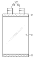
도 2는, 본 발명의 일 실시예에 따른 파우치형 이차 전지의 사시도이고, 도 3은, 도 2를 아래에서 바라본 도면이고, 도 4는, 도2의 A-A에 따른 개략적인 단면도이다. FIG. 2 is a perspective view of a pouch type secondary battery according to an embodiment of the present invention. FIG. 3 is a plan view of FIG. 2, and FIG. 4 is a schematic cross-sectional view of FIG.
이들 도면에 도시된 바와 같이, 본 발명에 따른 파우치형 이차 전지는, 전극 조립체(110, 도 7 참조)와, 전극 리드(120)와, 파우치 외장재를 포함한다. As shown in these drawings, the pouch type secondary battery according to the present invention includes an electrode assembly (110, see Fig. 7), an
여기서 파우치 외장재는, 중앙 영역이 판상형인 상부 파우치(131)와, 중앙 영역에 전극 조립체(110)를 수용하는 공간을 형성하는 하부 파우치(132)를 구비하며, 상부 파우치(131)와 하부 파우치(132)의 가장자리에 실링부(S)를 구비하여 밀폐된다. 그리고 상기 실링부(S)는, 적어도 일측이 절곡 또는 굴곡되어 상기 상부 파우치(131)의 상부, 즉 상부 파우치(131)의 상면(U) 위쪽에 배치되도록 폴딩된 형태를 가질 수 있다. Here, the pouch exterior member includes an
전극 조립체(110, 도 7 참조)는, 도면의 편의상 자세히 도시하지 않았으나, 양극판, 음극판, 세퍼레이터 및 전극 탭을 포함한다. 전극 조립체(110)는 적층된 양극판 및 음극판 사이에 세퍼레이터를 개재하여 형성된 적층형이거나, 하나의 양극판 및 하나의 음극판을 세퍼레이터를 사이에 두고 권취시킨 젤리-롤(jelly-roll) 타입일 수 있다. 물론, 본 발명의 권리범위가 이러한 전극 조립체(110)의 형태에 한정되어야 하는 것은 아니다. 양극판은 알루미늄(Al) 재질의 집전판에 양극 활물질이 도포되어 형성되며, 음극판은 구리(Cu) 재질의 집전판에 음극 활물질이 도포되어 형성될 수 있다. 전극 탭은 양극판 중 양극 활물질이 도포되지 않은 영역에 해당하는 양극 탭 및 음극 판 중 음극 활물질이 도포되지 않은 영역에 해당하는 음극 탭을 포함한다.The electrode assembly 110 (see Fig. 7) includes a positive electrode plate, a negative electrode plate, a separator, and an electrode tab, although not shown in detail for the sake of convenience of illustration. The
전극 리드(120)는, 얇은 판상의 금속으로서 전극 탭에 부착되어 전극 조립체(110)의 외측 방향으로 연장된다. 전극 리드(120)는 양극 탭에 부착되는 양극 리드(121) 및 음극 탭에 부착되는 음극 리드(122)를 포함한다. The
이러한 양극 리드(121) 및 음극 리드(122)는 양극 탭 및 음극 탭의 형성 위치에 따라 서로 다른 방향으로 연장될 수도 있고, 서로 동일한 방향(도 2 참조)으로 연장될 수도 있다.The
파우치 외장재(130)는, 내부 공간에 전극 조립체(110) 및 전해액을 수납한다. 특히, 파우치 외장재(130)는 폴리머 재질의 외부 절연층과 내부 접착층, 그리고 외부 절연층과 내부 접착층 사이에 개재된 금속층을 구비할 수 있다. 여기서, 금속층의 재질로는 알루미늄(Al)이 이용될 수 있다.The
이러한 파우치 외장재(130)는, 전극 조립체(110)와 전해액 등 내부 구성요소를 보호하고, 전극 조립체(110)와 전해액에 의한 전기 화학적 성질에 대한 보완 및 방열 기능을 수행한다. The
본 실시예에 따른 파우치 외장재(130)는, 도 2 내지 도 4을 참조하면, 상부 파우치(131)와, 상부 파우치(131)와 상호 접착되는 하부 파우치(132)로 구성될 수 있다.2 to 4, the
상부 파우치(131)는 전체적으로 판상형으로 마련되고 하부 파우치(132)는 전극 조립체(110)가 수납될 수 있도록 중앙 영역이 오목하게 형성된다. 여기서 하부 파우치(132)의 오목한 공간은 전극 조립체(110)의 높이와 너비에 대응되게 형성될 수 있다. 그리고 상부 파우치(131)와 하부 파우치(132)의 가장자리에는 열융착되어 상호 실링되는 실링부(S)가 위치한다. The
이하에서는 이러한 파우치 외장재(130)의 실링부(S)에 대해 자세히 설명하기로 한다. 설명에 앞서, 본 실시예에 따른 파우치형 이차 전지(100)의 방향성에 대한 기준을 정하기로 한다. 도 2를 참조하여, 전극 리드(120)가 노출되는 부분(변)을 파우치형 이차 전지(100)의 전면부(F), 전면부(F)와 좌,우로 이웃하는 부분(변)을 각각 파우치형 이차 전지(100)의 좌측면부(L)와 우측면부(R), 전면부(F)와 반대 방향에 위치한 부분(변)을 파우치형 이차 전지(100)의 후면부(RE)로 정의한다. 그리고 상부 파우치(131)의 외측면(U)을 파우치형 이차 전지(100)의 상면(U), 상부 파우치(131)와 나란한 하부 파우치(132)의 외측면을 파우치형 이차 전지(100)의 하면(D)으로 정의한다. Hereinafter, the sealing portion S of the
물론, 본 실시예에서 전, 후, 좌, 우, 상, 하와 같은 방향을 나타내는 용어가 사용되었으나, 이러한 용어들은 설명의 편의를 위한 것일 뿐, 대상이 되는 사물의 위치나 관측자의 위치 등에 따라 달라질 수 있다.Of course, in the present embodiment, terms indicating directions such as front, back, left, right, top, and bottom are used, but these terms are for convenience of explanation only and vary depending on the position of the object or the position of the observer .
도 2 및 도 3에 도시된 바와 같이, 본 실시예에 따른 실링부(S)는 파우치형 이차 전지(100)의 전면부(F)에 위치하는 전면실링부(S1)와, 전면실링부(S1)와 상호 이웃하고 상부 파우치(131)의 외측면(U)에 나란하게 위치하는 상면배치실링부(S2)와, 파우치형 이차 전지(100)의 후면부(RE)에 위치하는 후면실링부(S3)를 포함한다. 2 and 3, the sealing portion S according to the present embodiment includes a front sealing portion S1 located on the front portion F of the pouch type
보다 구체적으로 설명하면, 전면실링부(S1)는 파우치형 이차 전지(100)의 전면부(F)에서 외측으로 연장되어 있는 부분으로, 전극 리드(120)가 그 사이를 통해 외부로 노출될 수 있다. More specifically, the front sealing portion S1 is a portion extending outward from the front portion F of the pouch type
후면실링부(S3)는 파우치형 이차 전지(100)의 후면부(RE)에서 외측으로 연장된 부분이다. 후면실링부(S3)는 동일 평면상에서 전면실링부(S1)의 반대측에 위치한다. 그러나 필요에 따라 본 실시예와 달리, 후면실링부(S3)는 후술할 상면배치실링부(S2)와 같이, 절곡되어 상부 파우치(131)의 외측면(U)에 나란하게 배치될 수도 있다. The rear sealing portion S3 is a portion extending outward from the rear portion RE of the pouch type
본 실시예에 따른 상면배치실링부(S2)는 파우치형 이차 전지(100)의 상면(U), 즉 상부 파우치(131)의 외측면(U)에 나란하게 배치되어 있다. 특히, 상면배치실링부(S2)는, 전면실링부(S1) 및 후면실링부(S3)가 이차 전지(100)의 전면부(F)와 후면부(RE)에서 각각 외측으로 연장되어 있는 반면에, 이차 전지(100)의 좌측면부(L) 및 우측면부(R)에서 적어도 90도 각도 이상 절곡되어 있다. 따라서 본 발명의 파우치형 이차 전지(100)는, 도 3에 도시된 바와 같이, 전술한 종래 기술의 파우치형 이차 전지의 윙(wing)부분이 없는 것과 같아져 그 만큼 폭이 줄어들어 컴팩트(compact)해 질수 있다. The upper surface disposition sealing portion S2 according to the present embodiment is disposed in parallel to the upper surface U of the pouch type
부연 설명하면, 본 실시예에서 상부 파우치(131)와 하부 파우치(132)는 둘레방향을 따라 네 모서리를 갖는다. 하부 파우치(132)의 가장자리는 판상형인 상부 파우치(131)의 가장자리와 열융착되어 파우치 외장재(130)를 밀폐시키는 실링부(S)를 형성한다. 따라서 실링 직후의 실링부(S)는 전극 조립체(110)가 수납되어 있는 파우치 외장재의 중앙 영역에서 외측으로, 다시 말해, 파우치형 이차 전지(100)의 전면부(F), 후면부(RE), 좌측면부(L) 및 우측면부(R)에서 외측으로 벋어있는 상태가 된다. 그런데, 전술한 바와 같이, 이차 전지의 좌측면부(L) 및 우측면부(R)에서 외측으로 벋어있는 실링부(S)는 파우치형 이차 전지(100)에 있어서 불필요한 공간인 데드 스페이스(dead space)가 된다. 또한, 이러한 경우 전술한 바와 같이, 열 전달 측면에서도 구조적으로 바람직하지 못하게 된다. 하지만, 본 발명의 파우치형 이차 전지(100)는 상술한 바와 같이, 상부 파우치(131)와 하부 파우치(132)의 열융착 후에 상면배치실링부(S2)를 파우치형 이차 전지의 좌측면부(L) 및 우측면부(R)에서 적어도 180도 절곡시켜 상면배치실링부(S2)가 상부 파우치(131)의 외측면에 나란하게 접힌 형태를 갖도록 마련된다. In other words, in the present embodiment, the
한편, 본 발명에 따른 상면배치실링부(S2)는 적어도 2회이상 절곡된 형상을 가질 수 있다. 도4를 참조하여 구체적으로 설명하면, 상면배치실링부(S2)는 대략 절반이 먼저 접힌 상태에서 다시 180도 접혀 상부 파우치(131)의 외측면(U)에 나란하게 배치될 수 있다. Meanwhile, the top surface sealing part S2 according to the present invention may have a shape bent at least twice. 4, the upper surface disposition sealing portion S2 may be arranged in parallel with the outer surface U of the
일반적으로 종래 기술의 실링부는 밀폐력이 약화되면 실링부에 틈이 벌어져 전해액이 그 틈새로 유입되거나 외부에서 파우치 외장재(130) 내부로 수분 침투율이 높아질 수 있다. 하지만 본 실시예에 따른 상면배치실링부(S2)는 경로(pass)가 보다 복잡하고 끝단부가 외부에 노출되어 있지 않아 전해액 누액이나 외부의 수분 침투율을 저하시킬 수 있는 이점이 있다. Generally, when the sealing force of the sealing part of the prior art is weakened, a gap may be formed in the sealing part, so that the electrolytic solution may flow into the gap or the permeation rate of moisture from the outside into the inside of the
그러나, 본 발명의 권리범위가 이러한 실시예에 한정되는 것은 아니다. 즉, 상면배치실링부(S2)는 1회 또는 3회 이상 절곡된 형상을 갖거나 소정의 곡률을 갖는 굴곡된 형상을 가질 수도 있을 것이다. 즉, 굴곡된 형상을 갖는 상면배치실링부는 전술한 2회이상 절곡된 형상의 상면배치실링부(S2) 보다는 수분 침투 저지 효율이 낮을 수 있으나 그 가공 공정이 간소화되는 이점이 있을 수 있다. However, the scope of the present invention is not limited to these embodiments. That is, the top-surface-arranging sealing portion S2 may have a bent shape once or three or more times, or may have a bent shape having a predetermined curvature. In other words, the upper surface disposition sealing portion having a curved shape may have a lower water permeation blocking efficiency than the upper surface disposition sealing portion S2 having the above-mentioned two-fold folded shape, but may be advantageous in that the processing process is simplified.
또한 본 실시예에 따른 상면배치실링부(S2)는 외력에 의해 상부 파우치(131)의 외측면(U)에서 떨어지지 않도록 실런트(sealent)등의 접착부재로 상부 파우치(131)의 외측면(U)에 접착될 수 있다. 이러한 상면배치실링부(S2)는 들뜨지 않아 차후에 본 발명의 파우치형 이차 전지(100)의 형상에 맞춤 제작된 카트리지 내지는 프레임틀에 손쉽게 장착할 수 있는 이점이 있을 수 있다. The top surface positioning sealing portion S2 according to the present embodiment is formed by an adhesive member such as a sealant so as not to be separated from the outer surface U of the
이와 같은 본 발명의 파우치형 이차 전지(100)는 종래 보다 컴팩트(compact)한 구조를 가질 수 있으며, 이러한 파우치형 이차 전지(100)를 다수를 포함하는 배터리 모듈의 크기도 종래 보다 컴팩트(compact)해 질 수 있다.The pouch type
또한, 본 발명에 따른 파우치형 이차 전지(100)는 종래보다 우수한 냉각효율을 가질 수 있다. 이하에서는 도 5 및 도 6을 참조하여 이에 대해 간략히 설명하기로 한다. In addition, the pouch type
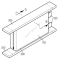
본 발명에 따른 파우치형 이차 전지(100)는 하나 또는 두 개 이상이 카트리지(200)에 수용될 수 있다. 도면의 편의상 자세히 도시하지는 않았으나, 카트리지(200)는 파우치형 이차 전지(100)가 안착되도록 하여 이를 홀딩하고 그 유동을 방지하며, 상호 적층 가능하도록 하는 구성될 수 있다. One or more of the pouch type
한편, 파우치형 이차 전지(100)의 좌측면부(L) 및/또는 우측면부(R)에는 파우치형 이차 전지(100)와 열 교환 할수 있는 냉각부재(300)가 인접하게 마련될 수 있다. 이러한 냉각부재(300)로는 이차 전지(100)의 열을 외부 전달하는 냉각핀, 히트 싱크(hit sink) 및/또는 냉각채널이 적용될 수 있을 것이다. 냉각채널은 냉각공기 또는 냉각수의 유로를 형성하는 덕트일 수 있다. The pouch type
도 5 및 도6을 참조하면, 카트리지(200)와 접하는 냉각핀을 냉매를 통해 냉각 시킴으로써 파우치형 이차 전지(100)에서 발생한 열이 냉각핀을 통해 전달되며, 냉각핀은 다시 냉매에게 열을 전달할 수 있다. 여기서 냉각핀에는 냉매와 빠른 열 교환을 위해 히트싱크(heat sink)가 형성될 수 있다. 5 and 6, by cooling the cooling fins in contact with the
특히, 본 실시예와 같은 간접 냉각 방식에 있어서는 파우치형 배터리 셀 내부의 열이 파우치형 이차 전지(100)의 좌측면부(L) 및/또는 우측면부(R)를 통해 빠져나가게 된다. 이때 본 발며의 경우 전극 조립체(110)로부터 냉각부재로 열이 빠져나가는 경로에, 좌측면부(L) 및/또는 우측면부(R)의 실링부가 개재되어 있지 않기 때문에 이로 인한 열 전달이 방해받는 문제가 발생하지 않아 종래에 비해 외부로 열 전달이 보다 효과적으로 이루어 질 수 있다. Particularly, in the indirect cooling method as in the present embodiment, the heat inside the pouch-shaped battery cell exits through the left side surface portion L and / or the right side surface portion R of the pouch type
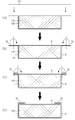
도 7은 본 발명의 일 실시예에 따른 파우치형 이차 전지의 제조 과정을 설명하기 위한 개략적인 도면이다. FIG. 7 is a schematic view illustrating a manufacturing process of a pouch type secondary battery according to an embodiment of the present invention. Referring to FIG.
이하에서는 도 7을 참조하여 본 발명의 파우치형 이차 전지의 제조방법에 대해 설명하기로 한다. Hereinafter, a method of manufacturing the pouch type secondary battery of the present invention will be described with reference to FIG.
본 발명의 파우치형 이차 전지(100)의 제조방법은, 전극 조립체(110)의 수납공간이 형성되도록 하부 파우치(132)와, 하부 파우치(132)와 가장자리 영역이 열융착되는 판상형의 상부 파우치(131)를 준비하는 단계와, 전극 조립체(110)와 연결되는 전극 리드(120)는 외부에 노출되며, 전극 조립체(110)는 내부에 수용되게 하부 파우치(132)와 상부 파우치(131)의 가장자리에 형성된 실링부(S)를 실링(sealing)하는 실링단계와, 상기 실링부(S) 중에서 적어도 일측부를 상부 파우치(131)의 상면(U)으로 폴딩 (folding)시키는 폴딩단계를 포함할 수 있다.A method of manufacturing a pouch type
본 실시예에서 실링(sealing)단계는 직사각형태의 테두리를 갖는 상부 파우치(131)와 하부 파우치(132)의 네 모서리를 얼라인(align)시킨 다음, 이들을 서로 합착시키는 방식으로 진행된다. 이때 실링부(S)는 실링부(S)의 내주면에 열 접착층이 있어 열 및 압력에 의해 접착될 수 있다. In the present embodiment, the sealing step is performed in such a manner that four corners of the
폴딩단계는, 실링부(S) 중에서 적어도 일측부를 적어도 2회이상 절곡시키는 단계를 포함한다. 본 실시예에서 실링부(S)는 상술한 바와 같이, 전면실링부(S1)와 후면실링부(S3) 및 상면배치실링부(S2)를 포함하는데, 실링단계를 마치면 상면배치실링부(S2)가 폴딩(folding) 대상이 된다. 먼저, 도 7의 (b)에 도시된 바와 같이, 상면배치실링부(S2)를 가상의 라인인 L1을 축으로 180도 폴딩시킨다. 그 다음, 도 7의 (c)에 도시된 바와 같이, 1단으로 접혀 있는 상면배치실링부를 가상의 라인인 L2를 축으로 180도 폴딩시켜 상면배치실링부(S2) 전체가 상부 파우치(131)의 외측면(U)에 나란하게 위치할 수 있도록 한다. 참고로, 폴딩단계를 수행하는 주요한 목적은 상면배치실링부(S2)가 파우치형 이차 전지(100)의 좌측면부(L) 및/또는 우측면부(R) 밖으로 돌출되지 않도록 하기 위함으로 반드시 본 실시예와 같은 방식에 한정되어 폴딩되어야 하는 것은 아니다. 또한, 상면배치실링부(S2)는 소정의 곡률 반경으로 상부 파우치(131) 외측면(U)으로 휘어지거나 구부러지게 배치될 수 있다. The folding step includes bending at least one side of the sealing portion (S) at least twice. In the present embodiment, the sealing portion S includes the front sealing portion S1, the rear sealing portion S3, and the top surface positioning sealing portion S2 as described above. When the sealing step S is completed, the top surface positioning sealing portion S2 ) Is subjected to folding. First, as shown in Fig. 7 (b), the upper surface disposition sealing portion S2 is folded 180 degrees along the imaginary line L1. Then, as shown in FIG. 7 (c), the top surface disposition sealing portion S2 is folded 180 degrees along the imaginary line L2 by 180 degrees so that the entire upper surface disposition sealing portion S2 is folded over the
그리고 필요에 따라서, 본 발명의 파우치형 이차 전지(100) 제조방법은, 상면배치실링부(S2)를 상부 파우치(131)의 외측면(U)에 대해 들뜨지 않도록 상부 파우치(131)의 외측면(U)에 실런트(sealent)등의 접착제로 접착시키는 접착단계를 더 포함할 수도 있다. The method for manufacturing the pouch type
한편, 본 발명에 따른 배터리 팩은, 상술한 본 발명에 따른 파우치형 이차 전지(100)를 둘 이상 포함할 수 있다. 특히, 본 발명에 따른 배터리 팩은, 상술한 본 발명에 따른 배터리 모듈을 하나 이상 포함할 수 있다. 또한, 배터리 팩은, 이러한 배터리 모듈 이외에도, 이러한 배터리 모듈을 커버하기 위한 케이스, 배터리 모듈의 충방전을 제어하기 위한 각종 장치, 이를테면 BMS, 전류 센서, 퓨즈 등이 더 포함될 수 있다. Meanwhile, the battery pack according to the present invention may include two or more pouch type
예컨데, 본 발명에 따른 파우치형 이차 전지(100), 특히 본 발명에 따른 배터리 모듈은, 전기 자동차나 하이브리드 자동차와 같은 자동차 및 IT 제품군 등에 적용될 수 있다. For example, the pouch type
이와 같이 본 발명은 기재된 실시예에 한정되는 것이 아니고, 본 발명의 사상 및 범위를 벗어나지 않고 다양하게 수정 및 변형할 수 있음은 이 기술의 분야에서 통상의 지식을 가진 자에게 자명하다. 따라서 그러한 수정예 또는 변형예들은 본 발명의 특허청구범위에 속한다 하여야 할 것이다.It will be apparent to those skilled in the art that various modifications and variations can be made in the present invention without departing from the spirit or scope of the invention. Accordingly, such modifications or variations are intended to fall within the scope of the appended claims.
100: 파우치형 이차 전지
110: 전극 조립체
120: 전극 리드
130: 파우치 외장재
131: 상부 파우치
132: 하부 파우치
S : 실링부
S1 : 전면실링부
S2 : 상면배치실링부100: Pouch type secondary battery
110: electrode assembly
120: electrode lead
130: Pouch Exterior Material
131: upper pouch
132: Lower pouch
S: sealing part
S1: Front sealing part
S2: upper surface positioning sealing portion
Claims (11)
상기 전극 조립체와 연결되는 전극 리드; 및
판상형인 상부 파우치와, 중앙 영역에 상기 전극 조립체를 수용하는 공간을 형성하는 하부 파우치를 구비하며, 상기 상부 파우치와 상기 하부 파우치의 가장자리에 실링부를 구비하여 밀폐되는 파우치 외장재를 포함하며,
상기 실링부는,
적어도 일측이 상기 상부 파우치의 상부로 폴딩된 상면배치실링부를 구비하는 것을 특징으로 하는 파우치형 이차 전지.An electrode assembly;
An electrode lead connected to the electrode assembly; And
And a pouch outer case having a sealing pouch at an edge of the upper pouch and the lower pouch, wherein the upper pouch has a plate-shaped upper pouch and a lower pouch for forming a space for accommodating the electrode assembly in a central area,
The sealing portion
Wherein at least one side of the upper pouch is provided with a top surface disposing sealing part folded on the upper side of the upper pouch.
상기 상면배치실링부는,
상기 실링부 중에서 상기 전극 리드가 노출되지 않는 상기 파우치 외장재의 양측면 가장자리 부분이 상기 상부 파우치의 상부로 폴딩되어 형성된 것을 특징으로 하는 파우치형 이차 전지. The method according to claim 1,
The upper surface-
Wherein both side edge portions of the pouch exterior member, from which the electrode leads are not exposed, of the sealing portions are folded to the upper portion of the upper pouch.
상기 상면배치실링부는,
상기 상부 파우치의 상면에 나란하게 접촉배치되는 것을 특징으로 하는 파우치형 이차 전지. 3. The method of claim 2,
The upper surface-
Wherein the upper and lower pouches are disposed in parallel with each other on the upper surface of the upper pouch.
상기 상면배치실링부는,
적어도 2회이상 절곡된 형상을 갖는 것을 특징으로 하는 파우치형 이차 전지.The method of claim 3,
The upper surface-
Wherein the pouch type secondary battery has a shape bent at least twice.
상기 상면배치실링부는,
상기 상부 파우치의 상면으로 소정의 곡률 반경을 가지는 굴곡된 형상을 갖는 것을 특징으로 하는 파우치형 이차 전지.The method of claim 3,
The upper surface-
And a curved shape having a predetermined curvature radius on an upper surface of the upper pouch.
상기 상면배치실링부는,
상기 상부 파우치의 상면에 접착되는 것을 특징으로 하는 파우치형 이차 전지.3. The method of claim 2,
The upper surface-
Wherein the upper and lower pouches are bonded to the upper surface of the upper pouch.
상기 하부 파우치의 수납공간에 전극 리드가 외부에 노출되도록 상기 전극 조립체를 수납하는 단계;
상기 하부 파우치와 상기 상부 파우치의 가장자리에 형성된 실링부를 실링(sealing)하는 단계; 및
상기 실링부 중에서 적어도 일측부를 상기 상부 파우치의 상부로 폴딩시키는 단계를 포함하는 것을 특징으로 하는 파우치형 이차 전지 제조방법.Preparing a lower pouch having a storage space for the electrode assembly and a plate-shaped upper pouch;
Storing the electrode assembly in an accommodating space of the lower pouch so that an electrode lead is exposed to the outside;
Sealing the lower pouch and the sealing portion formed at the edge of the upper pouch; And
And folding at least one of the sealing portions to an upper portion of the upper pouch.
상기 폴딩단계는, 상기 실링부 중에서 적어도 일측부를 적어도 2회이상 절곡시키는 것을 특징으로 하는 파우치형 이차 전지 제조방법.9. The method of claim 8,
Wherein the folding step comprises bending at least one side of the sealing part at least twice.
상기 폴딩단계는, 상기 실링부 중에서 적어도 일측부를 상기 상부 파우치의 상면에 나란하게 접촉배치시키는 것을 포함하는 것을 특징으로 하는 파우치형 이차 전지 제조방법.9. The method of claim 8,
Wherein the folding step comprises placing at least one side of the sealing parts in contact with the upper surface of the upper pouch in parallel.
상기 폴딩단계는, 상기 실링부 중에서 적어도 일측부를 상기 상부 파우치의 상면에 접착시키는 것을 포함하는 것을 특징으로 하는 파우치형 배터리 셀 제조방법.11. The method of claim 10,
Wherein the folding step comprises bonding at least one side of the sealing portion to the upper surface of the upper pouch.
Priority Applications (1)
| Application Number | Priority Date | Filing Date | Title |
|---|---|---|---|
| KR1020140135178A KR20160041402A (en) | 2014-10-07 | 2014-10-07 | Pouch type secondary battery and a method of making the same |
Applications Claiming Priority (1)
| Application Number | Priority Date | Filing Date | Title |
|---|---|---|---|
| KR1020140135178A KR20160041402A (en) | 2014-10-07 | 2014-10-07 | Pouch type secondary battery and a method of making the same |
Publications (1)
| Publication Number | Publication Date |
|---|---|
| KR20160041402A true KR20160041402A (en) | 2016-04-18 |
Family
ID=55916523
Family Applications (1)
| Application Number | Title | Priority Date | Filing Date |
|---|---|---|---|
| KR1020140135178A Ceased KR20160041402A (en) | 2014-10-07 | 2014-10-07 | Pouch type secondary battery and a method of making the same |
Country Status (1)
| Country | Link |
|---|---|
| KR (1) | KR20160041402A (en) |
Cited By (13)
| Publication number | Priority date | Publication date | Assignee | Title |
|---|---|---|---|---|
| KR20170121490A (en) * | 2016-04-25 | 2017-11-02 | 주식회사 엘지화학 | Secondary battery and manufacturing method for the same |
| WO2017209371A1 (en) * | 2016-05-31 | 2017-12-07 | 주식회사 엘지화학 | Battery cell including phase change material |
| KR20200012205A (en) * | 2018-07-26 | 2020-02-05 | 주식회사 엘지화학 | Pouch and secondary battery |
| WO2021215661A1 (en) * | 2020-04-22 | 2021-10-28 | 주식회사 엘지에너지솔루션 | Battery module and manufacturing method thereof |
| WO2021233898A1 (en) | 2020-05-19 | 2021-11-25 | Saft | Electrochemical element and corresponding battery |
| US11196117B2 (en) | 2017-12-21 | 2021-12-07 | Lg Chem, Ltd. | Apparatus for sealing pouch case |
| KR20210155466A (en) | 2020-06-16 | 2021-12-23 | 윤정헌 | Luminaire with variable floodlight pattern |
| CN113937402A (en) * | 2020-07-14 | 2022-01-14 | Sk新技术株式会社 | Pouch-shaped case, secondary battery having the same, method of manufacturing the same, and secondary battery module |
| US11233279B2 (en) | 2017-12-04 | 2022-01-25 | Samsung Sdi Co., Ltd. | Battery pack |
| KR20220114972A (en) * | 2021-02-09 | 2022-08-17 | 주식회사 클레버 | Device for aligning pouch type secondary battery |
| WO2022243243A1 (en) | 2021-05-18 | 2022-11-24 | Saft | Electrochemical element for a battery, and corresponding battery |
| CN115425338A (en) * | 2016-12-20 | 2022-12-02 | Sk新能源株式会社 | Pouch type secondary battery and method of manufacturing the same |
| US12506172B2 (en) | 2016-12-20 | 2025-12-23 | Sk On Co., Ltd. | Pouch secondary battery and method of fabricating the same |
-
2014
- 2014-10-07 KR KR1020140135178A patent/KR20160041402A/en not_active Ceased
Cited By (24)
| Publication number | Priority date | Publication date | Assignee | Title |
|---|---|---|---|---|
| KR20170121490A (en) * | 2016-04-25 | 2017-11-02 | 주식회사 엘지화학 | Secondary battery and manufacturing method for the same |
| US10547092B2 (en) | 2016-05-31 | 2020-01-28 | Lg Chem, Ltd. | Battery cell including phase change material |
| KR20170135490A (en) * | 2016-05-31 | 2017-12-08 | 주식회사 엘지화학 | Battery Cell Including Phase Change Material |
| WO2017209371A1 (en) * | 2016-05-31 | 2017-12-07 | 주식회사 엘지화학 | Battery cell including phase change material |
| CN115425338A (en) * | 2016-12-20 | 2022-12-02 | Sk新能源株式会社 | Pouch type secondary battery and method of manufacturing the same |
| CN115425338B (en) * | 2016-12-20 | 2024-05-24 | Sk新能源株式会社 | Pouch type secondary battery and method for manufacturing the same |
| US12506172B2 (en) | 2016-12-20 | 2025-12-23 | Sk On Co., Ltd. | Pouch secondary battery and method of fabricating the same |
| US11233279B2 (en) | 2017-12-04 | 2022-01-25 | Samsung Sdi Co., Ltd. | Battery pack |
| US11196117B2 (en) | 2017-12-21 | 2021-12-07 | Lg Chem, Ltd. | Apparatus for sealing pouch case |
| KR20200012205A (en) * | 2018-07-26 | 2020-02-05 | 주식회사 엘지화학 | Pouch and secondary battery |
| EP4645527A3 (en) * | 2020-04-22 | 2025-11-12 | LG Energy Solution, Ltd. | Battery module and manufacturing method thereof |
| US12294069B2 (en) * | 2020-04-22 | 2025-05-06 | Lg Energy Solution, Ltd. | Battery module and manufacturing method thereof |
| WO2021215661A1 (en) * | 2020-04-22 | 2021-10-28 | 주식회사 엘지에너지솔루션 | Battery module and manufacturing method thereof |
| EP4009427A4 (en) * | 2020-04-22 | 2024-06-12 | Lg Energy Solution, Ltd. | BATTERY MODULE AND ITS MANUFACTURING METHOD |
| US20220407138A1 (en) * | 2020-04-22 | 2022-12-22 | Lg Energy Solution, Ltd. | Battery Module and Manufacturing Method Thereof |
| WO2021233898A1 (en) | 2020-05-19 | 2021-11-25 | Saft | Electrochemical element and corresponding battery |
| US12476336B2 (en) | 2020-05-19 | 2025-11-18 | Saft | Electrochemical element and corresponding battery |
| FR3110771A1 (en) | 2020-05-19 | 2021-11-26 | Saft | Electrochemical element and corresponding battery |
| KR20210155466A (en) | 2020-06-16 | 2021-12-23 | 윤정헌 | Luminaire with variable floodlight pattern |
| CN113937402A (en) * | 2020-07-14 | 2022-01-14 | Sk新技术株式会社 | Pouch-shaped case, secondary battery having the same, method of manufacturing the same, and secondary battery module |
| CN113937402B (en) * | 2020-07-14 | 2025-11-28 | Sk新能源株式会社 | Pouch case, secondary battery having the same, method of manufacturing the same, and secondary battery module |
| KR20220114972A (en) * | 2021-02-09 | 2022-08-17 | 주식회사 클레버 | Device for aligning pouch type secondary battery |
| FR3123159A1 (en) | 2021-05-18 | 2022-11-25 | Saft | Electrochemical element for battery, and corresponding battery |
| WO2022243243A1 (en) | 2021-05-18 | 2022-11-24 | Saft | Electrochemical element for a battery, and corresponding battery |
Similar Documents
| Publication | Publication Date | Title |
|---|---|---|
| US10978759B2 (en) | Battery module having improved cooling performance | |
| KR101803958B1 (en) | A Battery Pack Case Having Efficient Cooling Structure | |
| US9865904B2 (en) | Battery cell of improved cooling efficiency | |
| US10224583B2 (en) | Secondary battery module having through type cool channel | |
| CN104603969B (en) | Battery module assembly and its manufacture method | |
| EP3285327B1 (en) | Battery module | |
| KR101615928B1 (en) | Middle or Large-sized Battery Pack Having Efficient Cooling Structure | |
| CN108431991B (en) | Battery pack including edge-cooled components | |
| KR101960922B1 (en) | Battery module | |
| EP4087018A1 (en) | Battery pack and device including same | |
| KR101543477B1 (en) | Battery module and lithium secondary battery pack comprising the same | |
| KR101481198B1 (en) | Battery module and lithium secondary battery pack comprising the same | |
| KR20220049870A (en) | Battery module and battery pack including the same | |
| KR20210130548A (en) | Battery module and battery pack including the same | |
| KR102085339B1 (en) | Battery Module improved heat conductive structure | |
| KR20160150514A (en) | Battery module | |
| KR102915625B1 (en) | Battery cell assembly with cooling fins and cooling tube | |
| KR20220144715A (en) | Battery module and battery pack including the same | |
| EP4376141A1 (en) | Battery module and battery pack including same | |
| CN115775941A (en) | Single battery and vehicle | |
| KR20210107472A (en) | Battery module and battery pack including the same |
Legal Events
| Date | Code | Title | Description |
|---|---|---|---|
| PA0109 | Patent application |
Patent event code: PA01091R01D Comment text: Patent Application Patent event date: 20141007 |
|
| A201 | Request for examination | ||
| PA0201 | Request for examination |
Patent event code: PA02012R01D Patent event date: 20151026 Comment text: Request for Examination of Application Patent event code: PA02011R01I Patent event date: 20141007 Comment text: Patent Application |
|
| PG1501 | Laying open of application | ||
| E902 | Notification of reason for refusal | ||
| PE0902 | Notice of grounds for rejection |
Comment text: Notification of reason for refusal Patent event date: 20170118 Patent event code: PE09021S01D |
|
| E601 | Decision to refuse application | ||
| PE0601 | Decision on rejection of patent |
Patent event date: 20170728 Comment text: Decision to Refuse Application Patent event code: PE06012S01D Patent event date: 20170118 Comment text: Notification of reason for refusal Patent event code: PE06011S01I |
|
| E601 | Decision to refuse application | ||
| E801 | Decision on dismissal of amendment | ||
| PE0601 | Decision on rejection of patent |
Patent event date: 20170918 Comment text: Decision to Refuse Application Patent event code: PE06012S01D Patent event date: 20170118 Comment text: Notification of reason for refusal Patent event code: PE06011S01I |
|
| PE0801 | Dismissal of amendment |
Patent event code: PE08012E01D Comment text: Decision on Dismissal of Amendment Patent event date: 20170918 Patent event code: PE08011R01I Comment text: Amendment to Specification, etc. Patent event date: 20170814 Patent event code: PE08011R01I Comment text: Amendment to Specification, etc. Patent event date: 20170316 |