KR20160042425A - Evaporated fuel processing device - Google Patents
Evaporated fuel processing device Download PDFInfo
- Publication number
- KR20160042425A KR20160042425A KR1020167004087A KR20167004087A KR20160042425A KR 20160042425 A KR20160042425 A KR 20160042425A KR 1020167004087 A KR1020167004087 A KR 1020167004087A KR 20167004087 A KR20167004087 A KR 20167004087A KR 20160042425 A KR20160042425 A KR 20160042425A
- Authority
- KR
- South Korea
- Prior art keywords
- valve seat
- liquid level
- valve
- fuel
- outlet port
- Prior art date
- Legal status (The legal status is an assumption and is not a legal conclusion. Google has not performed a legal analysis and makes no representation as to the accuracy of the status listed.)
- Granted
Links
Images

Classifications
-
- F—MECHANICAL ENGINEERING; LIGHTING; HEATING; WEAPONS; BLASTING
- F02—COMBUSTION ENGINES; HOT-GAS OR COMBUSTION-PRODUCT ENGINE PLANTS
- F02M—SUPPLYING COMBUSTION ENGINES IN GENERAL WITH COMBUSTIBLE MIXTURES OR CONSTITUENTS THEREOF
- F02M37/00—Apparatus or systems for feeding liquid fuel from storage containers to carburettors or fuel-injection apparatus; Arrangements for purifying liquid fuel specially adapted for, or arranged on, internal-combustion engines
- F02M37/0076—Details of the fuel feeding system related to the fuel tank
-
- B—PERFORMING OPERATIONS; TRANSPORTING
- B60—VEHICLES IN GENERAL
- B60K—ARRANGEMENT OR MOUNTING OF PROPULSION UNITS OR OF TRANSMISSIONS IN VEHICLES; ARRANGEMENT OR MOUNTING OF PLURAL DIVERSE PRIME-MOVERS IN VEHICLES; AUXILIARY DRIVES FOR VEHICLES; INSTRUMENTATION OR DASHBOARDS FOR VEHICLES; ARRANGEMENTS IN CONNECTION WITH COOLING, AIR INTAKE, GAS EXHAUST OR FUEL SUPPLY OF PROPULSION UNITS IN VEHICLES
- B60K15/00—Arrangement in connection with fuel supply of combustion engines or other fuel consuming energy converters, e.g. fuel cells; Mounting or construction of fuel tanks
- B60K15/03—Fuel tanks
- B60K15/035—Fuel tanks characterised by venting means
-
- B—PERFORMING OPERATIONS; TRANSPORTING
- B60—VEHICLES IN GENERAL
- B60K—ARRANGEMENT OR MOUNTING OF PROPULSION UNITS OR OF TRANSMISSIONS IN VEHICLES; ARRANGEMENT OR MOUNTING OF PLURAL DIVERSE PRIME-MOVERS IN VEHICLES; AUXILIARY DRIVES FOR VEHICLES; INSTRUMENTATION OR DASHBOARDS FOR VEHICLES; ARRANGEMENTS IN CONNECTION WITH COOLING, AIR INTAKE, GAS EXHAUST OR FUEL SUPPLY OF PROPULSION UNITS IN VEHICLES
- B60K15/00—Arrangement in connection with fuel supply of combustion engines or other fuel consuming energy converters, e.g. fuel cells; Mounting or construction of fuel tanks
- B60K15/03—Fuel tanks
- B60K15/035—Fuel tanks characterised by venting means
- B60K15/03519—Valve arrangements in the vent line
-
- F—MECHANICAL ENGINEERING; LIGHTING; HEATING; WEAPONS; BLASTING
- F02—COMBUSTION ENGINES; HOT-GAS OR COMBUSTION-PRODUCT ENGINE PLANTS
- F02M—SUPPLYING COMBUSTION ENGINES IN GENERAL WITH COMBUSTIBLE MIXTURES OR CONSTITUENTS THEREOF
- F02M25/00—Engine-pertinent apparatus for adding non-fuel substances or small quantities of secondary fuel to combustion-air, main fuel or fuel-air mixture
- F02M25/08—Engine-pertinent apparatus for adding non-fuel substances or small quantities of secondary fuel to combustion-air, main fuel or fuel-air mixture adding fuel vapours drawn from engine fuel reservoir
Landscapes
- Engineering & Computer Science (AREA)
- Chemical & Material Sciences (AREA)
- Combustion & Propulsion (AREA)
- Mechanical Engineering (AREA)
- General Engineering & Computer Science (AREA)
- Sustainable Development (AREA)
- Life Sciences & Earth Sciences (AREA)
- Sustainable Energy (AREA)
- Transportation (AREA)
- Cooling, Air Intake And Gas Exhaust, And Fuel Tank Arrangements In Propulsion Units (AREA)
- Supplying Secondary Fuel Or The Like To Fuel, Air Or Fuel-Air Mixtures (AREA)
- Self-Closing Valves And Venting Or Aerating Valves (AREA)
- Float Valves (AREA)
Abstract
급유 시에 풀탱크의 액면을 검지하여 캐니스터 연통 구멍(4)을 폐쇄하는 액면 검지 밸브(2)와, 액면이 풀탱크 시의 액면보다 높아졌을 때 증발 구멍(6)을 폐쇄하는 연료 차단 밸브(3)와, 캐니스터로 통하는 출구 포트(9)를 갖는 증발 연료 처리 장치(1)로서, 평면에서 볼 때, 제2 밸브 시트 상측부(12)와 제1 밸브 시트 상측부(11)를 연통시키는 제1 연통로(21)와, 제1 밸브 시트 상측부(11)와 출구 포트(9)를 연통시키는 제2 연통로(22)가, 제1 밸브 시트 상측부(11)를 경계로 하여 폴드백형으로 형성되어 있다. 이 구성에서는, 출구 포트(9)로부터의 연료의 액체 누설의 저감을 도모할 수 있다. A liquid level detecting valve 2 for detecting the liquid level of the full tank at the time of lubrication and closing the canister communication hole 4 and a fuel cutoff valve 2 for closing the evaporation hole 6 when the liquid level becomes higher than the liquid level at the full tank 3) and an outlet port (9) leading to a canister, wherein the first valve seat upper side portion (12) and the first valve seat upper side portion (11) communicate with each other The first communication passage 21 and the second communication passage 22 for communicating the first valve seat upper side portion 11 and the outlet port 9 communicate with each other through the first valve seat upper side portion 11, And is formed in a bag-like shape. With this configuration, it is possible to reduce the leakage of the fuel from the outlet port 9.
Description
본 발명은 연료 탱크의 증발 연료 처리 장치에 관한 것이다. The present invention relates to an evaporative fuel treatment apparatus for a fuel tank.
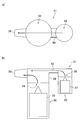
자동차 등의 연료 탱크에 부착되는 증발 연료 처리 장치의 종래예로서 특허문헌 1에 기재된 것을 들 수 있다. 도 3은 그 증발 연료 처리 장치를 모식화하여 나타낸 것이며, 도 3의 (a), (b)는 각각 평면도, 측면도이다. 증발 연료 처리 장치(31)는, 액면 검지 밸브(32) 및 연료 차단 밸브(33)를 구비한다. 액면 검지 밸브(32)는, 연료가 풀탱크(full tank) 상태가 되었을 때에 밸브 시트인 캐니스터 연통 구멍(34)을 폐쇄하는 제1 플로우트 밸브체(35)를 갖는다. 부호 L1(도 4)은 풀탱크 시의 액면을 나타내고 있다. 연료 차단 밸브(33)는, 예컨대 차체가 크게 기울어 액면이 풀탱크의 액면(L1)보다 높은 미리 정해진 위치까지 도달했을 때에 밸브 시트인 증발 구멍(36)을 폐쇄하는 제2 플로우트 밸브체(37)를 갖는다. 증발 구멍(36)은 캐니스터 연통 구멍(34)보다 상측에 위치하고 있다. As a prior art example of an evaporative fuel treatment apparatus attached to a fuel tank of an automobile or the like, those described in Patent Document 1 are listed. Fig. 3 is a schematic representation of the evaporative fuel treatment apparatus, and Figs. 3 (a) and 3 (b) are a plan view and a side view, respectively. The evaporation
제1 플로우트 밸브체(35) 및 제2 플로우트 밸브체(37)는, 그 밸브 박스로서 연료 탱크(T)에 부착되는 하우징(38)에 수용되어 있다. 하우징(38)에는, 도시하지 않은 캐니스터에 접속하는 출구 포트(39)가 형성되어 있다. 하우징(38) 내의 상부의 공간에 있어서, 캐니스터 연통 구멍(34)과 증발 구멍(36)은 연통로(40)를 통해 서로 연통해 있다. 증발 연료 처리 장치(31)는, 도 3의 (a)로부터 알 수 있듯이, 일단측으로부터 연료 차단 밸브(33), 액면 검지 밸브(32), 출구 포트(39)가 그 순서대로 일직선상에 레이아웃(layout)된 구조로 되어 있다. The first
종래의 증발 연료 처리 장치(31)는, 전술한 바와 같이 연료 차단 밸브(33), 액면 검지 밸브(32), 출구 포트(39)의 순서로 일직선상에 레이아웃되어 있기 때문에, 예컨대 언덕길 주차 등에서 차체가 기울어 도 4의 (b)에 나타낸 바와 같이 액면(부호 L2로 나타냄)이 하우징(38)에 대하여 경사진 형태로 되었을 때, 밸브 시트인 캐니스터 연통 구멍(34)이나 출구 포트(39)가 액면(L2)보다 하측에 위치하는 현상이 생기기 쉽다. 이때, 가령 캐니스터 연통 구멍(34)에서의 제1 플로우트 밸브체(35)의 밸브 폐쇄 기능에 지장이 생긴 경우, 액체의 연료가 캐니스터 연통 구멍(34)으로부터 스며나와 출구 포트(39)로부터 누설될 우려가 있다. Since the conventional evaporative
출구 포트(39)로부터의 누설을 회피하는 방법으로서, (1) 증발 구멍(36)의 위치를 캐니스터 연통 구멍(34)의 위치보다 낮추는 것, (2) 출구 포트(39)의 위치를 높게 하는 것 등이 고려된다. 그러나, (1)의 방법은, 풀탱크의 액면보다 높은 액면에서 기능하게 되는 연료 차단 밸브(33)의 구조상, 실질적으로 곤란하게 된다. 또한, (2)의 방법은, 하우징(38)의 높이 치수의 증대로 이어질 뿐만 아니라, 캐니스터 연통 구멍(34)으로부터의 누설의 문제는 여전히 남기 때문에, 그 누설된 연료가 차체의 요동 등에 의해 출구 포트(39)로 튀어서 누설될 우려가 있다. (1) lowering the position of the
본 발명은 이러한 과제를 해결하기 위해 창작된 것이며, 연료 탱크의 증발 연료 처리 장치에 있어서, 연료의 액체 누설의 저감을 도모하는 것을 목적으로 한다. An object of the present invention is to reduce the leakage of fuel in an evaporative fuel treatment system for a fuel tank.
상기 과제를 해결하기 위해, 본 발명은, 급유 시에 풀탱크의 액면을 검지하여 제1 밸브 시트를 폐쇄하는 액면 검지 밸브와, 액면이 풀탱크 시의 액면보다 높아졌을 때 제2 밸브 시트를 폐쇄하는 연료 차단 밸브와, 캐니스터로 통하는 출구 포트를 갖는 증발 연료 처리 장치로서, 평면에서 볼 때, 제2 밸브 시트 상측부와 제1 밸브 시트 상측부를 연통시키는 제1 연통로와, 제1 밸브 시트 상측부와 출구 포트를 연통시키는 제2 연통로가, 제1 밸브 시트 상측부를 경계로 하여 폴드백(fold back)형으로 형성되어 있는 것을 특징으로 한다. In order to solve the above problems, the present invention provides a liquid level detecting apparatus comprising: a liquid level detecting valve for detecting a liquid level of a full tank at the time of lubrication and closing a first valve seat; A first communication passage for communicating the upper portion of the second valve seat and the upper portion of the first valve seat in a plan view and a second communication passage for communicating the upper portion of the second valve seat with the upper portion of the first valve seat, And a second communication passage for communicating the side portion and the outlet port is formed in a foldback type with the upper portion of the first valve seat as a boundary.
본 발명에 의하면, 제1 밸브 시트 상측부를 경계로 하여 제1 연통로와 제2 연통로가 폴드백형으로 형성됨으로써, 일단측으로부터 액면 검지 밸브, 연료 차단 밸브, 출구 포트의 순서로, 혹은 액면 검지 밸브, 출구 포트, 연료 차단 밸브의 순서로 위치한다. 이 위치 관계에 의해, 제1 밸브 시트가 액체에 매몰되더라도 출구 포트에 관해서는 액체에 매몰되지 않도록 하는 레이아웃으로 할 수 있어, 출구 포트로부터의 연료의 액체 누설을 저감할 수 있다. According to the present invention, since the first communication path and the second communication path are formed in the foldback type with the upper portion of the first valve seat as a boundary, the liquid level detection valve, the fuel cutoff valve, The valve, the outlet port, and the fuel shutoff valve. With this positional relationship, even if the first valve seat is buried in the liquid, the outlet port can be arranged so as not to be buried in the liquid, so that leakage of the fuel from the outlet port can be reduced.
또한, 제1 밸브 시트 상측부를 경계로 하여 제1 연통로와 제2 연통로가 폴드백형으로 형성되어 있음으로써, 가령 제2 밸브 시트의 밸브 폐쇄 기능에 지장이 있어 제2 밸브 시트로부터 액체의 연료가 누출된 경우라 하더라도, 그 액체를 도중의 제1 밸브 시트 상측부에 떨어뜨릴 수 있어, 출구 포트로부터의 액체 누설을 방지할 수 있다. In addition, since the first communication path and the second communication path are formed in the foldback type with the upper portion of the first valve seat as a boundary, the valve closing function of the second valve seat is obstructed, It is possible to drop the liquid to the upper side portion of the first valve seat in the middle, so that leakage of the liquid from the outlet port can be prevented.
또한, 본 발명은, 상기 제1 밸브 시트 상측부를 통과하지 않고 상기 제2 밸브 시트 상측부와 상기 제2 연통로를 연통시키는 협소한 바이패스 유로를 구비하는 것을 특징으로 한다. Further, the present invention is characterized by a narrow bypass passage which does not pass through the upper portion of the first valve seat but communicates the upper portion of the second valve seat with the second communication passage.
본 발명에 의하면, 가령 제1 밸브 시트 상측부가 전부 액체에 매몰되어 제1 연통로와 제2 연통로가 비연통이 된 경우라 하더라도, 바이패스 유로를 통해 제2 밸브 시트 상측부 내의 증발 연료를 출구 포트로부터 밀어낼 수 있다. According to the present invention, even if the upper portion of the first valve seat is entirely buried in the liquid and the first communication path and the second communication path are non-communicating, the evaporation fuel in the upper portion of the second valve seat It can be pushed out of the outlet port.
본 발명에 의하면, 연료 탱크의 증발 연료 처리 장치에 있어서, 연료의 액체 누설의 저감을 도모할 수 있다. According to the present invention, it is possible to reduce the leakage of the liquid fuel in the evaporative fuel processing system of the fuel tank.
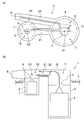
도 1은 본 발명에 따른 증발 연료 처리 장치의 설명도이며, (a), (b)는 각각 평면도, 측면도이다.
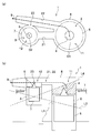
도 2는 본 발명에 따른 증발 연료 처리 장치에 대하여 연료의 액면이 경사진 경우의 설명도이며, (a), (b)는 각각 평면도, 측면도이다.
도 3은 종래의 증발 연료 처리 장치의 설명도이며, (a), (b)는 각각 평면도, 측면도이다.
도 4는 종래의 증발 연료 처리 장치에 대하여 연료의 액면이 경사진 경우의 설명도이며, (a), (b)는 각각 평면도, 측면도이다. 1 is an explanatory view of an evaporative fuel processing apparatus according to the present invention, wherein (a) and (b) are a plan view and a side view, respectively.
Fig. 2 is an explanatory view of a case where the liquid level of the fuel is inclined with respect to the evaporative fuel processing apparatus according to the present invention, wherein (a) and (b) are a plan view and a side view, respectively.
3 is an explanatory diagram of a conventional evaporative fuel treatment apparatus, wherein (a) and (b) are a plan view and a side view, respectively.
Fig. 4 is an explanatory view of a case where the liquid level of the fuel is inclined with respect to the conventional evaporative fuel treatment device, and Figs. 4A and 4B are a plan view and a side view, respectively.
도 1에 있어서, 본 실시형태의 증발 연료 처리 장치(1)는, 액면 검지 밸브(2)와 연료 차단 밸브(3)와 밸브 박스로서의 하우징(8)을 구비한다. 액면 검지 밸브(2)는, 급유 시에 풀탱크의 액면을 검지하여, 제1 밸브 시트인 캐니스터 연통 구멍(4)을 폐쇄하는 제1 플로우트 밸브체(5)를 갖는다. 구체적으로는, 급유 시에 연료의 액면이 미리 정해진 높이까지 상승하면, 하우징(8)의 개구부(도시하지 않음)가 연료로 막힘으로써 탱크 외부로의 유로가 끊어져 연료 탱크(T) 내의 압력이 상승한다. 이에 따라 연료가 하우징(8) 내에서 상승하고, 제1 플로우트 밸브체(5)가 캐니스터 연통 구멍(4)을 폐쇄한다. 캐니스터 연통 구멍(4)이 폐쇄됨으로써 연료 탱크 내의 압력은 더욱 상승하고, 연료가 필러 튜브(도시하지 않음)에서 상승하여 급유 노즐의 센서에 도달하면 급유의 오토스탑(auto stop)이 행해진다. 그리고, 하우징(8)의 오리피스(도시하지 않음)를 통해서 하우징(8) 내외의 기압차가 서서히 작아지고, 하우징(8) 내의 액면이 하강하여 제1 플로우트 밸브체(5)가 내려가고, 수회 정도의 추가 급유를 거쳐 풀탱크가 된다. 부호 L1(도 2)은 풀탱크 시의 액면을 나타내고 있다. 1, an evaporation fuel processing apparatus 1 of the present embodiment includes a liquid
연료 차단 밸브(3)는, 예컨대 차체가 크게 기울어 액면이 풀탱크 시의 액면(L1)보다 높은 미리 정해진 위치까지 도달했을 때에 제2 밸브 시트인 증발 구멍(6)을 폐쇄하는 제2 플로우트 밸브체(7)를 갖는다. 증발 구멍(6)은 캐니스터 연통 구멍(4)보다 상측에 위치하고 있다. 하우징(8)에는, 도시하지 않은 캐니스터에 접속하는 출구 포트(9)가 형성되어 있다. 출구 포트(9)는 캐니스터 연통 구멍(4)보다 상측에 위치하고 있다. 또한, 하우징(8) 내의 상부 공간으로서, 캐니스터 연통 구멍(4)의 상측에는 제1 밸브 시트 상측부(11)가 구획되고, 증발 구멍(6)의 상측에는 제2 밸브 시트 상측부(12)가 구획되어 있다. The
평면에서 볼 때, 제2 밸브 시트 상측부(12)와 제1 밸브 시트 상측부(11)를 연통시키는 제1 연통로(21)와, 제1 밸브 시트 상측부(11)와 출구 포트(9)를 연통시키는 제2 연통로(22)가, 제1 밸브 시트 상측부(11)를 경계로 하여 폴드백(fold back)형으로 형성되어 있다. 「폴드백형」이란, 액면 검지 밸브(2)의 축심(O1)과 연료 차단 밸브(3)의 축심(O2)을 연결하는 선분[본 실시형태에서는 제1 연통로(21)의 연장 방향]과 제2 연통로(22)의 연장 방향의 교차 각도 θ가 제로[즉 제1 연통로(21)와 제2 연통로(22)가 서로 평행한 경우] 또는 예각을 이루는 상태를 가리킨다. 그 관계에 의해, 제1 연통로(21)를 직교측면에서 본 상태에 있어서, 도 1의 (a)에 나타낸 바와 같이, 일단측으로부터 액면 검지 밸브(2), 연료 차단 밸브(3), 출구 포트(9)의 순서로, 혹은, 도시는 하지 않지만 일단측으로부터 액면 검지 밸브(2), 출구 포트(9), 연소 차단 밸브(3)의 순서로 위치한다. 종래에는 일단측으로부터 연료 차단 밸브, 액면 검지 밸브, 출구 포트의 순서로 위치했었다는 것은 전술한 바와 같다.A
또한, 본 실시형태의 증발 연료 처리 장치(1)는, 제1 밸브 시트 상측부(11)를 통과하지 않고 제2 밸브 시트 상측부(12)와 제2 연통로(22)를 연통하는 협소한 바이패스 유로(23)를 구비한다. 「협소」란, 바이패스 유로(23)의 유로 단면적이 제1 연통로(21) 및 제2 연통로(22)의 유로 단면적보다 작은 것을 의미한다. 바이패스 유로(23)는 예컨대 매우 작은 오리피스 구멍으로서 형성되며, 제2 밸브 시트 상측부(12)로부터 제2 연통로(22)로의 증발 연료의 통기는 허용하지만, 액체의 연료의 통과는 차단하는 기능을 담당한다. The evaporation fuel processing apparatus 1 according to the present embodiment is configured such that the first valve seat
「작용」 "Action"
차체가 그다지 기울지 않은 통상 시에는, 도 1에 나타낸 바와 같이 캐니스터 연통 구멍(4), 증발 구멍(6)이 모두 개방된 상태가 된다. 이에 따라, 연료 탱크(T) 내에서 발생한 증발 연료는, 캐니스터 연통 구멍(4)을 흐르는 증발 연료에 관해서는 제2 연통로(22)를 통과하여 출구 포트(9)로부터 캐니스터로 흐른다. 증발 구멍(6)을 흐르는 증발 연료에 관해서는, 제1 연통로(21) 및 제2 연통로(22)를 통과하고, 본 실시형태에서는 바이패스 유로(23)도 함께 통과하여 출구 포트(9)로부터 캐니스터로 흐른다. When the vehicle body is not tilted so much, the
다음으로, 언덕길 주차 등에서 차체가 크게 기울어, 도 2의 (b)에 나타낸 바와 같이 출구 포트(9)가 액면에 근접한 상태가 되었을 때[그 때의 액면을 부호 L3으로 나타냄], 액면 검지 밸브(2) 및 연료 차단 밸브(3)에 있어서 각각 캐니스터 연통 구멍(4), 증발 구멍(6)이 폐쇄된다. 이 상태에서는 증발 구멍(6)과 함께 캐니스터 연통 구멍(4)도 액면(L3)보다 상측에 위치하기 때문에, 캐니스터 연통 구멍(4)이 액체에 매몰되는 문제는 생기지 않는다. 또, 액면(L3)과 액면(L4)의 교점은 연료 차단 밸브(3)의 밸브 폐쇄 액위(-液位)이다.Next, when the vehicle body is largely inclined at the slope parking or the like and the
반대로 출구 포트(9)가 액면으로부터 멀어지는 상태가 되었을 때[그 때의 액면을 부호 L4로 나타냄], 액면 검지 밸브(2) 및 연료 차단 밸브(3)에 있어서 각각 캐니스터 연통 구멍(4), 증발 구멍(6)이 폐쇄된다. 이 상태에서는, 캐니스터 연통 구멍(4)이 증발 구멍(6)보다 하측에 형성되어 있기 때문에, 캐니스터 연통 구멍(4)이 액체에 매몰된다. 여기서, 종래에서는 도 4에 나타낸 바와 같이, 출구 포트(39)가 연료 차단 밸브(33)에 대하여 액면 검지 밸브(32)보다 더 떨어져 위치하고 있기 때문에, 액면(L2)에 의해 캐니스터 연통 구멍(34)이 액체에 매몰되면, 출구 포트(39)가 캐니스터 연통 구멍(34)보다 높은 위치에 형성되어 있더라도 출구 포트(39)도 액체에 매몰되기 쉽다는 문제가 있었다. Conversely, when the
이에 비해, 본 발명에서는, 전술한 바와 같이 제1 연통로(21)와 제2 연통로(22)가 제1 밸브 시트 상측부(11)를 경계로 하여 폴드백형으로 형성되어 있기 때문에, 일단측으로부터 액면 검지 밸브(2), 연료 차단 밸브(3), 출구 포트(9)의 순서로, 혹은 액면 검지 밸브(2), 출구 포트(9), 연료 차단 밸브(3)의 순서로 위치한다. 즉, 출구 포트(9)는 연료 차단 밸브(3)를 사이에 두고 액면 검지 밸브(2)와 반대측에 위치하거나, 혹은 액면 검지 밸브(2)보다 연료 차단 밸브(3)에 가까이 위치한다. 이에 따라 도 2의 (b)에 나타낸 바와 같이, 캐니스터 연통 구멍(4)이 액면(L4)에 액체 매몰되더라도 출구 포트(9)에 관해서는 액면(L4)에 액체 매몰되지 않도록 하는 레이아웃으로 할 수 있어, 출구 포트(9)로부터의 연료의 액체 누설을 줄일 수 있다. In contrast to this, in the present invention, since the
또한, 제1 연통로(21)와 제2 연통로(22)가 제1 밸브 시트 상측부(11)를 경계로 하여 폴드백형으로 형성되어 있음으로써 다음과 같은 효과도 발휘된다. 가령 증발 구멍(6)에서의 제2 플로우트 밸브체(7)의 밸브 폐쇄 기능에 지장이 생긴 경우에는 액체의 연료가 증발 구멍(6)으로부터 누설될 우려가 있다. 증발 구멍(6)의 형성 위치는 캐니스터 연통 구멍(4)에 비해 높고, 출구 포트(9)의 높이 위치에 가까운 경우도 있어, 만약에 제1 밸브 시트 상측부(11)를 통하지 않고 제2 밸브 시트 상측부(12)와 출구 포트(9)를 직접 연통시키면, 증발 구멍(6)으로부터 누설된 액체의 연료가 그대로 출구 포트(9)로부터 누설되기 쉬워진다. 이에 비해, 제1 밸브 시트 상측부(11)를 경계로 하여 제1 연통로(21)와 제2 연통로(22)를 폴드백형으로 형성함으로써, 증발 구멍(6)으로부터 누설된 액체의 연료를 제1 밸브 시트 상측부(11)에 떨어뜨릴 수 있어, 폴드백된 제2 연통로(22)에 대한 유출을 줄여서 출구 포트(9)로부터의 액체 누설을 방지할 수 있다. In addition, since the
또한, 본 실시형태에서는, 제1 밸브 시트 상측부(11)를 통과하지 않고 제2 밸브 시트 상측부(12)와 제2 연통로(22)를 연통시키는 협소한 바이패스 유로(23)를 구비하기 때문에, 제1 밸브 시트 상측부(11)가 전부 액체에 매몰되어 제1 연통로(21)와 제2 연통로(22)가 비연통이 된 경우라 하더라도, 바이패스 유로(23)를 통해서 제2 밸브 시트 상측부(12) 내의 증발 연료를 출구 포트(9)로부터 밀어낼 수 있다. In this embodiment, a
1 : 증발 연료 처리 장치
2 : 액면 검지 밸브
3 : 연료 차단 밸브
4 : 캐니스터 연통 구멍(제1 밸브 시트)
6 : 증발 구멍(제2 밸브 시트)
8 : 하우징
9 : 출구 포트
11 : 제1 밸브 시트 상측부
12 : 제2 밸브 시트 상측부
21 : 제1 연통로
22 : 제2 연통로
23 : 바이패스 유로1: Evaporative fuel treatment device
2: Liquid level detecting valve
3: Fuel shutoff valve
4: Canister communicating hole (first valve seat)
6: Evaporation hole (second valve seat)
8: Housing
9: Exit port
11: first valve seat upper side
12: second valve seat upper side
21: first communicating passage
22: second communicating passage
23: Bypass flow
Claims (2)
평면에서 볼 때, 제2 밸브 시트 상측부와 제1 밸브 시트 상측부를 연통시키는 제1 연통로와, 제1 밸브 시트 상측부와 출구 포트를 연통시키는 제2 연통로가, 제1 밸브 시트 상측부를 경계로 하여 폴드백(fold back)형으로 형성되어 있는 것을 특징으로 하는 증발 연료 처리 장치. A liquid level detecting valve that detects the liquid level of the full tank at the time of lubrication and closes the first valve seat, a fuel shutoff valve that closes the second valve seat when the liquid level becomes higher than the liquid level at the full tank, And an outlet port communicating with the evaporator,
A first communicating passage for communicating the upper portion of the second valve seat and the upper portion of the first valve seat in a plan view and a second communicating passage for communicating the upper portion of the first valve seat and the outlet port, Wherein the partition wall is formed in a fold back shape as a boundary.
상기 제1 밸브 시트 상측부를 통과하지 않고 상기 제2 밸브 시트 상측부와 상기 제2 연통로를 연통시키는 협소한 바이패스 유로
를 구비하는 것을 특징으로 하는 증발 연료 처리 장치.The method according to claim 1,
And a narrow bypass passage for communicating the upper portion of the second valve seat with the second communication passage without passing through the upper portion of the first valve seat,
And an evaporative fuel supply unit for supplying the evaporative fuel to the evaporative fuel supply unit.
Applications Claiming Priority (3)
| Application Number | Priority Date | Filing Date | Title |
|---|---|---|---|
| JP2013228204A JP6153850B2 (en) | 2013-11-01 | 2013-11-01 | Evaporative fuel processing equipment |
| JPJP-P-2013-228204 | 2013-11-01 | ||
| PCT/JP2014/075577 WO2015064253A1 (en) | 2013-11-01 | 2014-09-26 | Evaporated fuel processing device |
Publications (2)
| Publication Number | Publication Date |
|---|---|
| KR20160042425A true KR20160042425A (en) | 2016-04-19 |
| KR101868709B1 KR101868709B1 (en) | 2018-06-18 |
Family
ID=53003866
Family Applications (1)
| Application Number | Title | Priority Date | Filing Date |
|---|---|---|---|
| KR1020167004087A Active KR101868709B1 (en) | 2013-11-01 | 2014-09-26 | Evaporated fuel processing device |
Country Status (5)
| Country | Link |
|---|---|
| US (1) | US9995259B2 (en) |
| JP (1) | JP6153850B2 (en) |
| KR (1) | KR101868709B1 (en) |
| CN (1) | CN105683555B (en) |
| WO (1) | WO2015064253A1 (en) |
Cited By (2)
| Publication number | Priority date | Publication date | Assignee | Title |
|---|---|---|---|---|
| KR200483760Y1 (en) | 2017-01-10 | 2017-06-20 | 김성하 | Apparatus For Personal Washing Shaped Like Chair |
| KR200483980Y1 (en) | 2017-01-19 | 2017-07-18 | 김성하 | Wall-Hanging Apparatus For Personal Washing |
Citations (6)
| Publication number | Priority date | Publication date | Assignee | Title |
|---|---|---|---|---|
| JPH09112373A (en) * | 1995-10-13 | 1997-04-28 | Honda Motor Co Ltd | Evaporative fuel processing device |
| JP2000097120A (en) * | 1998-09-16 | 2000-04-04 | Nifco Inc | Fuel tank device |
| JP2001140717A (en) | 1999-11-12 | 2001-05-22 | Kyosan Denki Kk | Fuel vapor gas control device |
| JP2004068738A (en) * | 2002-08-08 | 2004-03-04 | Honda Motor Co Ltd | Evaporative fuel processing device |
| JP2004278314A (en) * | 2003-03-12 | 2004-10-07 | Honda Motor Co Ltd | Evaporative fuel processing device |
| JP2006097674A (en) * | 2004-08-30 | 2006-04-13 | Toyoda Gosei Co Ltd | Fuel cut-off valve |
Family Cites Families (30)
| Publication number | Priority date | Publication date | Assignee | Title |
|---|---|---|---|---|
| JPS5652088Y2 (en) * | 1975-05-29 | 1981-12-04 | ||
| JPS5357116U (en) * | 1976-10-19 | 1978-05-16 | ||
| JPH051645Y2 (en) * | 1987-02-02 | 1993-01-18 | ||
| US4782084A (en) | 1987-06-29 | 1988-11-01 | Merck & Co., Inc. | HMG-COA reductase inhibitors |
| JPS6426535U (en) * | 1987-08-10 | 1989-02-15 | ||
| JPH0250169U (en) * | 1988-09-30 | 1990-04-09 | ||
| JP2514397Y2 (en) * | 1989-01-31 | 1996-10-16 | 株式会社土屋製作所 | Fuel tank filler tube |
| JP2616599B2 (en) * | 1991-05-31 | 1997-06-04 | 日産自動車株式会社 | Fuel tank evaporative fuel treatment system |
| JPH07132740A (en) * | 1993-11-05 | 1995-05-23 | Toyoda Gosei Co Ltd | Fuel vapor processing device |
| JPH0972258A (en) * | 1995-09-05 | 1997-03-18 | Nissan Motor Co Ltd | Vapor discharge device for automobile fuel tank |
| US5687756A (en) * | 1995-11-08 | 1997-11-18 | Borg-Warner Automotive, Inc. | Vehicle refueling valve |
| JP3777214B2 (en) * | 1996-01-08 | 2006-05-24 | 株式会社ニフコ | Fuel spill prevention valve device |
| JPH10205634A (en) * | 1997-01-17 | 1998-08-04 | Nok Corp | Liquid cutoff valve device |
| JP3902694B2 (en) * | 1997-08-29 | 2007-04-11 | 富士重工業株式会社 | Fuel vapor emission prevention device |
| JP3914320B2 (en) * | 1998-01-26 | 2007-05-16 | 株式会社ミクニ | Fuel shut-off device and connecting structure of the fuel shut-off device |
| JP4008584B2 (en) * | 1998-08-07 | 2007-11-14 | 株式会社ミクニ | Transpiration fuel processing equipment |
| BE1012390A3 (en) * | 1999-01-18 | 2000-10-03 | Solvay | Marketing system to air tank liquid. |
| BE1012697A3 (en) * | 1999-06-01 | 2001-02-06 | Solvay | Fuel tank. |
| JP3399429B2 (en) * | 2000-01-24 | 2003-04-21 | トヨタ自動車株式会社 | Evaporation gas suppression device for fuel tank |
| JP2001182633A (en) * | 1999-12-27 | 2001-07-06 | Kyosan Denki Kk | Fuel evaporative gas treatment equipment |
| JP2002004966A (en) * | 2000-06-26 | 2002-01-09 | Kyosan Denki Co Ltd | Fuel evaporation gas treating device |
| JP2002285929A (en) * | 2001-03-26 | 2002-10-03 | Nifco Inc | Over-refueling preventive valve |
| JP3911185B2 (en) * | 2002-04-05 | 2007-05-09 | 株式会社ニフコ | Supercharging prevention valve |
| US6810862B2 (en) * | 2003-03-27 | 2004-11-02 | Eaton Corporation | Fuel tank vapor relief valve and method of making same |
| US7207347B2 (en) * | 2004-08-23 | 2007-04-24 | Raval A.S.C. Ltd. | Dual function valve for fuel tank |
| JP4881659B2 (en) * | 2006-06-16 | 2012-02-22 | 株式会社パイオラックス | Liquid shut-off valve device |
| JP5154506B2 (en) * | 2009-05-18 | 2013-02-27 | 愛三工業株式会社 | Evaporative fuel processing equipment |
| JP2011161974A (en) * | 2010-02-05 | 2011-08-25 | Toyota Motor Corp | Fuel tank, and vaporized fuel treatment device equipped with the fuel tank |
| JP5525295B2 (en) * | 2010-03-11 | 2014-06-18 | 本田技研工業株式会社 | Evaporative fuel processing equipment |
| JP5795179B2 (en) * | 2011-04-07 | 2015-10-14 | 本田技研工業株式会社 | Evaporative fuel processing device for vehicle |
-
2013
- 2013-11-01 JP JP2013228204A patent/JP6153850B2/en active Active
-
2014
- 2014-09-26 US US14/904,980 patent/US9995259B2/en active Active
- 2014-09-26 WO PCT/JP2014/075577 patent/WO2015064253A1/en not_active Ceased
- 2014-09-26 CN CN201480038727.7A patent/CN105683555B/en active Active
- 2014-09-26 KR KR1020167004087A patent/KR101868709B1/en active Active
Patent Citations (6)
| Publication number | Priority date | Publication date | Assignee | Title |
|---|---|---|---|---|
| JPH09112373A (en) * | 1995-10-13 | 1997-04-28 | Honda Motor Co Ltd | Evaporative fuel processing device |
| JP2000097120A (en) * | 1998-09-16 | 2000-04-04 | Nifco Inc | Fuel tank device |
| JP2001140717A (en) | 1999-11-12 | 2001-05-22 | Kyosan Denki Kk | Fuel vapor gas control device |
| JP2004068738A (en) * | 2002-08-08 | 2004-03-04 | Honda Motor Co Ltd | Evaporative fuel processing device |
| JP2004278314A (en) * | 2003-03-12 | 2004-10-07 | Honda Motor Co Ltd | Evaporative fuel processing device |
| JP2006097674A (en) * | 2004-08-30 | 2006-04-13 | Toyoda Gosei Co Ltd | Fuel cut-off valve |
Cited By (2)
| Publication number | Priority date | Publication date | Assignee | Title |
|---|---|---|---|---|
| KR200483760Y1 (en) | 2017-01-10 | 2017-06-20 | 김성하 | Apparatus For Personal Washing Shaped Like Chair |
| KR200483980Y1 (en) | 2017-01-19 | 2017-07-18 | 김성하 | Wall-Hanging Apparatus For Personal Washing |
Also Published As
| Publication number | Publication date |
|---|---|
| JP2015086835A (en) | 2015-05-07 |
| US20160153410A1 (en) | 2016-06-02 |
| WO2015064253A1 (en) | 2015-05-07 |
| CN105683555A (en) | 2016-06-15 |
| CN105683555B (en) | 2018-09-14 |
| KR101868709B1 (en) | 2018-06-18 |
| US9995259B2 (en) | 2018-06-12 |
| JP6153850B2 (en) | 2017-06-28 |
Similar Documents
| Publication | Publication Date | Title |
|---|---|---|
| US8910652B2 (en) | Fuel ventilation system valve | |
| RU2556812C1 (en) | Ventilation valve | |
| KR20090017690A (en) | On-board refueling steam recovery system with discharge line check valve | |
| EP2748454B1 (en) | Liquid fuel trap device | |
| US9428043B2 (en) | Liquid vapor separator drain valve | |
| EP3283319B1 (en) | Electronic venting in a saddle fuel tank | |
| KR101868709B1 (en) | Evaporated fuel processing device | |
| JP6791975B2 (en) | Fuel tank with inlet check valve | |
| CN107009885A (en) | Fuel tank system | |
| JP5193352B2 (en) | Automotive fuel tank | |
| US9109551B2 (en) | Liquid trap for fuel vapor valve | |
| JP6183605B2 (en) | Vehicle fuel system | |
| JP2015086835A5 (en) | ||
| JP6319547B2 (en) | Vehicle fuel tank system | |
| KR100750671B1 (en) | Leak Detection System of Vehicle Fuel System | |
| JP2007112182A (en) | Evaporative fuel emission suppression device for fuel tank | |
| KR20090043885A (en) | Automotive rollover valve device with variable hole | |
| JPH04327197A (en) | Pump unit |
Legal Events
| Date | Code | Title | Description |
|---|---|---|---|
| PA0105 | International application |
St.27 status event code: A-0-1-A10-A15-nap-PA0105 |
|
| A201 | Request for examination | ||
| PA0201 | Request for examination |
St.27 status event code: A-1-2-D10-D11-exm-PA0201 |
|
| P11-X000 | Amendment of application requested |
St.27 status event code: A-2-2-P10-P11-nap-X000 |
|
| P13-X000 | Application amended |
St.27 status event code: A-2-2-P10-P13-nap-X000 |
|
| PG1501 | Laying open of application |
St.27 status event code: A-1-1-Q10-Q12-nap-PG1501 |
|
| E902 | Notification of reason for refusal | ||
| PE0902 | Notice of grounds for rejection |
St.27 status event code: A-1-2-D10-D21-exm-PE0902 |
|
| AMND | Amendment | ||
| P11-X000 | Amendment of application requested |
St.27 status event code: A-2-2-P10-P11-nap-X000 |
|
| P13-X000 | Application amended |
St.27 status event code: A-2-2-P10-P13-nap-X000 |
|
| R15-X000 | Change to inventor requested |
St.27 status event code: A-3-3-R10-R15-oth-X000 |
|
| R16-X000 | Change to inventor recorded |
St.27 status event code: A-3-3-R10-R16-oth-X000 |
|
| E601 | Decision to refuse application | ||
| PE0601 | Decision on rejection of patent |
St.27 status event code: N-2-6-B10-B15-exm-PE0601 |
|
| X091 | Application refused [patent] | ||
| AMND | Amendment | ||
| P11-X000 | Amendment of application requested |
St.27 status event code: A-2-2-P10-P11-nap-X000 |
|
| P13-X000 | Application amended |
St.27 status event code: A-2-2-P10-P13-nap-X000 |
|
| PX0901 | Re-examination |
St.27 status event code: A-2-3-E10-E12-rex-PX0901 |
|
| PX0701 | Decision of registration after re-examination |
St.27 status event code: A-3-4-F10-F13-rex-PX0701 |
|
| X701 | Decision to grant (after re-examination) | ||
| GRNT | Written decision to grant | ||
| PR0701 | Registration of establishment |
St.27 status event code: A-2-4-F10-F11-exm-PR0701 |
|
| PR1002 | Payment of registration fee |
St.27 status event code: A-2-2-U10-U12-oth-PR1002 Fee payment year number: 1 |
|
| PG1601 | Publication of registration |
St.27 status event code: A-4-4-Q10-Q13-nap-PG1601 |
|
| FPAY | Annual fee payment |
Payment date: 20210517 Year of fee payment: 4 |
|
| PR1001 | Payment of annual fee |
St.27 status event code: A-4-4-U10-U11-oth-PR1001 Fee payment year number: 4 |
|
| FPAY | Annual fee payment |
Payment date: 20220517 Year of fee payment: 5 |
|
| PR1001 | Payment of annual fee |
St.27 status event code: A-4-4-U10-U11-oth-PR1001 Fee payment year number: 5 |
|
| PR1001 | Payment of annual fee |
St.27 status event code: A-4-4-U10-U11-oth-PR1001 Fee payment year number: 6 |
|
| PR1001 | Payment of annual fee |
St.27 status event code: A-4-4-U10-U11-oth-PR1001 Fee payment year number: 7 |
|
| PR1001 | Payment of annual fee |
St.27 status event code: A-4-4-U10-U11-oth-PR1001 Fee payment year number: 8 |