KR20160052019A - Post-installed epansion anchor with tapered thread - Google Patents
Post-installed epansion anchor with tapered thread Download PDFInfo
- Publication number
- KR20160052019A KR20160052019A KR1020140149871A KR20140149871A KR20160052019A KR 20160052019 A KR20160052019 A KR 20160052019A KR 1020140149871 A KR1020140149871 A KR 1020140149871A KR 20140149871 A KR20140149871 A KR 20140149871A KR 20160052019 A KR20160052019 A KR 20160052019A
- Authority
- KR
- South Korea
- Prior art keywords
- anchor
- bolt
- concrete
- nut
- expandable
- Prior art date
- Legal status (The legal status is an assumption and is not a legal conclusion. Google has not performed a legal analysis and makes no representation as to the accuracy of the status listed.)
- Ceased
Links
Images


Classifications
-
- E—FIXED CONSTRUCTIONS
- E04—BUILDING
- E04B—GENERAL BUILDING CONSTRUCTIONS; WALLS, e.g. PARTITIONS; ROOFS; FLOORS; CEILINGS; INSULATION OR OTHER PROTECTION OF BUILDINGS
- E04B1/00—Constructions in general; Structures which are not restricted either to walls, e.g. partitions, or floors or ceilings or roofs
- E04B1/38—Connections for building structures in general
- E04B1/41—Connecting devices specially adapted for embedding in concrete or masonry
-
- F—MECHANICAL ENGINEERING; LIGHTING; HEATING; WEAPONS; BLASTING
- F16—ENGINEERING ELEMENTS AND UNITS; GENERAL MEASURES FOR PRODUCING AND MAINTAINING EFFECTIVE FUNCTIONING OF MACHINES OR INSTALLATIONS; THERMAL INSULATION IN GENERAL
- F16B—DEVICES FOR FASTENING OR SECURING CONSTRUCTIONAL ELEMENTS OR MACHINE PARTS TOGETHER, e.g. NAILS, BOLTS, CIRCLIPS, CLAMPS, CLIPS OR WEDGES; JOINTS OR JOINTING
- F16B13/00—Dowels or other devices fastened in walls or the like by inserting them in holes made therein for that purpose
- F16B13/04—Dowels or other devices fastened in walls or the like by inserting them in holes made therein for that purpose with parts gripping in the hole or behind the reverse side of the wall after inserting from the front
- F16B13/06—Dowels or other devices fastened in walls or the like by inserting them in holes made therein for that purpose with parts gripping in the hole or behind the reverse side of the wall after inserting from the front combined with expanding sleeve
- F16B13/061—Dowels or other devices fastened in walls or the like by inserting them in holes made therein for that purpose with parts gripping in the hole or behind the reverse side of the wall after inserting from the front combined with expanding sleeve of the buckling type
-
- F—MECHANICAL ENGINEERING; LIGHTING; HEATING; WEAPONS; BLASTING
- F16—ENGINEERING ELEMENTS AND UNITS; GENERAL MEASURES FOR PRODUCING AND MAINTAINING EFFECTIVE FUNCTIONING OF MACHINES OR INSTALLATIONS; THERMAL INSULATION IN GENERAL
- F16B—DEVICES FOR FASTENING OR SECURING CONSTRUCTIONAL ELEMENTS OR MACHINE PARTS TOGETHER, e.g. NAILS, BOLTS, CIRCLIPS, CLAMPS, CLIPS OR WEDGES; JOINTS OR JOINTING
- F16B13/00—Dowels or other devices fastened in walls or the like by inserting them in holes made therein for that purpose
- F16B13/12—Separate metal or non-separate or non-metal dowel sleeves fastened by inserting the screw, nail or the like
- F16B13/124—Separate metal or non-separate or non-metal dowel sleeves fastened by inserting the screw, nail or the like fastened by inserting a threaded element, e.g. screw or bolt
Landscapes
- Engineering & Computer Science (AREA)
- General Engineering & Computer Science (AREA)
- Mechanical Engineering (AREA)
- Architecture (AREA)
- Physics & Mathematics (AREA)
- Electromagnetism (AREA)
- Civil Engineering (AREA)
- Structural Engineering (AREA)
- Joining Of Building Structures In Genera (AREA)
Abstract
본 발명은 콘크리트 구조물에 장착되는 확장형 앵커에 관한 것으로, 더욱 상세하게는 앵커와 콘크리트 간의 접합 및 연결부위의 응력 집중현상을 완화하면서 인장하중에 대한 저항성능의 향상과 구조의 단순화로 시공성과 경제성을 향상시키며 안전성을 높인 테이퍼 나사산을 이용한 후설치 앵커에 관한 것이다.
이를 위해 콘크리트 건축 구조물에 부착물을 고정시키기 위해 볼트 본체(1)와 볼트 머리(2)를 갖춘 앵커볼트(3)와 너트(4)를 구비하여 이루어진 앵커에 있어서, 상기 앵커볼트(3)의 볼트 본체(1) 외주면에는 수나사(5)가 형성되고, 상기 너트(4)는 직경방향으로 확장 가능하도록 원통부로 형성되며, 상기 너트(4)의 초기 불필요한 변형을 잡아주기 위해 신축부재(6)가 너트(4) 바깥 둘레면에 장착된 구조로 되어 있다.The present invention relates to an expandable anchor mounted on a concrete structure, and more particularly, to an expandable anchor mounted on a concrete structure, and more particularly, to an improved anchor structure capable of reducing stress concentration at anchor and concrete, To an installation anchor using a taper threaded screw which improves safety and enhances safety.
An anchor comprising an anchor bolt (3) having a bolt body (1) and a bolt head (2) and a nut (4) for fixing an attachment to a concrete building structure, A male screw 5 is formed on an outer circumferential surface of the main body 1. The nut 4 is formed as a cylindrical portion so as to be able to extend in a radial direction and a stretchable member 6 And is mounted on the outer peripheral surface of the nut (4).
Description
본 발명은 콘크리트 구조물에 장착되는 확장형 앵커에 관한 것으로, 더욱 상세하게는 앵커와 콘크리트 간의 접합 및 연결부위의 응력 집중현상을 완화하면서 인장하중에 대한 저항성능의 향상과 구조의 단순화로 시공성과 경제성을 향상시키며 안전성을 높인 테이퍼 나사산을 이용한 후설치 앵커에 관한 것이다.The present invention relates to an expandable anchor mounted on a concrete structure, and more particularly, to an expandable anchor mounted on a concrete structure, and more particularly, to an improved anchor structure capable of reducing stress concentration at anchor and concrete, To an installation anchor using a taper threaded screw which improves safety and enhances safety.
주지된 바와 같이 콘크리트 건축 구조물의 벽체 내지는 바닥에 연결되는 기기, 배관 등을 구조물과 부착, 고정을 위해 앵커가 사용된다.As is well known, anchors are used for attaching and fixing devices, pipes, etc. connected to the wall or floor of a concrete building structure with the structure.
콘크리트 건축 구조물과 부착물의 연결을 위해 사용되는 앵커는 시공단계에서 미리 매립하여 설치하는 것이 바람직하지만, 현실적으로 그렇지 못한 실정이다.It is preferable that the anchor used for connection of the concrete building structure and the attachment is previously buried in the construction step, but this is not the reality.
즉, 건물에는 전선, 전등, 칸막이, 철골, 엘리베이터 등 수많은 부착물들이 존재하며 설계 단계에서부터 모든 시공조건을 고려하여 매립하는 것은 거의 불가능하다. 이에 따라 콘크리트 구조물 시공 후에 구조물의 천공을 통해 앵커를 시공하는 후설치 앵커의 사용이 요구되며 널리 활용되고 있다.In other words, there are many attachments such as electric wires, lamps, cubicles, steel frames, elevators, etc. in a building, and it is almost impossible to fill in all the construction conditions from the design stage. Therefore, it is required to use an anchor after constructing an anchor through perforation of a structure after construction of a concrete structure, and it is widely used.
후설치 앵커의 주요 종류로는 모재인 콘크리트 재료와의 접합을 위해 기계적인 마찰 혹은 맞물림을 이용한 기계적 후설치 앵커와 화학 경화재를 이용한 부착식 후설치 앵커를 들 수 있다. 기계적 앵커는 다시 비틀림제어 확장앵커, 언더컷 앵커, 반위제어 확장앵커, 관통볼트 등으로 분류될 수 있다.The main types of post-installation anchors are mechanical post-installation anchors using mechanical friction or meshing and post-installation anchors using chemically hardened materials for bonding to concrete, the base material. The mechanical anchors can be classified again as twist control extended anchors, undercut anchors, twin control extended anchors, and through bolts.
일반적으로 후설치 앵커는 앵커볼트와, 쐐기형태로 이루어져 앵커볼트에 체결되는 콘과, 콘의 이동에 의해 외경이 확장되도록 마련되는 확장 슬리브를 포함하는 등 그 구성이 복잡하다.Generally, the post-installation anchor includes an anchor bolt, a cone that is formed in a wedge shape and is fastened to the anchor bolt, and an extension sleeve that is extended to expand the outer diameter by movement of the cone.
또한 종래의 후처리 앵커는 확장 슬리브가 피라미드 혹은, 원추형태로 말단부의 외경이 확장되도록 구성된다. 따라서 종래의 후처리 앵커는 확장 슬리브의 말단부에 응력이 집중되어 앵커를 구성하는 확장 슬리브, 또는 볼트의 강재파괴 보다는 콘크리트 파괴가 유발되는 문제점이 있다.In addition, the conventional post-treatment anchor is configured such that the expansion sleeve extends in the pyramidal or conical shape of the distal end portion. Therefore, the conventional post-treatment anchor has a problem that the stress is concentrated at the distal end of the expansion sleeve and consequently the concrete is destroyed rather than the expansion sleeve or the bolt steel which breaks the steel.
그리고 비틀림 제어 확장앵커(Torque controlled expansion anchor)는 앵커를 콘크리트 구멍 안에서 확장시켜 지지시키는 앵커로 쐐기 확장앵커와 슬리브 확장앵커가 있다.A torque-controlled expansion anchor is an anchor that extends and supports an anchor in a concrete hole. It has a wedge expansion anchor and a sleeve expansion anchor.
도 1에 도시된 종래 쐐기형 확장앵커는 앵커 웨지 구성체(200)가 앵커 본체(201 ~ 206)에 동일한 중심축으로 연결되어, 콘 형상의 볼트 선단(201)과 앵커 웨지 구성체의 축 방향이동 제어장치(202) 간에 끼워진 채로 천공홀에 삽입된 후, 앵커 머리부분(206)의 6각볼트 혹은 너트를 토크 렌치로 돌리면 볼트 외부의 나사산(204) 거동에 따라 콘크리트에 설치된 앵커의 몸체(203)가 외부방향으로 이동하게 되는데 이때 앵커의 웨지 구성체(200)가 확장되는 타입의 쐐기 확장 앵커이다.1, the
즉, 천공홀(207)에 앵커가 삽입된 이후 와셔(205)를 사이에 두고 정착판(208)과 밀착된 앵커 머리부분(206)의 6각 볼트 혹은 너트를 토크 렌치로 돌려 토크를 가력하면, 나사산(204) 거동에 따라 콘크리트(209)에 관입된 앵커의 몸체(203)가 외부방향으로 이동하게 되고, 이때 콘 형상의 볼트 선단(201)이 앵커 웨지 구성체(200)와의 접촉면에서 미끄러짐을 통해 앵커 축을 따라 외부방향으로 이동함에 의해 앵커 웨지 구성체(200)의 갈라진 부분들에 점차 벌어지면서 확장되어 웨지부분(210)이 콘크리트(209)에 물려 접합되는 타입이 쐐기 확장 앵커이다.That is, after the anchor is inserted into the
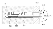
또한, 종래 다른 슬리브 확장앵커는 도 2에 도시된 바와 같이 확장 슬리브(302)가 볼트(310)와 동일한 중심 축을 가지며, 볼트 외곽 및 플라스틱 재료의 확장 슬리브 초기 고정장치(303)와 콘(301) 사이에 위치한다.2, the
즉, 천공홀(311)에 삽입된 후, 와셔(312)를 사이에 두고 정착판(313)과 밀착된 앵커 머리부분의 6각 볼트 혹은 너트를 토크 렌치로 돌려 토크를 가력하면, 볼트 외부의 나사산과 콘(301) 내부의 나사산이 상호 진행함에 따라 콘(301)이 확장슬리브((302)를 앵커 외부방향으로 밀어서 콘크리트에 확장시켜 콘크리트에 접합되어 지지력을 발휘하게 되는데, 이 부분에서 마찰력과 걸림턱이 동시에 작용하도록 되어 있다.That is, after the bolts are inserted into the
그런데, 종래 쐐기형 앵커 및 슬리브 확장앵커는 앵커 축 방향으로의 인장력이 작용할 때, 앵커를 구성하는 볼트의 강재파괴 보다는 콘크리트 파괴가 유발된다. 예를 들면, 앵커 웨지부분과 콘크리트 접합부위에서 응력이 집중되어 콘크리트 파괴가 진행된다.However, when a wedge-shaped anchor and a sleeve-extended anchor are subjected to a tensile force in the axial direction of the anchor, concrete failure occurs rather than the fracture of the bolts constituting the anchor. For example, the stress is concentrated on the anchor wedge portion and the concrete joint, resulting in concrete failure.
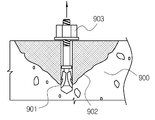
즉, 도 3에서 앵커에 앵커 축방향으로의 인장이 작용하면, 앵커의 웨지(903)와 콘크리트(900) 간의 접합부(901)에 응력이 집중되어 균열이 유발되고 집중되며, 피라미트 혹은 원추형의 파괴면(902)을 형성하며 파괴된다.3, stress is concentrated on the
종래 이러한 콘크리트 파괴는 앵커볼트의 강재 연성 파괴와는 달리 급작스럽게 일어나는 취성 파괴이므로 설계시에 보다 높은 감소계수 적용을 통해 성능을 저감하여 적용하고 있으며, 구조적으로는 연성파괴에 비해서 안정성 측면에서 불리한 거동이다. 이러한 경향은 쐐기 확장앵커 뿐만 아니라 슬리브 확장앵커에서도 동일하게 발생되었다.Conventionally, such concrete fracture is a brittle fracture that occurs suddenly unlike steel ductility fracture of an anchor bolt. Therefore, the performance is reduced by applying a higher reduction factor when designing, and it is structurally less favorable in terms of stability than ductile fracture to be. This tendency occurred not only in the wedge expansion anchor but also in the sleeve extension anchor.
이에 본 발명은 상기와 같은 종래 문제점을 해결하기 위해 발명된 것으로, 종래의 앵커에서 웨지와 콘크리트 간의 접합부에 응력이 집중되어 균열이 유발되어서 피라미드 혹은 원추형의 파괴면을 형성하여 파괴되는 경향을 해결한 테이퍼 나사산을 이용한 후설치 확장형 앵커를 제공함에 그 목적이 있다.Accordingly, the present invention has been made to solve the above-mentioned problems of the related art, and it is an object of the present invention to solve the above-mentioned problem that a stress is concentrated on a joint portion between a wedge and concrete in a conventional anchor to induce cracking to form a pyramid or a conical fracture surface The present invention provides an expansion anchor for a post installation using a taper thread.
즉, 본 발명은 앵커와 콘크리트 간의 접합 및 연결부위를 분산시킴을 통해, 앵커와 콘크리트 접합부위에서의 응력 집중현상을 완화하고, 이을 통해 외부 인장하중에 대해 콘크리트 초기균열 발현시점을 지연시켜 인장하중에 대한 저항성능을 향상시키는 앵커장치를 제공하는데 그 목적이 있다.In other words, the present invention mitigates the stress concentration phenomenon on the anchor and concrete joint by dispersing the joint between the anchor and the concrete, and delays the appearance of the initial crack in the concrete with respect to the external tensile load, And an object of the present invention is to provide an anchor device for improving the resistance performance of the anchor device.
또한 본 발명은 앵커시스템을 구성하는 세부구성을 단순화하여 시공성 및 경제성을 향상하고, 나아가 앵커 부착부위에서의 콘크리트 파괴 대신 앵커 자체의 강재파괴를 유도하여 안전성이 높은 앵커를 제공하고자 한다.The present invention also provides an anchor having a high degree of safety by simplifying the detailed construction of the anchor system to improve workability and economical efficiency, and further inducing fracture of the anchor itself in place of concrete failure at the anchor attachment site.
상기와 같은 목적을 달성하기 위한 본 발명은 확장 슬리브 대신에 방사방향으로의 확장이 가능하고, 외주면에 돌기 등이 형성되어 콘크리트와의 맞물림을 형성할 수 있도록 한 확장형 너트를 이용한 앵커를 제안하였으며, 이를 구현하기 위해 확장형 너트의 내주면과 볼트의 외주면은 테이퍼 나사산(볼트의 직경이 길이방향을 따라 변하는 나사산)을 적용한 구조로 되어 있다.In order to accomplish the above object, the present invention proposes an anchor using an expandable nut, which can expand in a radial direction instead of the expansion sleeve, and has protrusions or the like formed on its outer circumference to form engagement with concrete. In order to achieve this, the inner circumferential surface of the expandable nut and the outer circumferential surface of the bolt have a structure in which a taper thread (a thread whose diameter of the bolt varies along the longitudinal direction) is applied.
이러한 본 발명에 따른 테이퍼 나사산을 이용한 후설치 확장형 앵커는 종래기술대비 구성 및 시공이 간단하며, 지지대 이설 혹은 설치부위 콘크리트 손상 등에 따른 요구에 의해 앵커 제거가 필요한 경우, 천공홀을 추가 확장하거나 손상시키지 않고서는 앵커를 제거할 수 없는 한계가 있는 반면, 설치시의 토크와 반대방향의 토크를 작용하여, 볼트와 확장형 너트의 나사산 결합 해제를 통해 쉽게 제거 가능하도록 앵커시스템을 구성하여 교체가 용이해진다.The post-installation expandable anchor using the taper thread according to the present invention has a simple structure and construction as compared with the prior art, and when anchor removal is required due to the need for installation of a supporting stand or damage to concrete in an installation site, The anchor system can be configured to be easily removed by threaded disengagement of the bolt and the expandable nut by acting on the torque opposite to the torque at the time of installation so that the anchor system can be easily replaced.
또한, 방사방향으로의 확장을 가능하게 함을 통해 콘크리트 등으로 제작된 모재와의 접합부위를 늘려, 응력을 분산시켜 구조물의 파괴 대신 앵커자체의 파괴를 유도하여 안정성을 향상시킬 수 있는 효과가 있다.In addition, by expanding in the radial direction, it is possible to increase the joint portion with the base material made of concrete or the like and disperse the stress to induce fracture of the anchor itself instead of destruction of the structure, thereby improving the stability .
도 1은 종래 확장형 앵커의 설치상태 단면도,
도 2는 종래 다른 확장형 앵커의 설치상태 단면도,
도 3은 종래 확장형 앵커의 콘크리트 파괴상태를 보여주는 단면도,
도 4는 본 발명에 따른 확장형 앵커의 분리 사시도,
도 5는 본 발명의 콘크리트에 장착된 상태를 보여주는 단면도,
도 6 (A)와 (B)는 볼트와 확장가능한 너트의 확장 전과 확장 후를 보여주는 부분확대 단면도들,
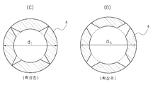
도 7 (C)와 (D)는 확장 가능한 너트의 확장 전과 확장 후를 보여주는 평면도들이다.1 is a cross-sectional view of a conventional expandable anchor,
FIG. 2 is a sectional view of another conventional expansion anchor,
3 is a cross-sectional view showing a concrete failure state of a conventional expandable anchor,
4 is an exploded perspective view of an expandable anchor according to the present invention,
FIG. 5 is a sectional view showing a state in which the concrete according to the present invention is mounted,
FIGS. 6 (A) and 6 (B) are partially enlarged cross-sectional views showing the expansion of the bolt and the expandable nut before and after expansion,
Figs. 7C and 7D are plan views showing the extension of the expandable nut before and after expansion. Fig.
이하, 본 발명의 바람직한 실시예를 첨부도면에 의거 상세히 설명한다.Hereinafter, preferred embodiments of the present invention will be described in detail with reference to the accompanying drawings.
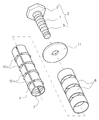
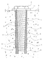
도 4는 본 발명에 따른 테이퍼 나사산을 이용한 후설치 확장형 앵커의 분리 사시도이고, 도 5는 도 4의 앵커가 콘크리트에 장착된 상태를 보여주는 장착 단면도이다.FIG. 4 is an exploded perspective view of a post-installation expanding anchor using a taper thread according to the present invention, and FIG. 5 is a mounting cross-sectional view showing an anchor of FIG. 4 mounted on concrete.
본 발명은 콘크리트 건축 구조물에 부착물을 고정시키기 위해 볼트 본체(1)와 볼트 머리(2)를 갖춘 앵커볼트(3)와 너트(4)를 구비하여 이루어진 앵커에 있어서, 상기 앵커볼트(3)의 볼트 본체(1) 외주면에는 수나사(5)가 형성되고, 상기 너트(4)는 직경방향으로 확장 가능하도록 원통부로 형성되며, 상기 너트(4)의 초기 불필요한 변형을 잡아주기 위해 신축부재(6)가 너트(4) 바깥 둘레면에 장착된 구조로 되어 있다.The present invention relates to an anchor having an anchor bolt (3) having a bolt body (1) and a bolt head (2) and a nut (4) for fixing an attachment to a concrete building structure, A
여기서 상기 볼트 본체(1)는 볼트 머리(2)의 반대방향으로 점차 외경이 축소되는 형태의 원뿔형태로 이루어질 수 있다.Here, the
확장형 너트(4)는 확장 가능하도록 분리되는 원통형태로 이루어지되, 확장형 너트(4)는 내면에 볼트 머리(2)의 반대방향으로 점차 내경이 축소되는 형태의 내면 나사산(7)이 형성될 수 있다. 또한 초기에 확장형 너트의 불필요한 변형을 잡아주기 위한 신축부재(6)는 외부 띠 형태로 고무소재, 우레탄 소재, 신축력이 좋은 천소재 등 다양하게 적용될 수 있다.The
상기 앵커볼트(3)가 확장형 너트(4)에 체결되어감에 따라 확장형 너트(4)의 외면이 점차 방사방향으로 확장되어 감에 따라 이를 둘러싼 콘크리트 홀(8)에 접합된다.As the
여기서 상기 볼트 본체(1)의 길이는 확장형 너트(4)의 전체길이와 거의 유사하거나, 더 길게 마련되는 것이 바람직하다.Here, the length of the
또한 상기 확장형 너트(4)는 콘크리트(9)와 같은 기초에 균열이 발생되는 것을 방지하기 위하여 균일한 압력으로 가압하는 것이 바람직하며, 인장하중 작용시에 응력을 분담해줌이 바람직하다.In addition, it is preferable that the
따라서 상기 확장형 너트(4)는 선단부로부터 말단부에 이르기까지 동일한 외경을 가지며, 길이방향으로 형성되는 복수 개의 절단선에 의해 앵커볼트(3)를 중심으로 하는 방사형으로 분리될 수 있으며, 적절하게 분포된 외부돌기(10) 등을 통해 콘크리트(9)와의 접합을 더욱 용이하게 할 수 있다.The
도면 중 미설명부호 11은 정착판이다.In the figure,
도 6 (A)와 (B)는 상기 볼트 본체(1)에 확장형 너트(4)가 나선 체결되어 확장전 직경(di)와 확장후 직경(dh)의 상태를 보여주고, 도 7 (C)와 (D)는 상기 너트(4)의 확장적 직경(di)와 확장후 직경(dh)를 보여주고 있다.6 (A) and 6 (B) show the state of the expanded front diameter d i and the expanded posterior diameter d h by fastening the
1 : 볼트 본체,
2 : 볼트 머리,
3 : 앵커볼트,
4 : 너트,
5 : 수나사,
6 : 신축부재,
7 : 나사산,
8 : 홀,
9 : 콘크리트,
10 : 외부돌기.1: bolt body, 2: bolt head,
3: anchor bolt, 4: nut,
5: male thread, 6: elastic member,
7: thread, 8: hole,
9: Concrete, 10: Outer projection.
Claims (4)
상기 앵커볼트(3)의 볼트 본체(1) 외주면에는 수나사(5)가 형성되고, 상기 너트(4)는 직경방향으로 확장 가능하도록 원통부로 형성되며, 상기 너트(4)의 초기 불필요한 변형을 잡아주기 위해 신축부재(6)가 너트(4) 바깥 둘레면에 장착된 것을 특징으로 하는 테이퍼 나사산을 이용한 후설치 확장형 앵커.An anchor comprising an anchor bolt (3) having a bolt body (1) and a bolt head (2) and a nut (4) for fixing an attachment to a concrete building structure,
A male thread 5 is formed on the outer circumferential surface of the bolt body 1 of the anchor bolt 3 and the nut 4 is formed as a cylindrical portion so as to extend in the radial direction, Wherein the elastic member (6) is mounted on the outer circumferential surface of the nut (4).
상기 볼트 본체(1)는 볼트 머리(2)의 반대방향으로 점차 외경이 축소되는 형태의 원뿔형태로 이루어진 것을 특징으로 하는 테이퍼 나사산을 이용한 후설치 확장형 앵커.The method according to claim 1,
Wherein the bolt body (1) has a conical shape in which the outer diameter gradually decreases in a direction opposite to the bolt head (2).
상기 신축부재(6)는 외부 띠 형태로 고무소재, 우레탄 소재, 신축력이 좋은 천소재로 된 것을 특징으로 하는 테이퍼 나사산을 이용한 후설치 확장형 앵커.The method according to claim 1,
Characterized in that the elastic member (6) is made of a rubber material, a urethane material and a stretchable cloth material in the form of an outer band.
상기 볼트 본체(1)의 길이는 확장형 너트(4)의 전체길이와 거의 유사하거나, 더 길게된 것을 특징으로 하는 테이퍼 나사산을 이용한 후설치 확장형 앵커.The method according to claim 1,
Wherein the length of the bolt body (1) is substantially equal to or longer than the total length of the expandable nut (4).
Priority Applications (1)
| Application Number | Priority Date | Filing Date | Title |
|---|---|---|---|
| KR1020140149871A KR20160052019A (en) | 2014-10-31 | 2014-10-31 | Post-installed epansion anchor with tapered thread |
Applications Claiming Priority (1)
| Application Number | Priority Date | Filing Date | Title |
|---|---|---|---|
| KR1020140149871A KR20160052019A (en) | 2014-10-31 | 2014-10-31 | Post-installed epansion anchor with tapered thread |
Publications (1)
| Publication Number | Publication Date |
|---|---|
| KR20160052019A true KR20160052019A (en) | 2016-05-12 |
Family
ID=56024588
Family Applications (1)
| Application Number | Title | Priority Date | Filing Date |
|---|---|---|---|
| KR1020140149871A Ceased KR20160052019A (en) | 2014-10-31 | 2014-10-31 | Post-installed epansion anchor with tapered thread |
Country Status (1)
| Country | Link |
|---|---|
| KR (1) | KR20160052019A (en) |
Cited By (1)
| Publication number | Priority date | Publication date | Assignee | Title |
|---|---|---|---|---|
| KR102722004B1 (en) * | 2023-05-31 | 2024-10-28 | 주식회사 세진기술개발 | the improved expandable type anchor structure |
-
2014
- 2014-10-31 KR KR1020140149871A patent/KR20160052019A/en not_active Ceased
Cited By (1)
| Publication number | Priority date | Publication date | Assignee | Title |
|---|---|---|---|---|
| KR102722004B1 (en) * | 2023-05-31 | 2024-10-28 | 주식회사 세진기술개발 | the improved expandable type anchor structure |
Similar Documents
| Publication | Publication Date | Title |
|---|---|---|
| JP5778791B2 (en) | Anchoring element | |
| US8974151B2 (en) | Constant-resistance large-deformation anchor rod | |
| US9133871B2 (en) | Expansion plug | |
| CN102076977B (en) | Radially expanding bolt assembly | |
| US4339217A (en) | Expanding anchor bolt assembly | |
| KR20130084223A (en) | Expanding anchor | |
| CN110662883A (en) | Friction Rock Bolt | |
| CN103541982B (en) | A kind of Nested-type single-side bolt fastener | |
| CN104956031A (en) | Rock bolt | |
| KR20200093381A (en) | Set anchor bolt | |
| JP5342118B2 (en) | Method of drilling bottomed hole in surface layer of concrete and anchor fitting used for drilling bottomed hole | |
| CN210239718U (en) | A pressure-yielding fastening device for protecting the threaded section of the anchor bolt tail | |
| KR20160052019A (en) | Post-installed epansion anchor with tapered thread | |
| JP7449370B2 (en) | expansion anchor | |
| TWI688713B (en) | Metal expansion anchor | |
| CN108625534B (en) | Knurling formula is planted muscle anchor head device | |
| JP2014237988A (en) | Post-construction anchor and post-construction anchor system | |
| JP7511866B2 (en) | Metal Expansion Anchor | |
| CN216841750U (en) | Prestressed expansion shell anchor rod | |
| JP2018080499A (en) | Connection method of steel pipe pile | |
| EP3207264A1 (en) | Anchor assembly | |
| CN223104982U (en) | A screw-type expansion anchor bolt that prevents penetration and damage | |
| JP2007239804A (en) | Anchor bolt | |
| CN219139570U (en) | High-strength anti-pulling screw assembly | |
| JP2002349522A (en) | Mechanical anchor bolt |
Legal Events
| Date | Code | Title | Description |
|---|---|---|---|
| A201 | Request for examination | ||
| PA0109 | Patent application |
Patent event code: PA01091R01D Comment text: Patent Application Patent event date: 20141031 |
|
| PA0201 | Request for examination | ||
| E902 | Notification of reason for refusal | ||
| PE0902 | Notice of grounds for rejection |
Comment text: Notification of reason for refusal Patent event date: 20151020 Patent event code: PE09021S01D |
|
| E601 | Decision to refuse application | ||
| PE0601 | Decision on rejection of patent |
Patent event date: 20160421 Comment text: Decision to Refuse Application Patent event code: PE06012S01D Patent event date: 20151020 Comment text: Notification of reason for refusal Patent event code: PE06011S01I |
|
| PG1501 | Laying open of application |