KR20160056414A - 마찰 교반 접합 장치 - Google Patents
마찰 교반 접합 장치 Download PDFInfo
- Publication number
- KR20160056414A KR20160056414A KR1020140155805A KR20140155805A KR20160056414A KR 20160056414 A KR20160056414 A KR 20160056414A KR 1020140155805 A KR1020140155805 A KR 1020140155805A KR 20140155805 A KR20140155805 A KR 20140155805A KR 20160056414 A KR20160056414 A KR 20160056414A
- Authority
- KR
- South Korea
- Prior art keywords
- welding
- tool
- friction stir
- guide
- guide track
- Prior art date
- Legal status (The legal status is an assumption and is not a legal conclusion. Google has not performed a legal analysis and makes no representation as to the accuracy of the status listed.)
- Granted
Links
Images






Classifications
-
- B—PERFORMING OPERATIONS; TRANSPORTING
- B23—MACHINE TOOLS; METAL-WORKING NOT OTHERWISE PROVIDED FOR
- B23K—SOLDERING OR UNSOLDERING; WELDING; CLADDING OR PLATING BY SOLDERING OR WELDING; CUTTING BY APPLYING HEAT LOCALLY, e.g. FLAME CUTTING; WORKING BY LASER BEAM
- B23K20/00—Non-electric welding by applying impact or other pressure, with or without the application of heat, e.g. cladding or plating
- B23K20/12—Non-electric welding by applying impact or other pressure, with or without the application of heat, e.g. cladding or plating the heat being generated by friction; Friction welding
- B23K20/122—Non-electric welding by applying impact or other pressure, with or without the application of heat, e.g. cladding or plating the heat being generated by friction; Friction welding using a non-consumable tool, e.g. friction stir welding
- B23K20/1265—Non-butt welded joints, e.g. overlap-joints, T-joints or spot welds
-
- B—PERFORMING OPERATIONS; TRANSPORTING
- B23—MACHINE TOOLS; METAL-WORKING NOT OTHERWISE PROVIDED FOR
- B23K—SOLDERING OR UNSOLDERING; WELDING; CLADDING OR PLATING BY SOLDERING OR WELDING; CUTTING BY APPLYING HEAT LOCALLY, e.g. FLAME CUTTING; WORKING BY LASER BEAM
- B23K20/00—Non-electric welding by applying impact or other pressure, with or without the application of heat, e.g. cladding or plating
- B23K20/12—Non-electric welding by applying impact or other pressure, with or without the application of heat, e.g. cladding or plating the heat being generated by friction; Friction welding
- B23K20/122—Non-electric welding by applying impact or other pressure, with or without the application of heat, e.g. cladding or plating the heat being generated by friction; Friction welding using a non-consumable tool, e.g. friction stir welding
- B23K20/1245—Non-electric welding by applying impact or other pressure, with or without the application of heat, e.g. cladding or plating the heat being generated by friction; Friction welding using a non-consumable tool, e.g. friction stir welding characterised by the apparatus
- B23K20/125—Rotary tool drive mechanism
-
- B—PERFORMING OPERATIONS; TRANSPORTING
- B23—MACHINE TOOLS; METAL-WORKING NOT OTHERWISE PROVIDED FOR
- B23K—SOLDERING OR UNSOLDERING; WELDING; CLADDING OR PLATING BY SOLDERING OR WELDING; CUTTING BY APPLYING HEAT LOCALLY, e.g. FLAME CUTTING; WORKING BY LASER BEAM
- B23K20/00—Non-electric welding by applying impact or other pressure, with or without the application of heat, e.g. cladding or plating
- B23K20/12—Non-electric welding by applying impact or other pressure, with or without the application of heat, e.g. cladding or plating the heat being generated by friction; Friction welding
- B23K20/122—Non-electric welding by applying impact or other pressure, with or without the application of heat, e.g. cladding or plating the heat being generated by friction; Friction welding using a non-consumable tool, e.g. friction stir welding
- B23K20/1245—Non-electric welding by applying impact or other pressure, with or without the application of heat, e.g. cladding or plating the heat being generated by friction; Friction welding using a non-consumable tool, e.g. friction stir welding characterised by the apparatus
- B23K20/126—Workpiece support, i.e. backing or clamping
-
- B—PERFORMING OPERATIONS; TRANSPORTING
- B23—MACHINE TOOLS; METAL-WORKING NOT OTHERWISE PROVIDED FOR
- B23K—SOLDERING OR UNSOLDERING; WELDING; CLADDING OR PLATING BY SOLDERING OR WELDING; CUTTING BY APPLYING HEAT LOCALLY, e.g. FLAME CUTTING; WORKING BY LASER BEAM
- B23K37/00—Auxiliary devices or processes, not specially adapted for a procedure covered by only one of the other main groups of this subclass
- B23K37/02—Carriages for supporting the welding or cutting element
- B23K37/0282—Carriages forming part of a welding unit
-
- B—PERFORMING OPERATIONS; TRANSPORTING
- B23—MACHINE TOOLS; METAL-WORKING NOT OTHERWISE PROVIDED FOR
- B23K—SOLDERING OR UNSOLDERING; WELDING; CLADDING OR PLATING BY SOLDERING OR WELDING; CUTTING BY APPLYING HEAT LOCALLY, e.g. FLAME CUTTING; WORKING BY LASER BEAM
- B23K2101/00—Articles made by soldering, welding or cutting
- B23K2101/04—Tubular or hollow articles
- B23K2101/06—Tubes
Landscapes
- Engineering & Computer Science (AREA)
- Mechanical Engineering (AREA)
- Physics & Mathematics (AREA)
- Optics & Photonics (AREA)
- Pressure Welding/Diffusion-Bonding (AREA)
Abstract
Description
도 2는 종래 기술에 의한 배관 이음매 용접 방법 설명을 위한 결합 개념도.
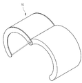
도 3은 본 발명에 의한 마찰 교반 접합 장치의 가이드 궤도 구성 개요도.
도 4는 도 3의 요부 단면 개요도.
도 5는 본 발명에 의한 마찰 교반 접합 장치의 용접장치부 구성 개념도.
도 6은 본 발명에 의한 가이드부의 개요도.
도 7은 본 발명에 의한 전동 주행장치의 개요도.
도 8은 본 발명에 의한 아이들 주행장치의 개요도.
도 9는 본 발명에 의한 용접툴부의 개요도.
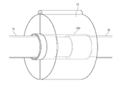
도 10은 본 발명의 마찰 교반 접합 장치를 배관 이음매에 설치한 개요도.
도 11의 (가) 및 (나)는 커플링의 구성과 커플링 설치 예시도.
도 12는 본 발명에 의한 마찰 교반 접합 장치를 배관 이음매에 설치한 단면 예시도.
도 13 및 도 14는 본 발명에 의한 배관 겹치기 이음매 마찰 교반 접합 방법 설명도.
11 : 요홈부 12 : 이탈방지홈
13 : 궤도부 20, 20a : 이동가이드
21 : 롤러 22 : 브라켓
30 : 전동 주행장치 31 : 주행장치 하우징
32 : 모터 33 : 기어부
30a : 아이들 주행장치 33a : 아이들 기어부
40 : 용접툴부 41 : 하우징
42 : 상하 이동수단 43 : 좌우 이동수단
43a : 이송스크류 44 : 툴박스
50 : 용접툴
Claims (16)
- 배관의 겹치기 이음매 접합을 위한 마찰 교반 접합 장치에 있어서,
배관의 겹치기 이음매 부분의 둘레를 감싸며, 내면에 요홈부(11)가 형성된 가이드 궤도(10)와;
상기 가이드 궤도(10)의 요홈부(11)에 장착되어 요홈부(11) 내주면을 타고 이동하면서 용접툴에 의해 마찰 교반 접합 용접을 수행하는 용접장치부를 포함하여 이루어진 것을 특징으로 하는 마찰 교반 접합 장치.
- 제 1 항에 있어서,
상기 배관의 겹치기 이음매 부분은, 일측 및 타측 배관(1a)(1b)을 양측에서 삽입 결합하는 커플링(100)을 포함하여 이루어지고, 가이드 궤도(10)는 상기 커플링(100)의 둘레를 감싸는 것을 특징으로 하는 마찰 교반 접합 장치.
- 제 2 항에 있어서, 상기 커플링(100)은,
양단부에 배관(1a)(1b)의 외경과 같은 내경이 형성되고, 중간부에 상기 용접툴의 프로브 길이보다 큰 두께를 갖는 협지부(101)가 형성된 것을 특징으로 하는 마찰 교반 접합 장치.
- 제 1 항에 있어서, 상기 가이드 궤도(10)는,
둘로 분리된 가이드 궤도(10)를 배관 겹치기 이음매 부분을 감싸도록 설치하여 고정시킬 수 있는 클램프 타입인 것을 특징으로 하는 마찰 교반 접합 장치.
- 제 1 항에 있어서, 상기 가이드 궤도(10)는,
요홈부(11) 내측면에 주행가이드 수단과, 용접장치부의 이탈방지 수단이 형성된 것을 특징으로 하는 마찰 교반 접합 장치.
- 제 1 항에 있어서, 상기 용접장치부는,
배관 겹치기 이음매 부분의 상면에 마찰 교반 접합 용접을 수행하는 용접툴이 설치된 용접툴부(40)와;
상기 용접툴부(40)를 상기 가이드 궤도(10)의 내주면을 타고 이송시키기 위한 주행수단(30)을 포함하는 것을 특징으로 하는 마찰 교반 접합 장치.
- 제 6 항에 있어서, 상기 용접장치부는,
상기 용접툴(50)을 상기 가이드 궤도(10) 내부에서 상하 좌우 이동시키는 툴 이동수단을 더 포함하는 것을 특징으로 하는 마찰 교반 접합 장치.
- 제 6 항에 있어서, 상기 주행수단은,
가이드 궤도(10)의 요홈부(11) 내에 이송가능하게 설치되는 주행장치 하우징(31)과, 상기 주행장치 하우징(31) 속에 고정설치되는 주행 모터(32)와, 주행모터(32)에 의해 회전되어 상기 가이드 궤도(10)의 내측벽에 형성된 궤도부(13)에 맞물려 용접장치부를 주행시키는 기어부(33)로 구성된 것을 특징으로 하는 마찰 교반 접합 장치.
- 제 6 항에 있어서, 상기 주행수단은,
상기 용접툴부(40)의 전단에, 동력에 의해 구동되는 전동 주행장치(30)이 설치되고, 용접툴부(40)의 후단에는 동력 없이 아이들 기어(33a)에 의해 주행가이드를 하는 아이들 주행장치(30a)이 설치되는 것을 특징으로 하는 마찰 교반 접합 장치.
- 제 6 항에 있어서, 상기 용접장치부는,
상기 주행수단의 전단부에 설치되어 상기 가이드 궤도(10)의 요홈부(11) 내주면을 타고 용접장치부가 이송되도록 가이드하는 이송가이드 수단을 더 포함하는 것을 특징으로 하는 마찰 교반 접합 장치.
- 제 10 항에 있어서, 상기 이송가이드 수단은,
브라켓(22)의 외측부에 상기 가이드 레일(10)의 이탈방지홈(12) 속에 삽입되는 이탈방지돌기(23)가 양측으로 돌출되고, 브라켓(22)의 상단에 회전가능하게 롤러(21)가 설치되어 가이드 궤도(10)의 요홈부(11) 상면에 회전 접촉되게 구성된 것을 특징으로 하는 마찰 교반 접합 장치.
- 제 10 항에 있어서, 상기 이송 가이드 수단은,
용접장치부의 앞뒤에 각각 설치되어 피동 회전되는 롤러에 의해 가이드 궤도의 상면과 회전접촉되어 용접 장치부의 전진 및 후진 이송을 가이드 하는 두 개의 이송가이드(20)(20a)로 구성된 것을 특징으로 하는 마찰 교반 접합 장치.
- 제 7 항에 있어서, 상기 용접툴부(40)의 툴 이동수단은,
상기 가이드 궤도(10)의 요홈부(11) 속에 이송 가능하게 장착되고, 하면이 개방된 하우징(41)과;
상기 하우징(41)의 내측 상면에 설치되어 상하이동력을 발생하는 상하이동수단(42)과,
상기 상하이동수단(42)의 작동로드에 고정설치되어 상기 하우징(41) 내측에서 상하 이동가능하게 설치되는 툴박스(44)와,
상기 툴박스(44) 내부에 설치되는 상기 용접툴(50)을 툴박스(44) 내부에서 좌우 이동시키는 좌우이동수단을 포함하는 것을 특징으로 하는 마찰 교반 접합 장치.
- 제 13 항에 있어서, 상기 좌우이동수단은,
툴박스(44)의 내부 좌우측에 설치되는 유압실린더와, 좌우측 유압실린더를 연통시키는 유압배관에 설치되어 좌우 유압을 조절하여 상기 용접툴(50)의 좌우 이동을 제어하는 유압제어수단을 포함하는 것을 특징으로 하는 마찰 교반 접합 장치.
- 제 13 항에 있어서, 상기 좌우이동수단은,
상기 툴박스(44)의 내측 좌우를 가로질러 설치되고, 중간에 나사결합으로 상기 용접툴(50)이 결합된 이송스크류(43a)와, 상기 이송스크류(43a)를 정역방향 회전시키기 위한 모터(43)를 포함하여 이루어진 것을 특징으로 하는 마찰 교반 접합 장치. - 제 6 항에 있어서, 상기 용접장치부는,
적어도 하나 이상 복수의 용접툴부가 배열 설치된 것을 특징으로 하는 마찰 교반 접합 장치.
Priority Applications (1)
| Application Number | Priority Date | Filing Date | Title |
|---|---|---|---|
| KR1020140155805A KR101631557B1 (ko) | 2014-11-11 | 2014-11-11 | 마찰 교반 접합 장치 |
Applications Claiming Priority (1)
| Application Number | Priority Date | Filing Date | Title |
|---|---|---|---|
| KR1020140155805A KR101631557B1 (ko) | 2014-11-11 | 2014-11-11 | 마찰 교반 접합 장치 |
Publications (2)
| Publication Number | Publication Date |
|---|---|
| KR20160056414A true KR20160056414A (ko) | 2016-05-20 |
| KR101631557B1 KR101631557B1 (ko) | 2016-06-27 |
Family
ID=56103599
Family Applications (1)
| Application Number | Title | Priority Date | Filing Date |
|---|---|---|---|
| KR1020140155805A Expired - Fee Related KR101631557B1 (ko) | 2014-11-11 | 2014-11-11 | 마찰 교반 접합 장치 |
Country Status (1)
| Country | Link |
|---|---|
| KR (1) | KR101631557B1 (ko) |
Cited By (3)
| Publication number | Priority date | Publication date | Assignee | Title |
|---|---|---|---|---|
| KR20180000572A (ko) | 2016-06-23 | 2018-01-03 | 대우조선해양 주식회사 | 마찰교반접합 장치 |
| EP3881964A1 (en) * | 2020-03-17 | 2021-09-22 | Siemens Gamesa Renewable Energy A/S | Method of connecting by welding two sections of a structure, especially of a wind turbine, and corresponding connection tool |
| KR20230171150A (ko) * | 2022-06-13 | 2023-12-20 | 한국토지주택공사 | 상수도관 연결 조인트 및 이를 활용한 누수 측정 시스템 |
Citations (5)
| Publication number | Priority date | Publication date | Assignee | Title |
|---|---|---|---|---|
| KR20000061468A (ko) * | 1999-03-26 | 2000-10-16 | 김영환 | 전압 승압 회로 |
| JP2006061983A (ja) * | 2004-07-29 | 2006-03-09 | Showa Denko Kk | 中空状被接合材の摩擦攪拌接合方法 |
| JP2006518671A (ja) * | 2003-01-30 | 2006-08-17 | スミス インターナショナル、インコーポレテッド | 高融点材料のアウト−オブ−ポジション摩擦攪拌溶接 |
| KR100829993B1 (ko) * | 2006-12-14 | 2008-05-16 | 웰텍 주식회사 | 강관의 외면접합부 용접장치 |
| US20110075774A1 (en) | 2009-09-30 | 2011-03-31 | Motorola, Inc. | Method and apparatus for mitigation of interference |
-
2014
- 2014-11-11 KR KR1020140155805A patent/KR101631557B1/ko not_active Expired - Fee Related
Patent Citations (5)
| Publication number | Priority date | Publication date | Assignee | Title |
|---|---|---|---|---|
| KR20000061468A (ko) * | 1999-03-26 | 2000-10-16 | 김영환 | 전압 승압 회로 |
| JP2006518671A (ja) * | 2003-01-30 | 2006-08-17 | スミス インターナショナル、インコーポレテッド | 高融点材料のアウト−オブ−ポジション摩擦攪拌溶接 |
| JP2006061983A (ja) * | 2004-07-29 | 2006-03-09 | Showa Denko Kk | 中空状被接合材の摩擦攪拌接合方法 |
| KR100829993B1 (ko) * | 2006-12-14 | 2008-05-16 | 웰텍 주식회사 | 강관의 외면접합부 용접장치 |
| US20110075774A1 (en) | 2009-09-30 | 2011-03-31 | Motorola, Inc. | Method and apparatus for mitigation of interference |
Cited By (5)
| Publication number | Priority date | Publication date | Assignee | Title |
|---|---|---|---|---|
| KR20180000572A (ko) | 2016-06-23 | 2018-01-03 | 대우조선해양 주식회사 | 마찰교반접합 장치 |
| EP3881964A1 (en) * | 2020-03-17 | 2021-09-22 | Siemens Gamesa Renewable Energy A/S | Method of connecting by welding two sections of a structure, especially of a wind turbine, and corresponding connection tool |
| WO2021185488A1 (en) * | 2020-03-17 | 2021-09-23 | Siemens Gamesa Renewable Energy A/S | Method of connecting by welding two sections of a structure, especially of a wind turbine, and corresponding connection tool |
| CN115210037A (zh) * | 2020-03-17 | 2022-10-18 | 西门子歌美飒可再生能源公司 | 通过焊接结构、尤其是风力涡轮机的两个区段进行连接的方法以及对应的连接工具 |
| KR20230171150A (ko) * | 2022-06-13 | 2023-12-20 | 한국토지주택공사 | 상수도관 연결 조인트 및 이를 활용한 누수 측정 시스템 |
Also Published As
| Publication number | Publication date |
|---|---|
| KR101631557B1 (ko) | 2016-06-27 |
Similar Documents
| Publication | Publication Date | Title |
|---|---|---|
| KR101520398B1 (ko) | 파이프 단면부의 자동 알곤 용접장치 | |
| KR101344343B1 (ko) | 대형관 타입의 파이프 자동 용접 시스템 | |
| US8109428B2 (en) | Method of and apparatus for splicing metal strips | |
| US10835981B2 (en) | Method for circumferential welding and a robotic welding system for circumferential welding | |
| US10040141B2 (en) | Laser controlled internal welding machine for a pipeline | |
| US7078647B2 (en) | Arc-enhanced friction stir welding | |
| US7793816B2 (en) | Friction stir welding apparatus | |
| KR102085264B1 (ko) | 강관의 용접이음을 위한 보조장치 및 이를 이용한 강관의 현장시공 연결방법 | |
| US20090134203A1 (en) | Methods and apparatus for forming tubular strings | |
| EP3142822B1 (en) | Fabrication of pipe strings using friction stir welding | |
| CN102500913A (zh) | 钢质管道摩擦焊接设备 | |
| KR101569365B1 (ko) | 파이프 단면부의 자동 알곤 용접장치 | |
| KR101631557B1 (ko) | 마찰 교반 접합 장치 | |
| JP6302782B2 (ja) | 欠陥補修装置及び欠陥補修方法 | |
| KR20120004519U (ko) | 자동 tig 용접 장치 | |
| JP3079486B2 (ja) | 角鋼管の溶接装置及び溶接方法 | |
| KR20130005530A (ko) | 터닝롤러를 이용한 강관형 일렉트로가스 용접장치 | |
| CN108723647B (zh) | 一种高强度金属管焊接装置 | |
| CN119261214A (zh) | 给水用聚氯乙烯电热熔管件的熔接方法 | |
| KR20160056413A (ko) | 배관 겹치기 이음매 접합을 위한 마찰교반 접합 방법 | |
| WO2018188335A1 (zh) | 一种角焊小车 | |
| CN110722279A (zh) | 一种钢管对接焊接工艺 | |
| KR101186114B1 (ko) | 핸드 필렛 용접용 캐리지 | |
| KR20180077488A (ko) | 서브머지드 아크 용접 장치 | |
| JP7849232B2 (ja) | 突き合せ装置および突き合せ方法 |
Legal Events
| Date | Code | Title | Description |
|---|---|---|---|
| A201 | Request for examination | ||
| PA0109 | Patent application |
St.27 status event code: A-0-1-A10-A12-nap-PA0109 |
|
| PA0201 | Request for examination |
St.27 status event code: A-1-2-D10-D11-exm-PA0201 |
|
| D13-X000 | Search requested |
St.27 status event code: A-1-2-D10-D13-srh-X000 |
|
| D14-X000 | Search report completed |
St.27 status event code: A-1-2-D10-D14-srh-X000 |
|
| E902 | Notification of reason for refusal | ||
| PE0902 | Notice of grounds for rejection |
St.27 status event code: A-1-2-D10-D21-exm-PE0902 |
|
| E13-X000 | Pre-grant limitation requested |
St.27 status event code: A-2-3-E10-E13-lim-X000 |
|
| P11-X000 | Amendment of application requested |
St.27 status event code: A-2-2-P10-P11-nap-X000 |
|
| P13-X000 | Application amended |
St.27 status event code: A-2-2-P10-P13-nap-X000 |
|
| E701 | Decision to grant or registration of patent right | ||
| PE0701 | Decision of registration |
St.27 status event code: A-1-2-D10-D22-exm-PE0701 |
|
| PG1501 | Laying open of application |
St.27 status event code: A-1-1-Q10-Q12-nap-PG1501 |
|
| GRNT | Written decision to grant | ||
| PR0701 | Registration of establishment |
St.27 status event code: A-2-4-F10-F11-exm-PR0701 |
|
| PR1002 | Payment of registration fee |
St.27 status event code: A-2-2-U10-U11-oth-PR1002 Fee payment year number: 1 |
|
| PG1601 | Publication of registration |
St.27 status event code: A-4-4-Q10-Q13-nap-PG1601 |
|
| R18-X000 | Changes to party contact information recorded |
St.27 status event code: A-5-5-R10-R18-oth-X000 |
|
| P22-X000 | Classification modified |
St.27 status event code: A-4-4-P10-P22-nap-X000 |
|
| P22-X000 | Classification modified |
St.27 status event code: A-4-4-P10-P22-nap-X000 |
|
| FPAY | Annual fee payment |
Payment date: 20190612 Year of fee payment: 4 |
|
| PR1001 | Payment of annual fee |
St.27 status event code: A-4-4-U10-U11-oth-PR1001 Fee payment year number: 4 |
|
| PC1903 | Unpaid annual fee |
St.27 status event code: A-4-4-U10-U13-oth-PC1903 Not in force date: 20200614 Payment event data comment text: Termination Category : DEFAULT_OF_REGISTRATION_FEE |
|
| PC1903 | Unpaid annual fee |
St.27 status event code: N-4-6-H10-H13-oth-PC1903 Ip right cessation event data comment text: Termination Category : DEFAULT_OF_REGISTRATION_FEE Not in force date: 20200614 |
|
| R18-X000 | Changes to party contact information recorded |
St.27 status event code: A-5-5-R10-R18-oth-X000 |
|
| PN2301 | Change of applicant |
St.27 status event code: A-5-5-R10-R13-asn-PN2301 St.27 status event code: A-5-5-R10-R11-asn-PN2301 |
|
| P22-X000 | Classification modified |
St.27 status event code: A-4-4-P10-P22-nap-X000 |