KR20160077108A - Buffing expanded foam items - Google Patents
Buffing expanded foam items Download PDFInfo
- Publication number
- KR20160077108A KR20160077108A KR1020167013289A KR20167013289A KR20160077108A KR 20160077108 A KR20160077108 A KR 20160077108A KR 1020167013289 A KR1020167013289 A KR 1020167013289A KR 20167013289 A KR20167013289 A KR 20167013289A KR 20160077108 A KR20160077108 A KR 20160077108A
- Authority
- KR
- South Korea
- Prior art keywords
- article
- chamber
- buffing
- particles
- foamed
- Prior art date
- Legal status (The legal status is an assumption and is not a legal conclusion. Google has not performed a legal analysis and makes no representation as to the accuracy of the status listed.)
- Granted
Links
Images











Classifications
-
- B—PERFORMING OPERATIONS; TRANSPORTING
- B29—WORKING OF PLASTICS; WORKING OF SUBSTANCES IN A PLASTIC STATE IN GENERAL
- B29C—SHAPING OR JOINING OF PLASTICS; SHAPING OF MATERIAL IN A PLASTIC STATE, NOT OTHERWISE PROVIDED FOR; AFTER-TREATMENT OF THE SHAPED PRODUCTS, e.g. REPAIRING
- B29C44/00—Shaping by internal pressure generated in the material, e.g. swelling or foaming ; Producing porous or cellular expanded plastics articles
- B29C44/02—Shaping by internal pressure generated in the material, e.g. swelling or foaming ; Producing porous or cellular expanded plastics articles for articles of definite length, i.e. discrete articles
- B29C44/08—Shaping by internal pressure generated in the material, e.g. swelling or foaming ; Producing porous or cellular expanded plastics articles for articles of definite length, i.e. discrete articles using several expanding or moulding steps
-
- A—HUMAN NECESSITIES
- A43—FOOTWEAR
- A43B—CHARACTERISTIC FEATURES OF FOOTWEAR; PARTS OF FOOTWEAR
- A43B13/00—Soles; Sole-and-heel integral units
- A43B13/02—Soles; Sole-and-heel integral units characterised by the material
- A43B13/04—Plastics, rubber or vulcanised fibre
-
- A—HUMAN NECESSITIES
- A43—FOOTWEAR
- A43B—CHARACTERISTIC FEATURES OF FOOTWEAR; PARTS OF FOOTWEAR
- A43B7/00—Footwear with health or hygienic arrangements
- A43B7/14—Footwear with health or hygienic arrangements with foot-supporting parts
- A43B7/1405—Footwear with health or hygienic arrangements with foot-supporting parts with pads or holes on one or more locations, or having an anatomical or curved form
- A43B7/1475—Footwear with health or hygienic arrangements with foot-supporting parts with pads or holes on one or more locations, or having an anatomical or curved form characterised by the type of support
- A43B7/149—Pads, e.g. protruding on the foot-facing surface
-
- A—HUMAN NECESSITIES
- A43—FOOTWEAR
- A43D—MACHINES, TOOLS, EQUIPMENT OR METHODS FOR MANUFACTURING OR REPAIRING FOOTWEAR
- A43D27/00—Machines for trimming as an intermediate operation
-
- A—HUMAN NECESSITIES
- A43—FOOTWEAR
- A43D—MACHINES, TOOLS, EQUIPMENT OR METHODS FOR MANUFACTURING OR REPAIRING FOOTWEAR
- A43D63/00—Machines for carrying-out other finishing operations
-
- A—HUMAN NECESSITIES
- A43—FOOTWEAR
- A43D—MACHINES, TOOLS, EQUIPMENT OR METHODS FOR MANUFACTURING OR REPAIRING FOOTWEAR
- A43D8/00—Machines for cutting, ornamenting, marking or otherwise working up shoe part blanks
- A43D8/32—Working on edges or margins
- A43D8/36—Working on edges or margins by trimming the margins of sole blanks
-
- B—PERFORMING OPERATIONS; TRANSPORTING
- B24—GRINDING; POLISHING
- B24C—ABRASIVE OR RELATED BLASTING WITH PARTICULATE MATERIAL
- B24C1/00—Methods for use of abrasive blasting for producing particular effects; Use of auxiliary equipment in connection with such methods
- B24C1/08—Methods for use of abrasive blasting for producing particular effects; Use of auxiliary equipment in connection with such methods for polishing surfaces, e.g. smoothing a surface by making use of liquid-borne abrasives
-
- B—PERFORMING OPERATIONS; TRANSPORTING
- B24—GRINDING; POLISHING
- B24C—ABRASIVE OR RELATED BLASTING WITH PARTICULATE MATERIAL
- B24C1/00—Methods for use of abrasive blasting for producing particular effects; Use of auxiliary equipment in connection with such methods
- B24C1/08—Methods for use of abrasive blasting for producing particular effects; Use of auxiliary equipment in connection with such methods for polishing surfaces, e.g. smoothing a surface by making use of liquid-borne abrasives
- B24C1/086—Descaling; Removing coating films
-
- B—PERFORMING OPERATIONS; TRANSPORTING
- B24—GRINDING; POLISHING
- B24C—ABRASIVE OR RELATED BLASTING WITH PARTICULATE MATERIAL
- B24C3/00—Abrasive blasting machines or devices; Plants
- B24C3/08—Abrasive blasting machines or devices; Plants essentially adapted for abrasive blasting of travelling stock or travelling workpieces
-
- B—PERFORMING OPERATIONS; TRANSPORTING
- B29—WORKING OF PLASTICS; WORKING OF SUBSTANCES IN A PLASTIC STATE IN GENERAL
- B29C—SHAPING OR JOINING OF PLASTICS; SHAPING OF MATERIAL IN A PLASTIC STATE, NOT OTHERWISE PROVIDED FOR; AFTER-TREATMENT OF THE SHAPED PRODUCTS, e.g. REPAIRING
- B29C44/00—Shaping by internal pressure generated in the material, e.g. swelling or foaming ; Producing porous or cellular expanded plastics articles
- B29C44/34—Auxiliary operations
- B29C44/35—Component parts; Details or accessories
- B29C44/355—Characteristics of the foam, e.g. having particular surface properties or structure
- B29C44/356—Characteristics of the foam, e.g. having particular surface properties or structure having a porous surface
-
- B—PERFORMING OPERATIONS; TRANSPORTING
- B29—WORKING OF PLASTICS; WORKING OF SUBSTANCES IN A PLASTIC STATE IN GENERAL
- B29C—SHAPING OR JOINING OF PLASTICS; SHAPING OF MATERIAL IN A PLASTIC STATE, NOT OTHERWISE PROVIDED FOR; AFTER-TREATMENT OF THE SHAPED PRODUCTS, e.g. REPAIRING
- B29C44/00—Shaping by internal pressure generated in the material, e.g. swelling or foaming ; Producing porous or cellular expanded plastics articles
- B29C44/34—Auxiliary operations
- B29C44/56—After-treatment of articles, e.g. for altering the shape
- B29C44/5627—After-treatment of articles, e.g. for altering the shape by mechanical deformation, e.g. crushing, embossing, stretching
-
- B—PERFORMING OPERATIONS; TRANSPORTING
- B29—WORKING OF PLASTICS; WORKING OF SUBSTANCES IN A PLASTIC STATE IN GENERAL
- B29D—PRODUCING PARTICULAR ARTICLES FROM PLASTICS OR FROM SUBSTANCES IN A PLASTIC STATE
- B29D35/00—Producing footwear
- B29D35/0054—Producing footwear by compression moulding, vulcanising or the like; Apparatus therefor
-
- B—PERFORMING OPERATIONS; TRANSPORTING
- B29—WORKING OF PLASTICS; WORKING OF SUBSTANCES IN A PLASTIC STATE IN GENERAL
- B29D—PRODUCING PARTICULAR ARTICLES FROM PLASTICS OR FROM SUBSTANCES IN A PLASTIC STATE
- B29D35/00—Producing footwear
- B29D35/0054—Producing footwear by compression moulding, vulcanising or the like; Apparatus therefor
- B29D35/0063—Moulds
-
- B—PERFORMING OPERATIONS; TRANSPORTING
- B29—WORKING OF PLASTICS; WORKING OF SUBSTANCES IN A PLASTIC STATE IN GENERAL
- B29D—PRODUCING PARTICULAR ARTICLES FROM PLASTICS OR FROM SUBSTANCES IN A PLASTIC STATE
- B29D35/00—Producing footwear
- B29D35/12—Producing parts thereof, e.g. soles, heels, uppers, by a moulding technique
- B29D35/122—Soles
Landscapes
- Engineering & Computer Science (AREA)
- Mechanical Engineering (AREA)
- Health & Medical Sciences (AREA)
- Epidemiology (AREA)
- General Health & Medical Sciences (AREA)
- Public Health (AREA)
- Detergent Compositions (AREA)
- Chemical & Material Sciences (AREA)
- Materials Engineering (AREA)
- Cleaning In General (AREA)
- Manufacture Of Porous Articles, And Recovery And Treatment Of Waste Products (AREA)
Abstract
발포재 물품은 본 발명에 따라 미립자 이탄산나트륨 등의 파티클(particle)을 이용하여 버핑(buffing)될 수 있다. 발포재 물품은, 예컨대 중간 크기와 형상으로 예비 형성되는 팽창된 EVA 발포재 물품일 수 있다. 스킨층이 팽창된 발포재 물품을 형성하는 발포재 물품의 팽창 중에 형성될 수 있고, 스킨층은 선택된 버핑 파라미터로 투사되는 파티클을 이용하여 물품을 버핑함으로써 전체적으로 또는 부분적으로 제거될 수 있다. 버핑 파라미터는 스킨층의 적어도 일부의 두께 및/또는 버핑 후 발포재 물품에 요망되는 성형성 정도를 기초로 하여 변경될 수 있다. 미립자 이탄산나트륨 또는 버핑에 사용되는 다른 유형의 파티클은 발포재 물품의 추가적인 버핑을 위해 재활용 및 재사용될 수 있다. According to the present invention, the foamed material article can be buffed by using particles such as sodium carbonate. The foamed article may be, for example, an expanded EVA foamed article that is preformed in medium size and shape. The skin layer may be formed during the expansion of the foamed article to form the expanded foamed article, and the skinned layer may be wholly or partially removed by buffing the article using the projected particles with the selected buffing parameters. The buffing parameters may be varied based on the thickness of at least a portion of the skin layer and / or the degree of formability desired for the foamed article after the buffing. Other types of particles in which the particulate is used for sodium carbonate or buffing can be recycled and reused for further buffing of the foamed article.
Description
본 발명의 양태는 발포재 물품의 프로세싱(processing)에 관한 것이다. 보다 구체적으로, 본 발명은 팽창된 발포재 구조로 형성된 에틸렌 비닐 아세테이트 등의 재료로 제조된 발포재 물품을 버핑(buffing)하는 것에 관한 것이다. 본 발명은 발포재 물품의 외면으로부터 단단하고 조밀한 스킨층(skin layer) 등의 외부층을 전체적으로 또는 부분적으로 제거하여 물품이 열 및/또는 압력의 인가에 의해 다음 형태로 보다 효과적으로 몰딩(molding)되게 상기 발포재 물품의 표면을 프로세싱하는 것에 관한 것이다. Aspects of the present invention relate to the processing of foamed article articles. More particularly, the present invention relates to buffing foamed articles made of a material such as ethylene vinyl acetate formed into an expanded foamed structure. The present invention eliminates, in whole or in part, the outer layer, such as a tight and dense skin layer, from the outer surface of the foamed material article so that the article is more effectively molded into the following form by application of heat and / To the processing of the surface of the foamed article.
신발류 물품은 발포재 밑창 부분을 갖도록 구성될 수 있다. 발포재 부분의 형성은, 신발류 물품으로의 최종 조립을 위해 의도되지 않은 크기, 형상, 또는 표면을 갖는 프리폼(pre-form) 발포재 부분으로 발포재 부분을 형성하는 것을 포함할 수 있다. 프리폼 발포재 부분의 형성은 프리폼 발포재 부분 상에 형성되는 스킨 등의 고밀도 표면 부분을 초래할 수 있다. 프리폼 상의 스킨은, 신발류 물품에 조립되도록 의도되는 원하는 후속 발포재 형태 또는 최종 발포재 형태를 얻기 위한 프리폼 발포재 부분의 추가적인 프로세싱 노력이 더 필요하게 할 수 있다. The footwear article may be configured to have a foam material sole portion. Formation of the foam material portion may include forming the foam material portion into a pre-form foam material portion having an unintended size, shape, or surface for final assembly into the footwear article. Formation of the preform foam material can result in high density surface areas such as skins formed on the preform foam material. The skin on the preform may require further processing efforts of the desired subsequent foam material intended to be incorporated into the footwear article or the preform foam material to obtain the final foam material.
본 발명의 과제는, 발포재 물품의 프로세싱 방법, 보다 구체적으로는 팽창된 발포재 구조로 형성된 에틸렌 비닐 아세테이트 등의 재료로 제조된 발포재 물품을 버핑하는 방법, 그리고 발포재 물품의 외면으로부터 단단하고 조밀한 스킨층 등의 외부층을 전체적으로 또는 부분적으로 제거하여 물품이 열 및/또는 압력의 인가에 의해 다음 형태로 보다 효과적으로 몰딩되게 상기 발포재 물품의 표면을 프로세싱하는 방법을 제공하는 것이다.It is an object of the present invention to provide a method for processing a foamed article, more particularly a method for buffing a foamed article made of a material such as ethylene vinyl acetate formed by an expanded foamed structure, To provide a method of processing the surface of the foamed article in such a way that the outer layer, such as a dense skin layer, is wholly or partly removed so that the article is more effectively molded into the following form by the application of heat and / or pressure.
본 발명은 발포재 물품의 프로세싱에 관한 것이다. 보다 구체적으로, 본 발명은 팽창된 발포재 구조로 형성된 에틸렌 비닐 아세테이트 등의 재료로 제조된 발포재 물품을 버핑하는 것에 관한 것이다. 본 발명은 발포재 물품이 열 및/또는 압력의 인가에 의해 최종 형태로 보다 효과적으로 몰딩되게 하도록 발포재 물품의 외측으로부터 단단하고 조밀한 스킨층 등의 외부층을 전체적으로 또는 부분적으로 제거하기 위한, 상기 발포재 물품의 표면의 적어도 일부의 프로세싱에 관한 것이다.The present invention relates to the processing of foamed article articles. More particularly, the present invention relates to buffing foamed articles made of a material such as ethylene vinyl acetate formed into an expanded foamed structure. The present invention relates to a method for removing an outer layer, such as a tight and dense skin layer, entirely or partially from the outside of a foamed article so as to allow the foamed article to be more effectively molded into the final form by application of heat and / To the processing of at least a portion of the surface of the foamed article.
본 발명에 따른 시스템 및 방법은 발포재 물품의 전부 또는 적어도 일부를 제거하기 위해 미립자 이탄산나트륨 등의 파티클(particle)을 이용한다. 본 발명에 따르면, 특별한 크기 또는 크기 범위, 특별한 화학적 조성, 및/또는 특별한 경도 또는 경도 범위를 갖는 파티클이 예정된 압력, 각도, 속도, 및/또는 기간에 인가되어 물품의 최종 몰딩 전에 팽창된 EVA 발포재 물품 등의 발포재 물품의 적어도 일부를 제거할 수 있다. 파티클을 발포재 물품에 인가하는 것에 관한 파라미터는, 발포재 물품에 요구되는 성형성 정도 및/또는 발포재 물품의 스킨층의 두께를 기초로 하여 변경될 수 있다. 원한다면, 팽창된 발포재 물품 상에 남아 있는 파티클이 최종 몰딩 전에 물품으로부터 제거될 수 있다. 예컨대, 공기 송풍 시스템, 브러시 시스템(brush system), 물을 살포하는 세척 시스템, 진동 시스템, 또는 임의의 다른 메카니즘을 이용함으로써 발포재 물품으로부터 여분의 파티클이 제거될 수 있다. 몇몇 예에서, 본 발명에 따라 사용되는 파티클은 추가 발포재 물품으로부터 스킨층의 제거에 재사용 가능하도록 재활용될 수 있다.The system and method according to the present invention use particles such as sodium carbonate to remove all or at least a portion of the foamed article. According to the present invention, particles having a particular size or size range, a particular chemical composition, and / or a particular hardness or hardness range are applied at predetermined pressures, angles, velocities, and / It is possible to remove at least a part of the foamed article such as ash. The parameters for applying the particles to the foamed article may be changed based on the degree of formability required for the foamed article and / or the thickness of the skin layer of the foamed article. If desired, the remaining particles on the expanded foamed article can be removed from the article prior to final molding. For example, extra particles can be removed from the foamed article by using an air blowing system, a brush system, a cleaning system that sprays water, a vibration system, or any other mechanism. In some instances, the particles used in accordance with the present invention may be recycled to be reusable for removal of the skin layer from the further foamed article.
본 명세서에 설명된 도면은 오직 선택된 예를 제시하려는 목적을 위한 것이다.
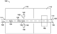
도 1은 본 발명에 따른 예시적인 버핑 시스템의 개략도를 도시하고;
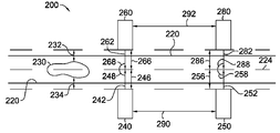
도 2는 본 발명에 따른 예시적인 버핑 시스템의 다른 개략도를 도시하며;
도 3은 본 발명에 따른 예시적인 버핑 시스템의 다른 개략도를 도시하고;
도 4는 본 발명에 따른 예시적인 버핑 시스템의 다른 개략도를 도시하며;
도 5는 본 발명에 따른 예시적인 버핑 시스템의 다른 개략도를 도시하고;
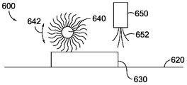
도 6은 본 발명에 따라 버핑된, 팽창된 발포재 물품으로부터 여분의 파티클을 제거하는 예시적인 세척 시스템의 개략도를 도시하며;
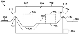
도 7은 본 발명에 따른 다른 시스템의 예를 개략적으로 도시하고;
도 8은 본 발명에 따른 다른 시스템의 예를 개략적으로 도시하며;
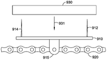
도 9a 및 도 9b는 발포재 물품을 본 발명에 따른 이송 메카니즘으로 유지하는 데에 사용될 수 있는 유지 메카니즘의 예를 도시하고;
도 10은 발포재 물품을 유지 메카니즘으로부터 제거하기 위해 본 발명에 따라 사용될 수 있는 예시적인 제거 메카니즘을 도시하며;
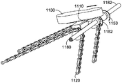
도 11a 내지 도 11d는 발포재 물품을 유지 메카니즘으로부터 제거하기 위해 본 발명에 따라 사용될 수 있는 제거 메카니즘의 예를 도시하고;
도 12a는 본 발명에 따른 유지 메카니즘 및 제거 메카니즘의 예를 도시하며;
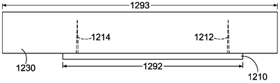
도 12b는 본 발명에 따른 유지 메카니즘 및 발포재 물품의 예를 도시하고;
도 13은 본 발명에 따른 발포재 물품을 프로세싱하는 방법을 도시하며;
도 14는 본 발명에 따라 발포재 물품을 버핑하는 방법을 도시하고;
도 15는 본 발명에 따라 발포재 물품을 프로세싱하는 방법을 도시하며;
도 16은 본 발명에 따라 발포재 물품을 프로세싱하는 방법을 도시하고;
도 17은 본 발명에 따라 발포재 물품을 버핑하는 방법을 도시하며;
도 18은 본 발명에 따라 발포재 물품을 세척하는 세척 시스템을 도시하고;
도 19a는 본 발명의 양태에 따른, 중간 크기 및 형상을 갖는 발포재 물품의 측면 사시도를 도시하며;
도 19b는 본 발명의 양태에 따른, 버핑 작업 및 몰딩 작업 후에 최종 크기와 형상을 갖는 발포재 물품의 측면 사시도를 도시한다.The drawings described herein are for the purpose of presenting only selected examples.
1 shows a schematic diagram of an exemplary buffing system according to the invention;
Figure 2 shows another schematic diagram of an exemplary buffing system according to the present invention;
Figure 3 shows another schematic diagram of an exemplary buffing system according to the present invention;
Figure 4 shows another schematic diagram of an exemplary buffing system according to the present invention;
Figure 5 shows another schematic diagram of an exemplary buffing system according to the present invention;
Figure 6 shows a schematic diagram of an exemplary cleaning system for removing extra particles from an expanded, expanded foam article in accordance with the present invention;
Figure 7 schematically shows an example of another system according to the invention;
Figure 8 schematically shows an example of another system according to the invention;
Figures 9A and 9B illustrate examples of retention mechanisms that can be used to hold a foam material article in a transport mechanism according to the present invention;
Figure 10 illustrates an exemplary removal mechanism that may be used in accordance with the present invention to remove a foam material article from the retention mechanism;
11A-11D illustrate examples of removal mechanisms that may be used in accordance with the present invention to remove foamed article articles from the retention mechanism;
12A shows an example of a retention mechanism and a removal mechanism according to the present invention;
12B shows an example of a holding mechanism and a foamed article according to the present invention;
Figure 13 illustrates a method of processing a foam material article in accordance with the present invention;
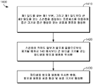
Figure 14 illustrates a method of buffing foamed articles in accordance with the present invention;
Figure 15 illustrates a method of processing a foamed article in accordance with the present invention;
Figure 16 illustrates a method of processing foamed article in accordance with the present invention;
Figure 17 illustrates a method of buffing foamed articles according to the present invention;
Figure 18 shows a cleaning system for cleaning foamed articles according to the present invention;
19A shows a side perspective view of a foamed article having a medium size and shape, according to an aspect of the present invention;
Figure 19b shows a side perspective view of a foamed article having a final size and shape after a buffing operation and a molding operation, in accordance with an aspect of the present invention.
본 발명은 발포재 물품의 프로세싱에 관한 것이다. 본 발명의 양태는 팽창된 발포재 물품의 추가 프로세싱을 위한 준비 시에 발포재 물품의 적어도 일부를 제거하기 위해 팽창된 발포재 물품을 버핑하는 것에 관한 것이다. 발포재를 일반적으로 이용하는 제품의 한 가지 특별한 예는 신발류 물품이다. 신발류 물품은 구두, 부츠, 샌들 등을 포함할 수 있다. 편의상, "구두"라는 용어는 본 명세서에서 신발류 물품의 대표로서 사용된다. 구두는 흔히 에틸렌 비닐 아세테이트("EVA"), 폴리우레탄, 또는 중창이나 구두 구성의 다른 곳에 완충(예컨대, 충격 완화)을 제공하는 다른 유형의 발포재를 이용한다. 본 발명은 몇몇 예에서 구두에 사용하기 위한 EVA 발포재 등의 발포재를 특히 참조하여 설명되어 있지만, 본 발명은 다른 유형의 팽창된 발포재 재료를 이용하여 및/또는 구두 외의 제품에 사용하도록 활용될 수 있다. The present invention relates to the processing of foamed article articles. Aspects of the present invention are directed to buffing an expanded foamed article to remove at least a portion of the foamed article in preparation for further processing of the expanded foamed article. One particular example of a product that commonly uses foam is a footwear article. Footwear items may include shoes, boots, sandals, and the like. For convenience, the term "oral" is used herein as a representative of footwear articles. Shoes commonly use ethylene vinyl acetate ("EVA"), polyurethane, or other types of foam that provide buffering (e.g., shock relaxation) elsewhere in the midsole or shoe configuration. Although the invention has been described with particular reference to foam materials such as EVA foams for use in shoes in some instances, the present invention may be utilized with other types of expanded foam materials and / .
본 발명의 양태에 따르면, 발포재 물품을 프로세싱하는 방법이 제공된다. 상기 방법은 발포재 물품이 궁극적으로 신발류 밑창의 일부로 형성될 수 있는 중간 크기와 중간 형상을 갖는 발포재 물품을 형성하는 것을 포함할 수 있다. 상기 방법은 발포재 물품의 적어도 일부가 제거될 때까지 발포재 물품에 파티클을 투사하는 것을 포함할 수 있고, 파티클은 1.0 내지 5.0 모스(Mohs)의 경도를 가질 수 있다. 상기 방법은 발포재 물품을 최종 형상 및 최종 크기로 형성하는 것을 더 포함할 수 있다. According to an aspect of the present invention, a method of processing a foamed article is provided. The method may include forming a foam material article having a medium and medium shape, wherein the foam material may ultimately be formed as part of the shoe sole. The method may include projecting particles onto the foamed article until at least a portion of the foamed article is removed, and the particles may have a hardness of from 1.0 to 5.0 moles (Mohs). The method may further comprise forming the foamed article article to a final shape and a final size.
본 발명의 추가 양태는 발포재 물품을 버핑하는 방법에 관한 것일 수 있다. 상기 방법은 제1 밀도를 갖는 제1 부분과 제2 밀도를 갖는 표면층을 생성하는 프로세스를 이용하여 중간 크기와 중간 형상을 갖는 발포재 물품을 형성하는 것을 포함할 수 있으며, 여기서 제2 밀도는 제1 밀도보다 클 수 있다. 달리 말해서, 표면층은 예시적인 양태에서 발포재 물품의 내부 부분보다 조밀하다. 상기 방법은 표면층의 적어도 일부가 발포재 물품으로부터 제거될 때까지 발포재 물품에 파티클을 투사하는 것을 포함할 수 있고, 파티클은 20 메시(mesh) 내지 140 메시의 파티클 크기를 갖는다. 또한, 상기 방법은 파티클을 발포재 물품에 투사한 후에, 발포재 물품을 최종 형상과 최종 크기로 형성하는 것을 포함할 수 있다. A further aspect of the invention may relate to a method of buffing foamed article. The method may comprise forming a foam material article having a medium and medium shape using a process of creating a first portion having a first density and a surface layer having a second density, 1 density. In other words, the surface layer is denser than the inner portion of the foamed article in the exemplary embodiment. The method can include projecting particles to the foam material article until at least a portion of the surface layer is removed from the foam material article, wherein the particles have a particle size of 20 mesh to 140 mesh. The method may also include forming the foamed article in a final shape and final size after projecting the particle onto the foamed article.
본 발명의 다른 양태는 프리폼(pre-form) 발포재 물품을 버핑하는 방법에 관한 것이다. 상기 방법은 중간 크기와 중간 형상을 갖는 프리폼 발포재 물품을 형성하는 것을 포함할 수 있고, 여기서 발포재 물품은 신발류 밑창의 일부일 수 있다. 상기 방법은 발포재의 적어도 일부가 프리폼 발포재로부터 제거될 때까지 프리폼 발포재 물품에 파티클을 투사하는 것을 포함할 수 있다. 파티클은 1.0 내지 5.0 모스의 경도와 20 메시 이하 및 140 메시 이상의 파티클 크기를 가질 수 있다. 상기 방법은, 발포재 물품에 파티클을 투사한 후에, 프리폼 발포재 물품을 최종 형상과 최종 크기로 형성하는 것을 더 포함할 수 있다. Another aspect of the invention relates to a method of buffing a pre-form foam article. The method may include forming a preform foam article having a medium and medium shape, wherein the foam article may be part of the soles of the footwear. The method may include projecting particles onto the preform foam article until at least a portion of the foam article is removed from the preform foam article. The particles may have a hardness of 1.0 to 5.0 mos and particle sizes of 20 meshes or less and 140 meshes or more. The method may further include forming the preform foamed article in a final shape and a final size after projecting the particles onto the foamed article.
본 발명에 따른 시스템 및 방법을 이용하여 프로세싱될 수 있는 발포재의 일례는 EVA 발포재이다. 팽창된 EVA 발포재 물품은, EVA 재료에 열 및/또는 압력을 인가하고 재료의 팽창을 유발하는 발포제(blowing agent)를 활성화시켜 팽창된 발포재의 발포재 셀 구조를 형성함으로써 형성될 수 있다. EVA 발포재의 발포제를 활성화시키는 데에 열 및/또는 압력을 인가하는 것은 흔히 발포재 물품의 스킨층으로서 지칭되는 외부층을 EVA 재료 등의 발포재 물품 상에 형성하는 결과를 초래한다. 스킨층은 발포재 물품의 다른 부분의 밀도보다 큰 밀도를 갖는 발포재층일 수 있다. 스킨층은 팽창된 발포재 물품의 형성에 사용되는 몰드와 직접 접촉할 수 있는 층일 수 있다. 몇몇 양태에서, 스킨층은 발포재 물품의 다른 부분보다 형상 및 형태 변화에 더 큰 내성이 있을 수 있다. 특히, 더 큰 밀도를 갖는 발포재 물품의 부분은, 더 작은 밀도를 갖는 발포재 물품의 다른 부분보다 형상 및 형태 변화에 더 큰 내성이 있을 수 있다. An example of a foam material that can be processed using the system and method according to the present invention is an EVA foam material. An expanded EVA foam article can be formed by applying heat and / or pressure to the EVA material and activating a blowing agent that causes the expansion of the material to form the foamed cell structure of the expanded foam. Applying heat and / or pressure to activate the foaming agent of the EVA foam material results in the formation of an outer layer, often referred to as the skin layer of the foam article, on the foam article, such as an EVA material. The skin layer may be a foam layer having a density greater than the density of the other part of the foam article. The skin layer may be a layer that is in direct contact with the mold used to form the expanded foam article. In some embodiments, the skin layer may be more resistant to shape and shape changes than other portions of the foamed article. In particular, the portion of the foamed article having a greater density may be more resistant to changes in shape and shape than other portions of the foamed article having a smaller density.
몇몇 양태에서, 발포재 재료에 대한 열 및/또는 압력의 초기 인가로부터 그리고 열 및/또는 압력의 최종 인가 전에 형성되는 결과적인 발포재 물품은, 발포재 물품 또는 "프리폼"의 중간 구성으로서 지칭될 수 있다. "프리폼"은 또한 최종 형상과 최종 크기로 프로세싱될 수 있다. 본 발명에 따라 처리된 발포재 물품은 EVA 발포재 프리폼일 수 있지만, 반드시 그러한 것은 아니다. 몇몇 양태에서, 프리폼 상의 스킨층은, 예컨대 내구성의 개선 관점에서 몇몇 용례에서 이점을 가질 수 있다. 그러나, 다른 양태에서, 프리폼이 완성품을 형성하기 위해 더 프로세싱되거나 몰딩되는 경우, 스킨층의 존재는 프리폼을 최종 형태로 추가 형성하고 성형하는 것을 방해할 수 있다. 추가 프로세싱 전에 발포재 물품으로부터 스킨층의 일부와 같은, 발포재의 적어도 일부를 제거하는 것이 유리할 수 있다. In some embodiments, the resulting foamed article, which is formed from the initial application of heat and / or pressure to the foamed material and prior to the final application of heat and / or pressure, is referred to as an intermediate configuration of the foamed article or "preform" . The "preform" can also be processed to final shape and final size. The foamed article treated in accordance with the present invention may, but need not, be an EVA foamed preform. In some embodiments, the skin layer on the preform may have advantages in some applications, for example in terms of improving durability. However, in other embodiments, if the preform is further processed or molded to form a finished product, the presence of the skin layer may prevent further shaping and shaping the preform into its final form. It may be advantageous to remove at least a portion of the foam material, such as a portion of the skin layer from the foam material prior to further processing.
본 발명에 따른 발포재 물품에 대한 미립자 이탄산나트륨 등의 파티클의 인가는 발포재 물품의 "버핑"으로 지칭될 수 있다. 버핑은 발포재 물품으로부터 더 조밀한 스킨층과 같은 발포재의 적어도 일부를 제거하는 데 이용될 수 있다. 버핑은 연마제의 수동 인가에 의해 수행될 수 있다. 그러나, 본 발명의 양태에서, 버핑은 발포재 물품의 전체적인 무결성을 저하시키는 일 없이 발포재 물품으로부터 충분한 양의 발포재를 제거하도록 본 명세서에 설명된 시스템 및 방법을 이용하여 수행되는 것이 유리할 수 있다. 발포재 물품의 일부를 수동으로 제거하는 것은 노동 집약적인 동시에 물품으로부터 제거되는 스킨층의 양의 관점에서 불균일하다. 사실상, 본 발명에 따른 시스템 및 방법은 발포재 물품으로부터 필요한 것보다 더 많은 발포재가 제거되는 것을 방지하여 발포재 물품이 그 최종 형상으로 충분하게 형성 및 성형되는 것을 가능하게 할 수 있다. Application of particles such as sodium carbonate to the particulate material for the foam material according to the present invention may be referred to as "buffing" of the foam material. The buffing may be used to remove at least a portion of the foam material, such as a denser skin layer, from the foam material article. The buffing can be performed by manual application of the abrasive. However, in aspects of the present invention, it may be advantageous to perform the buffing using the systems and methods described herein to remove a sufficient amount of foam from the foamed article without degrading the overall integrity of the foamed article . Manually removing a portion of the foamed article is labor intensive and non-uniform in terms of the amount of skin layer removed from the article. In fact, the system and method according to the present invention can prevent more foaming material from being removed than needed from the foamed material article, thereby enabling the foamed material article to be sufficiently formed and shaped into its final shape.
예컨대, 운동화용 중창은, 먼저 비팽창된 EVA 재료에서 발포제를 활성화시켜 프리폼 발포재 물품을 생성함으로써 만들어질 수 있다. 비팽창된 EVA 재료는 EVA, EVA 펠릿, 액체 EVA의 "비스킷(biscuits)" 형태 또는 다른 형태 또는 형상일 수 있다. 프리폼 발포재 물품은 대략 최종 발포재 부품의 원하는 용적 및 형상일 수 있다. 프리폼 발포재 물품은 최종 신발 중창 또는 다른 물품의 원하는 구조적 특성 및/또는 심미적 속성을 갖지 않을 수 있다. 게다가, 프리폼 발포재 물품은 프리폼의 다른 부분의 밀도보다 큰 밀도를 갖는 스킨층을 가질 수 있다. 스킨층은 추가 형성 및 성형에 내성이 있을 수 있다. 본 발명의 양태에서, 시스템 및 방법은 프리폼 발포재 물품으로부터 스킨층의 일부와 같은 발포재의 적어도 일부를 제거할 수 있다. 스킨층의 적어도 일부가 제거된 프리폼 발포재 물품은 그 최종 형상 및 크기로 더 프로세싱될 수 있다. For example, a sneaker can be made by first activating the blowing agent in the unexpanded EVA material to create a preform foamed article. The unexpanded EVA material may be in the form of "biscuits" of EVA, EVA pellets, liquid EVA, or any other shape or shape. The preform foam article may be approximately the desired volume and shape of the final foam article. The preform foam article may not have the desired structural and / or aesthetic properties of the final shoe midsole or other article. In addition, the preform foam article may have a skin layer having a density greater than the density of the other part of the preform. The skin layer may be resistant to further formation and molding. In an embodiment of the invention, the system and method may remove at least a portion of the foam material, such as a portion of the skin layer, from the preform foam material. The preform foamed article in which at least a portion of the skin layer has been removed may be further processed to its final shape and size.
본 발명에 따라 발포재 물품을 버핑하는 데에 사용되는 파티클은 스킨층의 일부와 같은 발포재 물품의 적어도 일부를 제거하는 데에 충분히 효과적인 경질을 나타내도록 선택될 수 있다. 파티클은 또한 발포재 물품에 손상을 주는 것을 피하기에 충분한 연질일 수 있다. 모스 등급으로 측정하면, 파티클의 허용 가능한 경도는 약 1.0 모스 내지 약 5.0 모스, 예컨대 또는 약 1.5 모스 내지 약 2.5 모스일 수 있다. 바람직한 양태에서, 파티클은 1.0 내지 3.0 모스의 경도를 가질 수 있다. 본 발명에 따른 발포재 물품을 버핑하는 데에 사용하도록 선택될 수 있는 재료의 몇몇 예는 대략 2.4 모스의 경도를 갖는 이탄산나트륨(때때로, 베이킹 소다로서 지칭됨); 대략 2.0 모스의 경도를 갖는 드라이 아이스; 소정 온도에서 약 1.5 모스만큼 낮은 경도를 가질 수 있는, 물로 형성된 얼음이다. 얼음 및 드라이 아이스 모두는 파티클이 증발하게 되면 버핑된 물품의 세척이 필요하지 않을 수 있기 때문에, 발포재 물품을 버핑하는 데에 사용하기에 잠재적으로 유리한 유형의 파티클이다. 발포재 물품 상에서 스킨층을 제거하는 데에 이탄산나트륨을 사용하면, 이탄산나트륨이 재활용될 수 있기 때문에 유리할 수 있다. 또한, 이탄산나트륨은, 통상적으로 발포재 물품의 최종 몰딩에 인가되는 열 및/또는 압력에 의해 발포재 물품으로부터 임의의 잔류 미립자 이탄산나트륨이 효과적으로 제거되어, 물품에 대한 임의의 변색 또는 계속되는 손상을 피하며, 물품으로부터 미립자 이탄산나트륨을 세척하는 것이 선택적인 단계, 또는 적어도 제한된 자원을 필요로 하는 단계가 되게 하기 때문에 유리할 수 있다. The particles used to buff the foamed article in accordance with the present invention may be selected to exhibit a hardness sufficiently effective to remove at least a portion of the foamed article, such as a portion of the skin layer. The particles may also be soft enough to avoid damaging the foam material. As measured by the moss grade, the acceptable hardness of the particles may be from about 1.0 mos to about 5.0 mos, e.g., or from about 1.5 mos to about 2.5 mos. In a preferred embodiment, the particles may have a hardness of 1.0 to 3.0 mos. Some examples of materials that may be selected for use in buffing foamed articles according to the present invention include sodium bicarbonate (sometimes referred to as baking soda) having a hardness of about 2.4 mos; Dry ice having a hardness of about 2.0 mos; It is water-formed ice that can have a hardness as low as about 1.5 mos at a given temperature. Both ice and dry ice are types of particles that are potentially beneficial for use in buffing foam articles because they may not require washing of the buffered article once the particles have evaporated. The use of sodium bicarbonate to remove the skin layer on the foamed article may be advantageous because the sodium carbonate can be recycled. In addition, this sodium carbonate is effective for effectively removing sodium carbonate from any remaining fine particles from the foamed article due to the heat and / or pressure applied to the final molding of the foamed article so as to avoid any discoloration or subsequent damage to the article. And it may be advantageous to wash particulates from the article with sodium carbonate in an optional step, or at least a step that requires limited resources.
본 발명에 따른 버핑 시스템은 발포재 물품을 버핑하는 데에 사용되는 이동 파티클을 둘러싸는 챔버를 포함할 수 있다. 상기 이동 파티클은 순환 시스템을 이용하여 이동될 수 있다. 발포재 물품은 컨베이어 벨트 등의 이송 메카니즘에 의해 챔버를 통과하여 이동될 수 있다. 본 발명에 따른 버핑 시스템의 다른 예는 파티클을 챔버 내에 도입하는 하나 이상의 분배기를 제공할 수 있다. 몇몇의 예에서, 복수 개의 분배기가, 버핑될 발포재 물품 상에 파티클을 직접적으로 또는 간접적으로 투사할 수 있다. 그러한 분배기는, 예컨대 원하는 지점으로부터 하나 이상의 발포재 물품에 대해 파티클을 원하는 속도 및/또는 힘으로 투사하도록 공기 압력을 이용하는 노즐을 포함할 수 있다. 공기 압력을 이용하여 파티클을 투사하는 다수의 분배기들은, 버핑될 팽창된 발포재 물품의 표면에 거의 수직인 각도로 파티클을 추진시키도록 동시에 지향될 수 있다. 이탄산나트륨 파티클이 분사된 챔버의 영역 및/또는 다수의 분배기는 챔버 내의 버핑 영역을 포함할 수 있다.The buffing system according to the present invention may include a chamber surrounding moving particles used to buff the foamed article. The moving particles may be moved using a circulation system. The foamed article can be moved through the chamber by a transport mechanism such as a conveyor belt. Another example of a buffing system according to the present invention may provide one or more distributors for introducing particles into the chamber. In some examples, a plurality of dispensers may project particles directly or indirectly onto the foamed article to be buffered. Such a dispenser may include nozzles that utilize air pressure to project the particles at a desired velocity and / or force, e.g., for one or more foam articles from a desired point. A plurality of dispensers that project particles using air pressure can be simultaneously directed to propel the particles at an angle substantially normal to the surface of the expanded foamed article to be buffered. The area of the chamber in which the sodium carbonate particles are injected and / or the plurality of distributors may comprise a buffer area in the chamber.
원한다면, 공기 송풍기(air blower), 브러시, 헹굼 시스템, 진동 시스템 또는 임의의 다른 메카니즘 또는 이러한 메카니즘들의 조합과 같은 세척 메카니즘이 이용되어, 챔버에서 빠져나가기 전에 발포재 물품으로부터 미립자 이탄산나트륨과 같은 여분의 파티클을 제거할 수 있다. 세척 시스템은 파티클이 투사되는 버핑 챔버와 별개로 세척 챔버 내에 제공될 수 있다. 대안으로, 단일 챔버는, 버핑을 위한 구역과, 단일 챔버 내에 세척 구역을 포함할 수 있는 세척 메카니즘이 차지하거나 접근하는 챔버의 부분을 가질 수 있다. 다른 예로서, 본 발명에 따른 시스템 및 방법은 파티클을 발포재 물품에 인가하기 위한 챔버 및 여분의 파티클을 발포재 물품으로부터 세척하기 위한 챔버를 물리적으로 별개로 제공할 수 있다. 본 발명에 따른 시스템 및 방법은 또한 분배기에 의해 사용된 미립자 이탄산나트륨과 같이 이미 분배된 파티클을 포집하여 이를 재사용하게 할 수 있는 재활용 메카니즘을 제공할 수 있다. If desired, a cleaning mechanism such as an air blower, brush, rinse system, vibration system or any other mechanism or combination of such mechanisms may be used to remove particulates from the foamed article prior to exiting the chamber, You can remove particles. The cleaning system can be provided in the cleaning chamber separately from the buffing chamber into which the particles are projected. Alternatively, the single chamber may have a zone for buffing and a portion of the chamber occupying or approaching a cleaning mechanism that may include a cleaning zone in a single chamber. As another example, a system and method according to the present invention may physically provide a chamber for applying particles to a foam material article and a chamber for cleaning extra particles from the foam material article. The system and method according to the present invention can also provide a recycling mechanism that allows the particulates used by the distributor to collect and reuse already dispensed particles, such as sodium carbonate.
이제, 도 1을 참조하면, 팽창된 발포재 EVA 물품 등의 발포재 물품을 버핑하기 위한 예시적인 시스템(100)이 도시되어 있다. 도 1의 예에 도시된 바와 같이, 시스템(100)은 입구(111) 및/또는 출구(114)를 갖는 챔버(110)를 포함할 수 있지만, 단일의 결합형 입구와 출구 및/또는 다수의 입구 및/또는 출구가 챔버에 대해 본 발명에 따라 사용될 수 있다. 이송 메카니즘(120)은 팽창된 EVA 물품 등의 일련의 발포재 물품을 대체로 챔버 입구(111)로부터 챔버 출구(114)로 진행하는 방향(122)인 경로(124)를 따라 챔버(110)를 통해 운반할 수 있다. 도 1의 예는 실질적으로 선형의 이동 경로(124)를 도시하고 있지만, 상이한 예에서, 이송 메카니즘(120) 등의 이송 메카니즘은 발포재 물품을 챔버(110)와 같은 챔버를 통해 불규칙형 경로, 비선형 경로, 곡선형 경로, 지그재그형 경로, 또는 다른 유형의 경로로 운반할 수 있다. 이송 메카니즘(120)은 물품을, 예컨대 프롱(prong) 상에, 클립 상에, 랙(rack) 상에, 바스킷 내에, 또는 임의의 다른 유형의 시스템에서 운반하는 하나 이상의 컨베이어 벨트, 체인, 또는 다른 시스템을 포함할 수 있다. 몇몇 예에서, 발포재 물품은, 운반을 위해 발포재 물품을 착탈 가능하게 유지하기 위해 발포재 물품을 관통하는 복수 개의 프롱 상에 유지될 수 있다. Referring now to FIG. 1, an
복수 개의 발포재 물품은 이송 메카니즘(120)에 의해 챔버(110)를 통과하여 운반될 수 있다. 도 1의 본 발명에서, 제1 물품(130), 제2 물품(132), 및 제3 물품(134)이 도시되어 있다. 도 1에서 확인될 수 있는 바와 같이, 본 예에서, 각각의 발포재 물품(130, 132, 134)의 종방향 축선은 물품들의 경로(124)와 실질적으로 정렬된다. 그러나, 다른 배향, 또는 전혀 특별하지 않은 배향이 본 발명에 따른 발포재 물품에 사용될 수 있다. A plurality of foam articles may be conveyed through the
또한 도 1을 참조하면, 버핑 챔버(110) 내에서, 발포재 물품(130, 132, 134)이 이송 메카니즘(120)에 의해 챔버(110)를 통과하여 운반될 때에, 하나 이상의 분배기가 발포재 물품 상에 파티클을 투사할 수 있다. 예컨대, 제1 분배기(140)가 발포재 물품(130)의 한 종방향 측부로부터 파티클 유체 스트림(150)을 투사할 수 있고, 제2 분배기(142)가 발포재 물품(130)의 대향하는 종방향 측부로부터 제2의 파티클 유체 스트림(152)을 투사할 수 있다. 여기서 사용되는 바와 같이, "유체"라는 용어는 액체, 가스, 및/또는 공기를 지칭할 수 있다. 도 1의 예에 도시된 예는 이송 메카니즘(120)의 대향 측부에 배치되는 오직 2개의 분배기(140, 142)만을 이용하지만, 다른 개수, 구성, 및 배향의 분배기가 본 발명에 따라 사용될 수 있고, 대안적인 구성 또는 추가적인 구성의 몇몇 예가 아래에 설명되어 있다. 파티클을 발포재 물품에 인가하는 데에 사용되는 적어도 하나의 분배기의 구성, 개수, 및 특성은 버핑될 물품의 크기 및/또는 구성, 버핑될 물품의 부분, 원하는 버핑 정도 등을 기초로 할 수 있다. 예컨대, 분배기는, 추가 성형을 거치는 발포재 물품의 부분에 파티클을 인가하지만, 추가 성형을 거치지 않는 발포재 물품의 부분에는 미립자 이탄산나트륨을 인가하지 않도록 위치 설정될 수 있다. 그러한 예에서, 분배기는 이를테면 파티클을 발포재 물품의 저부가 아니라 발포재 물품의 측부들 및 상부에 도포할 수 있다. 그러나, 본 발명에 따르면, 분배기는 파티클을 발포재 물품의 전체 표면에 걸쳐 인가하도록 구성될 수 있다. 1, when the foamed
분배기(140, 142)에 의해 인가되는 파티클(150, 152)의 유형은 발포재 물품(130, 132, 134)을 버핑할 때에 원하는 경도, 크기, 재활용성, 또는 다른 특성을 기초로 하여 변경될 수 있다. 예컨대, 파티클은 얼음(약 1.5 모스만큼 낮은 경도), 드라이 아이스(약 2.0 모스의 경도), 및/또는 이탄산나트륨(약 2.4 모스의 경도), 또는 약 1.0 내지 3.0 모스 사이 또는 약 1.5 내지 2.5 모스 사이의 경도를 갖는 임의의 다른 재료를 포함할 수 있다. 쉽게 재사용 가능한 파티클 유형을 원한다면, 20 메시 크기와 같이 비교적 큰 크기의 미립자 이탄산나트륨은, 파티클의 크기가 140 메시와 같은 최소 크기 미만으로 떨어질 때까지 사용 및 재사용될 수 있다. 다른 한편으로, 발포재 물품의 표면 상에 남아 있는 얼음 또는 드라이 아이스는 증발에 의해 제거될 수 있지만, 미립자 이탄산나트륨은 버핑 후에 파티클을 물품으로부터 제거하기 위해 세척 메카니즘을 필요로 할 수 있다. 본 발명에 따른 시스템 및 방법의 다른 예는 미립자 이탄산나트륨의 사용에 대해 설명되지만, 다른 유형의 미립자 물질이 사용될 수 있다. The types of
예시적인 양태에서, 파티클의 크기는 다수의 인자들에 의해 제약된다. 예컨대, 140 메시와 같이 더 작은 크기의 제약이 다수의 인자들을 기초로 하여 결정된다. 예컨대, 140 메시보다 작은 파티클은 소정의 압력 및 유량에서 하나 이상의 노즐 내에서 무리를 이룰 수 있어 노즐이 파티클을 비효율적으로 분배하게 하거나 심지어는 파티클을 투사할 수 없게 노즐을 폐색시킨다. 또한, 예시적인 시나리오에서, 파티클의 크기가 예컨대 140 메시로 감소됨에 따라, 더 큰 파티클에 의해 달성되는 동일한 버핑 결과를 갖기 위해 더 큰 전체 용적의 파티클 재료가 요구되는 것으로 판명되었다. 크기 범위의 다른 한계에 있어서, 파티클의 크기가 소정의 값을 초과함에 따라, 버핑 프로세스는 예시적인 양태에서 덜 균일한 버핑 마무리를 초래하는 것으로 판단된다.In an exemplary embodiment, the size of the particle is constrained by a number of factors. For example, constraints of smaller size, such as 140 mesh, are determined based on a number of factors. For example, particles smaller than 140 mesh can clump within one or more nozzles at a given pressure and flow rate, thereby occluding the nozzles inefficiently distributing the particles or even preventing the particles from projecting. Also, in an exemplary scenario, it has been found that as the particle size is reduced to, for example, 140 meshes, a larger total volume of particle material is required to have the same buffing results achieved by the larger particles. For other limits of the size range, it is determined that as the size of the particles exceeds a predetermined value, the buffing process results in a less uniform buffing finish in the exemplary embodiment.
도 1을 계속 참조하면, 세척 메카니즘(160)이 세척 챔버(112) 내에 마련되어 있지만, 세척 메카니즘(160)은 대안으로 버핑 및 세척을 위해 단일 챔버(110) 내에 배치될 수 있다. 세척 메카니즘(160)은 분배기(140, 142)가 파티클을 물품(130, 132, 134)에 대해 인가한 후에 발포재 물품(130, 132, 134)으로부터 미립자 이탄산나트륨과 같은 잉여 파티클을 제거할 수 있다. 세척 시스템(160)은, 물을 물품(130, 132, 134) 상에 분사하거나 붓는 물 분사 시스템을 포함할 수 있지만, 다른 세척 메카니즘이 세척 시스템(160)으로서 사용될 수 있다. 예컨대, 발포재 물품(130, 132, 134)으로부터 잉여 파티클을 제거하기 위해 이동하는 공기를 이용하는 팬 또는 다른 공기 송풍 장치가 사용될 수 있다. 다른 예에서, 발포재 물품이 물 아래에 침수되게 하는 침수 메카니즘이 세척 시스템(160)에 대해 사용될 수 있다. 추가의 예에서, 세척 시스템(160)은 여분의 파티클을 제거하는 이동 브러시 또는 회전 브러시를 포함할 수 있지만, 세척 시스템(160)은 헹굼 시스템, 진동 시스템, 및/또는 장치들의 조합과 같이 다른 유형의 장치를 더 포함할 수 있다. 세척 시스템(160)의 몇몇 비제한적인 다른 예가 아래에서 설명된다. 1, although the
효과적으로, 도 1에 도시된 예시적인 시스템(100)은 지나치게 두꺼운 스킨을 여전히 갖고 있는 팽창된 EVA 발포재 물품과 같은 발포재 물품(130, 132, 134)이 이송 메카니즘(120) 상의 입구(111)를 통해 챔버(110)에 진입하게 한다. 이때, 이송 메카니즘(120)은, 물품(130, 132, 134)을 일 방향(122)의 경로(124)를 따라 이송하여 물품(130, 132, 134)이 소정 위치 또는 일련의 위치에 있게 함으로써 이들 물품(130, 132, 134) 상에 미리 형성된 스킨, 예컨대 원하는 셀 구조를 물품에 대해 형성하도록 발포제를 활성화시킬 때에 형성된 스킨을 부분적으로 또는 전체적으로 제거하도록 분배기(140, 142)가 파티클(150, 152)을 물품(130, 132, 134)에 분배하게 한다. 파티클(150, 152)의 인가 후에, 이송 메카니즘(120)은 여분의 파티클 중 적어도 일부를 물품(130, 132, 134)으로부터 제거할 수 있는 세척 시스템(160)으로 물품(130, 132, 134)을 더 이동시킬 수 있다. 그 후에, 이송 메카니즘(120)은 발포재 물품(130, 132, 134)을 최종 형태로 몰딩하는 것 또는 물품(130, 132, 134)의 다른 프로세싱과 같은 임의의 추가 프로세싱을 위해 출구(114)를 통해 챔버(110) 밖으로 물품(130, 132, 134)을 이동시킬 수 있다. The
이제, 도 2를 참조하면, 발포재 물품(230)을 버핑하기 위한 시스템(200)의 다른 예가 도시되어 있다. 도 2는 특히 발포재 물품(230)으로부터 제거되는 스킨의 양을 결정하는 데 사용될 수 있는 일부 버핑 파라미터를 예시한다. 도 2에 도시된 바와 같이, 제1 분배기(240)는 이송 메카니즘(220)에 의해 생성되는 이동 경로(224)에 대해 제1 각도(248)를 갖는 제1 방향으로 미립자 이탄산나트륨 등의 파티클 스트림(242)을 투사할 수 있다. 미립자 이탄산나트륨의 제1 스트림(242)은 또한 예정된 힘 및/또는 예정된 속도로 투사될 수 있다. 제1 분배기(240)의 위치는 또한 분배기(240)로부터 이송 메카니즘(220)의 중앙까지의 거리(246) 및 분배기(240)로부터 발포재 물품(230)의 표면까지의 거리(234)를 결정할 수 있다. 유사하게, 제2 분배기(250)가 미립자 이탄산나트륨 등의 파티클의 제2 스트림(252)을 이동 경로(224)에 대해 제2 각도(258)로 투사할 수 있고, 이때 제2 분배기(250)는 이송 메카니즘(220)의 중앙으로부터의 거리(256) 및 이 경우에 발포재 물품(230)으로부터의 거리(234)를 갖는다. 제1 각도(248)와 제2 각도(258)는 30도 내지 120도 사이에서 변할 수 있다. 제1 분배기(240)와 제2 분배기(250)는 발포재 물품(230)의 길이의 일부로부터 발포재 물품(230)의 길이의 수배까지 달할 수 있는 거리(290)만큼 떨어져 있을 수 있다. 제1 분배기(240)와 제2 분배기(250)로부터 이송 메카니즘(220)의 반대쪽에서는, 이송 메카니즘(220)이 발포재 물품(230)을 이동시킬 때에, 제3 분배기(260)와 제4 분배기(280)가 미립자 이탄산나트륨 등의 파티클을 대안으로/추가적으로 투사할 수 있다. 제3 분배기(260)는 이송 메카니즘(220)의 중앙까지의 제1 거리(266)로부터 그리고 제3 각도(268)로 미립자 이탄산나트륨의 제3 스트림(262)을 투사할 수 있다. 제4 분배기(280)는 이송 메카니즘(220)의 중앙까지의 제4 거리(286)로부터 그리고 제4 각도(288)로 미립자 이탄산나트륨의 제4 스트림(282)을 투사할 수 있다. 제3 분배기(260)와 제4 분배기(280)는 발포재 물품(230)의 길이의 일부로부터 발포재 물품(230)의 길이의 수배까지 달할 수 있는 거리(292)만큼 떨어져 있을 수 있다. 도 2에 예시된 예에서, 제3 분배기(260)와 제4 분배기(280) 모두는, 이송 메카니즘(220)이 제3 분배기(260)와 제4 분배기(280)를 지나서 발포재 물품(230)을 운반할 때에 발포재 물품(230)의 표면으로부터 거리(232)에 배치된다. Referring now to FIG. 2, another example of a
도 2의 예는 4개의 분배기(240, 250, 260, 280)의 대칭적인 배치를 예시하고 있지만, 본 발명은 미립자 이탄산나트륨의 분배기들의 비대칭적인 배치를 이용할 수 있다. 예컨대, 분배기는 이송 메카니즘(220) 등의 이송 메카니즘의 중앙으로부터 다양한 거리에 위치할 수 있고, 발포재 물품(230)의 이동 경로(224)에 대해 상이한 각도를 형성하도록 배치될 수 있으며, 발포재 물품(230)의 표면으로부터 상이한 거리에 배치될 수 있고, 및/또는 발포재 물품 또는 일련의 발포재 물품들의 소정의 측부, 구역, 위치 등에 많은 또는 적은 미립자 이탄산나트륨을 집중시키도록 메카니즘(220) 등의 이송 메카니즘 및/또는 물품(230) 등의 발포재 물품 주위에 불균일하게 분포될 수 있다. 또한, 존재하더라도, 존재하는 모든 분배기들이 미립자 이탄산나트륨을 동시에 적극적으로 투사할 필요는 없다. While the example of FIG. 2 illustrates the symmetrical arrangement of the four
이제, 도 3을 참조하면, 본 발명에 따른 시스템(300)의 다른 예의 개략적인 단면도가 도시되어 있다. 도 3의 예에서, 발포재 물품(330)은, 제1 노즐(341)과 제2 노즐(343)로부터 미립자 이탄산나트륨 등의 파티클을 투사하는 제1 측방향 분배기(340)와, 제1 노즐(351)과 제2 노즐(353)로부터 미립자 이탄산나트륨 등의 파티클을 투사하는 제2 측방향 분배기(350) 사이로, 그리고 제1 노즐(361)과 제2 노즐(363)로부터 미립자 이탄산나트륨 등의 파티클을 투사하는 제1 수직 방향 분배기(360) 아래로 물품(330)이 통과하도록 이송 메카니즘(320)에 의해 운반된다. 사실상, 이송 메카니즘(320)이 미립자 이탄산나트륨이 물품과 접촉할 수 있는 버핑 구역을 통해 발포재 물품(330)을 운반할 때에, 시스템(300)은, 발포재 물품(330)을 버핑하도록, 예컨대 팽창된 발포재 물품으로부터, 좌측에서, 우측에서, 그리고 위쪽에서 스킨을 제거하도록, 미립자 이탄산나트륨을 분배한다. 도 3의 예에 도시된 바와 같이, 분배기(340)는 노즐(341, 343)로부터 일 거리(344)에서 그리고 물품(330)을 향해 일 각도(346)로 미립자 이탄산나트륨의 스트림(342)을 분배할 수 있다. 분배기(350)는 노즐(351, 353)로부터 일 거리(354)에서 그리고 물품(330)을 향해 일 각도(356)로 미립자 이탄산나트륨의 스트림(352)을 분배할 수 있다. 물품(330) 위쪽에서 작동하는 분배기(360)는 노즐(361, 363)로부터 일 거리(364)에서 그리고 물품(330)에 대해 일 각도(366)로 미립자 이탄산나트륨의 스트림(362)을 분배할 수 있다. 다양한 분배기(340, 350, 360)가 물품(330)에 미립자 이탄산나트륨을 투사하는 각도(346, 356, 366)뿐만 아니라 거리(344, 354, 364)는 모든 분배기에 대해 동일할 수 있거나, 여러 분배기들에 대해 상이할 수 있거나, 예컨대 버핑 중에 분배기(340, 350, 360)를 이동시킴으로써 및/또는 버핑 중에 이동 물품(330) 및/또는 이송 메카니즘(320)을 이동시킴으로써 물품(330)과 같은 물품의 버핑 중에 변경될 수 있다. Referring now to FIG. 3, there is shown a schematic cross-sectional view of another example of a
이제, 도 4를 참조하면, 물품(430) 등의 발포재 물품을 버핑하는 시스템(400)의 다른 예가 예시되어 있다. 도 4의 예에서, 이송 메카니즘(420)은 상부(411), 저부(413), 및 벽(415)이 있는 챔버(410)를 통과하는 방향(422)으로 물품(430)을 이동시킬 수 있다. 챔버(410)는, 챔버(410)를 별개의 버핑 챔버(493)와 세척 챔버(495)로 분할하는 내벽(491)을 제공할 수 있다. 이송 메카니즘(420)은 입구(412)를 통해 챔버(410) 내로 물품(430)을 도입하고 궁극적으로는 출구(414)를 통해 챔버(410)로부터 물품(430)을 제거할 수 있다. 챔버(410) 내에서, 미립자 이탄산나트륨은 제1 분배기(440)와 제2 분배기(450)에 의해 물품(430)을 향해 투사될 수 있지만, 본 예에서 예시된 것보다 더 많거나 적은 분배기가 이용될 수 있다. 미립자 이탄산나트륨 전달 시스템(490)은 연결부(494)를 통해 제1 분배기(440)로부터 분배하도록 미립자 이탄산나트륨을 제공할 수 있고 연결부(495)를 통해 제2 분배기(450)로부터 분배하도록 미립자 이탄산나트륨을 제공할 수 있다. 제1 분배기(440)는 미립자 이탄산나트륨을 분배할 수 있는 제1 노즐(441)과 제2 노즐(443)을 가질 수 있다. 제2 분배기(450)는 미립자 이탄산나트륨을 분배할 수 있는 제1 노즐(451)과 제2 노즐(453)을 가질 수 있다. 미립자 이탄산나트륨을 분배기(440, 450)로 전달하는 임의의 수단이 본 발명에 따라 사용될 수 있지만, 압축 공기 및/또는 송풍기를 이용하여 달성될 수 있는 것과 같은 공기 압력이 파티클의 운반 및 투사에 사용될 수 있다. Referring now to FIG. 4, another example of a
선택적으로 도 4의 예에 도시된 바와 같이 경사형 측부 또는 깔때기형 측부를 갖는 통(416)은, 이미 분배된 미립자 이탄산나트륨(470)을 모으기 위해 분배기(440, 450) 아래에서 챔버(410) 내에 배치될 수 있다. 이미 분배된 미립자 이탄산나트륨은, 예컨대 이미 분배된 미립자 이탄산나트륨(470)을 전달 시스템(490)으로 복귀시키도록 진공 튜브 등의 흡기 메카니즘(480)을 이용함으로써 다른 발포재 물품을 버핑하는 데에 재사용될 수 있다. 통(416)은 시스템(400)에 의한 버핑에 사용하기에 충분히 큰 미립자 이탄산나트륨(470) 저장조를 제공함에 있어서 충분한 크기를 가질 수 있지만, 본 발명의 범위 내에서 미립자 이탄산나트륨의 추가적인/대안적인 저장조가 마련될 수 있다. 미립자 이탄산나트륨의 재사용은, 일례에서 문턱값 크기 미만의 파티클을 문턱값 크기 초과의 파티클과 분리시키기 위해 회전 효과에 의존하는 사이클론 분리 및/또는 필터 시스템을 통합할 수 있다. 예컨대, 140 메시(0.105 mm) 미만 또는 60 메시(0.250 mm) 미만의 파티클 크기를 갖는 파티클이 폐기될 수 있다. 이탄산나트륨 파티클의 초기 크기는, 예컨대 20 매시(0.841 mm) 또는 40 메시(0.420 mm)일 수 있고, 이에 따라 폐기되기 전에 미립자 이탄산나트륨은 수차례 재사용되게 된다. 추가적으로 예상되는 파티클의 범위는 20 메시 내지 140 메시, 20 메시 내지 80 메시, 또는 40 메시 내지 80 메시를 포함한다. 따라서, 전달 시스템(490)은, 다음의(또는 현재의) 버핑 작업에서 재사용되기에 충분한 크기인 파티클을 분류하기 위해 사이클론 분리를 이용하는 사이클론 장치로 구성될 수 있다는 것이 예상된다. Alternatively, as shown in the example of FIG. 4, a
세척 시스템은 분배기(440, 450)에 의한 버핑 후에 물품(430) 상에 남아 있는 임의의 미립자 이탄산나트륨을 궁극적으로 제거하도록 물(462)을 분사하는 물 분사 노즐(460)을 포함할 수 있다. 여분의 미립자 이탄산나트륨(471)은 궁극적으로 제2 통(417)의 바닥으로 떨어질 수 있는데, 이 제2 통은 또한 선택적인 재사용을 위해 사용 후 미립자 이탄산나트륨(471)의 포집을 용이하게 하도록 경사형 측부를 가질 수 있다. 재활용 흡기 메카니즘(도시 생략)은 분배기(440, 450)에 의한 다음 번 재사용을 위해 여분의 미립자 이탄산나트륨(471)을 미립자 이탄산나트륨 전달 시스템(490) 내로 재도입시킬 수 있다. 재활용 메카니즘은 진공 흡기 호스, 스트래핑 메카니즘(scraping mechanism) 등을 포함할 수 있다. 다른 예에서, 이미 투사된 미립자 이탄산나트륨의 재활용은, 세척 시스템에 의해 제거된 또는 단순히 물품(430) 등의 발포재 물품과 관련하여 이전에 쓰이지 않은 여분의 미립자 이탄산나트륨을 수동으로 또는 자동화 방식으로 주기적으로 포집함으로써 달성될 수 있다. 재활용 메카니즘은 도 4에 도시된 예에서 한쪽 통 또는 양쪽 통(416, 417)으로부터 이미 분배된 미립자 이탄산나트륨을 포집할 수 있다. The cleaning system may include a
이제, 도 5를 참조하면, 본 발명에 따라, 팽창된 EVA 발포재 물품 등의 발포재 물품을 프로세싱하기 위한 시스템(500)의 다른 개략도가 예시되어 있다. 준비 시스템(580)은 본 예와 관련하여 설명되는 팽창된 EVA 발포재 물품, 또는 다른 유형의 발포재 물품을 생성할 수 있다. 물품(530) 등의 팽창된 EVA 발포재 물품은 발포제를 활성화시킴으로서 팽창되고 그 후에 준비 시스템(580)에 의해 원하는 크기 및 형상으로 안정화될 수 있다. 팽창된 EVA 발포재 물품을 제공하는 시스템(들)(580)은 열 프레스, EVA 펠릿 분배 시스템, 안정화 시스템, 오븐, 냉각 스테이션 등을 이용할 수 있다. 준비 시스템(580)에 의해 형성되는 물품(530)은, 마무리 시스템(590)에 의해 물품이 쉽게 형성되는 것을 방해하는 스킨을 가질 수 있다. Referring now to FIG. 5, another schematic view of a
이송 메카니즘(520)은 준비 시스템(580)으로부터 팽창된 EVA 발포재 물품(530)을 수신하여 물품(530)을 화살표(522)에 의해 지시되는 방향으로 챔버(510)를 통해 운반할 수 있다. 챔버(510)는 예시적인 미립자 이탄산나트륨 분배기(541)와 같은 복수 개의 파티클 분배기를 갖는 버핑 구역(540)을 포함할 수 있다. 물품(530) 상에 남아 있는 임의의 여분의 미립자 이탄산나트륨은 클리너(cleaner; 561)를 제공할 수 있는 세척 구역(560)에서 제거될 수 있다. 버핑 구역(540)과 세척 구역(560)은 별개의 챔버를 포함할 수 있거나, 또는 단일 챔버의 상이한 영역들을 포함할 수 있다. 클리너(561)는, 예컨대 물품(530)으로부터 여분의 미립자 이탄산나트륨을 제거하는 물 세척 시스템, 송풍기, 브러시, 진동 시스템 등을 포함할 수 있다. 시스템(500)은 연결부(552)를 통해 버핑 구역(540)에 미립자 이탄산나트륨을 제공할 수 있는 저장조(550)를 더 포함할 수 있다. 저장조(550)는 신선하고 미사용된 미립자 이탄산나트륨, 재사용을 위해 포집된, 이미 분배된 미립자 이탄산나트륨, 또는 이들 2개의 조합을 포함할 수 있다. 연결부(552)는, 예컨대 튜브 또는 호스를 포함할 수 있다. 연결부(552)는 투사 메카니즘(554)에 의해 인가된 힘의 작용 하에 저장조(550)로부터 미립자 이탄산나트륨을 운반할 수 있는데, 투사 메카니즘은, 예컨대 압축 공기, 송풍 공기, 또는 다른 수단을 이용하여 미립자 이탄산나트륨을 저장조(550)로부터 세척 구역(540)의 분배기(541)로 운반하고 분배기(541)로부터 투사될 때에 미립자 이탄산나트륨에 원하는 크기의 힘을 부여할 수 있다. 세척 구역(560) 내에서 클리너(561)에 의한 세척 후에, 물품(530)은 마무리 시스템(590)에 의한 추가 프로세싱을 위해 챔버(510)에서 빠져나갈 수 있다. 마무리 시스템(590)에 의해 수행되는 추가 프로세싱은, 예컨대 버핑 후에 팽창된 EVA 발포재 물품을 열 및/또는 압력의 인가를 이용하여 최종 형상 및/또는 구성으로 최종 몰딩하는 것을 포함할 수 있다. 시스템(500)에 의해 물품(530) 상의 스킨의 일부 또는 전부를 제거하는 것은, 팽창된 EVA 발포재 물품의 최종 구성을 시스템(590)에 의해 형성하는 것을 용이하게 할 수 있다. The
이제, 도 6을 참조하면, 본 발명에 따른 시스템 및 방법에 사용될 수 있는 예시적인 세척 시스템(600)이 예시되어 있다. 도 6의 예의 세척 시스템(600)은 이송 메카니즘(620)에 의해 이동되는 발포재 물품(630)의 표면으로부터 여분의 미립자 이탄산나트륨을 제거하기 위해 화살표(642)에 의해 지시되는 바와 같이 하나 이상의 방향으로 회전하는 브러시(640)를 선택적으로 이용할 수 있다. 도 6의 예에는 예시되어 있지 않지만, 복수 개의 분배기를 사용할 수 있는 버핑 구역은, 예컨대 팽창된 EVA 발포재 물품의 외측으로부터 스킨을 전체적으로 또는 부분적으로 제거하기 위해 물품(630)의 외측을 미리 버핑했을 수 있다. 회전하는 브러시(640)에 추가하여 또는 그 대신에, 물 분사 노즐(650)은 물(652)을 이용하여 발포재 물품(630)의 표면으로부터 여분의 미립자 이탄산나트륨을 제거할 수 있다. 브러시(640)와 물 분사 노즐(650) 모두가 본 예에 예시되어 있지만, 한쪽 또는 양쪽이 생략되거나, 또는 심지어는 물품(630)의 표면으로부터 여분이 미립자 이탄산나트륨을 제거하도록 공기 송풍기, 수조, 물 분사 메커니즘, 진동 메카니즘 등의 다른 세척 메카니즘으로 대체될 수 있다. 2개 이상의 브러시(640) 및/또는 물 분사 노즐(650)이 본 예에 따른 세척 시스템(600)에 사용될 수 있고, 이송 메카니즘(620)에 의해 운반되는 물품(630)의 이동 방향은, 도 6의 예에서, 브러시(640) 또는 송풍기(650) 중 어느 한쪽이 먼저 팽창된 EVA 발포재 물품(630)과 조우할 수 있도록 변경될 수 있다. Turning now to FIG. 6, an
이제, 도 7을 참조하면, 본 발명에 따른 예시적인 시스템(700)의 다른 개략도가 예시되어 있다. 도 7의 예에서, 상부, 저부, 및 측부를 갖는 챔버(710)로 인해, 이송 메카니즘(720)이 발포재 물품(730)을 입구(712)를 통해 챔버(710) 내로, 제1 부분(742)과 제2 부분(762) 사이에서 개구(752)를 통해, 그리고 출구(714)를 통해 챔버(710) 밖으로 운반할 수 있다. 챔버(710)는 챔버(710)의 제1 부분(742) 내에 버핑 구역(740)을 가질 수 있다. 제1 부분(742)은 내부 격벽(750)에 의해 챔버(710)의 제2 부분(762)으로부터 분리될 수 있다. 제1 부분(742) 내의 버핑 구역(740)은, 예컨대 본 명세서에서 설명된 것과 같은 미립자 이탄산나트륨의 하나 이상의 분배기를 제공할 수 있다. 챔버(710)는 또한 선택적으로 챔버(710)의 제2 부분(762) 내에 세척 구역(760)을 제공할 수 있다. 세척 구역(760)은 물품(730)으로부터 여분의 미립자 이탄산나트륨을 제거하기 위해 이동 공기, 브러시, 물, 진동 메카니즘, 또는 다른 프로세스를 이용할 수 있다. 도 7의 예에 도시된 바와 같이, 챔버(710)의 입구(712)와 출구(714)는 버핑 구역(740)과 세척 구역(760)이 배치되는 챔버(710)의 부분에 대해 높게 마련되어 있을 수 있다. 예컨대, 이송 메카니즘(720)은 제1 높이(722)에서 입구(712)를 통해 챔버(710) 내로 물품(730)을 운반할 수 있고 제2 높이(724)에서 출구(714)를 통해 챔버(710) 밖으로 물품(730)을 운반할 수 있다. 제1 높이(722)와 제2 높이(724)는 동일할 수도 있고 상이할 수도 있다. 한편, 이송 메카니즘(720)은 제3 높이(726)에서 버핑 구역(740)을 통해 물품(730)을 운반할 수 있고, 또한 제4 높이(728)에서 선택적인 세척 구역(76)을 통해 물품(730)을 운반할 수 있으며, 이 제3 높이(726)와 제4 높이(728)는 제1 높이(722)와 제2 높이(724)보다 낮을 수 있다. 버핑 구역(740)와 선택적인 세척 구역(760)에 대해 챔버(710)의 입구(712)와 출구(714)를 상승시킴으로써, 입구(712) 및/또는 출구(714) 밖으로 탈출하는 미립자 이탄산나트륨의 폐기물이 감소될 수 있다. Referring now to FIG. 7, another schematic diagram of an
도 7을 계속 참조하면, 이송 메카니즘(720)은 물품(730)을, 제2 높이(724)에서 출구(714)를 통해 그리고 선택적으로 출구(714)를 떠난 후에 하방으로 운반할 수 있다. 챔버(714)를 떠날 때에, 제거 메카니즘(780)이 이송 메카니즘(720)으로부터 물품을 제거할 수 있고, 포집 스테이션(790)이 제거된 물품(730)을 포집할 수 있다. 7, the
도 8은 버핑 구역(840)을 통과한 후, 세척 구역(860)에 진입하기 전에, 발포재 물품(830)을 이송 메카니즘(820)으로부터 제거하는 제거 메카니즘(880)을 이용하는, 본 발명에 따른 예시적인 시스템(800)의 개략도를 도시한다. 도 8의 에에서, 상부, 저부, 및 측부를 갖는 챔버(810)는 이송 메카니즘(820)이 발포재 물품(830)을 입구(812)를 통해 챔버(810) 내로 운반하게 할 수 있다. 챔버(810)는 버핑 구역(840)을 가질 수 있다. 챔버(810) 내의 버핑 구역(840)은, 예컨대 본 명세서에 설명된 바와 같이 미립자 이탄산나트륨의 하나 이상의 분배기를 제공할 수 있다. 시스템(800)은 또한 선택적으로 챔버(810) 밖에 세척 구역(860)을 제공할 수 있다. 세척 구역(860)은 물 저장조(862)를 이용할 수 있지만, 이동 공기, 브러시, 물 분사, 진동 메카니즘, 또는 다른 프로세스를 이용하여 여분의 미립자 이탄산나트륨을 물품(830)으로부터 제거할 수 있다. 제거 메카니즘(880)은 발포재 물품(830)이 세척 구역(860)에 진입하게 하도록 발포재 물품(830)을 이송 메카니즘(820)으로부터 제거할 수 있다. 도 8의 예에 도시된 바와 같이, 챔버(810)의 입구(812)와 출구(852)는 버핑 구역(840)이 배치되는 챔버(810)의 부분에 대해 상승되어 있을 수 있다. 예컨대, 이송 메카니즘(820)은 제1 높이(822)에서 입구(812)를 통해 챔버(810) 내로 물품(830)을 운반할 수 있고 제2 높이(824)에서 출구(852)를 통해 챔버(810) 밖으로 물품(830)을 운반할 수 있다. 제1 높이(822)와 제2 높이(824)는 동일할 수도 있고 상이할 수도 있다. 한편, 이송 메카니즘(820)은 제3 높이(826)에서 버핑 구역(840)을 통해 물품(830)을 운반할 수 있다. 제3 높이(826)는 제1 높이(822) 및 제2 높이(824)보다 낮을 수 있다. 버핑 구역(840)에 대해 챔버(810)의 입구(812)와 출구(852)를 상승시킴으로써, 입구(812) 및/또는 출구(852) 밖으로 탈출하는 미립자 이탄산나트륨의 폐기물이 감소될 수 있다. 8 shows an alternative embodiment of the present invention that utilizes a
이제, 도 9a 및 도 9b를 참조하면, 본 발명에 따라 발포재 물품(930)을 이송 메카니즘(920)에 유지하는 데에 사용될 수 있는 유지 메카니즘(910)이 예시되어 있다. 유지 메카니즘(910)은 단지 본 발명과 함께 사용될 수 있는 적절한 유지 메카니즘의 일례일 뿐이다. 본 예에서, 유지 메카니즘(910)은 조인트(915)에 의해 이송 메카니즘(920)에 고정될 수 있다. 본 예에서, 이송 메카니즘(920)은 발포재 물품(930)을 본 명세서에 설명된 예시적인 시스템과 같은 시스템을 통해 운반하기 위해 조인트(915)을 통해 유지 메카니즘(910)을 이송하는 체인 구동 시스템을 포함할 수 있다. 유지 메카니즘(910)은 제1 프롱(912), 제2 프롱(914), 제3 프롱(916), 및 제4 프롱(918)과 같이 적어도 하나의 프롱(prong)을 제공할 수 있다. 발포재 물품(930)은, 화살표(931)에 의해 나타낸 바와 같이 발포재 물품(930)을 이동시켜 프롱(912, 914, 916, 918)을 발포재 물품(930)에 일시적으로 결합시킴으로써 유지 메카니즘(910)에 고정될 수 있다. 따라서, 발포재 물품(930)은 투사된 파티클에 의해 유지 메카니즘(910)으로부터 제거되는 일 없이 시스템을 통해 이동될 수 있다. 그러나, 클램프, 클립, 접착제 등과 같은 다른 유형의 유지 메카니즘이 본 발명에 따라 사용될 수 있다. 또한, 본 발명의 몇몇의 예는, 컨베이어 벨트 등의 이송 메카니즘 상에 중력식으로 및/또는 마찰식으로 발포재 물품을 유지하고, 발포재 물품이 그러한 컨베이어 물품으로부터 벗어나는 것에 대한 불필요한 우려를 피하도록 선택되는 방식으로 발포재 물품에 선택된 버핑 파라미터를 갖는 버핑 파티클을 투사할 수 있다. 도 9a 및 도 9b에 예시된 예는 유지 메카니즘(910)에 4개의 프롱을 이용하는 것을 예시하고 있지만, 프롱식 유지 장치를 원한다면, 도시된 것보다 많거나 적은 다른 개수의 프롱이 본 발명에 따라 이용될 수 있다. Referring now to Figures 9A and 9B, there is illustrated a
이제, 도 10을 참조하면, 발포재 물품(1030)을 운반할 수 있는 적어도 제1 프롱(1012), 제2 프롱(도시 생략), 제3 프롱(1016), 및 제4 프롱(도시 생략)을 갖는 유지 메카니즘(1010)의 다른 예가 예시되어 있다. 도 10은 또한 유지 메카니즘(1010)으로부터의 발포재 물품(1030)의 자동적인 제거에 사용되는 제1 부재(1080)와 제2 부재(1082)를 예시한다. 제1 부재(1080)는 유지 메카니즘(1010)의 제1 측부 상에서 연장되고 제2 부재(1082)는 유지 메카니즘(1010)의 제2 측부를 따라 연장된다. 제1 부재(1080)와 제2 부재(1082)는. 예컨대 챔버 또는 도 8에서 본 명세서에 설명된 버핑 구역(840) 등의 다른 버핑 구역의 출구에 또는 출구 근처에 고정되는 봉 또는 유사한 구조를 포함할 수 있다. 이송 메카니즘(도시 생략)은, 제1 부재(1080)와 제2 부재(1082)가 프롱(1012, 1016) 및/또는 다른 도시되지 않은 요소 상에 유지된 발포재 물품(1030)과 접촉하도록 유지 장치(1010)를 화살표(1011)에 의해 나타낸 바와 같이 조인트(1015)를 통해 하방으로 이동시킬 수 있고, 유지 장치(1010)가 제1 부재(1080)와 제2 부재(1082)로부터 멀어지게 하방으로 이송되는 동안에 발포재 물품(1030)을 제자리에 일시적으로 유지할 수 있다. 10, at least a
몇몇 양태에서, 제1 부재(1080)와 제2 부재(1082)는 각 부재의 단부 근처에 배치되는 휠, 캐스터(caster), 및/또는 롤러를 각각 가질 수 있다. 몇몇 양태에서, 제1 부재(1080)는 제1 휠(1052)을 가질 수 있고 제2 부재(1082)는 제2 휠(1053)을 가질 수 있다. 제1 휠(1052)은 발포재 물품(1030) 근처에 있는 제1 부재(1080)의 단부에 배치될 수 있다. 제2 휠(1053)은 발포재 물품(1030) 근처에 있는 제2 부재(1082)의 단부에 배치될 수 있다. 몇몇 양태에서, 제1 부재(1080) 및/또는 제2 부재(1082)는 고정적일 수 있다. 몇몇 양태에서, 휠(1052)과 휠(1053) 등의 휠은 제1 부재(1080)와 제2 부재(1082) 등의 부재와 관계없이 롤링(rolling)할 수 있다. 각 휠의 롤링 운동은, 발포재 물품과 접촉하고 그 접촉을 유지하여 발포재 물품이 유지 메카니즘에서 굴러 떨어져 멀어지게 함으로써 유지 메카니즘으로부터의 발포재 물품의 제거를 용이하게 할 수 있다. 예컨대, 몇몇 양태에서, 제1 휠(1052)과 제2 휠(1053)은 발포재 물품(1030)과 접촉하고 롤링 운동을 이용할 수 있고, 발포재 물품(1030)이 유지 메카니즘(1010)에서 굴러 떨어져 멀어질 때에 발포재 물품(1030)과의 접촉을 유지할 수 있다. 몇몇 양태에서, 제1 부재(1080)와 제2 부재(1082)는 제1 휠(1052) 및/또는 제2 휠(1053)을 갖지 않을 수 있다. 게다가, 몇몇 양태에서, 캐스터 및/또는 롤러가 전술한 바와 같은 휠 대신에 사용될 수 있다.In some embodiments, the
프롱(1012, 1016) 등의 프롱은 발포재 물품(1030) 내에 특정한 거리만큼 삽입될 수 있다. 예컨대, 프롱(1014)은 발포재 물품(1030) 내에 거리(1013)만큼 삽입될 수 있고 프롱(1016)은 발포재 물품(1030) 내에 거리(1017)만큼 삽입될 수 있다. 각 프롱은 거리(1013)가 거리(1017)보다 크거나, 동일하거나, 작을 수 있도록 특유의 길이를 가질 수 있다. 몇몇 양태에서, 거리(1013) 및/또는 거리(1017)는 발포재 물품(1030)의 깊이의 절반과 동일할 수 있다. 다른 양태에서, 각 거리(1013) 및/또는 거리(1017)는 발포재 물품(1030)의 깊이의 절반보다 크거나 작을 수 있다. Prongs such as
도 11a 내지 도 11d는 이후에 설명되는 바와 같이 각각 휠로 구성될 수 있는 제1 부재(1180)와 제2 부재(1182)를 이용하여 유지 메카니즘(1110)으로부터 발포재 물품(1130)이 제거될 수 있는 예시적인 순서를 예시한다. 도 11a는 컨베이어 메카니즘(1120)을 이용하여 제1 부재(1180)와 제2 부재(1182)에 접근하는 동안에 발포재 물품(1130)을 유지하는 유지 메카니즘(1110)을 예시한다. 도 11b는 제1 부재(1180) 및/또는 제2 부재(1182)와 초기 접촉하는 발포재 물품(1130)을 예시한다. 몇몇 양태에서, 발포재 물품(1130)은 유지 메카니즘(1110)이 제1 부재(1180) 및/또는 제2 부재(1182)에 도달하기 전에 제1 부재(1180) 및/또는 제2 부재(1182)와 접촉할 수 있다. 다른 양태에서, 발포재 물품(1130)은 유지 메카니즘(1110)이 제1 부재(1180) 및/또는 제2 부재(1182)에 도달하는 것과 동시에 접촉할 수 있다. 도 11c는 제1 부재(1180) 및/또는 제2 부재(1182)를 이용하여 유지 메카니즘(1110)으로부터 제거되고 있는 발포재 물품(1130)을 예시한다. 도 11d는 유지 메카니즘(1110)으로부터 제거된 발포재 물품(1130)을 예시한다. 도 11d는 또한 발포재 물품(1130)이 컨베이어 메카니즘(1120)과 관계없이 이동될 수 있는 동안에 컨베이어 메카니즘(1120)을 따라 이동되고 있는 유지 메카니즘(1110)을 예시한다. Figures 11a-11d illustrate how the foamed
몇몇 양태에서, 제1 부재(1180)와 제2 부재(1182)는 각 부재의 단부 근처에 배치되는 휠, 캐스터, 및/또는 롤러를 가질 수 있다. 몇몇 양태에서, 제1 부재(1180)는 제1 휠(1152)을 가질 수 있고 제2 부재(1182)는 제2 휠(1153)을 가질 수 있다. 제1 휠(1152)은 발포재 물품(1130) 근처에 있는 제1 부재(1180)의 단부에 배치될 수 있다. 제2 휠(1153)은 발포재 물품(1130) 근처에 있는 제2 부재(1182)의 단부에 배치될 수 있다. 몇몇 양태에서, 휠은 각 부재와 관계없이 롤링할 수 있다. 각 휠의 롤링 운동은, 발포재 물품과 접촉하고 그 접촉을 유지하여 발포재 물품이 유지 메카니즘에서 굴러 떨어져 멀어지게 함으로써 유지 메카니즘으로부터의 발포재 물품의 제거를 용이하게 할 수 있다. 예컨대, 도 11b, 도 11c, 및 도 11d에 도시된 바와 같이, 휠(1152, 1153)은 시계 방향으로 및/또는 발포재 물품(1130)과 동일한 방향으로 회전할 수 있다. 몇몇 양태에서, 제1 휠(1152)과 제2 휠(1153)은, 발포재 물품(1130)이 유지 메카니즘(1110)에서 굴러 떨어져 멀어질 때에 발포재 물품(1130)과 접촉하고 그 접촉을 유지함으로써 유지 메카니즘(1110)으로부터의 발포재 물품(1130)의 제거를 용이하게 할 수 있다. 다른 양태에서, 제1 부재(1180)와 제2 부재(1182)는 제1 휠(1152) 및/또는 제2 휠(1153)을 갖지 않을 수 있다. 몇몇 양태에서, 캐스터 및/또는 롤러가 전술한 바와 같은 휠 대신에 사용될 수 있다.In some embodiments, the
도 12a는 유지 메카니즘(1210), 제1 부재(1280), 및 제2 부재(1282)를 예시한다. 유지 메카니즘(1210)은 적어도 제1 프롱(1212)과 제2 프롱(1216)을 가질 수 있다. 유지 메카니즘은 제1 프롱(1212)과 제2 프롱(1216) 사이에 거리(1290)를 둘 수 있다. 제1 부재(1280)와 제2 부재(1282)는 서로의 사이에 거리(1291)를 둘 수 있다. 몇몇 양태에서, 거리(1290)는 거리(1291)보다 작을 수 있다. 거리(1290)를 거리(1291)보다 작게 하면 제1 프롱(1212) 및 제2 프롱(1216) 등의 프롱이 제1 부재(1280) 및/또는 제2 부재(1282)와 접촉하지 못하게 할 수 있다. 몇몇 양태에서, 제1 부재(1280)와 제2 부재(1282)는 각 부재의 단부 근처에 배치되는 휠, 캐스터, 및/또는 롤러를 각각 가질 수 있다. 몇몇 양태에서, 제1 부재(1280)는 제1 휠(1252)을 가질 수 있고 제2 부재(1282)는 제2 휠(1253)을 가질 수 있다. 제1 휠(1252)은 발포재 물품(1230) 근처에 있는 제1 부재(1280)의 단부에 배치될 수 있다. 제2 휠(1253)은 발포재 물품(1230) 근처에 있는 제2 부재(1282)의 단부에 배치될 수 있다. 몇몇 양태에서, 휠은 각 부재와 관계없이 롤링할 수 있다. 각 휠의 롤링 운동은, 발포재 물품과 접촉하고 그 접촉을 유지하여 발포재 물품이 유지 메카니즘에서 굴러 떨어져 멀어지게 함으로써 유지 메카니즘으로부터의 발포재 물품의 제거를 용이하게 할 수 있다. 몇몇 양태에서, 제1 휠(1252)과 제2 휠(1253)은, 발포재 물품(1230)이 유지 메카니즘(1210)에서 굴러 떨어져 멀어질 때에 발포재 물품(1230)과 접촉하고 그 접촉을 유지함으로써 유지 메카니즘(1210)으로부터의 발포재 물품(1230)의 제거를 용이하게 할 수 있다. 다른 양태에서, 제1 부재(1280)와 제2 부재(1282)는 제1 휠(1252), 제2 휠(1253), 및/또는 임의의 휠을 갖지 않을 수 있다. 몇몇 양태에서, 캐스터 및/또는 롤러가 전술한 바와 같은 휠 대신에 사용될 수 있다.12A illustrates a
도 12b는 길이(1292)를 갖는 유지 메카니즘(1210)과 길이(1293)를 갖는 발포재 물품(1230)을 예시한다. 유지 메카니즘(1210)은 적어도 제1 프롱(1212)과 제3 프롱(1214)을 가질 수 있다. 몇몇 양태에서, 길이(1292)는 길이(1293)보다 작다. 길이(1292)를 길이(1293)보다 작게 하면, 유지 메카니즘(1210)이 제1 부재(1280) 및/또는 제2 부재(1282)와 접촉하기 전에 발포재 물품(1230)이 제1 부재(1280) 등의 제1 부재 및/또는 제2 부재(1282) 등의 제2 부재와 접촉하게 함으로써 유지 메카니즘(1210)으로부터의 발포재 물품(1230)의 효과적인 제거를 용이하게 할 수 있다. 몇몇 양태에서, 발포재 물품(1230)은 유지 메카니즘(1210)이 제1 부재(1280) 및/또는 제2 부재(1282)의 위치에 도착하기 전에 제1 부재(1280) 및/또는 제2 부재(1282)와 접촉함으로써, 발포재 물품(1230)이 유지 메카니즘(1210)으로부터 부드럽게 이탈되게 하여 발포재 물품(1230)에 대해 손상이 발생하는 것을 방지할 수 있다. FIG. 12B illustrates a foamed
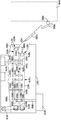
이제, 도 18을 참조하면, 예시적인 세척 시스템(1801)이 예시되어 있다. 몇몇 양태에서, 설명되는 바와 같은 세척 시스템(1801)은 버핑 시스템과 같은 임의의 다른 시스템과 완전히 별개이고 모듈형일 수 있다. 다른 양태에서, 세척 시스템(1801)은 버핑 시스템 등의 다른 시스템을 갖는 챔버에 대해 및/또는 챔버 내에 나란히 놓일 수 있다. 추가 양태에서, 세척 시스템(1801)은 발포재 물품으로부터 파티클 및/또는 다른 부스러기를 제거하는 환경을 제공하도록 이송 시스템에 연결될 수 있다. 몇몇 양태에서, 세척 시스템(1801)은 도 8에 도시된 바와 같은 버핑 구역(840) 등의 처리 구역에서 빠져나간 후에 제거 메카니즘(1880)을 이용하여 이송 메카니즘으로부터 제거된 발포재 물품(1830)을 받아들인다. 세척 시스템(1801)은 버핑 구역(840)과 같은 처리 구역과 완전히 별개일 수 있다. 세척 시스템(1801)은 제1 이송 메카니즘(1820), 제2 이송 메카니즘(1821), 하나 이상의 워시 제트(wash jet; 1842, 1844, 1846, 1848)를 각각 갖는 하나 이상의 워시 노즐 조립체(1840), 하나 이상의 분사 노즐 출구(1851, 1852)를 각각 갖는 하나 이상의 분사 노즐 조립체(1850), 하나 이상의 송풍기 출구(1861, 1862, 1863, 1864)를 각각 갖는 하나 이상의 송풍기(1860), 및/또는 드립 팬(drip pan; 1890)을 가질 수 있다. 몇몇 양태에서, 세척 시스템(1801)은 단 하나의 이송 메카니즘을 갖는다. 다른 양태에서, 세척 시스템(1801)은 2개보다 많은 이송 메카니즘을 갖는다. 제1 이송 메카니즘(1820)과 제2 이송 메카니즘(1821) 각각은, 예컨대 컨베이어 벨트일 수 있다. 몇몇 양태에서, 컨베이어 벨트는 발포재 물품을 컨베이어 벨트 상에 여전히 유지하면서 발포재 물품에 유체가 도달하게 하도록 구성될 수 있다. 예컨대, 컨베이어 벨트는 워시 노즐 조립체, 분사 노즐 조립체, 및 송풍기로부터의 유체가 발포재 물품의 표면의 적어도 일부 및/또는 대부분과 접촉하게 하기에 충분한 개구를 가질 수 있다. 컨베이어 벨트는 또한 발포재 물품이 투사된 유체, 가스, 및/또는 공기의 힘을 받는 동안에 발포재 물품을 제자리에 유지하도록 발포재 물품의 상부면 및 하부면의 적어도 일부와 충분히 맞물리기에 충분한 재료를 가질 수 있다. 몇몇 양태에서, 컨베이어 벨트는 일반용 벨트, 메시 벨트(mesh belt), 또는 적절한 개구를 갖는 광폭 체인형 벨트일 수 있다. Referring now to FIG. 18, an
제1 이송 메카니즘(1820)은 적어도 2개의 롤러, 즉 제1 롤러(1870)와 제2 롤러(1871)를 가질 수 있고, 구동 트레인(1816)에 연결될 수 있다. 구동 트레인(1816)은 제1 이송 메카니즘(1820)의 일부를 작동 및/또는 회전시키는 데에 사용될 수 있다. 제1 이송 메카니즘(1820)은 컨베이어 벨트(1874)를 가질 수 있다. 제1 컨베이어 벨트(1874)는 복귀부(1875)와 재료 접촉부(1876)를 가질 수 있다. 복귀부(1875)는 제1 롤러(1870)의 제1 측과 제2 롤러(1871)의 제1 측 상에 배치될 수 있는 제1 컨베이어 벨트(1874) 부분일 수 있다. 복귀부(1875)는 또한 발포재 물품(1830) 등의 발포재 물품과 접촉하지 않는 제1 컨베이어 벨트(1874) 부분일 수 있다. 또한, 복귀부(1875)는 제2 이송 메카니즘(1821)의 반대쪽에 있는 제1 컨베이어 벨트(1874) 부분일 수 있다. 재료 접촉부(1876)는 제1 롤러(1870)의 제2 측과 제2 롤러(1871)의 제2 측 상에 배치되는 컨베이어 벨트(1874) 부분일 수 있다. 재료 접촉부(1876)는 또한 발포재 물품(1830) 등의 발포재 물품과 접촉하는 제1 컨베이어 벨트(1874) 부분일 수 있다. 게다가, 재료 접촉부(1876)는 또한 제2 이송 메카니즘(1821)을 향해 면하는 제1 컨베이어 벨트(1874) 부분일 수 있다. The
제2 이송 메카니즘(1821)은 적어도 2개의 롤러, 즉 제1 롤러(1872)와 제2 롤러(1873)를 가질 수 있고, 구동 트레인(1816)에 연결될 수 있다. 구동 트레인(1816)은 제2 이송 메카니즘(1821)의 일부를 작동 및/또는 회전시키는 데에 사용될 수 있다. 제2 이송 메카니즘(1820)은 제2 컨베이어 벨트(1877)를 가질 수 있다. 제2 컨베이어 벨트(1877)는 복귀부(1879)와 재료 접촉부(1878)를 가질 수 있다. 복귀부(1879)는 제1 롤러(1872)의 제1 측과 제2 롤러(1873)의 제1 측 상에 배치될 수 있는 제2 컨베이어 벨트(1877) 부분일 수 있다. 복귀부(1879)는 또한 발포재 물품(1830) 등의 발포재 물품과 접촉하지 않는 제2 컨베이어 벨트(1877) 부분일 수 있다. 또한, 복귀부(1879)는 제1 이송 메카니즘(1820)의 반대쪽에 있는 제2 컨베이어 벨트(1877) 부분일 수 있다. 재료 접촉부(1878)는 제1 롤러(1872)의 제2 측과 제2 롤러(1873)의 제2 측 상에 배치되는 제2 컨베이어 벨트(1877) 부분일 수 있다. 재료 접촉부(1878)는 또한 발포재 물품(1830) 등의 발포재 물품과 접촉하는 제2 컨베이어 벨트(1877) 부분일 수 있다. 게다가, 재료 접촉부(1878)는 또한 제1 이송 메카니즘(1820)을 향해 면하는 제2 컨베이어 벨트(1877) 부분일 수 있다. 제1 컨베이어 벨트(1874)와 제2 컨베이어 벨트(1877)가 회전할 때에, 각 벨트의 섹션들은 번갈아 복귀부(1875), 재료 접촉부(1876), 재료 접촉부(1878), 및 복귀부(1879)에 관련될 수 있다. 예컨대, 제1 컨베이어 벨트(1874)가 회전할 때에, 복귀부(1875)의 섹션이 회전하고, 이에 따라 재료 접촉부(1876)의 섹션이 될 수 있다. 유사하게, 재료 접촉부(1876)의 섹션이 회전하고 복귀부(1875)의 섹션이 될 수 있다. The
제1 이송 메카니즘(1820)은, 발포재 물품(1830)이 제1 이송 메카니즘(1820)과 제2 이송 메카니즘(1821) 사이를 통과하게 하도록 제2 이송 메카니즘(1821) 아래에 위치 설정될 수 있다. 제1 이송 메카니즘(1820)과 제2 이송 메카니즘(1821)은 발포재 물품(1830)이 제1 이송 메카니즘(1820)과 제2 이송 메카니즘(1821) 사이에서 인장 가능하게 압축되도록 서로를 향해 인장될 수 있다. 몇몇 양태에서, 발포재 물품(1830)은, 발포재 물품(1830)의 상부면이 제2 이송 메카니즘(1821)과 접촉하고 및/또는 제2 이송 메카니즘에 의해 압축되도록 그리고 발포재 물품(1830)의 저부면이 제1 이송 메카니즘(1820)과 접촉하고 및/또는 제1 이송 메카니즘에 의해 압축되도록, 인장 가능하게 압축될 수 있다. 특히, 몇몇 양태에서, 발포재 물품(1830)의 저부면(또는 상부면)은 제2 컨베이어 벨트(1877)의 재료 접촉부(1878)와 접촉할 수 있고, 발포재 물품(1830)의 상부면(또는 저부면)은 제1 컨베이어 벨트(1874)의 재료 접촉부(1876)와 접촉할 수 있다. 몇몇 양태에서, 스프링 등의 인장 메카니즘(도시 생략)은 제1 이송 메카니즘(1820)과 제2 이송 메카니즘(1821)을 서로를 향해 스프링 로딩(spring loading)되게 하는 데에 사용될 수 있다. 몇몇 양태에서, 발포재 물품(1830)은, 제1 이송 메카니즘(1820)이 제2 이송 메카니즘(1821)을 향해 인장되는 일 없이, 또는 그 반대로 되는 일 없이, 제1 이송 메카니즘(1820)과 제2 이송 메카니즘(1821) 사이에 위치 설정될 수 있다. 특정한 양태에서, 제1 이송 메카니즘(1820)은 제2 이송 메카니즘(1821)으로부터 거리(1832)를 둘 수 있다. 특히, 거리(1832)는 제1 컨베이어 벨트(1874)의 재료 접촉부(1876)의 표면과 제2 컨베이어 벨트(1877)의 재료 접촉부(1878)의 표면 사이의 거리를 나타낼 수 있다. 발포재 물품(1830)은 높이(1831)를 가질 수 있다. 몇몇 양태에서, 거리(1832)는 높이(1831)와 동일할 수 있다. 다른 양태에서, 제1 이송 메카니즘(1820)은 거리(1832)가 변경될 수 있도록 제2 이송 메카니즘(1821)에 인장 가능하게 커플링(coupling)될 수 있다. 예컨대, 몇몇 양태에서, 발포재 물품(1830)이 제1 이송 메카니즘(1820) 및/또는 제2 이송 메카니즘(1821)과 접촉하기 전에, 거리(1832)는 높이(1831)보다 약간 작을 수 있다. 발포재 물품(1830)이 제1 이송 메카니즘(1820) 및/또는 제2 이송 메카니즘(1821)과 접촉할 때에, 거리(1832)는 높이(1831)와 동일하거나 더 클 수 있다.
추가 양태에서, 제1 이송 메카니즘(1820)은, 발포재 물품(1830)이 제2 이송 메카니즘(1821)에 도달하기 전에 제1 이송 메카니즘(1820)에 도달하도록 제2 이송 메카니즘(1821)로부터 거리(1896)만큼 오프셋될 수 있다. 제1 이송 메카니즘(1820)과 제2 이송 메카니즘(1821) 사이에 오프셋을 제공하면, 발포재 물품(1830)이 세척 시스템(1801)에 부드럽게 진입하게 될 수 있다. 예컨대, 발포재 물품(1830)은 제1 이송 메카니즘(1820)과 초기에 접촉하고 제1 이송 메카니즘(1820)의 상부에 유지될 수 있다. 발포재 물품(1830)이 이송 메카니즘(1820)의 상부에서 안정화되고 및/또는 제1 유지되면, 발포재 물품(1830)은 이어서 제2 이송 메카니즘(1821)에 의해 접촉될 수 있다. 발포재 물품(1830)이 제1 이송 메카니즘(1830) 상에서 이미 안정적이기 때문에, 제2 이송 메카니즘(1821)에 의한 접촉에 의해 발포재 물품(1830)이 제1 이송 메카니즘(1820)에서 벗어나지 않게 될 수 있다. 오히려, 제2 이송 메카니즘(1821)에 의한 접촉은 발포재 물품(1830)이 제1 이송 메카니즘(1820)과 제2 이송 메카니즘(1821) 사이에서 샌드위치(sandwich)되게 한다. 거리(1896)는 발포재 물품(1830)의 길이와 동일하거나 그보다 클 수 있다. 몇몇 양태에서, 거리(1896)는 발포재 물품(1830)의 길이의 2배, 3배, 4배 또는 5배와 동일하다. 다른 양태에서, 거리(1896)는 발포재 물품(1830)의 길이보다 작다.The
워시 노즐 조립체(1840)는 하나 이상의 펌프 모터(1814)에 연결되고 물 등의 유체를 발포재 물품(1830)을 향해 투사하여 발포재 물품(1830)으로부터 파티클을 제거하는 데 사용될 수 있다. 펌프 모터(1814)는 워시 노즐 조립체(1840)를 통해 유체를 펌핑하는 데 사용될 수 있다. 본 명세서에 사용되는 바와 같이, 유체는 액체, 공기 또는 가스일 수 있다. 각 워시 노즐 조립체(1840)는 서로 멀어지게 외측을 향해 연장되는 워시 제트(1842, 1844, 1846, 1848) 등의 하나 이상의 워시 제트를 가질 수 있다. 몇몇 양태에서, 제1 워시 노즐 조립체는 제2 워시 노즐 조립체보다 많거나 적은 워시 제트를 가질 수 있다. 다른 양태에서, 제1 워시 노즐 조립체는 제2 워시 노즐 조립체와 동일한 개수의 워시 제트를 가질 수 있다. 유체는 각각의 워시 제트에 의해 특정한 속도, 압력, 체적, 각도, 및 온도로 발포재 물품(1830)을 향해 투사될 수 있다. 워시 제트(1842, 1844)는 제2 이송 메카니즘(1821) 근처에 위치 설정될 수 있고, 워시 제트(1846, 1848)는 제1 이송 메카니즘(1820) 근처에 위치 설정될 수 있다. 몇몇 양태에서, 제1 세트의 워시 제트는 제1 이송 메카니즘 근처에 및/또는 발포재 물품의 제1 측 상에 위치 설정될 수 있고, 제2 세트의 워시 제트는 제2 이송 메카니즘 근처에 및/또는 발포재 물품의 제2 측 상에 위치 설정될 수 있다. 몇몇 양태에서, 워시 제트는 도 18에 도시된 바와 같이 제1 이송 메카니즘(1820) 및/또는 제2 이송 메카니즘(1821)의 각 루프(loop) 사이에 삽입될 수 있다. 워시 제트는 각 워시 제트가 제1 이송 메카니즘(1820) 및/또는 제2 이송 메카니즘(1821)의 루프의 절반만을 통과하도록 삽입될 수 있다. 이송 메카니즘의 각 루프 사이에 워시 제트를 위치 설정함으로써, 각 워시 제트는, 복귀부(1875) 및 재료 접촉부(1876)와 같이 컨베이어 벨트의 2개의 부분을 통하는 대신에, 재료 접촉부(1876)와 같이 컨베이어 벨트의 오직 1개 부분만을 통해 유체를 투사할 수 있다. 워시 제트가 유체를 컨베이어 벨트의 오직 1개 부분만을 통해 투사하게 함으로써, 발포재 물품과 더 양호한 유체 접촉이 형성된다. 워시 제트는 발포재 물품의 상부면 및/또는 저부면 상에서 컨베이어 벨트의 일부를 통해 유체를 투사하도록 위치 설정될 수 있다. 게다가, 워시 제트는 또한 발포재 물품의 측면 상에 유체를 투사하도록 컨베이어 벨트의 외측에 위치 설정될 수 있다. 컨베이어 벨트의 외측에 및/또는 컨베이어 벨트 사이에 위치 설정된 워시 제트는, 발포재 물품의 다양한 표면 상에 유체를 투사하도록 다양한 각도로 회전될 수 있다. Wash
분사 노즐 조립체(1850)는 물 등의 유체를 발포재 물품(1830)을 향해 투사할 수 있는 분사 노즐 출구(1851, 1852)와 같은 하나 이상의 분사 노즐 출구를 가질 수 있다. 분사 노즐 조립체(1850)는 특정한 속도, 압력, 체적, 각도 및 온도로 발포재 물품(1830)을 향해 유체를 투사할 수 있다. 몇몇 양태에서, 분사 노즐 출구(1852) 등의 각 분사 노즐 출구로부터 투사되는 유체의 특정한 속도, 압력, 체적, 각도, 온도 및 유형은 워시 제트(1842) 등의 각 워시 제트로부터 투사되는 유체의 특정한 속도, 압력, 체적, 각도, 온도, 및 유형과 상이할 수 있다. 다른 양태에서, 분사 노즐 출구(1852) 등의 각 분사 노즐 출구로부터 투사되는 유체의 특정한 속도, 압력, 체적, 각도, 온도 및 유형은 워시 제트(1842) 등의 각 워시 제트로부터 투사되는 유체의 특정한 속도, 압력, 체적, 각도, 온도, 및 유형과 동일할 수 있다. 제1 워시 노즐 조립체는 제2 워시 노즐 조립체로부터 거리(1898)를 두고 위치 설정될 수 있다. 게다가, 워시 노즐 조립체는 분사 노즐로부터 거리(1897)를 두고 위치 설정될 수 있다. 몇몇 양태에서, 거리(1898)는 거리(1897)와 동일하다. 다른 양태에서, 거리(1898)는 거리(1897)보다 크거나 작다. The
송풍기(1860)는 하나 이상의 송풍 모터(1812)에 연결될 수 있고, 가스 또는 공기가 발포재 물품(1830)을 향해 송풍되게 하는 송풍 출구(1861, 1862, 1863, 1864)를 가질 수 있다. 송풍 모터(1812)는 송풍기(1860)를 통해 가스 또는 공기를 제공하는 데 사용될 수 있다. 송풍기(1860)에 의해 제공되는 가스 또는 공기는 특정한 온도, 압력, 속도 및 체적을 가질 수 있다. 송풍기(1860)는 분사 노즐 조립체(1850) 등의 분사 노즐로부터 거리(1893)를 두고 위치 설정될 수 있다. 게다가, 송풍기(1860)는 워시 노즐 조립체(1840) 등의 워시 노즐로부터 거리(1892)를 두고 위치 설정될 수 있다. 몇몇 양태에서, 거리(1893)는 거리(1892)보다 크거나 동일하다. 다른 양태에서, 거리(1893)는 거리(1982)보다 작다. 드레인 팬(1890)이 발포재 물품(1830)으로부터 제거된 파티클 및 발포재 물품을 향해 투사된 유체를 포획 및/또는 포집할 수 있다.
몇몇 양태에서, 발포재 물품(1830)은 제거 메카니즘(1880)에 의해 이송 메카니즘으로부터 제거될 수 있고 세척 시스템(1801)에 진입할 수 있다. 세척 시스템(1801)에 진입할 때에, 발포재 물품(1830)은 제1 이송 메카니즘(1820) 및 제2 이송 메카니즘(1821)과 접촉할 수 있다. 몇몇 양태에서, 발포재 물품(1830)은 제2 이송 메카니즘(1821)과 접촉하기 전에 제1 이송 메카니즘(1820)과 접촉한다. 다른 양태에서, 발포재 물품(1830)은 제1 이송 메카니즘(1820) 및 제2 이송 메카니즘(1821)과 동시에 접촉한다. 추가 양태에서, 발포재 물품(1830)은, 유체가 발포재 물품(1830)을 향해 투사될 때에 발포재 물품(1830)을 제1 이송 메카니즘(1820)과 제2 이송 메카니즘(1821) 사이에 유지하도록 제1 이송 메카니즘(1820)과 제2 이송 메카니즘(1821) 사이에서 압축된다. 유체는 하나 이상의 워시 노즐 조립체(1840), 및 하나 이상의 분사 노즐 조립체(1850)에 의해 발포재 물품(1830)을 향해 투사될 수 있다. 게다가, 몇몇 양태에서, 가스 또는 공기는 송풍기(1860)에 의해 발포재 물품(1830)을 향해 투사될 수 있다. 발포재 물품(1830)을 향해 투사된 유체는 드레인 팬(1890)에 의해 포획 및/또는 포집될 수 있다. 드레인 팬(1890)은, 파티클 및/또는 유체가 세척 시스템(1801)으로부터 드레인(drain)될 수 있도록 다양한 방향으로 각도를 이룰 수 있도록 하나 이상의 섹션을 가질 수 있다. In some embodiments, the foamed
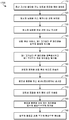
이제, 도 13을 참조하면, 본 발명에 따라 발포재 물품을 프로세싱하는 방법(1300)이 예시되어 있다. 단계(1310)에서, 신발류 밑창의 일부일 수 있는 발포재 물품이 중간 크기 및 중간 형상을 갖도록 형성될 수 있다. 단계(1310)는, 예컨대 EVA 재료 내에서 발포제를 활성화시키도록 열 및/또는 압력을 이용하는 것과, 선택적으로, 팽창된 EVA 발포재 물품을 안정화시키는 것을 포함할 수 있다. 단계(1320)에서, 발포재 물품의 적어도 일부가 제거될 때까지, 미립자 이탄산나트륨 등의 파티클이 발포재 물품에 투사될 수 있다. 단계(1320)는 특정한 속도, 각도, 힘, 거리, 기간 등으로 파티클을 발포재 물품에 투사하는 복수 개의 별개의 분배기를 이용할 수 있다. 대안으로, 단계(1320)는 발포재 물품의 표면과 접촉하고 맞물리도록, 예컨대 챔버 내에서 대체로 순환하는 파티클을 이용할 수 있다. 게다가, 발포재 물품에 투사되는 파티클은 1.0 내지 5.0 모스의 경도를 가질 수 있다. 단계(1330)에서, 발포재 물품은 가열되고 최종 형상 및 최종 크기로 몰딩될 수 있다. 단계(1330)는 최종 발포재 물품의 원하는 최종 텍스쳐(texture), 형태, 구성, 및 기능적/심미적 특징을 부여할 수 있다. Turning now to FIG. 13, a
이제, 도 14를 참조하면, 본 발명에 따라 발포재 물품을 버핑하는 방법(1400)이 예시되어 있다. 단계(1410)에서, 중간 크기와 중간 형상을 갖는 발포재 물품이 형성될 수 있다. 단계(1410)는, 예컨대 EVA 재료 내에서 발포제를 활성화시키도록 열 및/또는 압력을 이용하는 것과, 선택적으로, 팽창된 EVA 발포재 물품을 안정화시키는 것을 포함할 수 있다. 발포재 물품을 중간 크기 및 중간 형상으로 형성할 때에, 발포재 물품은 제1 밀도를 갖는 제1 부분과 제2 밀도를 갖는 스킨층을 구비할 수 있다. 제2 밀도는 제1 밀도보다 클 수 있다. 단계(1420)에서, 미립자 이탄산나트륨 등의 파티클은, 스킨층의 적어도 일부가 발포재 물품으로부터 제거될 때까지 발포재 물품에 투사될 수 있다. 단계(1420)는 특정한 속도, 각도, 힘, 거리, 기간 등으로 발포재 물품에 파티클을 투사하는 복수 개의 별개의 분배기를 이용할 수 있다. 대안으로, 단계(1420)는 발포재 물품의 표면과 접촉하고 맞물리도록, 예컨대 챔버 내에서 대체로 순환하는 파티클을 이용할 수 있다. 게다가, 발포재 물품에 투사되는 파티클은 140 메시보다 큰 파티클 크기를 가질 수 있다. 단계(1430)에서는, 단계(1420)에서 버핑된 발포재 물품이 가열되고 최종 형상 및 최종 크기로 몰딩될 수 있다. 단계(1430)는 최종 발포재 물품의 원하는 최종 텍스쳐, 형태, 구성, 및 기능적/심미적 특징을 부여할 수 있다. Referring now to FIG. 14, a
이제, 도 15를 참조하면, 본 발명에 따라 발포재 물품을 버핑하는 방법(1500)이 예시되어 있다. 단계(1510)에서, 궁극적으로 신발류 밑창의 일부로 형성될 수 있는 프리폼 발포재 물품이 중간 크기와 중간 형상을 갖도록 형성될 수 있다. 단계(1510)는, 예컨대 EVA 재료 내에서 발포제를 활성화시키도록 열 및/또는 압력을 이용하는 것과, 선택적으로, 팽창된 EVA 발포재 물품을 안정화시키는 것을 포함할 수 있다. 단계(1520)에서, 미립자 이탄산나트륨 등의 파티클은, 발포재 물품의 적어도 일부가 제거될 때까지 발포재 물품에 투사될 수 있다. 단계(1520)는 특정한 속도, 각도, 힘, 거리, 기간 등으로 프리폼 발포재 물품에 파티클을 투사하는 복수 개의 별개의 분배기를 이용할 수 있다. 대안으로, 단계(1520)는 발포재 물품의 표면과 접촉하고 맞물리도록, 예컨대 챔버 내에서 대체로 순환하는 파티클을 이용할 수 있다. 게다가, 발포재 물품에 투사되는 파티클은 1.0 내지 5.0 모스의 경도와 140 메시보다 큰 파티클 크기를 가질 수 있다. 단계(1530)에서, 프리폼 발포재 물품은 가열되고 최종 형상 및 최종 크기로 몰딩될 수 있다. 단계(1530)는 최종 발포재 물품의 원하는 최종 텍스쳐, 형태, 구성, 및 기능적/심미적 특징을 부여할 수 있다. Turning now to FIG. 15, a
이제, 도 16을 참조하면, 본 발명에 따라 발포재 물품을 버핑하는 다른 방법(1600)이 예시되어 있다. 단계(1610)에서, 팽창된 EVA 발포재 물품 등의 발포재 물품이 중간 크기와 형상을 갖도록 예비 형성될 수 있다. 단계(1610)는, 예컨대 발포제를 활성화시키도록 열 및/또는 압력을 이용하는 것과, 그 후에 선택적으로 결과적인 팽창된 EVA 발포재 물품을 중간 크기 및 형상으로 안정화시키는 것을 포함할 수 있다. 단계(1610)는 발포재 물품의 표면 상에 스킨층을 형성할 수 있다. 단계(1620)에서, 발포재 물품은 챔버를 통해 이송될 수 있다. 단계(1620)는 체인 구동 장치 또는 컨베이어 벨트 등의 이송 메카니즘을 이용할 수 있고, 입구를 이용하여 챔버에 엑세스하게 할 수 있다. 단계(1630)에서, 발포재 물품이 챔버를 통해 이송되는 동안에 미립자 이탄산나트륨 등의 파티클이 발포재 물품에 투사될 수 있다. 단계(1630)는, 파티클이 발포재 물품과 접촉하는 속도, 힘, 충돌 각도 등을 필요로 하는 원하는 버핑 파라미터를 충족시킬 수 있다. 예컨대, 단계(1630)는 선택된 속도로, 선택된 힘으로, 그리고 발포재 물품과 선택된 각도로 접촉하도록, 특정한 크기를 갖는 이탄산나트륨 파티클을 투사할 수 있다. 단계(1630)는 파티클을 기지의 속도, 힘, 각도 등으로 투사하도록 압축 공기 또는 송풍기 등의 메카니즘을 이용하는 하나 이상의 분배기를 이용할 수 있다. Referring now to FIG. 16, another
단계(1630) 후에, 선택적인 단계(1635)가 예시적인 양태에서 수행될 수 있다. 그러나, 대안적인 예시적인 양태에서 선택적인 단계(1635)를 완전히 생략하는 것을 고려할 수 있다. 단계(1635)는 프로세스에서 재사용하도록 파티클의 회수를 제공한다. 예컨대, 크기 문턱값(예컨대, 140 메시)을 초과하는 파티클은 다음의 버핑 용례를 위해 프로세스에서 재활용될 수 있다. 문턱값 미만의 파티클은 포집되지만, 예시적인 양태에서 본 발명의 양태를 달성하는 데에 덜 효과적이기 때문에 시스템으로부터 제거될 수 있다. After
단계(1630) 또는 선택적인 단계(1635) 후에, 단계(1640)는, 세척에 의해, 버핑된 발포재 물품으로부터 여분의 파티클을 제거한다. 단계(1640)는 또한 상기 방법(1600)에서 선택적일 수 있다는 것이 예상된다. 단계(1640)는 공기 송풍기, 브러시, 진동 시스템 등과 같은 임의의 메카니즘 또는 프로세스를 이용할 수 있다. 단계(1650)에서, 버핑된 발포재 물품은, 예컨대 이송 메카니즘을 매개로 출구를 통해 챔버를 빠져나옴으로써, 챔버 밖으로 이송될 수 있다. 상기 방법(1600)은 버핑된 발포재 물품을 가열 및 몰딩을 통해 원하는 최종 형태로 형성하는 단계(1660)에서 종결될 수 있다. After
단계(1630)에서 미립자 이탄산나트륨 등의 파티클의 투사 파라미터는 적어도 부분적으로 단계(1610)에서 물품 상에 형성되는 스킨층의 두께, 경도, 또는 다른 특성 및/또는 단계(1660)에서 최종 발포재 물품을 형성하기 위해 요구되는 성형성 정도에 따라 선택될 수 있다. 예컨대, 단계(1660)에서 고도의 성형성이 요망되면 및/또는 단계(1610)에서 발포재 물품 상에 특히 두꺼운 스킨층이 형성될 것으로 예상되면, 단계(1630)는 단계(1610)에서 발포재 물품 상에 형성된 스킨층의 더 많은 양, 심지어는 전부를 제거하여 단계(1660)에서 원하는 만큼의 성형성을 보장하도록 파티클의 비교적 빠른 투사 속도, 특히 높은 투사력, 비교적 긴 투사 기간 등을 포함할 수 있다. 다른 한편으로, 본 발명에 따른 시스템 및 방법의 다른 용례는 발포재 물품의 외측으로부터 스킨층을 적게 제거할 것을 요구할 수 있고, 이에 따라 단계(1630)의 파티클 투사 파라미터가 조정되게 될 수 있다. The projection parameters of the particles, such as particulates, such as sodium carbonate, in
이제, 도 17을 참조하면, 발포재 물품을 버핑하기 위한, 본 발명에 따른 다른 예시적인 방법(1700)이 예시되어 있다. 단계(1710)에서, 중간 크기와 형상을 갖는 발포재 물품이 예비 형성된다. 단계(1710)는 열과 압력을 이용하여 EVA 재료 내에서 발포제를 활성화시키고 EVA 발포재 물품을 형성하는 것을 포함할 수 있지만, 다른 유형의 발포재 물품이 본 발명에 따라 단계(1710)에서 예비 형성될 수 있다. 단계(1710)는 발포재 물품을 최종 크기 및 최종 형상으로 형성하는 것을 방해할 수 있는 스킨층이 발포재 물품 상에 형성되게 할 수 있다. 단계(1720)에서, 발포재 물품은 이송 메카니즘 상에 유지될 수 있다. 단계(1720)는 전술한 예시적인 유지 메카니즘 등의 유지 메카니즘을 이용할 수 있다. 단계(1730)에서, 발포재 물품은 버핑 챔버 내로 이송될 수 있다. 적절한 버핑 챔버의 몇몇 예가 위에 설명되어 있다. 별개의 버핑 챔버와 세척 챔버가 설명되어 있지만, 본 명세서에서 고려된 바와 같이, 공통의 챔버가 버핑 메카니즘과 세척 메카니즘을 모두 수용할 수 있다. 단계(1730)는 발포재 물품이 단계(1720)에서 유지되는 이송 메카니즘을 이용할 수 있다. Referring now to FIG. 17, another
단계(1740)에서, 제1 크기보다 크고 제2 크기보다 작은 이탄산나트륨 등의 파티클이 버핑 챔버 내에서 발포재 물품에 투사될 수 있다. 몇몇 양태에서, 제1 크기는 140 메시일 수 있고 제2 크기는 20 메시일 수 있다. 그러나, 파티클의 선택에 적용되는 유일한 제약은, 제1 크기, 즉 버핑에 사용하기 위한 파티클의 최소 허용 크기인 것을 고려할 수 있다. 단계(1740)는 다수의 분배기를 이용할 수 있고 파티클을 원하는 버핑 파라미터로, 예컨대 원하는 각도, 힘, 거리 등으로 투사할 수 있다. 단계(1740)는 버핑 챔버 내의 다수의 지점에서 반복될 수 있다. 단계(170)의 각각의 반복은 상이한 크기의 파티클 및/또는 상이한 버핑 파라미터를 이용할 수 있다. 단계(1750)에서, 제1 크기(예컨대, 140 메시)보다 큰 파티클이 추가 버핑 용례를 위해 재활용될 수 있고 제1 크기보다 작은 파티클은 폐기될 수 있다. 단계(1750)의 효과는, 몇몇 예에서 전술한 바와 같이, 효과적으로 버핑하기에는 파티클이 너무 작게 될 때가지 추가 발포재 물품을 버핑하도록 파티클을 재사용하는 것일 수 있다. 단계(1760)에서, 발포재 물품은 버핑 챔버 밖으로 이송될 수 있다. 단계(1760)는 발포재 물품이 단계(1720)에서 유지되었던 이송 메카니즘을 이용할 수 있다. 단계(1765)에서, 발포재 물품은 이송 메카니즘으로부터 제거될 수 있다. 단계(1765)는 제거 메카니즘에 의해, 수동으로, 또는 임의의 다른 수단을 통해 수행될 수 있다. At
단계(1770)에서, 발포재 물품은 세척 구역으로 이송될 수 있다. 단계(1770)는 발포재 물품이 단계(1720)에서 유지되었던 이송 메카니즘을 이용할 수 있다. 또한, 단계(1760)와 단계(1770)는, 예컨대 버핑 챔버와 세척 구역이 시스템 내에서 바로 인접해 있다면, 상기 방법(1700)의 단일 단계로 조합될 수 있다. 단계(1780)에서, 남아 있는 파티클의 일부 또는 전부가 세척 구역 내에서 발포재 물품으로부터 제거될 수 있다. 단계(1780)는 이탄산나트륨의 일부 또는 전부를 세척 구역 내에서 발포재 물품으로부터 제거하기 위해 이동 공기, 브러시, 물 또는 다른 용제, 진동 시스템, 또는 임의의 다른 수단을 이용할 수 있다. 상기 방법(1700)은 발포재 물품을 최종 크기 및 형상으로 형성하는 단계(1790)에서 종결될 수 있다. 단계(1790)는 최종 제품을 생산할 수 있거나, 또는 최종 제품의 후속 조립에 사용하기 위한 구성요소를 제공할 수 있다. In
도 19a는 본 발명의 양태에 따른, 중간 크기와 형상을 갖는 발포재 물품(1900)의 측면 사시도를 예시한다. 발포재 물품(1900)은 저부면(1904), 측벽(1907), 및 상부면을 갖는다. 측벽은 발포재 물품 둘레에서, 예컨대 예시적인 양태에서 발가락 단부(1910), 안쪽 측부, 바깥쪽 측부(1906), 및 뒤꿈치 단부(1908)를 따라 연장될 수 있다. 하나 이상의 특정한 부분 또는 일반적인 부분이 본 발명의 양태에 따라 버핑될 수 있다는 점이 예상된다. 예컨대, 측벽(1907)[또는 측벽(1907)의 부분]은 효과적으로 버핑되는 영역이고, 저부면(1904)[또는 저부면(1904)의 부분]은 실질적으로 버핑되지 않은 상태로 남아 있는 것을 고려할 수 있다. 또한, 위에서 암시한 바와 같이, 예시적인 양태에서, 안쪽 측부, 바깥쪽 측부(1906), 및 뒤꿈치 단부(1908) 등의 측벽(1907)의 부분은 버핑될 수 있는 반면, 발가락 단부(1910)는 실질적으로 버핑되지 않은 상태로 남아 있는 것을 고려할 수 있다. 버핑할 하나 이상의 부분의 선택은 발포재 물품에 리몰딩(remolding)이 일어나도록 의도되는 곳에 따라 좌우될 수 있다. 예컨대, 측벽(1907)이 이후의 몰딩 작업에 의해 크기 및/또는 형상의 변화를 받을 주요 부분이면, 버핑 작업은 이들 특별한 영역에 집중될 수 있다. 달리 말해서, 버핑 후 몰딩되는 특징부가 형성되도록 의도되는 지점이 발포재 물품의 어떤 부분이 버핑 작업에 의해 버핑되는지를 결정할 수 있다고 예상된다. 그러한 버핑 작업은 버핑 후 몰딩 프로세스를 억제할 수 있는 발포재 물품의 외부면의 부분을 제거한다. 19A illustrates a side perspective view of a
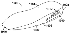
도 19b는 본 발명의 양태에 따라 최종 크기와 형상을 갖는 발포재 물품(1902)의 측면 사시도를 예시한다. 예시적인 양태에서, 발포재 물품(1902)은 도 19a의 발포재 물품(1900)의 리몰딩된 양태이다. 이 예에서, 발포재 물품(1900)의 크기와 형상은 버핑 프로세스 및 후속 몰딩 프로세스를 통해 조정된다. 후속 몰딩 프로세스는 특징부(1910, 1912) 등의 치수 특징부를 추가하는 것과 같이 발포재 물품의 크기와 형상을 개량하도록 실시될 수 있다. 특징부(1910, 1912)는 발포재 물품(1902)의 원하는 최종 크기 및/또는 형상을 달성하도록 버핑 후 몰딩 작업에 의해 형성될 수 있다. 특징부(1910, 1912)는 단순히 예시 목적을 위해 제공되고, 돌기, 함입부, 텍스쳐 등의 임의의 특징부가 버핑 후 몰딩 작업에서 형성될 수 있다는 것이 예상된다. 내측 부분보다 측벽(1907)의 표면에 근접한 더 조밀한 부분과 같은 발포재의 제거는, 버핑 작업에 의해 실질적으로 영향을 받는 이들 영역에서 버핑 후 몰딩 효과를 향상시킬 수 있다. 달리 말해서, 비교적 더 조밀한 재료의 부분이 버핑 프로세스에 의해 제거되기 때문에, 버핑 작업이 버핑 후 몰딩 작업의 효과를 증대시킨다고 예상된다. Figure 19B illustrates a side perspective view of a
본 발명에 따른 시스템 및 방법이 특정한 예와 관련하여 설명되었지만, 이들 예에 대해 이루어진 변형이 본 발명의 범위 내에 속한다는 것이 예상된다. 예컨대, 버핑을 위해 파티클을 물품에 제공하도록 임의의 개수 또는 배향의 분배 메카니즘이 사용될 수 있다. 사용된 파티클의 재활용은 임의의 제거되는 파티클을 물품 상의 스킨층으로부터 제거하도록, 또는 이와 달리 추가 사용을 위해 이탄산나트륨 등의 포집된 파티클의 연속적인 적합성을 평가하도록 사이클론 분리 등의 메카니즘과 기법을 수반할 수 있다. 버핑을 위한 다수의 구역이 채용될 수 있고, 상이한 구역은 상이한 버핑 파라미터 또는 심지어는 상이한 유형의 파티클을 채용할 수 있다. 본 명세서의 예에서 설명된 것을 벗어나서, 다양한 유형의 이송 메카니즘이 본 발명에 따라 사용될 수 있다. 본 발명에 따른 시스템의 구성요소의 다양한 예는 본 발명의 범위에서 벗어남이 없이 재구성되거나 생략될 수 있다. 유사하게, 본 발명에 따른 방법은 본 명세서에 예시된 것과 상이한 순서로 단계들에 의해 수행될 수 있고, 본 발명의 범위로부터 벗어남이 없이 다른 몇몇의 단계가 추가되거나 생략될 수 있다.While the systems and methods according to the present invention have been described in connection with specific examples, it is contemplated that modifications made to these examples are within the scope of the present invention. For example, any number or orientation of dispensing mechanism may be used to provide particles to the article for buffing. Recycling of the used particles entails mechanisms and techniques such as cyclone separation to remove any removed particles from the skin layer on the article, or alternatively to assess the subsequent suitability of the captured particles such as sodium carbonate for further use can do. A plurality of zones for buffing may be employed, and different zones may employ different buffing parameters or even different types of particles. Various types of transport mechanisms can be used in accordance with the present invention, beyond what is described in the examples herein. Various examples of the components of the system according to the present invention can be reconstructed or omitted without departing from the scope of the present invention. Similarly, the method according to the present invention may be performed by steps in a different order than that exemplified herein, and several other steps may be added or omitted without departing from the scope of the present invention.
Claims (22)
발포재 물품을 상기 버핑 시스템의 적어도 일부를 통해 이동시키는 이송 메카니즘;
발포재 물품을 이송 메카니즘에 고정시키는 적어도 하나의 유지 메카니즘;
적어도 입구 및 적어도 출구를 갖는 챔버로서, 상기 입구를 통해 이송 메카니즘은 발포재 물품을 챔버 내로 이동시키고, 상기 출구를 통해 이송 메카니즘은 발포재 물품을 챔버 밖으로 이동시키며, 챔버는, 이송 메카니즘이 발포재 물품을 챔버를 통해 이동시킬 때에 발포재 물품을 둘러싸는 상부, 저부, 및 측부를 적어도 포함하는 것인 챔버;
파티클(particle)을 챔버 내의 발포재 물품에 추진시키는 적어도 하나의 미립자 분배기
를 포함하고, 상기 파티클은 1.0 내지 5.0 모스(Mohs)의 경도와 140 메시(mesh)보다 큰 파티클 크기를 갖는 것인 발포재 물품의 버핑 시스템.A buffing system for foamed articles,
A transfer mechanism for moving the foam material through at least a portion of the buffing system;
At least one retention mechanism for securing the foam material to the transport mechanism;
Wherein the transfer mechanism through the inlet moves the foam material article into the chamber and the transfer mechanism through the outlet moves the foam material article out of the chamber, the chamber being configured such that the transfer mechanism moves the foam material < RTI ID = 0.0 > A chamber surrounding the foam article, the chamber comprising at least a top, a bottom, and a side surrounding the article when the article is moved through the chamber;
At least one particulate distributor for propelling particles to the foam material within the chamber,
Wherein the particles have a hardness of 1.0 to 5.0 Mohs and a particle size greater than 140 mesh.
상기 파티클을 적어도 하나의 미립자 분배기에 제공하도록 적어도 하나의 미립자 분배기에 연결되는 파티클 저장조
를 더 포함하는 발포재 물품의 버핑 시스템.The method according to claim 1,
A particle reservoir connected to at least one particulate distributor for providing said particles to at least one particulate distributor;
Further comprising the steps of:
상기 발포재 물품을 유지 메카니즘으로부터 맞물림 해제하도록 된 제거 메카니즘
을 더 포함하고, 상기 제거 메카니즘은 세척 구역의 대향 측부에 한쌍의 돌출부를 포함하며, 유지 메카니즘이 제거 메카니즘과 대향하는 방향으로 이송될 때에 발포재 물품과 맞물리고 발포재 물품을 지지하도록 된 것인 발포재 물품의 버핑 시스템.The method according to claim 1,
A removal mechanism adapted to disengage the foam material article from the retention mechanism
Wherein the removal mechanism comprises a pair of projections on opposite sides of the wash zone and is adapted to engage the foam article when the retention mechanism is transported in a direction opposite the removal mechanism and to support the foam article Buffing system of foamed goods.
상기 미립자 분배기가 파티클을 분배한 후에, 발포재 물품으로부터 파티클을 제거하는 세척 메카니즘
을 더 포함하는 발포재 물품의 버핑 시스템.The method according to claim 1,
A cleaning mechanism for removing particles from the foamed article after the particle dispenser dispenses the particles,
Further comprising the steps of:
상기 경사벽에 의해 포집된 파티클을 적어도 하나의 미립자 분배기로 운반하는 흡기 메카니즘
을 더 포함하는 발포재 물품의 버핑 시스템.12. The method of claim 11,
And an intake mechanism for conveying the particles collected by the inclined wall to at least one particulate distributor
Further comprising the steps of:
버핑 챔버를 둘러싸는 상부, 저부, 및 측부를 포함하는 버핑 챔버로서, 발포재 물품을 챔버 내로 받아들이는 적어도 하나의 입구와 발포재 물품이 버핑 챔버에서 빠져나가게 허용하는 출구를 더 포함하는 것인 버핑 챔버;
상기 버핑 챔버의 버핑 구역 내의 발포재 물품에 파티클을 분배하는, 버핑 챔버 내의 복수 개의 분배기로서, 상기 파티클은 140 메시보다 큰 파티클 크기를 갖는 것인 복수 개의 분배기;
버핑 챔버의 입구를 통해 버핑 챔버 내로, 버핑 챔버의 버핑 구역을 통해, 그리고 버핑 챔버의 출구를 통해 버핑 챔버 밖으로 상기 발포재 물품을 이동시키도록 구성된 이송 메카니즘
을 포함하는 발포재 물품의 버핑 시스템.A bucking system for foamed articles,
A buffing chamber comprising an upper portion, a bottom portion and a side portion surrounding the buffing chamber, the at least one inlet receiving the foamed material article into the chamber, and the outlet allowing the foamed material article to escape from the buffing chamber. chamber;
A plurality of dispensers in a buffing chamber for dispensing particles to a foam material within a buffing zone of the buffing chamber, the particles having a particle size greater than 140 meshes;
A transfer mechanism configured to move the foam material out of the buffing chamber through the buffing chamber of the buffing chamber and through the outlet of the buffing chamber through the inlet of the buffing chamber,
Wherein the baffling system comprises:
세척 메카니즘
을 더 포함하고, 상기 세척 메카니즘은 발포재 물품이 버핑 챔버에서 빠져나간 후에 발포재 물품으로부터 파티클을 제거하도록 된 것인 발포재 물품의 버핑 시스템.14. The method of claim 13,
Cleaning Mechanism
Wherein the cleaning mechanism is adapted to remove particles from the foamed article after the foamed article has exited the buffing chamber.
반복된 분배를 위해 상기 버핑 구역 아래의 경사벽으로부터 버핑 챔버 내의 복수 개의 분배기로 상기 파티클을 운반하는 재활용 메카니즘
을 더 포함하는 발포재 물품의 버핑 시스템.18. The method of claim 17,
A recycling mechanism for conveying the particles from the slope wall below the buffing zone to the plurality of distributors in the buffing chamber for repeated dispensing,
Further comprising the steps of:
상기 파티클의 서브세트(subset)가 140 메시보다 작은 파티클 크기를 가질 때에 시스템으로부터 파티클의 상기 서브세트를 제거하는, 재활용 메카니즘 내의 필터
를 더 포함하는 발포재 물품의 버핑 시스템.19. The method of claim 18,
A filter in a recycling mechanism that removes the subset of particles from the system when the subset of particles has a particle size of less than 140 meshes
Further comprising the steps of:
발포재 물품을 이송 메카니즘에 고정하도록 된 유지 메카니즘으로서, 유지 메카니즘은 발포재 물품을 이송 메카니즘에 착탈 가능하게 유지하기 위해 발포재 물품의 일부를 천공하는 적어도 하나의 프롱을 포함하는 것인 유지 메카니즘;
유지 메카니즘으로부터 발포재 물품을 맞물림 해제하도록 된 제거 메카니즘
을 더 포함하고, 상기 제거 메카니즘은 세척 구역의 출구의 대향 측부에 한쌍의 돌출부를 포함하며, 유지 메카니즘이 제거 메카니즘과 대향하는 방향으로 이송될 때에 발포재 물품과 맞물리고 발포재 물품을 지지하도록 된 것인 발포재 물품의 버핑 시스템.16. The method of claim 15,
A retention mechanism adapted to secure a foam material article to a transport mechanism, the retention mechanism comprising at least one prong that punctures a portion of the foam material article to detachably retain the foam material article in the transport mechanism;
Removal mechanism adapted to disengage the foam material from the retention mechanism
Wherein the removal mechanism includes a pair of protrusions on opposite sides of the outlet of the wash zone and wherein the retaining mechanism engages the foam material when it is transported in a direction opposite the removal mechanism, Of the foam material.
제1 챔버를 둘러싸는 상부, 저부, 및 측부를 포함하는 제1 챔버로서, 제1 챔버는 발포재 물품을 제1 챔버 내에 받아들이는 입구와 발포재 물품이 제1 챔버에서 빠져나가게 하는 출구를 적어도 더 포함하는 것인 제1 챔버;
상기 제1 챔버의 버핑 구역 내의 발포재 물품에 압축 유체 스트림 내의 파티클을 분배하는, 제1 챔버 내의 복수 개의 분배기로서, 파티클은 1.0 내지 5.0 모스의 경도를 갖는 것인 복수 개의 분배기;
제1 챔버의 입구를 통해 제1 챔버 내로, 제1 챔버의 버핑 구역을 통해, 제1 챔버의 출구를 통해 제1 챔버 밖으로, 그리고 제2 챔버의 입구를 통해 제2 챔버 내로 발포재 물품을 이동시키도록 구성된 이송 메카니즘
을 포함하는 발포재 물품의 버핑 시스템.A bucking system for foamed articles,
A first chamber comprising an upper portion, a bottom portion and a side portion surrounding the first chamber, the first chamber having an inlet for receiving the foamed article article in the first chamber and an outlet for withdrawing the foamed article article from the first chamber, Further comprising: a first chamber;
A plurality of dispensers in a first chamber for dispensing particles in a compressed fluid stream to a foamed material article in the first chamber's buffing zone, wherein the particles have a hardness of 1.0 to 5.0 mos;
Moving the foamed material through the inlet of the first chamber into the first chamber, through the buffing zone of the first chamber, out of the first chamber through the outlet of the first chamber, and into the second chamber through the inlet of the second chamber Lt; RTI ID = 0.0 >
Wherein the baffling system comprises:
상기 발포재 물품을 유지 메카니즘으로부터 맞물림 해제하도록 된 제거 메카니즘
을 더 포함하고, 상기 제거 메카니즘은 세척 구역의 출구의 대향 측부에 한쌍의 돌출부를 포함하며, 유지 메카니즘이 제거 메카니즘과 대향하는 방향으로 이송될 때에 발포재 물품과 맞물리고 발포재 물품을 지지하도록 된 것인 발포재 물품의 버핑 시스템.22. The method of claim 21,
A removal mechanism adapted to disengage the foam material article from the retention mechanism
Wherein the removal mechanism includes a pair of protrusions on opposite sides of the outlet of the wash zone and wherein the retaining mechanism engages the foam material when it is transported in a direction opposite the removal mechanism, Of the foam material.
Applications Claiming Priority (3)
| Application Number | Priority Date | Filing Date | Title |
|---|---|---|---|
| US14/060,224 US9789584B2 (en) | 2013-10-22 | 2013-10-22 | Buffing expanded foam items |
| US14/060,224 | 2013-10-22 | ||
| PCT/US2014/059904 WO2015061057A1 (en) | 2013-10-22 | 2014-10-09 | Buffing expanded foam items |
Publications (2)
| Publication Number | Publication Date |
|---|---|
| KR20160077108A true KR20160077108A (en) | 2016-07-01 |
| KR101823804B1 KR101823804B1 (en) | 2018-01-30 |
Family
ID=51752195
Family Applications (1)
| Application Number | Title | Priority Date | Filing Date |
|---|---|---|---|
| KR1020167013289A Active KR101823804B1 (en) | 2013-10-22 | 2014-10-09 | Buffing expanded foam items |
Country Status (7)
| Country | Link |
|---|---|
| US (1) | US9789584B2 (en) |
| EP (1) | EP3060079B1 (en) |
| KR (1) | KR101823804B1 (en) |
| CN (2) | CN104552021B (en) |
| MX (1) | MX2016005149A (en) |
| TW (1) | TWI632023B (en) |
| WO (1) | WO2015061057A1 (en) |
Families Citing this family (10)
| Publication number | Priority date | Publication date | Assignee | Title |
|---|---|---|---|---|
| US9789584B2 (en) * | 2013-10-22 | 2017-10-17 | Nike, Inc. | Buffing expanded foam items |
| US10556320B2 (en) * | 2017-01-07 | 2020-02-11 | James T. Carnathan | Computerized method and apparatus for automated sand blasting |
| TWI720315B (en) | 2017-05-15 | 2021-03-01 | 荷蘭商耐克創新有限合夥公司 | Apparatus, system and method for buffing a footwear part |
| CN109483334A (en) * | 2018-12-12 | 2019-03-19 | 深圳麦德利宇航材料科技有限公司 | A kind of efficient technique for grinding of aero seat foam |
| US12029282B2 (en) | 2019-09-16 | 2024-07-09 | Nike, Inc. | Buffing system for footwear |
| CN111070542B (en) * | 2019-12-23 | 2021-08-24 | 安徽鲲鹏装备模具制造有限公司 | Synchronous stop gear of preceding baffle based on auxiliary drive |
| US11787578B2 (en) | 2020-09-25 | 2023-10-17 | Express Scripts Strategic Development, Inc. | Cleaner assembly for an automated dispensing device |
| CN112548870B (en) * | 2020-11-10 | 2022-09-27 | 林元霞 | System for removing oxide layer on surface of steel based on Internet of things |
| CN113601333B (en) * | 2021-07-22 | 2022-05-27 | 深圳市九丞技术有限公司 | Intelligent flexible polishing method, device and equipment |
| DE102022103246A1 (en) * | 2022-02-11 | 2023-08-17 | Homag Gmbh | Method for cleaning a surface of a workpiece, a consumable and a component of a processing machine and processing machine |
Family Cites Families (29)
| Publication number | Priority date | Publication date | Assignee | Title |
|---|---|---|---|---|
| US3246352A (en) | 1963-03-07 | 1966-04-19 | Wellman Co | Sole cutting apparatus |
| US3716947A (en) * | 1971-01-21 | 1973-02-20 | Carborundum Co | Abrasive blast cleaning system |
| US3702519A (en) | 1971-07-12 | 1972-11-14 | Chemotronics International Inc | Method for the removal of unwanted portions of an article by spraying with high velocity dry ice particles |
| US3822617A (en) * | 1971-09-23 | 1974-07-09 | Weichel Ernst | Apparatus for continuous transfer of a material rope from a pile to a following device |
| DE2454866A1 (en) * | 1974-11-20 | 1976-05-26 | Berger Maschf Gmbh | SPIN BLASTING SYSTEM FOR CLEANING PROFILED WORKPIECES |
| US4740218A (en) * | 1986-06-12 | 1988-04-26 | James Hensley | Blast cleaning machine and conveyor therefor |
| US5123206A (en) | 1987-12-04 | 1992-06-23 | Whitemetal, Inc. | Wet abrasive blasting method |
| US5107629A (en) * | 1989-11-09 | 1992-04-28 | The Celotex Corporation | Texturing of acoustical mineral fiberboard with wheel blast machine |
| JPH03191902A (en) | 1989-12-21 | 1991-08-21 | Asahi Corp | Production method of intermediate bottom for shoes |
| US5203124A (en) * | 1991-05-03 | 1993-04-20 | Pangborn Corporation | Wire mesh conveyor abrasive machine and abrasive return system therefor |
| US5203665A (en) * | 1991-10-11 | 1993-04-20 | Lars Lande | Apparatus for removing compost from plastic bags |
| US5182882A (en) * | 1991-12-30 | 1993-02-02 | Fedco Automotive Components Co., Inc. | Heater cores having exposed surfaces burnished by wet blasting |
| CA2097222A1 (en) * | 1992-06-01 | 1993-12-02 | Somyong Visaisouk | Particle blasting utilizing crystalline ice |
| US5308404A (en) | 1993-01-21 | 1994-05-03 | Church & Dwight Co., Inc. | Less aggressive blast media formed from compacted particles |
| CA2103685C (en) * | 1993-08-06 | 1997-11-11 | Charles P. Elliott | Blast cleaning apparatus and method with laterally moving conveyor |
| US5485643A (en) * | 1994-08-01 | 1996-01-23 | Dexter Shoe Company | Apparatus and process for trimming a sole of a shoe |
| CA2180503C (en) * | 1996-07-04 | 1999-09-14 | Charles Perry Elliott | Rotatable blast cleaning conveying surface and apparatus |
| KR19980070998A (en) * | 1997-02-03 | 1998-10-26 | 히가시데츠로 | Polishing apparatus, polishing member and polishing method |
| IT1314570B1 (en) | 2000-02-18 | 2002-12-20 | Autec Di Geri Ing Fabrizio & C | EQUIPMENT FOR AUTOMATIC TRIMMING OF SOLES IN PLASTIC MATERIAL FOR FOOTWEAR AND RELATED TRIMMING METHOD |
| US6719612B2 (en) * | 2001-05-14 | 2004-04-13 | Universal Ice Blast, Inc. | Ice blast cleaning cabinet |
| US6442968B1 (en) * | 2001-10-30 | 2002-09-03 | Albert S. Elias | Apparatus for rapid, high volume production of solid CO2 pellets |
| EP1758711B1 (en) * | 2004-06-21 | 2013-08-07 | Ebara Corporation | Polishing apparatus and polishing method |
| US20120056346A1 (en) | 2009-05-22 | 2012-03-08 | Maurer Myron J | Improved method for extracting shaped foam articles from a forming mold cavity |
| US20110091688A1 (en) | 2009-10-16 | 2011-04-21 | Maurer Myron J | Process for producing a shaped foam article |
| WO2011149706A1 (en) | 2010-05-27 | 2011-12-01 | Dow Global Technologies Llc | Method of manufacturing a shaped foam article |
| WO2011163160A1 (en) | 2010-06-23 | 2011-12-29 | Dow Global Technologies Llc | Method for stamping a shaped foam article |
| US8764513B1 (en) * | 2011-01-05 | 2014-07-01 | Richard L. Spears | Media recycling apparatus and process for wet media blast operations |
| US9272391B2 (en) * | 2011-05-25 | 2016-03-01 | Nike, Inc. | Sodium bicarbonate puck cleaning and painting |
| US9789584B2 (en) * | 2013-10-22 | 2017-10-17 | Nike, Inc. | Buffing expanded foam items |
-
2013
- 2013-10-22 US US14/060,224 patent/US9789584B2/en active Active
-
2014
- 2014-10-09 KR KR1020167013289A patent/KR101823804B1/en active Active
- 2014-10-09 MX MX2016005149A patent/MX2016005149A/en unknown
- 2014-10-09 EP EP14786584.4A patent/EP3060079B1/en active Active
- 2014-10-09 WO PCT/US2014/059904 patent/WO2015061057A1/en not_active Ceased
- 2014-10-20 TW TW103136117A patent/TWI632023B/en active
- 2014-10-22 CN CN201410568010.5A patent/CN104552021B/en active Active
- 2014-10-22 CN CN201420615882.8U patent/CN204736105U/en not_active Expired - Fee Related
Also Published As
| Publication number | Publication date |
|---|---|
| MX2016005149A (en) | 2016-08-17 |
| EP3060079A1 (en) | 2016-08-31 |
| CN104552021A (en) | 2015-04-29 |
| EP3060079B1 (en) | 2019-04-10 |
| CN204736105U (en) | 2015-11-04 |
| TWI632023B (en) | 2018-08-11 |
| KR101823804B1 (en) | 2018-01-30 |
| CN104552021B (en) | 2019-03-08 |
| TW201515767A (en) | 2015-05-01 |
| WO2015061057A1 (en) | 2015-04-30 |
| US9789584B2 (en) | 2017-10-17 |
| US20150107030A1 (en) | 2015-04-23 |
Similar Documents
| Publication | Publication Date | Title |
|---|---|---|
| KR101823804B1 (en) | Buffing expanded foam items | |
| KR101836751B1 (en) | Buffing expanded foam items | |
| US20180065135A1 (en) | Spray applicating line and assembly for producing a coated part and including multiple overspray and recapture/recycle configurations | |
| CA2928448C (en) | Mat cleaning and drying apparatus and method | |
| CN103561910B (en) | Sodium bicarbonate puck cleaning and painting | |
| KR102115609B1 (en) | Dry and grind system for frozen pepper | |
| GB2069370A (en) | Internal coating of friction nuts | |
| EP3563940B1 (en) | Cup-washing device | |
| KR101794619B1 (en) | Machine for cotton be able to improving workability and smoothly supply | |
| CN109248877A (en) | Salted egg's cleaning machine | |
| JP2019005384A (en) | Container cleaning drip drying method and container cleaning drip drying machine | |
| US4959930A (en) | Washing machine | |
| NL2015322B1 (en) | Crate washing device and method. | |
| JP6998686B2 (en) | Moisture dripping and drying method and container processing equipment | |
| CN209222730U (en) | Salted egg's cleaning machine | |
| KR102063719B1 (en) | Sterilizing and drying apparatus for mat of vehicle floor | |
| JPH11138440A (en) | Blast washing device | |
| ES2665761T3 (en) | Particulate material treatment plant | |
| JP2004122090A (en) | Cleaning equipment | |
| JP2008109977A (en) | Floor wax stripping apparatus | |
| JPH0564537A (en) | Standing water wiper, attached substance releasing device and top plate cleansing machine | |
| JP2002355620A (en) | Peeling/washing apparatus for hanger with label and peeling/washing method using the same |
Legal Events
| Date | Code | Title | Description |
|---|---|---|---|
| A201 | Request for examination | ||
| PA0105 | International application |
Patent event date: 20160519 Patent event code: PA01051R01D Comment text: International Patent Application |
|
| PA0201 | Request for examination | ||
| PG1501 | Laying open of application | ||
| E902 | Notification of reason for refusal | ||
| PE0902 | Notice of grounds for rejection |
Comment text: Notification of reason for refusal Patent event date: 20170523 Patent event code: PE09021S01D |
|
| E701 | Decision to grant or registration of patent right | ||
| PE0701 | Decision of registration |
Patent event code: PE07011S01D Comment text: Decision to Grant Registration Patent event date: 20171130 |
|
| GRNT | Written decision to grant | ||
| PR0701 | Registration of establishment |
Comment text: Registration of Establishment Patent event date: 20180124 Patent event code: PR07011E01D |
|
| PR1002 | Payment of registration fee |
Payment date: 20180124 End annual number: 3 Start annual number: 1 |
|
| PG1601 | Publication of registration | ||
| FPAY | Annual fee payment |
Payment date: 20210108 Year of fee payment: 4 |
|
| PR1001 | Payment of annual fee |
Payment date: 20210108 Start annual number: 4 End annual number: 4 |
|
| FPAY | Annual fee payment |
Payment date: 20211215 Year of fee payment: 5 |
|
| PR1001 | Payment of annual fee |
Payment date: 20211215 Start annual number: 5 End annual number: 5 |
|
| PR1001 | Payment of annual fee |
Payment date: 20231218 Start annual number: 7 End annual number: 7 |
|
| PR1001 | Payment of annual fee |
Payment date: 20241216 Start annual number: 8 End annual number: 8 |