KR20160077183A - Portable surveillance system - Google Patents
Portable surveillance system Download PDFInfo
- Publication number
- KR20160077183A KR20160077183A KR1020167014181A KR20167014181A KR20160077183A KR 20160077183 A KR20160077183 A KR 20160077183A KR 1020167014181 A KR1020167014181 A KR 1020167014181A KR 20167014181 A KR20167014181 A KR 20167014181A KR 20160077183 A KR20160077183 A KR 20160077183A
- Authority
- KR
- South Korea
- Prior art keywords
- battery
- voltage
- capacitor bank
- power
- capacitor
- Prior art date
- Legal status (The legal status is an assumption and is not a legal conclusion. Google has not performed a legal analysis and makes no representation as to the accuracy of the status listed.)
- Ceased
Links
Images







Classifications
-
- H—ELECTRICITY
- H02—GENERATION; CONVERSION OR DISTRIBUTION OF ELECTRIC POWER
- H02J—ELECTRIC POWER NETWORKS; CIRCUIT ARRANGEMENTS OR SYSTEMS FOR SUPPLYING OR DISTRIBUTING ELECTRIC POWER; SYSTEMS FOR STORING ELECTRIC ENERGY
- H02J7/00—Circuit arrangements for charging or discharging batteries or for supplying loads from batteries
- H02J7/50—Circuit arrangements for charging or discharging batteries or for supplying loads from batteries acting upon multiple batteries simultaneously or sequentially
-
- H—ELECTRICITY
- H02—GENERATION; CONVERSION OR DISTRIBUTION OF ELECTRIC POWER
- H02J—ELECTRIC POWER NETWORKS; CIRCUIT ARRANGEMENTS OR SYSTEMS FOR SUPPLYING OR DISTRIBUTING ELECTRIC POWER; SYSTEMS FOR STORING ELECTRIC ENERGY
- H02J7/00—Circuit arrangements for charging or discharging batteries or for supplying loads from batteries
-
- H02J7/0013—
-
- H02J7/0021—
-
- H—ELECTRICITY
- H02—GENERATION; CONVERSION OR DISTRIBUTION OF ELECTRIC POWER
- H02J—ELECTRIC POWER NETWORKS; CIRCUIT ARRANGEMENTS OR SYSTEMS FOR SUPPLYING OR DISTRIBUTING ELECTRIC POWER; SYSTEMS FOR STORING ELECTRIC ENERGY
- H02J7/00—Circuit arrangements for charging or discharging batteries or for supplying loads from batteries
- H02J7/34—Parallel operation in networks using both storage and other DC sources, e.g. providing buffering
-
- H—ELECTRICITY
- H02—GENERATION; CONVERSION OR DISTRIBUTION OF ELECTRIC POWER
- H02J—ELECTRIC POWER NETWORKS; CIRCUIT ARRANGEMENTS OR SYSTEMS FOR SUPPLYING OR DISTRIBUTING ELECTRIC POWER; SYSTEMS FOR STORING ELECTRIC ENERGY
- H02J7/00—Circuit arrangements for charging or discharging batteries or for supplying loads from batteries
- H02J7/34—Parallel operation in networks using both storage and other DC sources, e.g. providing buffering
- H02J7/342—The other DC source being a battery actively interacting with the first one, i.e. battery to battery charging
-
- H—ELECTRICITY
- H02—GENERATION; CONVERSION OR DISTRIBUTION OF ELECTRIC POWER
- H02J—ELECTRIC POWER NETWORKS; CIRCUIT ARRANGEMENTS OR SYSTEMS FOR SUPPLYING OR DISTRIBUTING ELECTRIC POWER; SYSTEMS FOR STORING ELECTRIC ENERGY
- H02J7/00—Circuit arrangements for charging or discharging batteries or for supplying loads from batteries
- H02J7/34—Parallel operation in networks using both storage and other DC sources, e.g. providing buffering
- H02J7/345—Parallel operation in networks using both storage and other DC sources, e.g. providing buffering using capacitors as storage or buffering devices
-
- H—ELECTRICITY
- H02—GENERATION; CONVERSION OR DISTRIBUTION OF ELECTRIC POWER
- H02J—ELECTRIC POWER NETWORKS; CIRCUIT ARRANGEMENTS OR SYSTEMS FOR SUPPLYING OR DISTRIBUTING ELECTRIC POWER; SYSTEMS FOR STORING ELECTRIC ENERGY
- H02J7/00—Circuit arrangements for charging or discharging batteries or for supplying loads from batteries
- H02J7/80—Circuit arrangements for charging or discharging batteries or for supplying loads from batteries including monitoring or indicating arrangements
-
- H—ELECTRICITY
- H02—GENERATION; CONVERSION OR DISTRIBUTION OF ELECTRIC POWER
- H02J—ELECTRIC POWER NETWORKS; CIRCUIT ARRANGEMENTS OR SYSTEMS FOR SUPPLYING OR DISTRIBUTING ELECTRIC POWER; SYSTEMS FOR STORING ELECTRIC ENERGY
- H02J7/00—Circuit arrangements for charging or discharging batteries or for supplying loads from batteries
- H02J7/80—Circuit arrangements for charging or discharging batteries or for supplying loads from batteries including monitoring or indicating arrangements
- H02J7/82—Control of state of charge [SOC]
-
- H—ELECTRICITY
- H02—GENERATION; CONVERSION OR DISTRIBUTION OF ELECTRIC POWER
- H02J—ELECTRIC POWER NETWORKS; CIRCUIT ARRANGEMENTS OR SYSTEMS FOR SUPPLYING OR DISTRIBUTING ELECTRIC POWER; SYSTEMS FOR STORING ELECTRIC ENERGY
- H02J2101/00—Supply or distribution of decentralised, dispersed or local electric power generation
- H02J2101/20—Dispersed power generation using renewable energy sources
- H02J2101/28—Wind energy
-
- H—ELECTRICITY
- H02—GENERATION; CONVERSION OR DISTRIBUTION OF ELECTRIC POWER
- H02J—ELECTRIC POWER NETWORKS; CIRCUIT ARRANGEMENTS OR SYSTEMS FOR SUPPLYING OR DISTRIBUTING ELECTRIC POWER; SYSTEMS FOR STORING ELECTRIC ENERGY
- H02J7/00—Circuit arrangements for charging or discharging batteries or for supplying loads from batteries
- H02J7/34—Parallel operation in networks using both storage and other DC sources, e.g. providing buffering
- H02J7/35—Parallel operation in networks using both storage and other DC sources, e.g. providing buffering with light sensitive cells
-
- Y—GENERAL TAGGING OF NEW TECHNOLOGICAL DEVELOPMENTS; GENERAL TAGGING OF CROSS-SECTIONAL TECHNOLOGIES SPANNING OVER SEVERAL SECTIONS OF THE IPC; TECHNICAL SUBJECTS COVERED BY FORMER USPC CROSS-REFERENCE ART COLLECTIONS [XRACs] AND DIGESTS
- Y02—TECHNOLOGIES OR APPLICATIONS FOR MITIGATION OR ADAPTATION AGAINST CLIMATE CHANGE
- Y02E—REDUCTION OF GREENHOUSE GAS [GHG] EMISSIONS, RELATED TO ENERGY GENERATION, TRANSMISSION OR DISTRIBUTION
- Y02E10/00—Energy generation through renewable energy sources
- Y02E10/70—Wind energy
- Y02E10/76—Power conversion electric or electronic aspects
Landscapes
- Engineering & Computer Science (AREA)
- Power Engineering (AREA)
- Secondary Cells (AREA)
- Charge And Discharge Circuits For Batteries Or The Like (AREA)
Abstract
전력 관리 시스템 및 방법이 개시된다. 시스템은 높은 가용도의 전력 전달 시스템일 수 있다. 시스템은 GPS 추적될 수 있다. 시스템은 다수의 배터리들, 다수의 입력 전원들, 및 다수의 부하들을 가질 수 있다. 시스템은 전력을 부하에 전달하기 위해 다수의 배터리들과 전원 사이에서 스위칭할 수 있다. 시스템은 부하에 전력을 공급하기 위해 입력 전원이 항상 존재할 것임을 보장할 수 있다.A power management system and method are disclosed. The system may be a high availability power delivery system. The system can be GPS tracked. The system may have multiple batteries, multiple input sources, and multiple loads. The system can switch between a plurality of batteries and a power source to deliver power to the load. The system can ensure that the input power will always be present to power the load.
Description
관련 출원들에 대한 상호 참조Cross reference to related applications
본 출원은 그 내용이 참조로 전체적으로 여기에 통합되는 2013년 10월 28일 출원된 미국 가출원 제61/896,587호, 및 2014년 9월 24일 출원된 제62/054,858호에 대한 우선권을 주장한다.This application claims priority to U.S. Provisional Application No. 61 / 896,587, filed October 28, 2013, which is incorporated herein by reference in its entirety, and 62 / 054,858, filed September 24, 2014, which is incorporated herein by reference in its entirety.
발명의 분야Field of invention
전력 관리 시스템 및 방법이 개시된다. 시스템은 높은 가용도의 전력 전달 시스템이다. 시스템은 GPS 추적될 수 있다.A power management system and method are disclosed. The system is a high-availability power delivery system. The system can be GPS tracked.
전력 관리 시스템들은 부하들로 전력의 전달을 위해 사용된 전기 컴포넌트들의 네트워크들이다. 전력 시스템들은 전력을 컨디셔닝하도록 의도되고, 이는 부하들로 전달된 전압 및 전류가 전력 전달의 일관성을 보증하기 위해 조절된다는 것을 말한다. 전력 관리 시스템들은 부하로 전달 이전에 전원을 종종 컨디셔닝하여, 전달된 전류 및 전압을 부하에 적합하도록 조절한다.Power management systems are networks of electrical components used for the transfer of power to loads. Power systems are intended to condition the power, which means that the voltage and current delivered to the loads are adjusted to ensure the consistency of power delivery. Power management systems often condition the power source prior to delivery to the load, adjusting the delivered current and voltage to match the load.
일부 전력 관리 시스템들은 전력 입력들로부터 전기를 수전하는 배터리들을 갖는다. 그 후, 배터리들은 표준 무중단(또는 무정전) 전원 장치(UPS)와 같이, 전력 입력들과 동시에, 또는 전력 입력들이 턴 오프되거나 이용가능하지 않을 때 부하에 전력을 제공하여 전력 입력들을 보완할 수 있다.Some power management systems have batteries that receive electricity from the power inputs. The batteries may then supplement the power inputs with power inputs, such as a standard uninterruptible (or uninterruptible) power supply (UPS), or by providing power to the load when the power inputs are turned off or not available .
배터리들은 들어오는 전력을 제한된 레이트로만 저장할 수 있다. 이에 따라, 전력 관리 시스템들내의 충전 서브시스템들은 전력 관리 시스템에서의 배터리들이 전하를 흡수할 수 있는 것보다 빠른 태양 전지판들 또는 (예를 들어, 지방 또는 다른 정부 유틸리티 전원에 연결된 매입형 콘센트로부터의) 고정된 120V 라인과 같은 전원들로부터 전력을 수전할 수 있고, 일부 가용 전력이 예를 들어, 열로서 손실된다.Batteries can only store incoming power at a limited rate. Accordingly, the charging subsystems in the power management systems can be used to power the solar panels faster than the batteries in the power management system can absorb charge, ) Power from power sources such as a fixed 120V line, and some available power is lost as heat, for example.
전력 관리 시스템들은 또한 배터리를 갖지 않거나 하나의 배터리를 가질 수 있다. 배터리의 사용은 전력 라인과 같은 일반적 의존가능 전력 입력이 고장이지만, 전력 라인 및 배터리의 원인이 아닐 때 전력 가동시간의 증가를 적어도 돕는다. 따라서, 이들 시스템들의 전력 전달 실패가 여전히 발생한다.Power management systems can also have no battery or have one battery. The use of batteries helps at least increase power uptime when the general dependable power input, such as the power line, is faulty but not the cause of the power line and battery. Thus, power delivery failures of these systems still occur.
또한, 전력 관리 시스템들은 단일 타입의 전력 출력을 종종 갖는다. 즉, 전력 관리 시스템은 하나의 고정된 전압 및 하나의 고정된 전류로 전기를 출력하도록 설계될 수 있다.In addition, power management systems often have a single type of power output. That is, the power management system can be designed to output electricity with one fixed voltage and one fixed current.
이에 따라, 전력의 높은 레이트들을 백업 배터리에 저장할 수 있는 전력 관리 시스템이 소망된다. 통상의 단일 배터리 시스템 보다 높은 가용도(예를 들어, 더 많은 가동시간)를 갖는 전력 관리 시스템이 소망된다. 또한, 상이한 타입들의 부하 전류 및 부하 전압 요건들에 대해 상이한 출력 전압들 및 전류들을 갖는 전력 관리 시스템이 소망된다.Accordingly, a power management system that can store high rates of power in the backup battery is desired. A power management system with higher availability (e.g., more uptime) than a conventional single battery system is desired. In addition, a power management system with different output voltages and currents for different types of load current and load voltage requirements is desired.
전력 관리 시스템이 개시된다. 전력 관리 시스템은 제1 배터리 전압을 갖는 제1 배터리, 제2 배터리 전압을 갖는 제2 배터리, 제1 배터리에 부착된 제1 커패시터 뱅크, 및 제2 배터리에 부착된 제2 커패시터 뱅크를 가질 수 있다. 전력 관리 시스템은 제1 배터리 전압이 제1 풀(full) 배터리 전압 미만일 때 제1 커패시터 뱅크로부터의 전류를 제1 배터리로 라우팅하도록 구성된 전력 관리 엘리먼트를 가질 수 있다. 제1 커패시터 뱅크로부터의 전류가 제1 배터리로 라우팅될 때 그리고 제2 배터리 전압이 제2 풀 배터리 전압 미만일 때, 전력 관리 엘리먼트는 제2 커패시터 뱅크로부터의 전류를 제2 배터리로 라우팅하도록 구성될 수 있다.A power management system is disclosed. The power management system may have a first battery with a first battery voltage, a second battery with a second battery voltage, a first capacitor bank attached to the first battery, and a second capacitor bank attached to the second battery . The power management system may have a power management element configured to route current from the first capacitor bank to the first battery when the first battery voltage is below a first full battery voltage. The power management element may be configured to route the current from the second capacitor bank to the second battery when the current from the first capacitor bank is routed to the first battery and the second battery voltage is below the second full battery voltage have.
전력 관리 시스템은 시스템에 부착된 위성 네비게이션 수신기를 가질 수 있다. 전력 관리 시스템은 전력 컨디셔닝 회로를 가질 수 있다. 전력 컨디셔닝 회로는 일정한 부하 입력 전류 및 일정한 부하 입력 전압을 출력하도록 구성된 DC-DC 컨버터를 가질 수 있다. 전력 관리 시스템은 제1 배터리 전압, 제2 배터리 전압, 제1 커패시터 뱅크로부터의 전류, 및 제2 커패시터 뱅크로부터의 전류를 감지하도록 구성될 수 있다. 전력 관리 시스템은 제1 전원 및 제3 커패시터 뱅크를 가질 수 있다. 제1 전원은 에너지를 제3 커패시터 뱅크에 전달하도록 구성될 수 있다. 전력 관리 시스템은 에너지를 제1 커패시터 뱅크 또는 제2 커패시터 뱅크에 전달하도록 구성된 제1 전원을 가질 수 있다.The power management system may have a satellite navigation receiver attached to the system. The power management system may have a power conditioning circuit. The power conditioning circuit may have a DC-DC converter configured to output a constant load input current and a constant load input voltage. The power management system may be configured to sense the first battery voltage, the second battery voltage, the current from the first capacitor bank, and the current from the second capacitor bank. The power management system may have a first power supply and a third capacitor bank. The first power supply may be configured to transfer energy to the third capacitor bank. The power management system may have a first power source configured to transfer energy to the first capacitor bank or the second capacitor bank.
제1 커패시터 뱅크는 제1 풀 커패시터 전압을 갖는 제1 커패시터, 제2 풀 커패시터 전압을 갖는 제2 커패시터, 제3 풀 커패시터 전압을 갖는 제3 커패시터, 제4 풀 커패시터 전압을 갖는 제4 커패시터, 및 제5 풀 커패시터 전압을 갖는 제5 커패시터를 가질 수 있다. 제1 풀 커패시터 전압, 제2 풀 커패시터 전압, 제3 풀 커패시터 전압, 제4 풀 커패시터 전압, 및 제5 풀 커패시터 전압은 동일한 전압을 가질 수 있다.The first capacitor bank includes a first capacitor having a first full-capacitor voltage, a second capacitor having a second full-capacitor voltage, a third capacitor having a third full-capacitor voltage, a fourth capacitor having a fourth full-capacitor voltage, And a fifth capacitor having a fifth full capacitor voltage. The first full capacitor voltage, the second full capacitor voltage, the third full capacitor voltage, the fourth full capacitor voltage, and the fifth full capacitor voltage may have the same voltage.
전력 관리 엘리먼트는 마이크로프로세서를 가질 수 있다. 전력 관리 엘리먼트는 비교기를 가질 수 있다. 전력 관리 시스템은 제1 커패시터 뱅크로부터의 전류를 2.7V 증분으로 제1 배터리로 전송하도록 구성된 분압기를 가질 수 있다. 전력 관리 시스템은 제2 커패시터 뱅크로부터의 전류를 2.7V 증분으로 제2 배터리로 전송하도록 구성된 분압기를 가질 수 있다. 전력 관리 시스템은 온도 관리 엘리먼트 및 온도 센서를 가질 수 있고, 여기서, 시스템은 시스템이 최적의 온도보다 큰 온도 센서로부터의 온도를 검출할 때 냉각되도록 구성된다. 온도 관리 엘리먼트는 펠티에 접합(peltier junction) 또는 압전판 중 적어도 하나를 가질 수 있다.The power management element may have a microprocessor. The power management element may have a comparator. The power management system may have a voltage divider configured to transfer current from the first capacitor bank to the first battery in 2.7V increments. The power management system may have a voltage divider configured to transfer the current from the second capacitor bank to the second battery in 2.7V increments. The power management system may have a temperature management element and a temperature sensor, wherein the system is configured to cool when the system detects a temperature from a temperature sensor that is greater than the optimal temperature. The temperature management element may have at least one of a peltier junction or a piezoelectric plate.
전력 관리 시스템은 제1 커패시터 뱅크, 제2 커패시터 뱅크, 에너지를 제1 커패시터 뱅크로 전달하도록 구성된 제1 전원, 및 배터리를 가질 수 있다. 제2 커패시터 뱅크는 전류를 배터리에 방전하도록 구성된다.The power management system may have a first capacitor bank, a second capacitor bank, a first power source configured to transfer energy to the first capacitor bank, and a battery. The second capacitor bank is configured to discharge current to the battery.
전력 관리 시스템은 제2 전원 및 제3 커패시터 뱅크를 가질 수 있다. 제3 커패시터 뱅크는 제1 전원 또는 제2 전원 중 적어도 하나로부터 에너지를 수신하도록 구성될 수 있다. 제1 전원은 태양 전지판, 풍력 터빈, 또는 고정된 라인 중 적어도 하나를 가질 수 있다. 제1 커패시터 뱅크는 13.5V 이하를 가질 수 있다. 전력 관리 시스템은 시스템에 부착된 위성 네비게이션 수신기를 가질 수 있다.The power management system may have a second power supply and a third capacitor bank. The third capacitor bank may be configured to receive energy from at least one of the first power source or the second power source. The first power source may have at least one of a solar panel, a wind turbine, or a fixed line. The first capacitor bank may have a voltage of 13.5 V or less. The power management system may have a satellite navigation receiver attached to the system.
전력 관리 시스템은 제1 배터리 및 제2 배터리를 충전하는 방법을 가질 수 있다. 방법은 제1 배터리로부터 제1 전압을 결정할 수 있고; 제2 배터리로부터 제2 전압을 결정할 수 있고; 제1 전압이 제1 풀 배터리 전압 미만일 때 제1 배터리에 결합된 제1 커패시터 뱅크로부터의 제1 전류를 라우팅할 수 있으며; 제2 전압이 제2 풀 배터리 전압 미만일 때 제2 배터리에 결합된 제2 커패시터 뱅크로부터의 제2 전류를 라우팅할 수 있다. 방법은 제1 전원으로부터 제3 커패시터 뱅크를 충전할 수 있다.The power management system may have a method of charging the first battery and the second battery. The method may determine a first voltage from the first battery; Determine a second voltage from the second battery; Route the first current from the first capacitor bank coupled to the first battery when the first voltage is less than the first full battery voltage; And may route the second current from the second capacitor bank coupled to the second battery when the second voltage is less than the second full battery voltage. The method can charge the third capacitor bank from the first power supply.
전력 관리 시스템은 제1 배터리 및 제2 배터리를 충전하는 방법을 가질 수 있다. 방법은 제1 커패시터 뱅크로 제1 배터리를 충전할 수 있고; 제3 제2 커패시터 뱅크로 제2 배터리를 충전할 수 있고; 전원으로부터 제3 커패시터 뱅크로의 전류를 수신할 수 있으며; 제1 커패시터가 전원으로부터의 전류를 수신할 수 있고 제3 커패시터 뱅크가 제1 배터리를 변경할 수 있도록 제1 커패시터 뱅크가 최적의 커패시터 전압 미만일 때 제3 커패시터 뱅크를 제1 커패시터 뱅크와 스위칭할 수 있다. 최적의 커패시터 전압은 약 0V 내지 약 2V일 수 있다.The power management system may have a method of charging the first battery and the second battery. The method being able to charge the first battery with a first capacitor bank; A third second capacitor bank capable of charging the second battery; Receive current from the power supply to the third capacitor bank; The third capacitor bank can be switched with the first capacitor bank when the first capacitor bank is below the optimal capacitor voltage so that the first capacitor can receive the current from the power supply and the third capacitor bank can change the first battery . The optimal capacitor voltage may be from about 0V to about 2V.
전력 관리 시스템은 제1 배터리 및 제2 배터리를 충전하는 방법을 가질 수 있다. 방법은 제1 전원으로부터의 제1 전압을 측정할 수 있고; 제2 전원으로부터의 제2 전압을 측정할 수 있고; 제1 전원 또는 제2 전원을 선택할 수 있고; 제1 커패시터 뱅크에 의해 제1 전원 또는 제2 전원으로부터 제1 전류를 수신할 수 있으며; 제1 커패시터 뱅크로부터의 전류를 제1 배터리 또는 제2 배터리에 방전할 수 있다. 수신하는 것은 2.7V의 증분으로 발생할 수 있다. 시스템은 제1 전압이 제2 전압보다 클 때 제1 전원을 선택할 수 있다. 시스템은 사용자에 의해 제1 전원 또는 제2 전원을 수동으로 선택할 수 있다.The power management system may have a method of charging the first battery and the second battery. The method is capable of measuring a first voltage from a first power source; Measure a second voltage from a second power source; A first power source or a second power source may be selected; The first capacitor bank being capable of receiving a first current from a first power supply or a second power supply; The current from the first capacitor bank can be discharged to the first battery or the second battery. Receiving can occur in increments of 2.7V. The system may select the first power source when the first voltage is greater than the second voltage. The system may manually select the first power source or the second power source by the user.
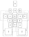
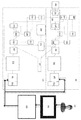
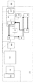
도 1은 휴대용 전력 관리 시스템에서의 컴포넌트들의 변형을 예시한다.
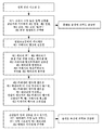
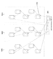
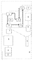
도 2a는 휴대용 전력 관리 시스템의 에너지를 충전하고 저장하는 방법을 설명하는 흐름도의 변형을 예시한다.
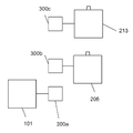
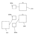
도 2b 및 도 2c는 배터리들을 충전하기 위해 커패시터 뱅크들을 회전시키는 변형을 예시한다.
도 3a는 전원이 수동으로 선택되는 방법의 변형을 예시한다.
도 3b는 전원이 제1 배터리 충전 블록상에서 자동으로 선택되는 방법의 변형을 예시한다.
도 3c는 전원이 제2 배터리 충전 블록상에서 자동으로 선택되는 방법의 변형을 예시한다.
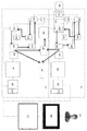
도 4는 배터리를 충전하는 전원의 변형을 예시한다.
도 5는 커패시터 뱅크들의 물리적 연결들의 변형을 예시한다.
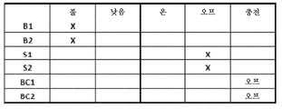
도 6a는 제1 배터리가 완전히 충전될 수 있고 제2 배터리가 낮은 충전을 가질 수 있는 논리 테이블의 변형을 예시한다.
도 6b 및 도 6c는 제1 배터리가 충전되지 않는 동안 제2 배터리를 충전하는 방법의 변형을 예시한다.
도 7a는 제1 배터리가 낮은 충전을 가질 수 있고 제2 배터리가 완전히 충전될 수 있는 논리 테이블의 변형을 예시한다.
도 7b 및 도 7c는 제2 배터리가 충전되지 않는 동안 제1 배터리를 충전하는 방법의 변형을 예시한다.
도 8a는 제1 배터리가 낮은 충전을 가질 수 있고 제2 배터리가 낮은 충전을 가질 수 있는 논리 테이블의 변형을 예시한다.
도 8b는 제1 배터리 및 제2 배터리를 충전하는 방법의 변형을 예시한다.
도 9a는 제1 배터리가 완전히 충전될 수 있고 제2 배터리가 완전히 충전될 수 있는 논리 테이블의 변형을 예시한다.
도 9b는 제1 배터리 및 제2 배터리를 충전하지 않는 방법의 변형을 예시한다.
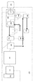
도 10a 및 도 10b는 자동 온도 관리 회로의 흐름도 및 블록도의 변형을 예시한다.
도 11은 위성 네비게이션 수신기의 블록도의 변형을 예시한다.Figure 1 illustrates a variation of components in a portable power management system.
2A illustrates a variation of a flow diagram illustrating a method for charging and storing energy in a portable power management system.
Figures 2B and 2C illustrate a variation that rotates capacitor banks to charge batteries.
Figure 3A illustrates a variation of how the power source is manually selected.
3B illustrates a variation of the manner in which the power source is automatically selected on the first battery charging block.
3C illustrates a variation of the manner in which the power source is automatically selected on the second battery charging block.
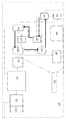
4 illustrates a variation of the power source for charging the battery.
Figure 5 illustrates a variation of the physical connections of the capacitor banks.
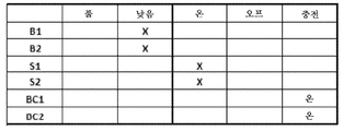
6A illustrates a variation of a logical table in which a first battery can be fully charged and a second battery can have a low charge.
6B and 6C illustrate a variation of the method of charging the second battery while the first battery is not being charged.
7A illustrates a variation of the logical table in which the first battery can have a low charge and the second battery can be fully charged.
Figures 7B and 7C illustrate a variation of the method of charging the first battery while the second battery is not being charged.
8A illustrates a variation of a logical table in which a first battery can have a low charge and a second battery can have a low charge.
8B illustrates a variation of the method of charging the first battery and the second battery.
9A illustrates a variation of a logical table in which a first battery can be fully charged and a second battery can be fully charged.
9B illustrates a variation of the method of not charging the first battery and the second battery.
10A and 10B illustrate a flow diagram and a variation of the block diagram of the automatic temperature management circuit.
11 illustrates a variation of a block diagram of a satellite navigation receiver.
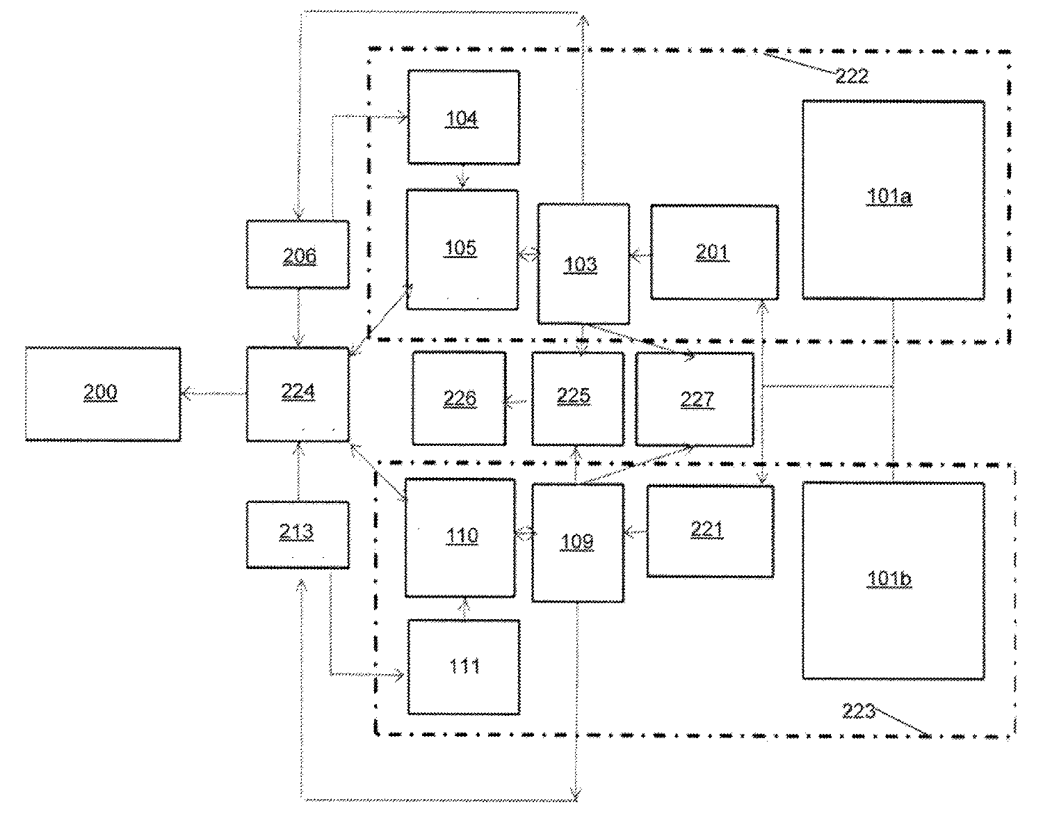
도 1은 전력 관리 시스템(100)이 높은 가용도(예를 들어, 적어도 2개 이상의 배터리들)의 GPS 추적 전력 관리 시스템일 수 있다는 것을 예시한다. 얇은 라인들은 컴포넌트들 사이의 연결들을 나타낼 수 있다. 두꺼운 화살표들은 전류 흐름을 나타낼 수 있다. 전력 관리 시스템(100)은 휴대용일 수 있다. 전력 관리 시스템(100)은 전원(101), 위성 네비게이션 수신기(227), 열 컨트롤(225), 냉각 엘리먼트(226), 전력 스위치 블록(224), 제1 배터리(206), 제2 배터리(213), 제1 배터리 충전 블록(222), 제2 배터리 충전 블록(223), 또는 이들의 임의의 조합을 가질 수 있다.1 illustrates that the power management system 100 may be a GPS tracking power management system of high availability (e.g., at least two or more batteries). Thin lines may represent connections between components. Thick arrows can indicate current flow. The power management system 100 may be portable. The power management system 100 includes a
전력 관리 시스템(100)은 적어도, 제1 전원(101a), 제2 전원(101b), 제3 전원, 제4 전원, 및/또는 제5 전원을 가질 수 있다. 제1 전원(101a)과 제2 전원(101b)은 서로 연결될 수 있다(예를 들어, 전기적으로 연결될 수 있고, 전류가 일 방향으로 흐르도록 전기적으로 연결될 수 있거나, 전류가 양방향들로 흐르도록 전기적으로 연결될 수 있거나, 물리적으로 연결될 수 있다). 전원 입력들은 1.5V DC, 2.7V DC, 3V DC, 3.3V DC, 5V DC, 6V DC, 7.5V DC, 9V DC, 12V DC, 또는 이들의 임의의 조합일 수 있다. 전원들(101)에 대한 조합된 입력 전력은 약 70와트와 약 100와트 사이일 수 있다. 제1 전원(101a) 및 제2 전원(101b)은 상이한 전압들을 가질 수 있다. 제1 전원(101a) 및 제2 전원(101b)은 동일한 전압들을 가질 수 있다. 전원(101)은 자동차 교류발전기, AC 전원, 태양 전지판들, 풍력 터빈들, 다른 DC 전원들, 고정된 라인들, 고정된 라인들로부터의 AC-DC 컨버터들, 발전기들, 다른 대안의 에너지원들, 또는 이들의 임의의 조합을 포함할 수 있다.The power management system 100 may have at least a
위성 네비게이션 수신기는 글로벌 포지셔닝 시스템 칩, 글로벌 포지셔닝 시스템 수신기, 글로벌 포지셔닝 시스템 송신기, 예를 들어, 글로벌 포지셔닝 시스템(GPS) 송신기(227)일 수 있다. GPS 송신기(227)는 디바이스(200)(예를 들어, 부하, 휴대용 비디오 보안 유닛)에 연결될 수 있다. GPS 송신기는 제1 배터리 충전 블록(222) 및/또는 제2 배터리 충전 블록(223)에 연결될 수 있다. GPS 송신기는 제1 배터리 충전 블록(222)과 제2 배터리 충전 블록(223) 사이에 위치될 수 있다. GPS 송신기(227)는 전력 관리 시스템(100) 및/또는 디바이스(200)의 위치를 추적할 수 있다. GPS 송신기(227)의 위치는 임의의 컴퓨터, 브라우저, 모바일 디바이스, 애플리케이션, GPS 송신기(227)에 의해 지원된 그래픽 사용자 인터페이스, 또는 이들의 임의의 조합 상에 디스플레이될 수 있다. GPS 송신기(227)에는 전원(101), 제1 배터리(206), 제2 배터리(213), 또는 이들의 임의의 조합에 의해 전력이 공급될 수 있다.The satellite navigation receiver may be a global positioning system chip, a global positioning system receiver, a global positioning system transmitter, e.g., a Global Positioning System (GPS)
열 컨트롤(225에는 전원(101), 제1 배터리(206), 제2 배터리(213), 또는 이들의 임의의 조합에 의해 전력이 공급될 수 있다. 열 컨트롤(225)은 센서들일 수 있다. 센서들은 전력 관리 시스템(100) 및/또는 디바이스(200)의 온도를 검출할 수 있다.The
냉각 엘리먼트들(226)은 열 컨트롤(225)에 연결될 수 있다. 냉각 엘리먼트들(226)은 열전 펠티에 냉각 모듈들, 압전판들, 팬들, 액체, 겔, 또는 이들의 임의의 조합일 수 있다. 냉각 엘리먼트(226)는 열 컨트롤(225)의 세팅들에 기초하여 활성화될 수 있다.Cooling
전력 스위치 블록(224)은 제11 릴레이 엘리먼트(211) 및/또는 제4 릴레이 엘리먼트(209)를 가질 수 있다. 전력 스위치 블록(224)은 디바이스(200)에 연결될 수 있다. 전력 스위치 블록(224)은 디바이스(200)로의 제1 배터리(206)의 전류 흐름 및/또는 제2 배터리(213)의 전류 흐름을 제어할 수 있다.The
전력 관리 시스템(100)은 적어도 하나, 2개, 3개, 4개, 5개 이상의 배터리들을 가질 수 있다. 제1 배터리(206) 및 제2 배터리(213)는 전력 스위치 블록(224) 및/또는 릴레이 엘리먼트들에 연결될 수 있다. 배터리들(206, 213)은 풀 배터리 전압을 가질 수 있다. 제1 풀 배터리 전압은 제2 풀 배터리 전압과 상이할 수 있다. 제2 풀 배터리 전압은 제1 풀 배터리 전압과 동일할 수 있다. 제1 배터리(206)는 제1 배터리 전압을 가질 수 있다. 제2 배터리(213)는 제2 배터리 전압을 가질 수 있다. 제1 배터리 전압은 제2 배터리 전압과 동일할 수 있다. 제1 배터리 전압은 제2 배터리 전압과 상이할 수 있다. 배터리 전압은 전압 검출기들(207, 216)에 의해 판독된 전압일 수 있다. 풀 배터리 전압 및/또는 배터리 전압은 약 1.5V, 약 2.7V, 약 3V, 약 3.3V, 약 5V, 약 6V, 약 7.5V, 약 9 V, 약 12V, 또는 이들의 임의의 조합일 수 있다. 예를 들어, 제1 풀 배터리 전압은 12V일 수 있는 반면에 제2 풀 배터리 전압은 2.7V일 수 있다. 제1 풀 배터리 전압은 12V일 수 있고, 제2 풀 배터리 전압은 12V일 수 있다. 배터리들(206, 213)은 12V 리튬 이온 배터리일 수 있다.The power management system 100 may have at least one, two, three, four, five or more batteries. The
제1 배터리 충전 블록(222)은 제1 자동 전력 관리 회로(201)를 가질 수 있다. 제1 자동 전력 관리 회로(201)는 전원(101)에 연결될 수 있다. 제1 자동 전력 관리 회로(201)는 다수의 입력 전원들(101)을 관리할 수 있다. 제1 자동 전력 관리 회로(201)는 논리 테이블 제어 방법을 가질 수 있다. 논리 테이블 제어 방법은 적어도 하나 이상의 전원들(101)을 선택할 수 있다. 제1 자동 전력 관리 회로(201)는 배터리들(206, 213) 및/또는 커패시터 뱅크들(300)을 지속적으로 충전할 수 있다. 예를 들어, 제1 자동 전력 관리 회로(201)는 배터리들(206, 213) 및/또는 커패시터 뱅크들(300)을 충전하기 위해 다수의 전원들(101)을 조합할 수 있다. 제1 자동 전력 관리 회로(201)는 디바이스(200)에 대한 전력을 조정할 수 있다.The first
제1 배터리 충전 블록(222)은 제1 슈퍼 충전 회로(103)를 가질 수 있다. 제1 슈퍼 충전 회로(103)는 제1 슈퍼 커패시터 충전 회로(202) 및/또는 제1 리튬 이온 충전 회로(203)를 가질 수 있다. 슈퍼 커패시터 충전 회로(202)의 출력이 리튬 이온 충전 회로(203)의 입력에 연결될 수 있다. 제1 슈퍼 충전 회로(103), 제1 슈퍼 충전 커패시터 회로(202), 제1 리튬 이온 충전 회로(203), 또는 이들의 임의의 조합이 자동 전력 관리 회로(201), GPS 송신기(227), 열 컨트롤(225), 제1 배터리(206), 또는 이들의 임의의 조합에 연결될 수 있다.The first
제1 슈퍼 충전 회로(103)는 전원(101)으로부터 커패시터들(302)(예를 들어, 전류의 고속 충전 및 방전을 위해 설계된 커패시터들, 슈퍼커패시터들, 울트라커패시터들)로의 전류를 바로 저장할 수 있다. 제1 슈퍼 충전 회로(103)는 커패시터들(302)로부터의 전류를 빠르게 충전 및 방전할 수 있다. 제1 슈퍼 충전 회로(103)는 1V DC, 2V DC, 2.7V DC, 3V DC, 또는 이들의 임의의 조합의 증분으로 전류를 충전 및/또는 방전할 수 있다. 제1 슈퍼 충전 회로(103)는 전류의 일정한 방전을 제1 배터리(206)에 제공할 수 있다. 예를 들어, 슈퍼 충전 회로(103)는 출력 전력을 12V DC 리튬 이온 배터리들 및 2.7V 커패시터들에 동시에 저장할 수 있다. 슈퍼 충전 회로(103)는 약 70와트로부터 약 100와트까지의 조합된 입력 전력을 갖는 에너지를 충전 및/또는 저장할 수 있다.The
제1 슈퍼 충전 회로(103), 제1 슈퍼 충전 커패시터 회로(202), 제1 리튬 이온 충전 회로(203), 또는 이들의 임의의 조합은 (커패시터들(302) 및/또는 배터리(206)에 전류를 전송할 때 동시에) 전류(예를 들어, 출력 전류)를 GPS 송신기(227) 및/또는 열 컨트롤(225)에 전송할 수 있다.The first
제1 배터리 충전 블록(222)은 제1 전류 밸런스 관리 회로(105)를 가질 수 있다. 제1 전류 밸런스 관리 회로(105)는 제1 슈퍼 충전 회로(103) 및/또는 전력 스위치 블록(224)에 연결될 수 있다. 제1 전류 밸런스 관리 회로(105)는 제1 릴레이 엘리먼트(204), 제2 릴레이 엘리먼트(205), 제3 릴레이 엘리먼트(예를 들어, 제1 전압 검출기(207)), 제4 릴레이 엘리먼트(209), 제5 릴레이 엘리먼트(210), 또는 이들의 임의의 조합을 가질 수 있다. 릴레이 엘리먼트들은 서로 연결될 수 있다. 릴레이 엘리먼트들은 제1 슈퍼 충전 회로(103) 또는 전력 관리 시스템(100)의 임의의 다른 컴포넌트에 연결될 수 있다.The first
제1 배터리 충전 블록(222)은 제1 전압 검출기(207)를 가질 수 있다. 제1 전압 검출기(207)는 저전압 검출기일 수 있다. 제1 전압 검출기(207)는 제1 전류 밸런스 관리 회로(105), 제1 배터리(206), 임의의 릴레이 엘리먼트, 또는 이들의 임의의 조합에 연결될 수 있다. 제1 전압 검출기(207)는 제1 전류 밸런스 관리 회로(105) 전 또는 후에 연결될 수 있다. 제1 전압 검출기(207)는 제1 슈퍼 충전 회로(103) 전 또는 후에 연결될 수 있다. 제1 전압 검출기(207)는 제1 자동 전력 관리 회로(201) 전 또는 후에 연결될 수 있다. 제1 전압 검출기(207)는 전원(101) 이후에 연결될 수 있다. 제1 전압 검출기(107)는 전압을 검출할 수 있다. 제1 전압 검출기(207)는 제1 배터리(206)로부터의 전압을 검출할 수 있다. 제1 전압 검출기(207)는 설정 기준 전압(후술함)을 가질 수 있다. 제1 전압 검출기(207)는 전압 및/또는 전류를 디스플레이 스크린상에 디스플레이할 수 있다.The first
제1 배터리 충전 블록(222)은 제1 출력 스위치를 가질 수 있다. 전압 검출기는 제1 출력 스위치를 가질 수 있다. 전력 스위치는 제1 출력 스위치를 가질 수 있다. 제1 출력 스위치는 배터리의 충전을 인에이블하거나 디스에이블할 수 있다. 출력 스위치는 설정 기준 전압을 가질 수 있다.The first
전력 관리 시스템(100)은 전류 센서들을 가질 수 있다. 전류 센서들은 전류를 검출할 수 있다. 전류 센서들은 자동 전력 관리 회로(201) 이전에 위치될 수 있다. 전류 센서들은 전류 관리 회로(105) 전 또는 후에 위치될 수 있다.The power management system 100 may have current sensors. Current sensors can detect current. The current sensors may be located prior to the automatic
제2 배터리 충전 블록(223)은 제2 자동 전력 관리 회로(221), 제2 슈퍼 충전 회로(109), 제2 전류 밸런스 관리 회로(110), 또는 이들의 임의의 조합을 가질 수 있다. 제2 자동 전력 관리 회로(221)는 제6 릴레이 엘리먼트(218), 제7 릴레이 엘리먼트(217), 제8 릴레이 엘리먼트(예를 들어, 제2 전압 검출기(216)), 제9 릴레이 엘리먼트(215), 제10 릴레이 엘리먼트(214), 제2 출력 스위치, 또는 이들의 임의의 조합을 가질 수 있다. 제2 배터리 충전 블록(223)의 컴포넌트들은 제1 배터리 충전 블록(222)의 컴포넌트들과 유사할 수 있다.The second
제1 배터리 충전 블록(222)은 프라이머리 충전 블록일 수 있다. 제1 배터리 충전 블록(222)은 세컨더리 충전 블록일 수 있다. 제2 배터리 충전 블록(223)은 프라이머리 충전 블록일 수 있다. 제2 배터리 충전 블록(223)은 세컨더리 충전 블록일 수 있다. 제1 배터리 충전 블록(222) 및 제2 배터리 충전 블록(223)은 동일한 전자 기판상에 있을 수 있다. 제1 배터리 충전 블록(222) 및 제2 배터리 충전 블록(223)은 상이한 전자 기판들상에 있을 수 있다. 예를 들어, 제1 자동 전력 관리 회로(201), 제1 슈퍼충전 회로(103), 제1 전류 밸런스 관리 회로(105), 제1 전압 검출기(207), 또는 이들의 임의의 조합이 제1 전자 기판상에 있을 수 있다. 제2 자동 전력 관리 회로(221), 제2 슈퍼충전 회로(109), 제2 전류 밸런스 관리 회로(110), 제2 전압 검출기(216), 또는 이들의 임의의 조합이 제2 전자 기판상에 있을 수 있다. 전원(101), 냉각 엘리먼트(226), 열 컨트롤(225), GPS 송신기(227), 전력 스위치 블록(224), 제1 배터리(206), 제2 배터리(213), 디바이스(200), 또는 이들의 임의의 조합이 제1 전자 기판, 제2 전자 기판, 제3 전자 기판, 또는 이들의 임의의 조합상에 있을 수 있다. 전원(101), 냉각 엘리먼트(226), 열 컨트롤(225), GPS 송신기(227), 전력 스위치 블록(224), 제1 배터리(206), 제2 배터리(213), 디바이스(200), 또는 이들의 임의의 조합이 제1 배터리 충전 블록(222) 및/또는 제2 배터리 충전 블록(223)에 연결될 수 있다.The first
전류 밸런스 관리 회로들(105, 110)은 전류를 제어할 수 있다. 전류 밸런스 관리 회로들(105, 110)은 논리 테이블 조건들에 매칭하도록 전류 및 전압 레벨들을 생성할 수 있다. 전류 밸런스 관리 회로들(105, 110)은 제1 배터리(206)와 제2 배터리(213) 사이의 전류 방전을 밸런싱할 수 있다. 전원(101)이 이용불가능하고, 제1 배터리(206) 및 제2 배터리(213)가 모두 설정 기준 전압들(예를 들어, 풀 배터리 전압, 최적의 배터리 전압) 아래일 때, 전류 밸런스 관리 회로들(105, 110)은 디바이스(200)에 전력을 공급하기 위해 배터리 전류를 종속접속(cascade)하고 그리고/또는 조합할 수 있다. 예를 들어, 전원(101)으로부터의 에너지가 불충분한 경우에, 전류 밸런스 관리 회로들(105, 110)은 디바이스(200)에 전력을 공급하기 위해 제1 배터리(206)로 스위칭할 수 있다. 제1 배터리(206)가 설정 기준 전압 아래인 경우에, 전류 밸런스 관리 회로들(105, 110)은 디바이스(200)에 전력을 공급하기 위해 제2 배터리(213)로 스위칭할 수 있다. 제2 배터리(213)가 설정 기준 전압 아래로 떨어지면, 제1 배터리(206) 및 제2 배터리(213)로부터의 나머지 전류가 디바이스(200)에 전력을 제공하기 위해 조합될 수 있다.The current
설정 기준 전압은 약 0V로부터 약 12V, 예를 들어, 약 1 V, 약 2V, 약 3V, 약 4V, 약 5V, 약 6V, 약 7V, 약 8V, 약 9V, 약 10V, 약 11V, 또는 약 11.5V일 수 있다. 설정 기준 전압은 제1 배터리(206) 및 제2 배터리(213)에 대해 상이할 수 있다. 설정 기준 전압은 제1 배터리(206) 및 제2 배터리(213)에 대해 동일할 수 있다.The set reference voltage may range from about 0 V to about 12 V, for example about 1 V, about 2 V, about 3 V, about 4 V, about 5 V, about 6 V, about 7 V, about 8 V, about 9 V, about 10 V, Lt; / RTI > The set reference voltage may be different for the
도 2a는 전력 관리 시스템(100)이 활성화될 때, 어느 전원이 가장 높은 입력 전류(예를 들어, 최적의 입력 전류)를 갖는지에 기초하여 전력 관리 시스템(100)이 전원들(101a, 101b) 사이에서 선택할 수 있다는 것을 예시한다. 전원(101)은 디바이스(200)에 직접 전력을 공급할 수 있다. 동시에, 전력 관리 시스템(100)은 전원(101)으로부터 제1 커패시터 뱅크(300a)로 에너지를 전송할 수 있다. 전원(101)으로부터 제1 커패시터 뱅크(300a)로의 에너지의 전송과 동시에 또는 상이한 시간에, 전력 관리 시스템(100)은 도 2a 및 도 2b에 도시되어 있는 바와 같이 제1 배터리(206) 전압이 설정 기준 전압 아래로 떨어질 때 제2 커패시터 뱅크(300b)로부터의 전류를 제1 배터리(206)에 방전할 수 있다. 동시에 또는 상이한 시간에, 전력 관리 시스템(100)은 도 2a 및 도 2b에 도시되어 있는 바와 같이 제2 배터리(213)가 설정 기준 전압 아래로 떨어질 때 제3 커패시터 뱅크(300c)로부터의 전류를 제2 배터리(213)에 방전할 수 있다. 제2 커패시터 뱅크(300b)가 제1 배터리(206)로 더 이상 전류를 방전하지 않거나 커패시터 뱅크 임계치(예를 들어, 최적의 커패시터 전압) 아래로 떨어지지 않으면, 전력 관리 시스템(100)은 도 2c에 도시되어 있는 바와 같이 제1 커패시터 뱅크(300a)가 제1 배터리(206)에 전류를 방전하고 전원(101)이 제2 커패시터 뱅크(300b)에 에너지를 전송하도록 제1 커패시터 뱅크(300a)를 제2 커패시터 뱅크(300b)와 스위칭할 수 있다. 전원들(101)이 입력 전류를 갖지 않으면, 전력 관리 시스템(100)은 어느 배터리가 가장 높은 전압을 갖는지에 기초하여 디바이스(200)에 전력을 공급하기 위해 제1 배터리(206) 및/또는 제2 배터리(213) 사이에서 선택할 수 있다. 전력 관리 시스템(100)은 배터리들 및 커패시터들을 지속적으로(예를 들어, 연속적으로; 무정전) 충전할 수 있다. 전력 관리 시스템(100)은 디바이스(200)에 지속적으로 전력을 공급할 수 있다. 커패시터 뱅크 임계치는 0V와 약 3V 사이, 예를 들어, 약 1V, 약 2V, 약 2.5V, 또는 약 3V일 수 있다.2A illustrates how the power management system 100 determines whether
하나의 컴포넌트 또는 컴포넌트들의 조합이 이러한 결과를 달성할 수 있다. 예를 들어, 자동 전력 관리 회로들(201, 221)은 가장 높은 입력을 갖는 전원(101)을 선택할 수 있다. 슈퍼 충전 회로들(103, 109)은 전원(101)으로부터의 에너지를 커패시터 뱅크(300)에 전송할 수 있다. 전류 관리 회로들(105, 110)은 디바이스(200)에 대한 전력을 관리할 수 있다.A single component or combination of components can achieve this result. For example, the automatic
도 3a는 전력 관리 시스템(100)이 수동 오버라이드(override) 회로(MOC)를 가질 수 있다는 것을 예시한다. MOC는 자동 전력 관리 회로들(201, 221)내에 있을 수 있다. 전력 관리 시스템(100)은 사용자(227)가 전원(101)을 수동으로 선택하게 할 수 있다. 사용자(227)는 전원(101)을 선택하기 위해 그래픽 사용자 인터페이스(GUI: 228)를 사용할 수 있다. GUI(228)는 소프트웨어 명령을 애플리케이션 프로그래밍 인터페이스(API: 229)에 전송할 수 있다. API(229)는 저레벨 I/O 제어 신호를 작성할 수 있다. API(229)는 저레벨 I/O 제어 신호를 자동 전력 관리 회로들(201, 221)에 전송할 수 있다. 자동 전력 관리 회로들(201, 221)은 전원(101)을 선택하기 위해 수동 오버라이드 회로를 활성화시킬 수 있다. MOC는 자동 전력 관리 회로들(201, 221)의 자동-선택을 디스에이블(예를 들어, 오버라이드)할 수 있다.Figure 3A illustrates that the power management system 100 may have a passive override circuit (MOC). The MOC may be in the automatic
도 3b 및 도 3c는 전력 관리 시스템(100)이 가장 높은 입력 전류를 갖는 전원을 선택할 수 있다는 것을 예시한다. 자동 전력 관리 회로들(201, 221)은 각각의 전원들(101a, 101b)의 입력 전류를 연속적으로 결정할 수 있다. 자동 전력 관리 회로들(201, 221)은 각각의 전원들(101a, 101b)의 입력 전류를 주기적으로 결정할 수 있다. 예를 들어, 자동 전력 관리 회로들(201, 221)은 약 1분, 2분, 30분, 45분, 또는 1시간 마다 전원(101a, 101b)의 입력 전류를 결정할 수 있다. 자동 전력 관리 회로들(201, 221)에 의해 선택된 전원(101)은 제1 배터리(206), 제2 배터리(213), 디바이스(200), 또는 이들의 임의의 조합을 충전할 수 있다.3B and 3C illustrate that the power management system 100 can select a power source having the highest input current. The automatic
도 3b는 전원들(101a, 101b)이 자동 전력 관리 회로(201)의 입력에 연결될 수 있다는 것을 예시한다. 전원(101)은 전류를 자동 전력 관리 회로(201)에 전송할 수 있다. 자동 전력 관리 회로(201)로부터의 전류는 슈퍼 커패시터 충전 회로(202)에 전송될 수 있다. 슈퍼 커패시터 충전 회로(202)는 전원(101)으로부터의 전류를 저장할 수 있다. 슈퍼 커패시터 충전 회로(202)는 전류를 리튬 이온 충전 회로(203)에 방전할 수 있다. 리튬 이온 충전 회로(203)는 제1 릴레이 엘리먼트(204)를 트리거링할 수 있다. 제1 릴레이 엘리먼트(204)는 제4 릴레이 엘리먼트(209)로 전류를 스위칭할 수 있다. 제1 릴레이 엘리먼트(204)는 제1 배터리(206)에 전류를 전송할 수 있다. 제1 배터리(206)는 전력 스위치(224)에 전류를 전송할 수 있다. 전력 스위치(224)는 디바이스(200)에 전력을 전송할 수 있다. 전원(101)은 GPS 송신기(227)에 전력을 공급할 수 있다.3B illustrates that the
도 3c는 전원들(101a, 101b)이 자동 전력 관리 회로(221)의 입력에 연결될 수 있다는 것을 예시한다. 전원(101)은 전류를 자동 전력 관리 회로(221)에 전송할 수 있다. 자동 전력 관리 회로(221)로부터의 전류는 슈퍼 커패시터 충전 회로(220)에 전송될 수 있다. 슈퍼 커패시터 충전 회로(220)는 전원(101)으로부터의 입력 전류를 저장할 수 있다. 슈퍼 커패시터 충전 회로(220)는 전류를 리튬 이온 충전 회로(219)에 방전할 수 있다. 리튬 이온 충전 회로(219)는 제6 릴레이 엘리먼트(218)를 트리거링할 수 있다. 제6 릴레이 엘리먼트(218)는 제9 릴레이 엘리먼트(215)를 통해 전류를 스위칭할 수 있다. 제6 릴레이 엘리먼트(218)는 제2 배터리(213)에 전류를 전송할 수 있다. 제2 배터리(206)는 전력 스위치(224)에 전류를 전송할 수 있다. 전력 스위치(224)는 디바이스(200)에 전력을 전송할 수 있다.3C illustrates that the
도 4는 전원들(101a, 101b, 101c), 게이트(304), 커패시터들(302), 커패시터 뱅크(300), 배터리들(206, 213), 또는 이들의 임의의 조합을 예시한다. 전원(101)은 태양 전지판들, 풍력 터빈들, 또는 고정된 라인일 수 있다.4 illustrates
전원(101)은 전류를 게이트(304)에 전송할 수 있다. 게이트(304)는 전원(101)으로부터의 전류를 커패시터 뱅크(300)에 전송할 수 있다. 게이트(304)는 마이크로프로세서일 수 있다. 게이트(304)는 스위치일 수 있다. 게이트(304)는 후술하는 바와 같이 비교기들과 같은 논리 게이트들일 수 있다. 게이트(304)는 릴레이 엘리먼트들을 가질 수 있다. 게이트(304)는 전원들(101)의 전류들을 비교할 수 있다. 게이트(304)는 가장 높은 전류를 갖는 전원(101)을 선택할 수 있다.The
전력 관리 시스템(100)은 적어도 하나, 2개, 3개, 4개, 5개 이상의 커패시터 뱅크들(300)을 가질 수 있다. 커패시터 뱅크(300)는 적어도 하나, 2개, 3개, 4개, 5개, 6개 이상의 커패시터들(302)을 가질 수 있다. 커패시터 뱅크(300)는 약 1V와 16.2V 사이, 예를 들어, 약 2.7V, 약 5.4V, 약 8.1V, 약 13.5V, 또는 약 16.2V의 총 전압을 가질 수 있다. 커패시터 뱅크들(300)은 동일한 전압들 또는 상이한 전압들을 가질 수 있다. 커패시터들(302)은 약 0.5V와 약 6V 사이, 예를 들어, 약 1V, 약 2.7V, 약 3V, 또는 약 6V의 전압을 가질 수 있다. 커패시터들(302)은 동일한 전압들 또는 상이한 전압들을 가질 수 있다. 예를 들어, 전력 관리 시스템(100)은 제1 커패시터 뱅크(300a), 제2 커패시터 뱅크(300b), 및 제3 커패시터 뱅크(300c)를 가질 수 있다. 각각의 커패시터 뱅크(300)는 5개의 2.7V 커패시터들(302)을 가질 수 있다. 커패시터들은 직렬로 연결될 수 있다. 커패시터들은 병렬로 연결될 수 있다. 커패시터 뱅크(300)는 전류를 배터리들(206, 213)에 방전할 수 있다. 커패시터 뱅크(300)는 전류를 분압기 및./또는 전압 제한기에 전송할 수 있다. 분압기 및/또는 전압 제한기는 전류를 배터리들(206, 213)에 전송할 수 있다.The power management system 100 may have at least one, two, three, four, five or more
도 5는 전력 관리 시스템(100)이 전압 레귤레이터(306)를 가질 수 있다는 것을 예시한다. 커패시터(302)는 전압 레귤레이터(306)의 출력에 연결될 수 있다. 커패시터 뱅크들(300) 각각에서의 커패시터들(302)은 직렬로 연결될 수 있다. 커패시터 뱅크들(300) 각각에서의 커패시터들(302)은 병렬로 연결될 수 있다. 전압 레귤레이터 출력(306)은 2.7V dc 증분으로 출력 전압 레벨을 스택(stack)할 수 있다. 커패시터 뱅크들(300)에서의 전압은 2.7V DC 증분으로 수신되고 그리고/또는 방전될 수 있다.FIG. 5 illustrates that the power management system 100 may have a
도 6a 내지 도 9b는 전력 스위칭 방법이 논리 테이블들에서의 명령어들에 기초할 수 있다는 것을 예시한다. 논리 테이블에서의 명령어들은 다수의 입력 전원들(101)로부터 가장 높은 입력 전류원을 자동 선택하도록 시스템에 명령할 수 있고, 동시에, 일정한 그리고 무정전 전력을 디바이스(200)에 전달하도록 시스템에 명령할 수 있다. 논리 테이블은 제1 배터리(206), 제2 배터리(213), 제1 스위치(S1), 제2 스위치(S2), 제1 배터리 충전 블록(222), 및 제2 배터리 충전 블록(223)의 상태(예를 들어, 판독된 시스템 상태)를 나타낼 수 있다. 논리 테이블들은 시스템에서 마이크로프로세서에 의해 실행된 메모리에서의 소프트웨어 명령들일 수 있다. 논리 테이블들은 마더보드와 같은 시스템의 전자기기의 고체 상태에서 스위치들(예를 들어, 논리 게이트들, 예를 들어, AND 게이트들, OR 게이트들, NOT 게이트들, NAND 게이트들, NOR 게이트들, EOR 게이트들, ENOR 게이트들, 또는 이들의 조합들과 같은 비교기들)과 같은 하드웨어 아키텍처들을 나타낼 수 있다. 논리 테이블들은 범용 I/O(GIPO) 회로상에서 실행될 수 있다. GIPO는 전력 관리 시스템(100)에 신호들을 전송할 수 있고 전력 관리 시스템(100)으로부터 신호들을 수신할 수 있다. 논리 테이블 소프트웨어 명령들 및/또는 논리 테이블 하드웨어는 자동 전력 관리 회로들(201, 221), 전류 관리 회로들(105, 110), 또는 전력 관리 시스템(100)의 임의의 다른 컴포넌트상에 위치될 수 있고 그리고/또는 실행될 수 있다. 논리 테이블들은 커패시터들로부터 배터리들로 전류를 라우팅하도록 스위치들을 제어할 수 있다. 논리 테이블들은 예를 들어, 시스템의 컴포넌트들에 지시할 수 있고, 전류를 라우팅할 수 있고, 시스템의 엘리먼트들을 제어할 수 있거나, 이들의 임의의 조합일 수 있다. 배터리 전압이 설정 기준 전압 이상일 때, 배터리들(206, 213)은 완전하게 충전될 수 있다. 배터리 전압이 설정 기준 전압 이하일 때, 배터리들(206, 213)은 낮은 충전을 가질 수 있다.Figures 6A-B illustrate that the power switching method may be based on instructions in logical tables. The instructions in the logical table can instruct the system to automatically select the highest input current source from
도 6a는 제1 배터리(206) 충전이 풀일 때, 제1 스위치(S1)가 턴 오프될 수 있다는 것을 예시한다. 제2 배터리(213) 충전이 낮을 때, 제2 스위치(S2)는 턴 온될 수 있다. 제1 스위치(S1)를 턴 오프하는 것은 제1 배터리 충전 블록(222)의 충전을 턴 오프할 수 있다. 제2 스위치(S2)를 턴 온하는 것은 제2 배터리 충전 블록(223)의 충전을 턴 온할 수 있다.6A illustrates that when the
도 6b는 제1 배터리(206)가 전압을 제1 전압 검출기(207)에 전송할 수 있다는 것을 예시한다. 제1 전압 검출기(207)가 설정 기준 전압 이상의 전압을 검출할 때, 제1 출력 스위치는 턴 오프될 수 있다. 제1 출력 스위치가 턴 오프될 때, 제4 릴레이 엘리먼트(209)는 제1 배터리(206)를 충전하는 것으로부터 디스에이블(예를 들어, 트리거링)될 수 있다. 제4 릴레이 엘리먼트(209)는 제5 릴레이 엘리먼트(210)를 디스에이블할 수 있다. 제5 릴레이 엘리먼트(210)는 제1 릴레이 엘리먼트(204)를 디스에이블할 수 있다. 제1 릴레이 엘리먼트(204)는 제2 릴레이 엘리먼트(205)를 디스에이블할 수 있다. 제2 릴레이 엘리먼트(205)가 디스에이블되는 동안, 슈퍼 커패시터 충전 회로(202)는 전류를 제1 전류 밸런스 제어 릴레이(208)에 전송할 수 있다. 전류 밸런스 제어 릴레이(208)는 전류를 제11 릴레이 엘리먼트(211)에 전송할 수 있다. 제11 릴레이 엘리먼트(211)는 디바이스(200)에 전력을 공급하기 위해 전류를 전송할 수 있다. 디스에이블은 전류 흐름을 중지시키는 것을 의미할 수 있다.FIG. 6B illustrates that the
도 6c는 제2 배터리(213)가 전압을 제2 전압 검출기(216)에 전송할 수 있다는 것을 예시한다. 제2 전압 검출기(216)가 설정 기준 전압 미만의 전압을 검출할 때, 제10 릴레이 엘리먼트(214)가 인에이블될 수 있다. 제10 릴레이 엘리먼트(214)가 인에이블될 때, 제10 릴레이 엘리먼트(214)는 제9 릴레이 엘리먼트(215)를 인에이블할 수 있다. 제9 릴레이 엘리먼트(215)는 제2 배터리(213)를 충전하기 위해 제6 릴레이 엘리먼트(218)를 인에이블할 수 있다. 제6 릴레이 엘리먼트(218)는 제7 릴레이 엘리먼트(217)에 전류를 전송할 수 있다. 제7 릴레이 엘리먼트(217)는 제2 배터리(213)에 전류를 전송할 수 있다. 인에이블은 전류 흐름을 허용하는 것을 의미할 수 있다.6C illustrates that the
도 7a는 제2 배터리(213) 충전이 풀일 때, 제2 스위치(S2)가 턴 오프될 수 있다는 것을 예시한다. 제1 배터리(206) 충전이 낮을 때, 제1 스위치(S1)는 턴 온될 수 있다. 제1 스위치(S1)를 턴 온하는 것은 제1 배터리 충전 블록(222)의 충전을 턴 온할 수 있다. 제2 스위치(S2)를 턴 오프하는 것은 제2 배터리 충전 블록(223)의 충전을 턴 오프할 수 있다.7A illustrates that when the
도 7b는 제1 배터리(206)가 전압을 제1 전압 검출기(207)에 전송할 수 있다는 것을 예시한다. 제1 전압 검출기(207)가 설정 기준 전압 미만의 전압을 검출할 때, 제4 릴레이 엘리먼트(209)가 인에이블될 수 있다. 제4 릴레이 엘리먼트(209)가 인에이블될 때, 제4 릴레이 엘리먼트(209)는 제5 릴레이 엘리먼트(210)를 인에이블할 수 있다. 제5 릴레이 엘리먼트(210)는 제1 배터리(206)를 충전하기 위해 제1 릴레이 엘리먼트(204)를 인에이블할 수 있다. 제1 릴레이 엘리먼트(204)는 제2 릴레이 엘리먼트(205)에 전류를 전송할 수 있다. 제2 릴레이 엘리먼트(205)는 제1 배터리(206)에 전류를 전송할 수 있다.FIG. 7B illustrates that the
도 7c는 제2 배터리(213)가 전압을 제2 전압 검출기(216)에 전송할 수 있다는 것을 예시한다. 제2 전압 검출기(216)가 설정 기준 전압 이상의 전압을 검출할 때, 제2 출력 스위치는 턴 오프될 수 있다. 제2 출력 스위치가 턴 오프될 때, 제10 릴레이 엘리먼트(214)는 제2 배터리(213)를 충전하는 것으로부터 디스에이블될 수 있다. 제10 릴레이 엘리먼트(214)는 제6 릴레이 엘리먼트(218)를 디스에이블할 수 있다. 제6 릴레이 엘리먼트(218)는 제7 릴레이 엘리먼트(217)를 디스에이블할 수 있다. 제7 릴레이 엘리먼트(217)는 제12 릴레이 엘리먼트(252)를 디스에이블할 수 있다. 제12 릴레이 엘리먼트(212)는 제2 배터리(213)에 전류를 전달하는 것을 디스에이블할 수 있다. 제11 릴레이 엘리먼트(211)는 디바이스(200)에 전력을 공급하기 위해 제2 배터리(213)로부터 전류를 전송할 수 있다.FIG. 7C illustrates that the
도 8a는 제1 배터리(206) 충전이 낮을 때, 제1 스위치(S1)가 턴 온될 수 있다는 것을 예시한다. 제2 배터리(213) 충전이 낮을 때, 제2 스위치(S2)는 턴 온될 수 있다. 제1 스위치(S1)를 턴 온하는 것은 제1 배터리 충전 블록(222)의 충전을 턴 온할 수 있다. 제2 스위치(S2)를 턴 온하는 것은 제2 배터리 충전 블록(223)의 충전을 턴 온할 수 있다.8A illustrates that when the charge of the
도 8b는 제1 배터리(206)가 전압을 제1 전압 검출기(207)에 전송할 수 있다는 것을 예시한다. 제1 전압 검출기(207)가 설정 기준 전압 미만의 전압을 검출할 때, 제4 릴레이 엘리먼트(209)가 인에이블될 수 있다. 제4 릴레이 엘리먼트(209)가 인에이블될 때, 제4 릴레이 엘리먼트(209)는 제5 릴레이 엘리먼트(210)를 인에이블할 수 있다. 제5 릴레이 엘리먼트(210)는 제1 배터리(206)를 충전하기 위해 제1 릴레이 엘리먼트(204)를 인에이블할 수 있다. 제1 릴레이 엘리먼트(204)는 제2 릴레이 엘리먼트(205)에 전류를 전송할 수 있다. 제2 릴레이 엘리먼트(205)는 제1 배터리(206)에 전류를 전송할 수 있다.FIG. 8B illustrates that the
제2 배터리(213)는 전압을 제2 전압 검출기(216)에 전송할 수 있다. 제2 전압 검출기(216)가 설정 기준 전압 미만의 전압을 검출할 때, 제10 릴레이 엘리먼트(214)가 인에이블될 수 있다. 제10 릴레이 엘리먼트(214)가 인에이블될 때, 제10 릴레이 엘리먼트(214)는 제9 릴레이 엘리먼트(215)를 인에이블할 수 있다. 제9 릴레이 엘리먼트(215)는 제2 배터리(213)를 충전하기 위해 제6 릴레이 엘리먼트(218)를 인에이블할 수 있다. 제6 릴레이 엘리먼트(218)는 제7 릴레이 엘리먼트(217)에 전류를 전송할 수 있다. 제7 릴레이 엘리먼트(217)는 제2 배터리(213)에 전류를 전송할 수 있다.And the
제1 배터리(206) 및 제2 배터리(213)는 동시에 충전할 수 있다. 제1 배터리(206) 및 제2 배터리(213)는 상이한 시간에 충전할 수 있다.The
도 9a는 제1 배터리(206) 충전이 풀일 때, 제1 스위치(S1)가 턴 오프될 수 있다는 것을 예시한다. 제2 배터리(213) 충전이 풀일 때, 제2 스위치(S2)는 턴 오프될 수 있다. 제1 스위치(S21)를 턴 오프하는 것은 제1 배터리 충전 블록(222)의 충전을 턴 오프할 수 있다. 제2 스위치(S2)를 턴 오프하는 것은 제2 배터리 충전 블록(223)의 충전을 턴 오프할 수 있다.9A illustrates that when the
도 9b는 제1 배터리(206)가 전압을 제1 전압 검출기(207)에 전송할 수 있다는 것을 예시한다. 제1 전압 검출기(207)가 설정 기준 전압 이상의 전압을 검출할 때, 출력 스위치는 턴 오프될 수 있다. 출력 스위치가 턴 오프될 때, 제4 릴레이 엘리먼트(209)는 제1 배터리(206)를 충전하는 것으로부터 디스에이블될 수 있다. 제4 릴레이 엘리먼트(209)는 제5 릴레이 엘리먼트(210)를 디스에이블할 수 있다. 제5 릴레이 엘리먼트(210)는 제1 릴레이 엘리먼트(204)를 디스에이블할 수 있다. 제1 릴레이 엘리먼트(204)는 제2 릴레이 엘리먼트(205)를 디스에이블할 수 있다. 제2 릴레이 엘리먼트(205)가 디스에이블되는 동안, 슈퍼 커패시터 충전 회로(202)는 전류를 제1 전류 밸런스 제어 릴레이(208)에 전송할 수 있다. 전류 밸런스 제어 릴레이(208)는 전류를 제11 릴레이 엘리먼트(211)에 전송할 수 있다. 제11 릴레이 엘리먼트(211)는 디바이스(200)에 전력을 공급하기 위해 전류를 전송할 수 있다.FIG. 9B illustrates that the
동시에 또는 상이한 시간에, 제2 배터리(213)는 전압을 제2 전압 검출기(216)에 전송할 수 있다. 제2 전압 검출기(216)가 설정 기준 전압 이상의 전압을 검출할 때, 제2 출력 스위치는 턴 오프될 수 있다. 제2 출력 스위치가 턴 오프될 때, 제10 릴레이 엘리먼트(214)는 제2 배터리(213)를 충전하는 것으로부터 디스에이블될 수 있다. 제10 릴레이 엘리먼트(214)는 제9 릴레이 엘리먼트(215)를 디스에이블할 수 있다. 제9 릴레이 엘리먼트(215)는 제6 릴레이 엘리먼트(218)를 디스에이블할 수 있다. 제6 릴레이 엘리먼트(218)는 제7 릴레이 엘리먼트(217)를 디스에이블할 수 있다. 제7 릴레이 엘리먼트(217)는 제2 배터리(213)에 전류를 전달하는 것을 디스에이블할 수 있다. 제7 릴레이 엘리먼트(237)가 디스에이블되는 동안, 슈퍼 커패시터 충전 회로(220)는 전류를 제10 릴레이 엘리먼트(214)에 전송할 수 있다. 제10 릴레이 엘리먼트(214)는 제11 릴레이 엘리먼트(211)에 전류를 전송할 수 있다. 제11 릴레이 엘리먼트(211)는 디바이스(200)에 전력을 공급하기 위해 전류를 전송할 수 있다.At the same time or at different times, the
도 10a는 전력 관리 시스템(100)이 활성화될 때, 열 컨트롤(225)이 디바이스(200) 및/또는 전력 관리 시스템(100)의 온도를 체크할 수 있다는 것을 예시한다. 열 컨트롤(225)은 온도 센서들로 온도를 체크할 수 있다. 디바이스(200) 및/또는 전력 관리 시스템(100)의 온도가 최적의 온도보다 높은 경우에, 열 컨트롤(225)은 냉각 엘리먼트(226)를 활성화시킬 수 있다. 열 컨트롤(225)은 온도를 연속적으로 또는 주기적으로 체크할 수 있다. 온도가 변경되고 온도가 최적의 온도 미만인 경우에, 열 컨트롤(225)은 냉각 엘리먼트(226)를 비활성화시킬 수 있다. 온도가 변경되지 않거나 온도가 최적의 온도보다 높은 경우에, 냉각 엘리먼트(226)는 활성화되어 유지될 수 있다. 최적의 온도는 약 50℉와 약 350℉ 사이, 더욱 좁게는, 약 60℉와 약 300℉ 사이, 약 70℉와 약 200℉ 사이, 약 80℉와 약 150℉ 사이, 약 100℉와 약 125℉ 사이, 예를 들어, 약 100℉, 또는 약 205℉일 수 있다. 디바이스(200) 및/또는 전력 관리 시스템(100)의 온도가 최적의 온도 미만인 경우에, 열 컨트롤(225)은 가열 엘리먼트를 활성화시킬 수 있다. 가열 엘리먼트는 히터, 가열 액체, 가열 겔, 가열 로드, 또는 이들의 임의의 조합일 수 있다.10A illustrates that the
도 10b는 전력 관리 시스템(100)이 열 센서 제어될 수 있다는 것을 예시한다. 제1 배터리(206), 제2 배터리(213), 전원(101), 또는 이들의 임의의 조합이 열 컨트롤(225)에 전력을 공급할 수 있다.10B illustrates that the power management system 100 can be controlled by a thermal sensor. The
도 11은 GPS 송신기(227)가 디바이스(200) 및/또는 전력 관리 시스템(100)의 추적을 인에이블할 수 있다는 것을 예시한다. 제1 배터리(206), 제2 배터리(213), 전원(101), 또는 이들의 임의의 조합이 GPS 송신기(227)에 전력을 공급할 수 있다.FIG. 11 illustrates that
릴레이 엘리먼트들은 릴레이, 스위치, 전류 밸런스 제어, 땜납 브리지, 점퍼, SPDT 릴레이, SPST 릴레이, SPST 릴레이, DIP 스위치, 푸쉬버튼 스위치, SPDT 토글 스위치, 또는 이들의 임의의 조합일 수 있지만, 이에 제한되지 않는다. 릴레이 엘리먼트들은 제1 충전기 블록(222), 제2 충전기 블록(223)의 임의의 컴포넌트, 전력 관리 시스템(100)의 임의의 다른 컴포넌트, 본 출원에 언급된 임의의 컴포넌트, 또는 이들의 임의의 조합에 연결될 수 있다.The relay elements may be, but are not limited to, relays, switches, current balance controls, solder bridges, jumpers, SPDT relays, SPST relays, SPST relays, DIP switches, pushbutton switches, SPDT toggle switches, . The relay elements may be coupled to the
Claims (26)
제1 배터리 전압을 갖는 제1 배터리;
제2 배터리 전압을 갖는 제2 배터리;
상기 제1 배터리에 부착된 제1 커패시터 뱅크;
상기 제2 배터리에 부착된 제2 커패시터 뱅크; 및
상기 제1 배터리 전압이 제1 풀(full) 배터리 전압 미만일 때 상기 제1 커패시터 뱅크로부터의 전류를 상기 제1 배터리로 라우팅하도록 구성된 전력 관리 엘리먼트
를 포함하고,
상기 제1 커패시터 뱅크로부터의 상기 전류가 상기 제1 배터리로 라우팅될 때 그리고 상기 제2 배터리 전압이 제2 풀 배터리 전압 미만일 때, 상기 전력 관리 엘리먼트는 상기 제2 커패시터 뱅크로부터의 전류를 상기 제2 배터리로 라우팅하도록 구성되는, 전력 관리 시스템.1. A power management system,
A first battery having a first battery voltage;
A second battery having a second battery voltage;
A first capacitor bank attached to the first battery;
A second capacitor bank attached to the second battery; And
A power management element configured to route current from the first capacitor bank to the first battery when the first battery voltage is below a first full battery voltage;
Lt; / RTI >
When the current from the first capacitor bank is routed to the first battery and when the second battery voltage is below a second full battery voltage, the power management element is configured to cause the current from the second capacitor bank to flow to the second Wherein the power management system is configured to route to the battery.
제1 커패시터 뱅크;
제2 커패시터 뱅크;
상기 제1 커패시터 뱅크에 에너지를 전달하도록 구성된 제1 전원; 및
배터리
를 포함하고, 상기 제2 커패시터 뱅크는 전류를 상기 배터리에 방전하도록 구성되는, 전력 관리 시스템.1. A power management system,
A first capacitor bank;
A second capacitor bank;
A first power supply configured to transfer energy to the first capacitor bank; And
battery
And the second capacitor bank is configured to discharge current to the battery.
상기 제1 배터리로부터 제1 전압을 결정하는 단계;
상기 제2 배터리로부터 제2 전압을 결정하는 단계;
상기 제1 전압이 제1 풀 배터리 전압 미만일 때 상기 제1 배터리에 결합된 제1 커패시터 뱅크로부터 제1 전류를 라우팅하는 단계; 및
상기 제2 전압이 제2 풀 배터리 전압 미만일 때 상기 제2 배터리에 결합된 제2 커패시터 뱅크로부터 제2 전류를 라우팅하는 단계
를 포함하는 방법.A method for charging a first battery and a second battery,
Determining a first voltage from the first battery;
Determining a second voltage from the second battery;
Routing a first current from a first capacitor bank coupled to the first battery when the first voltage is less than a first full battery voltage; And
Routing a second current from a second capacitor bank coupled to the second battery when the second voltage is less than a second full battery voltage
≪ / RTI >
제1 커패시터 뱅크로 제1 배터리를 충전하는 단계;
제3 제2 커패시터 뱅크로 제2 배터리를 충전하는 단계;
전원으로부터 제3 커패시터 뱅크로의 전류를 수신하는 단계; 및
제1 커패시터가 상기 전원으로부터 전류를 수신하고 상기 제3 커패시터 뱅크가 상기 제1 배터리를 변경하도록 상기 제1 커패시터 뱅크가 최적의 커패시터 전압 미만일 때 상기 제3 커패시터 뱅크를 상기 제1 커패시터 뱅크와 스위칭하는 단계
를 포함하는 방법.A method for charging a first battery and a second battery,
Charging a first battery with a first capacitor bank;
Charging a second battery with a third second capacitor bank;
Receiving a current from a power source to a third capacitor bank; And
Switching the third capacitor bank with the first capacitor bank when the first capacitor bank is less than the optimal capacitor voltage so that the first capacitor receives current from the power supply and the third capacitor bank changes the first battery step
≪ / RTI >
제1 전원으로부터 제1 전압을 측정하는 단계;
제2 전원으로부터 제2 전압을 측정하는 단계;
상기 제1 전원 또는 상기 제2 전원을 선택하는 단계;
제1 커패시터 뱅크에 의해 상기 제1 전원 또는 상기 제2 전원으로부터 제1 전류를 수신하는 단계; 및
상기 제1 커패시터 뱅크로부터의 전류를 상기 제1 배터리 또는 상기 제2 배터리에 방전하는 단계
를 포함하는, 방법.A method for charging a first battery and a second battery,
Measuring a first voltage from a first power supply;
Measuring a second voltage from a second power supply;
Selecting the first power source or the second power source;
Receiving a first current from the first power supply or the second power supply by a first capacitor bank; And
Discharging a current from the first capacitor bank to the first battery or the second battery
/ RTI >
Applications Claiming Priority (5)
| Application Number | Priority Date | Filing Date | Title |
|---|---|---|---|
| US201361896587P | 2013-10-28 | 2013-10-28 | |
| US61/896,587 | 2013-10-28 | ||
| US201462054858P | 2014-09-24 | 2014-09-24 | |
| US62/054,858 | 2014-09-24 | ||
| PCT/US2014/062718 WO2015066071A1 (en) | 2013-10-28 | 2014-10-28 | Portable surveillance system |
Publications (1)
| Publication Number | Publication Date |
|---|---|
| KR20160077183A true KR20160077183A (en) | 2016-07-01 |
Family
ID=52994670
Family Applications (1)
| Application Number | Title | Priority Date | Filing Date |
|---|---|---|---|
| KR1020167014181A Ceased KR20160077183A (en) | 2013-10-28 | 2014-10-28 | Portable surveillance system |
Country Status (10)
| Country | Link |
|---|---|
| US (3) | US9543786B2 (en) |
| EP (1) | EP3063853B1 (en) |
| JP (1) | JP2016541229A (en) |
| KR (1) | KR20160077183A (en) |
| CN (1) | CN105830306A (en) |
| AU (2) | AU2014342494B2 (en) |
| ES (1) | ES2712275T3 (en) |
| PL (1) | PL3063853T3 (en) |
| TW (1) | TWI633735B (en) |
| WO (1) | WO2015066071A1 (en) |
Cited By (2)
| Publication number | Priority date | Publication date | Assignee | Title |
|---|---|---|---|---|
| KR20190102706A (en) * | 2018-02-27 | 2019-09-04 | 삼성전자주식회사 | Electronic Device which operates by External Power |
| KR20200010877A (en) * | 2018-07-23 | 2020-01-31 | 삼성전자주식회사 | Electronic device comprising a pluratliy types of solar cells |
Families Citing this family (28)
| Publication number | Priority date | Publication date | Assignee | Title |
|---|---|---|---|---|
| KR102319981B1 (en) * | 2014-11-27 | 2021-11-01 | 삼성전자주식회사 | Method and apparatus for charging using multiple energy source |
| US10177596B2 (en) * | 2016-07-08 | 2019-01-08 | Hewlett Packard Enterprise Development Lp | Backup power manager |
| KR102555171B1 (en) * | 2017-05-17 | 2023-07-13 | 삼성전자주식회사 | Electronic device for harvesting power from at least one power source and operation method thereof |
| WO2018212520A1 (en) | 2017-05-17 | 2018-11-22 | Samsung Electronics Co., Ltd. | Electronic device for harvesting power from at least one power source and method for operating the same |
| DE102017209282A1 (en) * | 2017-06-01 | 2018-12-06 | Robert Bosch Gmbh | Charger for charging batteries in a battery powered object, battery operated object and method for charging batteries in a battery powered object |
| TWI672888B (en) * | 2017-12-13 | 2019-09-21 | 美律實業股份有限公司 | Power storage apparatus |
| EP3675314A1 (en) * | 2018-10-16 | 2020-07-01 | Enercamp Co., Ltd. | Smart balancing energy charging control system |
| JP7587520B2 (en) * | 2019-03-20 | 2024-11-20 | リチャード エイチ.シェラット アンド スーザン ビー.シェラット レヴォカブル トラスト ファンド | High Energy Capacitive Conversion Device Using Multifilar Inductors |
| CN109980726B (en) * | 2019-03-29 | 2021-01-08 | 维沃移动通信有限公司 | Charging control circuit and terminal |
| US11837411B2 (en) | 2021-03-22 | 2023-12-05 | Anthony Macaluso | Hypercapacitor switch for controlling energy flow between energy storage devices |
| US11615923B2 (en) | 2019-06-07 | 2023-03-28 | Anthony Macaluso | Methods, systems and apparatus for powering a vehicle |
| US11432123B2 (en) | 2019-06-07 | 2022-08-30 | Anthony Macaluso | Systems and methods for managing a vehicle's energy via a wireless network |
| US11685276B2 (en) * | 2019-06-07 | 2023-06-27 | Anthony Macaluso | Methods and apparatus for powering a vehicle |
| US11289974B2 (en) | 2019-06-07 | 2022-03-29 | Anthony Macaluso | Power generation from vehicle wheel rotation |
| US11222750B1 (en) * | 2021-03-22 | 2022-01-11 | Anthony Macaluso | Hypercapacitor apparatus for storing and providing energy |
| US11641572B2 (en) | 2019-06-07 | 2023-05-02 | Anthony Macaluso | Systems and methods for managing a vehicle's energy via a wireless network |
| US20220166229A1 (en) * | 2020-11-24 | 2022-05-26 | Keith Bendle | Battery charging system and methods thereof |
| US20240291288A1 (en) * | 2021-07-17 | 2024-08-29 | Wright Energy Storage Technologies, Inc. | Automatic high-power electrical energy energy storage systems and management methods |
| KR20230067366A (en) * | 2021-11-09 | 2023-05-16 | 현대자동차주식회사 | Apparatus for controlling a vehicle and control method thereof |
| WO2023139714A1 (en) * | 2022-01-20 | 2023-07-27 | 株式会社辰巳菱機 | Power supply system |
| US11472306B1 (en) | 2022-03-09 | 2022-10-18 | Anthony Macaluso | Electric vehicle charging station |
| US11577606B1 (en) | 2022-03-09 | 2023-02-14 | Anthony Macaluso | Flexible arm generator |
| US20240109618A1 (en) * | 2022-10-04 | 2024-04-04 | Sram, Llc | Energy storage device for a bicycle |
| US12346180B2 (en) * | 2022-10-06 | 2025-07-01 | Google Llc | Managing power in data centers |
| US12160132B2 (en) | 2023-01-30 | 2024-12-03 | Anthony Macaluso | Matable energy storage devices |
| US12407219B2 (en) | 2023-02-28 | 2025-09-02 | Anthony Macaluso | Vehicle energy generation system |
| US11955875B1 (en) | 2023-02-28 | 2024-04-09 | Anthony Macaluso | Vehicle energy generation system |
| US12412430B2 (en) | 2023-12-22 | 2025-09-09 | Anthony Macaluso | Systems and methods for managing a vehicle's energy via a wireless network |
Family Cites Families (44)
| Publication number | Priority date | Publication date | Assignee | Title |
|---|---|---|---|---|
| JP3332689B2 (en) * | 1995-10-25 | 2002-10-07 | シャープ株式会社 | Solar modules and portable power supplies |
| US5721391A (en) * | 1996-08-26 | 1998-02-24 | The United States Of America As Represented By The Secretary Of The Navy | Electronic firing circuit |
| US20020170064A1 (en) | 2001-05-11 | 2002-11-14 | Monroe David A. | Portable, wireless monitoring and control station for use in connection with a multi-media surveillance system having enhanced notification functions |
| JP3609963B2 (en) * | 1999-08-31 | 2005-01-12 | 日本電信電話株式会社 | Independent solar power generation method |
| US6615118B2 (en) * | 2001-03-27 | 2003-09-02 | General Electric Company | Hybrid energy power management system and method |
| JP4633960B2 (en) * | 2001-05-10 | 2011-02-16 | 日清紡ホールディングス株式会社 | Power storage system for automobiles |
| US6961079B2 (en) | 2001-06-21 | 2005-11-01 | Kenneth Kaylor | Portable traffic surveillance system |
| AU2003251306A1 (en) | 2002-05-20 | 2003-12-12 | Good Ideas Llc | Ultracapacitor balancing circuit |
| EP1391961B1 (en) * | 2002-08-19 | 2006-03-29 | Luxon Energy Devices Corporation | Battery with built-in load leveling |
| US7119518B1 (en) * | 2003-10-28 | 2006-10-10 | Johnson Controls Technology Company | Battery tester |
| US7193508B2 (en) | 2004-02-12 | 2007-03-20 | Hill Philip A | Portable security system |
| US20060028550A1 (en) | 2004-08-06 | 2006-02-09 | Palmer Robert G Jr | Surveillance system and method |
| US20060176369A1 (en) | 2005-02-04 | 2006-08-10 | Meritt Ronald R | Portable, self-contained video recording and display system and method |
| US20060209187A1 (en) | 2005-03-17 | 2006-09-21 | Farneman John O | Mobile video surveillance system |
| US7688544B1 (en) | 2005-05-23 | 2010-03-30 | Seagate Technology Llc | Magnetic heads disk drives and methods with floating pole tip or shunted pole tip for reduced pole tip erasure |
| US20070052804A1 (en) | 2005-09-07 | 2007-03-08 | Money James K | Mobile video surveillance system and method |
| US7477505B2 (en) * | 2005-10-18 | 2009-01-13 | General Hydrogen Corporation | Capacitor bank for electrical generator |
| JP2007135362A (en) * | 2005-11-14 | 2007-05-31 | Hitachi Ltd | Mobile terminal device |
| US20100060231A1 (en) * | 2006-01-05 | 2010-03-11 | Tpl, Inc. | Method and Apparatus for Energy Harvesting and/or Generation, Storage, and Delivery |
| US20100277584A1 (en) | 2007-02-12 | 2010-11-04 | Price Larry J | Systems and Methods for Video Surveillance |
| US20090122144A1 (en) | 2007-11-14 | 2009-05-14 | Joel Pat Latham | Method for detecting events at a secured location |
| US20110023130A1 (en) * | 2007-11-26 | 2011-01-27 | Judson Mannon Gudgel | Smart Battery System and Methods of Use |
| CN102099217B (en) * | 2008-02-13 | 2015-07-29 | 尼尔·杨 | Hybrid electric vehicle and manufacturing method thereof |
| US8148855B2 (en) * | 2008-08-15 | 2012-04-03 | NextArts | Portable power supply system |
| US8531110B2 (en) | 2008-11-25 | 2013-09-10 | Robertson Transformer Co. | Method and apparatus for using thermionic devices to recover energy from light sources and other energy conversion devices |
| CN201323461Y (en) * | 2008-12-01 | 2009-10-07 | 东莞市科圣特电子科技有限公司 | Multi-source photoelectric integrated power supply energy storage energy-saving device |
| JP5564864B2 (en) * | 2008-12-19 | 2014-08-06 | 日産自動車株式会社 | Secondary battery system |
| US8064197B2 (en) * | 2009-05-22 | 2011-11-22 | Advanced Micro Devices, Inc. | Heat management using power management information |
| US8933665B2 (en) | 2009-08-05 | 2015-01-13 | Apple Inc. | Balancing voltages between battery banks |
| JP4590520B1 (en) * | 2009-09-02 | 2010-12-01 | 日本蓄電器工業株式会社 | AC output power storage device |
| US20110248678A1 (en) * | 2010-04-13 | 2011-10-13 | GRRREEN, Inc., a Delaware corporation | Intelligent battery management system and method |
| US8981589B2 (en) * | 2010-08-24 | 2015-03-17 | GM Global Technology Operations LLC | Switched battery and capacitor arrangement and related operating methods |
| US20120056600A1 (en) * | 2010-09-03 | 2012-03-08 | Nevin Donald M | Capacitor vehicle having high speed charging ability and method of operating a capacitor vehicle |
| JP5659649B2 (en) * | 2010-09-15 | 2015-01-28 | 住友電気工業株式会社 | DC power supply device and power storage system |
| EP2469693B1 (en) * | 2010-12-23 | 2017-10-18 | Nxp B.V. | Power management device and method for harvesting discontinuous power source |
| WO2012088447A1 (en) * | 2010-12-24 | 2012-06-28 | Marc Henness | Electrical circuit for controlling electrical power to drive an inductive load |
| CN201937304U (en) * | 2011-01-21 | 2011-08-17 | 上海泰莱钢结构工程有限公司 | Processing device capable of realizing low-cost commercial power |
| TWI425734B (en) * | 2011-02-11 | 2014-02-01 | Univ Nat Cheng Kung | Hybrid Smart Power Manager and Method |
| EP2498368B1 (en) * | 2011-03-09 | 2014-08-06 | NIM Energy | Electrical energy buffering system |
| US20130002468A1 (en) * | 2011-06-28 | 2013-01-03 | International Business Machines Corporation | Analog-digital converter |
| JP2013051601A (en) * | 2011-08-31 | 2013-03-14 | Evtd Co Ltd | Drive circuit and current control circuit |
| JP2013055867A (en) * | 2011-09-06 | 2013-03-21 | Nakanishi Metal Works Co Ltd | Charging circuit device for wind power generator |
| US20130266826A1 (en) * | 2012-03-13 | 2013-10-10 | Maxwell Technologies, Inc. | Ultracapacitor/battery combination and bus bar system |
| US8536971B1 (en) * | 2012-04-20 | 2013-09-17 | Saher Waseem | Magnetic component |
-
2014
- 2014-10-28 TW TW103137276A patent/TWI633735B/en not_active IP Right Cessation
- 2014-10-28 CN CN201480068299.2A patent/CN105830306A/en active Pending
- 2014-10-28 US US14/526,348 patent/US9543786B2/en not_active Expired - Fee Related
- 2014-10-28 PL PL14858295T patent/PL3063853T3/en unknown
- 2014-10-28 EP EP14858295.0A patent/EP3063853B1/en not_active Not-in-force
- 2014-10-28 ES ES14858295T patent/ES2712275T3/en active Active
- 2014-10-28 AU AU2014342494A patent/AU2014342494B2/en not_active Ceased
- 2014-10-28 KR KR1020167014181A patent/KR20160077183A/en not_active Ceased
- 2014-10-28 WO PCT/US2014/062718 patent/WO2015066071A1/en not_active Ceased
- 2014-10-28 JP JP2016552211A patent/JP2016541229A/en active Pending
-
2017
- 2017-01-05 US US15/399,020 patent/US11031802B2/en not_active Expired - Fee Related
-
2018
- 2018-07-25 AU AU2018208666A patent/AU2018208666A1/en not_active Abandoned
-
2021
- 2021-06-07 US US17/341,380 patent/US20220102985A1/en not_active Abandoned
Cited By (3)
| Publication number | Priority date | Publication date | Assignee | Title |
|---|---|---|---|---|
| KR20190102706A (en) * | 2018-02-27 | 2019-09-04 | 삼성전자주식회사 | Electronic Device which operates by External Power |
| KR20200010877A (en) * | 2018-07-23 | 2020-01-31 | 삼성전자주식회사 | Electronic device comprising a pluratliy types of solar cells |
| US11869999B2 (en) | 2018-07-23 | 2024-01-09 | Samsung Electronics Co., Ltd. | Electronic device comprising solar cells of multiple types |
Also Published As
| Publication number | Publication date |
|---|---|
| EP3063853A4 (en) | 2017-05-31 |
| US11031802B2 (en) | 2021-06-08 |
| WO2015066071A1 (en) | 2015-05-07 |
| AU2014342494B2 (en) | 2018-04-26 |
| US9543786B2 (en) | 2017-01-10 |
| ES2712275T3 (en) | 2019-05-10 |
| HK1223745A1 (en) | 2017-08-04 |
| TWI633735B (en) | 2018-08-21 |
| JP2016541229A (en) | 2016-12-28 |
| US20170117720A1 (en) | 2017-04-27 |
| EP3063853A1 (en) | 2016-09-07 |
| AU2014342494A1 (en) | 2016-05-19 |
| TW201535921A (en) | 2015-09-16 |
| PL3063853T3 (en) | 2019-07-31 |
| CN105830306A (en) | 2016-08-03 |
| EP3063853B1 (en) | 2018-12-19 |
| US20220102985A1 (en) | 2022-03-31 |
| US20150115898A1 (en) | 2015-04-30 |
| AU2018208666A1 (en) | 2018-08-09 |
Similar Documents
| Publication | Publication Date | Title |
|---|---|---|
| US20220102985A1 (en) | Portable power system | |
| US9257860B2 (en) | Battery pack, cell balancing method of the same, and energy storage system including the battery pack | |
| US9240685B2 (en) | Reconfigurable matrix-based power distribution architecture | |
| US9231407B2 (en) | Battery system, method of controlling the same, and energy storage system including the battery system | |
| US8872380B2 (en) | Energy storage system | |
| US7991588B1 (en) | Power consumption measurement | |
| US20120292993A1 (en) | Energy Scavenging Power Supply | |
| US20110307733A1 (en) | Electrical charge and discharge circuit, and an embedded controller | |
| US9711975B2 (en) | Power bank circuit and the method thereof | |
| US20170141598A1 (en) | Electric battery comprising an electronic management system | |
| US10291041B2 (en) | Power supply system having lithium battery | |
| US20150253800A1 (en) | Apparatus and Method for Providing Electrical Power from a Variable Power Source to an Electronic Device | |
| US10110017B2 (en) | Power receiver circuit | |
| CN111130210A (en) | Active and standby power management system | |
| US20200091729A1 (en) | Power receiver circuit | |
| HK1223745B (en) | Portable surveillance system | |
| CN117096999A (en) | Solar and battery powered long-lasting tracker | |
| WO2019027651A1 (en) | Power receiver circuit | |
| HUE029084T2 (en) | Energy supply |
Legal Events
| Date | Code | Title | Description |
|---|---|---|---|
| A201 | Request for examination | ||
| PA0105 | International application |
St.27 status event code: A-0-1-A10-A15-nap-PA0105 |
|
| PA0201 | Request for examination |
St.27 status event code: A-1-2-D10-D11-exm-PA0201 |
|
| PG1501 | Laying open of application |
St.27 status event code: A-1-1-Q10-Q12-nap-PG1501 |
|
| D13-X000 | Search requested |
St.27 status event code: A-1-2-D10-D13-srh-X000 |
|
| D14-X000 | Search report completed |
St.27 status event code: A-1-2-D10-D14-srh-X000 |
|
| E902 | Notification of reason for refusal | ||
| PE0902 | Notice of grounds for rejection |
St.27 status event code: A-1-2-D10-D21-exm-PE0902 |
|
| T11-X000 | Administrative time limit extension requested |
St.27 status event code: U-3-3-T10-T11-oth-X000 |
|
| T11-X000 | Administrative time limit extension requested |
St.27 status event code: U-3-3-T10-T11-oth-X000 |
|
| P11-X000 | Amendment of application requested |
St.27 status event code: A-2-2-P10-P11-nap-X000 |
|
| P13-X000 | Application amended |
St.27 status event code: A-2-2-P10-P13-nap-X000 |
|
| E601 | Decision to refuse application | ||
| PE0601 | Decision on rejection of patent |
St.27 status event code: N-2-6-B10-B15-exm-PE0601 |
|
| P22-X000 | Classification modified |
St.27 status event code: A-2-2-P10-P22-nap-X000 |
|
| P22-X000 | Classification modified |
St.27 status event code: A-2-2-P10-P22-nap-X000 |
|
| P22-X000 | Classification modified |
St.27 status event code: A-2-2-P10-P22-nap-X000 |