KR20160077277A - Fuel supply system - Google Patents
Fuel supply system Download PDFInfo
- Publication number
- KR20160077277A KR20160077277A KR1020140185953A KR20140185953A KR20160077277A KR 20160077277 A KR20160077277 A KR 20160077277A KR 1020140185953 A KR1020140185953 A KR 1020140185953A KR 20140185953 A KR20140185953 A KR 20140185953A KR 20160077277 A KR20160077277 A KR 20160077277A
- Authority
- KR
- South Korea
- Prior art keywords
- fuel supply
- storage tank
- engine
- supply line
- gas
- Prior art date
- Legal status (The legal status is an assumption and is not a legal conclusion. Google has not performed a legal analysis and makes no representation as to the accuracy of the status listed.)
- Granted
Links
Images

Classifications
-
- F—MECHANICAL ENGINEERING; LIGHTING; HEATING; WEAPONS; BLASTING
- F02—COMBUSTION ENGINES; HOT-GAS OR COMBUSTION-PRODUCT ENGINE PLANTS
- F02M—SUPPLYING COMBUSTION ENGINES IN GENERAL WITH COMBUSTIBLE MIXTURES OR CONSTITUENTS THEREOF
- F02M21/00—Apparatus for supplying engines with non-liquid fuels, e.g. gaseous fuels stored in liquid form
- F02M21/02—Apparatus for supplying engines with non-liquid fuels, e.g. gaseous fuels stored in liquid form for gaseous fuels
-
- B—PERFORMING OPERATIONS; TRANSPORTING
- B63—SHIPS OR OTHER WATERBORNE VESSELS; RELATED EQUIPMENT
- B63B—SHIPS OR OTHER WATERBORNE VESSELS; EQUIPMENT FOR SHIPPING
- B63B25/00—Load-accommodating arrangements, e.g. stowing, trimming; Vessels characterised thereby
- B63B25/02—Load-accommodating arrangements, e.g. stowing, trimming; Vessels characterised thereby for bulk goods
- B63B25/08—Load-accommodating arrangements, e.g. stowing, trimming; Vessels characterised thereby for bulk goods fluid
- B63B25/12—Load-accommodating arrangements, e.g. stowing, trimming; Vessels characterised thereby for bulk goods fluid closed
- B63B25/16—Load-accommodating arrangements, e.g. stowing, trimming; Vessels characterised thereby for bulk goods fluid closed heat-insulated
-
- B—PERFORMING OPERATIONS; TRANSPORTING
- B63—SHIPS OR OTHER WATERBORNE VESSELS; RELATED EQUIPMENT
- B63H—MARINE PROPULSION OR STEERING
- B63H21/00—Use of propulsion power plant or units on vessels
- B63H21/38—Apparatus or methods specially adapted for use on marine vessels, for handling power plant or unit liquids, e.g. lubricants, coolants, fuels or the like
-
- F—MECHANICAL ENGINEERING; LIGHTING; HEATING; WEAPONS; BLASTING
- F02—COMBUSTION ENGINES; HOT-GAS OR COMBUSTION-PRODUCT ENGINE PLANTS
- F02D—CONTROLLING COMBUSTION ENGINES
- F02D41/00—Electrical control of supply of combustible mixture or its constituents
- F02D41/02—Circuit arrangements for generating control signals
- F02D41/04—Introducing corrections for particular operating conditions
-
- F—MECHANICAL ENGINEERING; LIGHTING; HEATING; WEAPONS; BLASTING
- F02—COMBUSTION ENGINES; HOT-GAS OR COMBUSTION-PRODUCT ENGINE PLANTS
- F02M—SUPPLYING COMBUSTION ENGINES IN GENERAL WITH COMBUSTIBLE MIXTURES OR CONSTITUENTS THEREOF
- F02M25/00—Engine-pertinent apparatus for adding non-fuel substances or small quantities of secondary fuel to combustion-air, main fuel or fuel-air mixture
- F02M25/08—Engine-pertinent apparatus for adding non-fuel substances or small quantities of secondary fuel to combustion-air, main fuel or fuel-air mixture adding fuel vapours drawn from engine fuel reservoir
-
- F—MECHANICAL ENGINEERING; LIGHTING; HEATING; WEAPONS; BLASTING
- F17—STORING OR DISTRIBUTING GASES OR LIQUIDS
- F17C—VESSELS FOR CONTAINING OR STORING COMPRESSED, LIQUEFIED OR SOLIDIFIED GASES; FIXED-CAPACITY GAS-HOLDERS; FILLING VESSELS WITH, OR DISCHARGING FROM VESSELS, COMPRESSED, LIQUEFIED, OR SOLIDIFIED GASES
- F17C7/00—Methods or apparatus for discharging liquefied, solidified, or compressed gases from pressure vessels, not covered by another subclass
- F17C7/02—Discharging liquefied gases
- F17C7/04—Discharging liquefied gases with change of state, e.g. vaporisation
-
- Y—GENERAL TAGGING OF NEW TECHNOLOGICAL DEVELOPMENTS; GENERAL TAGGING OF CROSS-SECTIONAL TECHNOLOGIES SPANNING OVER SEVERAL SECTIONS OF THE IPC; TECHNICAL SUBJECTS COVERED BY FORMER USPC CROSS-REFERENCE ART COLLECTIONS [XRACs] AND DIGESTS
- Y02—TECHNOLOGIES OR APPLICATIONS FOR MITIGATION OR ADAPTATION AGAINST CLIMATE CHANGE
- Y02T—CLIMATE CHANGE MITIGATION TECHNOLOGIES RELATED TO TRANSPORTATION
- Y02T10/00—Road transport of goods or passengers
- Y02T10/10—Internal combustion engine [ICE] based vehicles
- Y02T10/30—Use of alternative fuels, e.g. biofuels
Landscapes
- Engineering & Computer Science (AREA)
- Chemical & Material Sciences (AREA)
- Mechanical Engineering (AREA)
- Combustion & Propulsion (AREA)
- General Engineering & Computer Science (AREA)
- Ocean & Marine Engineering (AREA)
- Chemical Kinetics & Catalysis (AREA)
- General Chemical & Material Sciences (AREA)
- Oil, Petroleum & Natural Gas (AREA)
- Filling Or Discharging Of Gas Storage Vessels (AREA)
Abstract
Description
본 발명은 저장탱크의 증발가스 발생량 변화에 대응하여 안정적인 연료공급을 구현할 수 있는 연료공급시스템에 관한 것이다.BACKGROUND OF THE
온실가스 및 각종 대기오염 물질의 배출에 대한 국제해사기구(IMO)의 규제가 강화됨에 따라 조선 및 해운업계에서는 기존 연료인 중유, 디젤유의 이용을 대신하여, 청정 에너지원인 천연가스를 선박의 연료가스로 이용하는 경우가 많아지고 있다.As IMO regulations on the emission of greenhouse gases and various air pollutants are strengthened, shipbuilding and marine industries are replacing the use of conventional oil and diesel oil with natural gas, which is a clean energy source, In many cases.
연료가스 중에서 널리 이용되고 있는 천연가스(Natural Gas)는 메탄(methane)을 주성분으로 하며, 통상적으로 그 부피를 1/600로 줄인 액화가스(Liquefied Gas) 상태로 변화시켜 저장 및 운반을 하고 있다. Natural gas, which is widely used in fuel gas, is stored and transported by changing methane to a liquefied gas state, whose volume is reduced to 1/600.
액화가스 운반선은 액화가스를 저장할 수 있도록 단열 처리된 저장탱크를 구비한다. 이러한 선박의 엔진은 저장탱크의 액화가스를 강제 기화하여 연료로 이용하거나, 저장탱크에서 자연적으로 발생하는 증발가스(Boiled Off Gas)를 연료로 이용한다. 물론 이러한 액화가스 운반선은 이종연료의 이용이 가능한 엔진을 채용하기 때문에 운송화물이 아닌 연료가스나 연료유를 별도로 저장하는 저장탱크를 보유할 수 있다.The liquefied gas carrier has an insulated storage tank to store the liquefied gas. The engine of this ship uses the liquefied gas of the storage tank as the fuel by forcibly vaporizing it or uses the boiled off gas naturally occurring in the storage tank as the fuel. Of course, since such a liquefied gas carrier carries an engine capable of utilizing a different fuel, it can have a storage tank for storing fuel gas or fuel oil separately, not transportation cargo.
한편, 저장탱크에 담긴 액화가스가 많을 때는 저장탱크에서 자연적으로 발생하는 증발가스가 많기 때문에 이를 엔진의 연료로 이용하는데 무리함이 없다. 하지만, 저장탱크에 담긴 액화가스가 적을 때는 자연적으로 발생하는 증발가스 양도 적기 때문에 이를 엔진의 연료로 이용하는데 무리함이 따른다. On the other hand, when there are a lot of liquefied gas contained in the storage tank, since there are many evaporative gases naturally generated in the storage tank, it is not infeasible to use it as the fuel of the engine. However, when the amount of liquefied gas contained in the storage tank is small, the amount of evaporation gas generated naturally is small, which makes it difficult to use it as fuel for the engine.
본 발명의 실시 예는 저장탱크의 증발가스 발생량 변화에 대응하여 안정적인 연료공급을 구현할 수 있는 연료공급시스템을 제공하고자 한다. An embodiment of the present invention is to provide a fuel supply system capable of realizing a stable fuel supply in response to a change in evaporation gas generation amount of a storage tank.
본 발명의 일 측면에 따르면, 액화가스를 저장하는 저장탱크; 상기 저장탱크의 증발가스를 제1압축기 및 제2압축기에서 압축하여 제1엔진으로 공급하는 제1연료공급라인; 및 상기 저장탱크의 액화가스를 열교환기에서 열교환하여 상기 제1압축기 하류로 공급하는 제2연료공급라인을 포함하는 연료공급시스템이 제공될 수 있다.According to an aspect of the present invention, there is provided a storage tank for storing liquefied gas; A first fuel supply line for compressing the evaporated gas of the storage tank in the first compressor and the second compressor and supplying the compressed gas to the first engine; And a second fuel supply line for heat-exchanging the liquefied gas in the storage tank in the heat exchanger and supplying the liquefied gas in the storage tank to the downstream side of the first compressor.
상기 연료공급라인은 상기 제2연료공급라인에서 분기되어, 상기 열교환기 하류의 증발가스를 상기 제1엔진보다 운용압력이 낮은 제2엔진으로 공급하는 제3연료공급라인을 더 포함할 수 있다.The fuel supply line may further include a third fuel supply line branched from the second fuel supply line and supplying the evaporated gas downstream of the heat exchanger to a second engine having a lower operating pressure than the first engine.
상기 제2연료공급라인은 상기 제1연료공급라인과 상기 제3연료공급라인을 연결하는 연결라인을 포함하고, 상기 연료공급시스템은 상기 저장탱크의 증발가스 양이 상기 제1 및 제2엔진의 연료공급량 이상일 경우, 상기 저장탱크의 증발가스만을 이용하여 상기 제1연료공급라인을 통해 상기 제1엔진으로, 상기 연결라인 및 상기 제3연료공급라인을 통해 상기 제2엔진으로 상기 저장탱크의 증발가스를 공급하고, 상기 저장탱크의 액화가스 공급을 차단할 수 있다.Wherein the second fuel supply line includes a connection line connecting the first fuel supply line and the third fuel supply line, wherein the fuel supply system is configured such that the amount of evaporation gas in the storage tank The fuel is supplied to the first engine via the first fuel supply line only through the evaporation gas of the storage tank and to the second engine via the connection line and the third fuel supply line, Gas can be supplied, and the liquefied gas supply of the storage tank can be cut off.
상기 연료공급시스템은 상기 저장탱크의 증발가스 양이 상기 제1 및 제2엔진의 연료공급량 미만일 경우, 상기 저장탱크의 액화가스를 상기 제2연료공급라인을 통해 상기 제1엔진으로 공급하고, 상기 제3연료공급라인을 통해 제2엔진으로 공급할 수 있다.Wherein the fuel supply system supplies the liquefied gas of the storage tank to the first engine via the second fuel supply line when the amount of evaporation gas in the storage tank is less than the fuel supply amount of the first and second engines, And can be supplied to the second engine through the third fuel supply line.
상기 연료공급시스템은 상기 저장탱크의 증발가스 양이 상기 제1엔진의 연료공급량 미만일 경우, 상기 제2연료공급라인을 통해 상기 액화가스를 상기 제1엔진으로 공급할 수 있다.The fuel supply system may supply the liquefied gas to the first engine through the second fuel supply line when the amount of evaporated gas in the storage tank is less than the fuel supply amount of the first engine.
본 발명의 실시 예에 따른 연료공급시스템은 저장탱크에 담긴 액화가스의 양이 많아 자연 발생하는 증발가스 양이 많을 경우 저장탱크의 증발가스를 연료로 이용할 수 있고, 저장탱크에 담긴 액화가스의 양이 적어 자연 발생하는 증발가스 양이 적을 경우 저장탱크의 액화가스를 처리하여 연료로 이용할 수 있기 때문에 저장탱크의 증발가스 발생량에 무관하게 안정적인 연료공급을 구현할 수 있다. 즉 저장탱크의 증발가스 발생량 변화에 대응하여 연료공급경로를 변경할 수 있기 때문에 안정적인 연료공급을 구현할 수 있다.The fuel supply system according to the embodiment of the present invention can use the evaporation gas of the storage tank as the fuel when the amount of the evaporation gas naturally occurring due to the large amount of liquefied gas contained in the storage tank is large and the amount of liquefied gas contained in the storage tank It is possible to treat the liquefied gas in the storage tank and use it as fuel, so that stable fuel supply can be realized irrespective of the amount of evaporation gas generated in the storage tank. That is, since the fuel supply path can be changed in response to the change in the amount of evaporation gas generated in the storage tank, stable fuel supply can be realized.
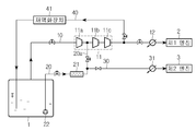
도 1은 본 발명의 실시 예에 따른 연료공급시스템을 나타낸다.
도 2는 본 발명의 실시 예에 따른 연료공급시스템의 변형 예를 나타낸다.1 shows a fuel supply system according to an embodiment of the present invention.
2 shows a modification of the fuel supply system according to the embodiment of the present invention.
이하에서는 본 발명의 실시 예를 첨부 도면을 참조하여 상세히 설명한다. 이하의 실시 예는 본 발명이 속하는 기술분야에서 통상의 지식을 가진 자에게 본 발명의 사상을 충분히 전달하기 위해 제시하는 것이다. 본 발명은 여기서 제시한 실시 예만으로 한정되지 않고 다른 형태로 구체화될 수도 있다. 도면은 본 발명을 명확히 하기 위해 설명과 관계 없는 부분의 도시를 생략하고, 이해를 돕기 위해 구성요소의 크기를 다소 과장하여 표현할 수 있다. Hereinafter, embodiments of the present invention will be described in detail with reference to the accompanying drawings. The following embodiments are provided to fully convey the spirit of the present invention to a person having ordinary skill in the art to which the present invention belongs. The present invention is not limited to the embodiments shown herein but may be embodied in other forms. For the sake of clarity, the drawings are not drawn to scale, and the size of the elements may be slightly exaggerated to facilitate understanding.
본 발명의 실시 예에 따른 연료공급시스템은 도 1에 도시한 바와 같이, 액화가스를 저장하는 저장탱크(1), 저장탱크(1)에서 발생하는 증발가스를 제1엔진(2)의 연료로 공급하는 제1연료공급라인(10), 저장탱크(1)의 액화가스를 기화하여 제1연료공급라인(10)으로 공급해 역시 제1엔진(2)의 연료로 이용할 수 있게 하는 제2연료공급라인(20)을 구비한다. 또 연료공급시스템은 제2연료공급라인(20)의 기화된 증발가스를 제1엔진(2)보다 운용압력이 낮은 제2엔진(3)으로 공급하는 제3연료공급라인(30)을 포함한다.1, a fuel supply system according to an embodiment of the present invention includes a
저장탱크(1)에 저장되는 액화가스는 액화상태로 저장할 수 있는 LNG, LPG, DME(Dimethylether), 에탄(Ethane) 중 어느 하나일 수 있으나 이에 한정되는 것은 아니다. 저장탱크(1)는 단열상태를 유지하면서 연료를 액화상태로 저장하는 탱크다. 예를 들어, 저장탱크(1)는 액화가스가 LNG일 경우 내부압력이 1bar를 유지하거나 연료공급조건을 고려해 그보다 높은 압력으로 유지할 수 있고, 액화상태 유지를 위해 내부온도가 -163도 정도를 유지할 수 있다. The liquefied gas stored in the
제1엔진(2)은 대략 300bar 내외의 연료가스를 공급받아 동작하는 고압가스엔진일 수 있고, 제2엔진(3)은 대략 5 ~ 6bar의 연료가스를 공급받는 저압가스엔진 일 수 있다. 즉 제1엔진(2)의 운용압력(연료가스의 공급압력)이 제2엔진(2)의 운용압력보다 높다. 물론, 엔진들(2,3)은 다양한 방식이 채용될 수 있을 것이므로 엔진의 형태가 이에 한정되는 것은 아니다. 또 본 실시 예는 제1엔진(2)과 제2엔진(2)을 채용한 경우를 제시하고 있으나, 엔진은 하나이거나 복수일 수 있다.The
제1연료공급라인(10)은 저장탱크(1)의 증발가스를 제1엔진(2)으로 공급할 수 있는 배관 등을 포함하며, 여기에는 저장탱크(1)로부터 공급되는 증발가스 압력을 단계적으로 상승시켜 제1엔진(2)의 공급압력을 구현하는 다단 압축기(11)가 설치될 수 있다. 또 제1연료공급라인(10)에는 제1엔진(2)으로 유입되는 연료 온도를 공급조건에 부합하도록 열교환시키는 열교환기(12)가 설치될 수 있다.The first
제2연료공급라인(20)은 저장탱크(1) 내부로부터 연장되어 제1연료공급라인(10)의 다단 압축기(11) 중간 압축단계에 연결될 수 있다. 예를 들어, 다단 압축기(11)는 도 1에 도시한 바와 같이, 단계적인 압력 상승을 위해 제1압축부(11a), 제2압축부(11b), 제3압축부(11c)를 포함할 수 있고, 제2연료공급라인(20)은 제1압축부(11a)와 제2압축부(11b) 사이의 중간 압축단계에 연결될 수 있다. 이는 제2연료공급라인(20)이 제2엔진(3)의 운용압력(대략 5 ~ 6bar)에 해당하는 제1압축부(11a)와 제2압축부(11b) 사이에 연결되도록 하기 위함이다.The second
한편, 제1연료공급라인(10)은 도 2의 예처럼 증발가스를 단계적으로 압축하여 제1엔진(2)의 공급압력을 구현하기 위해 상호 별도로 구성된 제1압축기(61), 제2압축기(62), 제3압축기(63)를 포함할 수 있고, 이들이 배관을 통해 연결될 수 있다. 이러한 경우 제2연료공급라인(20)은 마찬가지로 중간 압축단계인 제1압축기(61)의 하류에 연결될 수 있다.On the other hand, the first
또 제2연료공급라인(20)은 도 1에 도시한 바와 같이, 액화가스를 열교환시키는 열교환기(21)와, 저장탱크(1) 내부의 액화가스를 제2연료공급라인(20)으로 압송하는 압송펌프(22)를 포함한다. 여기서 열교환기(21)는 열원을 이용해 액화가스를 기화시키는 기화기일 수 있다. 1, the second
제3연료공급라인(30)은 제2연료공급라인(20)의 열교환기(21) 하류에서 분기되어 제2엔진(3)으로 연장된다. 따라서 제2연료공급라인(20)의 열교환기(21) 하류 증발가스는 제2엔진(3)의 연료로 공급될 수 있다. The third
제2연료공급라인(20)은 제1연료공급라인(10)과 제3연료공급라인(30)을 연결하는 연결라인(20a)을 포함한다. 즉 제3연료공급라인(30)은 열교환기(21)와 제1연료공급라인(10)을 연결하는 제2연료공급라인(20)의 연결라인(20a)으로부터 분기될 수 있다. 따라서 저장탱크(1)의 증발가스 양이 제1엔진(2) 및 제2엔진(3)의 연료공급량 이상일 경우 제1연료공급라인(10)의 증발가스가 연결라인(20a) 및 제3연료공급라인(30)을 통하여 제2엔진(3)으로 공급될 수 있다. 제3연료공급라인(30)에도 제2엔진(3)으로 유입되는 연료가스 온도를 공급조건에 부합하도록 열교환시키는 열교환기(31)가 설치될 수 있다.The second
제2연료공급라인(20)의 압송펌프(22)는 제2연료공급라인(20) 및 제3연료공급라인(30)의 압력이 제2엔진(3)의 운용압력을 유지할 수 있도록 제2엔진(3)의 운용압력(대략 5 ~ 6bar)으로 저장탱크(1)의 액화가스를 열교환기(21) 쪽으로 압송한다. 또 본 실시 예의 연료공급시스템은 저장탱크(1)에서 발생하는 증발가스의 양이 제1엔진(2) 및 제2엔진(3)의 사용량을 초과할 경우 이를 액화하여 저장탱크(1)로 복귀시키는 재액화라인(40) 및 이 재액화라인(40)에 설치된 재액화장치(41)를 포함할 수 있다. 재액화라인(40)은 제1연료공급라인(10)의 다단 압축기(11) 하류로부터 분기되어 저장탱크(1)로 연장된다.The
다음은 이러한 연료공급시스템의 운용방법에 대하여 설명한다.The following describes how to operate this fuel supply system.
저장탱크(1)의 액화가스 양이 많을 때는 저장탱크(1)에서 자연적으로 발생하는 증발가스 양이 많기 때문에 저장탱크(1)의 증발가스를 제1엔진(2)과 제2엔진(3)의 연료로 이용할 수 있다. 즉 저장탱크(1)의 증발가스 양이 제1엔진(2) 및 제2엔진(3)의 연료공급량 이상일 경우 저장탱크(1)의 증발가스를 연료로 이용한다. When the amount of liquefied gas in the
이 경우에는 저장탱크(1)의 증발가스를 제1연료공급라인(10)의 다단 압축기(11)에서 압축하여 제1엔진(2)으로 공급압력을 상승시킨 후 제1엔진(2)의 연료로 공급한다. 또 이러한 경우에는 다단 압축기(11) 중간압축단계의 증발가스를 제2연료공급라인(20)의 연결라인(20a)과 제3연료공급라인(30)을 통해 제2엔진(3)의 연료로 공급할 수 있다. 이때 제3연료공급라인(30)으로 공급되는 증발가스는 다단 압축기(11)의 중간압축단계에서 분기되므로 제2엔진(3)의 공급압력을 유지할 수 있다.In this case, the evaporative gas of the
저장탱크(1)의 증발가스 발생량이 제1엔진(2)과 제2엔진(3)의 소모량을 초과할 경우에는 제1연료공급라인(10)의 다단 압축기(11) 하류 증발가스를 재액화장치(41)에서 액화하여 다시 저장탱크(1)로 공급할 수 있다.When the evaporation gas generation amount of the
저장탱크(1)에 담긴 액화가스 양이 적어 저장탱크(1)에서 발생하는 증발가스 양이 제1 및 제2엔진(2,3)의 연료공급량 미만일 경우에는 저장탱크(1)의 액화가스를 제2연료공급라인(20)을 통해 제1엔진(2)의 연료로 공급할 수 있다. 이때는 압송펌프(22)가 저장탱크(1)의 액화가스를 열교환기(21)로 압송하면, 액화가스가 열교환기(21)에서 열교환을 통해 기화된 후 다단 압축기(11)의 중간압축단계로 공급된다. 그리고 다단 압축기(11)의 중간단계 이후의 압축을 통해 제1엔진(2)의 공급압력으로 압력이 상승된 후 제1엔진(2)으로 공급된다. 또 이때는 열교환기(21) 하류의 증발가스가 제3연료공급라인(30)을 통해 제2엔진(3)의 연료로 공급될 수 있다.When the amount of the liquefied gas contained in the
한편, 제2엔진(3)을 가동하지 않고 제1엔진(2)만을 가동할 때는 저장탱크(1)의 증발가스 양이 제1엔진(2)의 연료공급량 이상일 경우 저장탱크(1)의 증발가스를 제1연료공급라인(10)을 통해 제1엔진(2)의 연료로 공급할 수 있다. 그리고 저장탱크(1)의 증발가스 양이 제1엔진(2)의 연료공급량 미만일 경우에는 저장탱크(1)의 액화가스를 열교환기(21)에서 기화한 후 제2연료공급라인(20) 및 제1연료공급라인(10)을 통해 제1엔진(2)의 연료로 공급할 수 있다. On the other hand, when only the
이처럼 본 실시 예에 따른 연료공급시스템은 저장탱크(1)에 담긴 액화가스의 양이 많아 자연 발생하는 증발가스 양이 많을 경우 저장탱크의 증발가스를 연료로 이용할 수 있고, 저장탱크(1)에 담긴 액화가스의 양이 적어 자연 발생하는 증발가스 양이 적을 경우 저장탱크(1)의 액화가스를 처리하여 연료로 이용할 수 있다. 따라서 저장탱크(1)의 증발가스 발생량에 무관하게 안정적인 연료공급을 구현할 수 있다.As described above, in the fuel supply system according to the present embodiment, when the amount of liquefied gas contained in the
1: 저장탱크,
2: 제1엔진,
3: 제2엔진,
10: 제1연료공급라인,
11: 다단 압축기,
12: 열교환기,
20: 제2연료공급라인,
21: 열교환기,
22: 압송펌프,
30: 제3연료공급라인,
31: 열교환기,
40: 재액화라인,
41: 재액화장치.1: storage tank, 2: first engine,
3: a second engine, 10: a first fuel supply line,
11: multi-stage compressor, 12: heat exchanger,
20: second fuel supply line, 21: heat exchanger,
22: a pressure feeding pump, 30: a third fuel supply line,
31: heat exchanger, 40: reflux line,
41: Remelting device.
Claims (5)
상기 저장탱크의 증발가스를 제1압축기 및 제2압축기에서 압축하여 제1엔진으로 공급하는 제1연료공급라인; 및
상기 저장탱크의 액화가스를 열교환기에서 열교환하여 상기 제1압축기 하류로 공급하는 제2연료공급라인을 포함하는 연료공급시스템.A storage tank for storing liquefied gas;
A first fuel supply line for compressing the evaporated gas of the storage tank in the first compressor and the second compressor and supplying the compressed gas to the first engine; And
And a second fuel supply line for heat-exchanging the liquefied gas in the storage tank in the heat exchanger and supplying it to the downstream of the first compressor.
상기 제2연료공급라인에서 분기되어, 상기 열교환기 하류의 증발가스를 상기 제1엔진보다 운용압력이 낮은 제2엔진으로 공급하는 제3연료공급라인을 더 포함하는 연료공급시스템.The method according to claim 1,
And a third fuel supply line which branches from the second fuel supply line and supplies the evaporation gas downstream of the heat exchanger to a second engine having a lower operating pressure than the first engine.
상기 제2연료공급라인은 상기 제1연료공급라인과 상기 제3연료공급라인을 연결하는 연결라인을 포함하고,
상기 저장탱크의 증발가스 양이 상기 제1 및 제2엔진의 연료공급량 이상일 경우, 상기 저장탱크의 증발가스만을 이용하여 상기 제1연료공급라인을 통해 상기 제1엔진으로, 상기 연결라인 및 상기 제3연료공급라인을 통해 상기 제2엔진으로 상기 저장탱크의 증발가스를 공급하고, 상기 저장탱크의 액화가스 공급을 차단하는 연료공급시스템.3. The method of claim 2,
The second fuel supply line includes a connection line connecting the first fuel supply line and the third fuel supply line,
Wherein the first engine is connected to the first engine via the first fuel supply line only by the evaporation gas of the storage tank when the amount of evaporation gas in the storage tank is equal to or greater than the fuel supply amount of the first and second engines, 3 fuel supply line to supply the evaporation gas of the storage tank to the second engine, and to shut off the supply of liquefied gas to the storage tank.
상기 저장탱크의 증발가스 양이 상기 제1 및 제2엔진의 연료공급량 미만일 경우, 상기 저장탱크의 액화가스를 상기 제2연료공급라인을 통해 상기 제1엔진으로 공급하고, 상기 제3연료공급라인을 통해 제2엔진으로 공급하는 연료공급시스템.3. The method of claim 2,
Supplying the liquefied gas of the storage tank to the first engine through the second fuel supply line when the amount of evaporation gas in the storage tank is less than the fuel supply amount of the first and second engines, To the second engine.
상기 저장탱크의 증발가스 양이 상기 제1엔진의 연료공급량 미만일 경우, 상기 제2연료공급라인을 통해 상기 액화가스를 상기 제1엔진으로 공급하는 연료공급시스템.
The method according to claim 1,
And supplies the liquefied gas to the first engine via the second fuel supply line when the amount of evaporated gas in the storage tank is less than the fuel supply amount of the first engine.
Priority Applications (1)
| Application Number | Priority Date | Filing Date | Title |
|---|---|---|---|
| KR1020140185953A KR102189772B1 (en) | 2014-12-22 | 2014-12-22 | Fuel supply system |
Applications Claiming Priority (1)
| Application Number | Priority Date | Filing Date | Title |
|---|---|---|---|
| KR1020140185953A KR102189772B1 (en) | 2014-12-22 | 2014-12-22 | Fuel supply system |
Publications (2)
| Publication Number | Publication Date |
|---|---|
| KR20160077277A true KR20160077277A (en) | 2016-07-04 |
| KR102189772B1 KR102189772B1 (en) | 2020-12-14 |
Family
ID=56500752
Family Applications (1)
| Application Number | Title | Priority Date | Filing Date |
|---|---|---|---|
| KR1020140185953A Active KR102189772B1 (en) | 2014-12-22 | 2014-12-22 | Fuel supply system |
Country Status (1)
| Country | Link |
|---|---|
| KR (1) | KR102189772B1 (en) |
Cited By (2)
| Publication number | Priority date | Publication date | Assignee | Title |
|---|---|---|---|---|
| US20230032594A1 (en) * | 2019-11-20 | 2023-02-02 | Gaztransport Et Technigaz | System for supplying gas to at least one gas-consuming appliance equipping a ship |
| KR20230146073A (en) * | 2021-03-31 | 2023-10-18 | 미츠비시 조우센 가부시키가이샤 | Ship |
Citations (2)
| Publication number | Priority date | Publication date | Assignee | Title |
|---|---|---|---|---|
| KR101333932B1 (en) * | 2013-04-24 | 2013-11-27 | 현대중공업 주식회사 | A treatment system of liquefied natural gas |
| KR20140138015A (en) * | 2013-05-23 | 2014-12-03 | 대우조선해양 주식회사 | Hybrid fuel supply system for a ship engine |
-
2014
- 2014-12-22 KR KR1020140185953A patent/KR102189772B1/en active Active
Patent Citations (2)
| Publication number | Priority date | Publication date | Assignee | Title |
|---|---|---|---|---|
| KR101333932B1 (en) * | 2013-04-24 | 2013-11-27 | 현대중공업 주식회사 | A treatment system of liquefied natural gas |
| KR20140138015A (en) * | 2013-05-23 | 2014-12-03 | 대우조선해양 주식회사 | Hybrid fuel supply system for a ship engine |
Cited By (4)
| Publication number | Priority date | Publication date | Assignee | Title |
|---|---|---|---|---|
| US20230032594A1 (en) * | 2019-11-20 | 2023-02-02 | Gaztransport Et Technigaz | System for supplying gas to at least one gas-consuming appliance equipping a ship |
| US12560136B2 (en) * | 2019-11-20 | 2026-02-24 | Gaztransport Et Technigaz | System for supplying gas to at least one gas-consuming appliance equipping a ship |
| KR20230146073A (en) * | 2021-03-31 | 2023-10-18 | 미츠비시 조우센 가부시키가이샤 | Ship |
| CN117098705A (en) * | 2021-03-31 | 2023-11-21 | 三菱造船株式会社 | ship |
Also Published As
| Publication number | Publication date |
|---|---|
| KR102189772B1 (en) | 2020-12-14 |
Similar Documents
| Publication | Publication Date | Title |
|---|---|---|
| KR101711997B1 (en) | Fuel supply system | |
| KR101644386B1 (en) | Fuel gas supplying system in ships | |
| KR102189792B1 (en) | Reliquefaction system of liquified fuel propulsion ship | |
| KR101380427B1 (en) | A treatment system of liquefied gas | |
| KR102260378B1 (en) | Fuel gas supplying system in ships | |
| KR101711955B1 (en) | Fuel gas supplying system in ships | |
| KR20160074983A (en) | Fuel gas supplying system in ships | |
| KR20160099211A (en) | Fuel gas supplying system in ships | |
| KR101661929B1 (en) | Fuel gas supplying system in ships | |
| KR20150101619A (en) | System for supplying fuel gas in ships | |
| KR101722369B1 (en) | Fuel gas supplying system in ships | |
| KR102189743B1 (en) | Fuel gas supply system and method for ship | |
| KR20160077277A (en) | Fuel supply system | |
| KR101623098B1 (en) | Fuel Supply System And Method For Ship Or Offshore Platform | |
| KR101884828B1 (en) | System for supplying fuel gas in ships | |
| KR102189782B1 (en) | Fuel supply system of liquefied gas carrier | |
| KR101701724B1 (en) | Fuel gas supplying system in ships | |
| KR102285470B1 (en) | Fuel gas supply system | |
| KR20160113404A (en) | Fuel gas supplying system in ships | |
| KR20160137895A (en) | Fuel gas supplying system in ships | |
| KR20160074170A (en) | Fuel gas supplying system in ships | |
| KR101672196B1 (en) | Fuel gas supplying system in ships | |
| KR101722368B1 (en) | Fuel gas supplying system in ships | |
| KR101498388B1 (en) | A Liquefied Gas Treatment System | |
| KR102053479B1 (en) | Treatment system of liquefied gas |
Legal Events
| Date | Code | Title | Description |
|---|---|---|---|
| PA0109 | Patent application |
Patent event code: PA01091R01D Comment text: Patent Application Patent event date: 20141222 |
|
| PG1501 | Laying open of application | ||
| A201 | Request for examination | ||
| PA0201 | Request for examination |
Patent event code: PA02012R01D Patent event date: 20190725 Comment text: Request for Examination of Application Patent event code: PA02011R01I Patent event date: 20141222 Comment text: Patent Application |
|
| E902 | Notification of reason for refusal | ||
| PE0902 | Notice of grounds for rejection |
Comment text: Notification of reason for refusal Patent event date: 20200521 Patent event code: PE09021S01D |
|
| E701 | Decision to grant or registration of patent right | ||
| PE0701 | Decision of registration |
Patent event code: PE07011S01D Comment text: Decision to Grant Registration Patent event date: 20201023 |
|
| GRNT | Written decision to grant | ||
| PR0701 | Registration of establishment |
Comment text: Registration of Establishment Patent event date: 20201204 Patent event code: PR07011E01D |
|
| PR1002 | Payment of registration fee |
Payment date: 20201207 End annual number: 3 Start annual number: 1 |
|
| PG1601 | Publication of registration | ||
| PR1001 | Payment of annual fee |
Payment date: 20231129 Start annual number: 4 End annual number: 4 |