KR20160077307A - Sliding safety cutter - Google Patents
Sliding safety cutter Download PDFInfo
- Publication number
- KR20160077307A KR20160077307A KR1020140186137A KR20140186137A KR20160077307A KR 20160077307 A KR20160077307 A KR 20160077307A KR 1020140186137 A KR1020140186137 A KR 1020140186137A KR 20140186137 A KR20140186137 A KR 20140186137A KR 20160077307 A KR20160077307 A KR 20160077307A
- Authority
- KR
- South Korea
- Prior art keywords
- main body
- blade
- rotating member
- roller
- slit
- Prior art date
- Legal status (The legal status is an assumption and is not a legal conclusion. Google has not performed a legal analysis and makes no representation as to the accuracy of the status listed.)
- Abandoned
Links
Images




Classifications
-
- B—PERFORMING OPERATIONS; TRANSPORTING
- B26—HAND CUTTING TOOLS; CUTTING; SEVERING
- B26B—HAND-HELD CUTTING TOOLS NOT OTHERWISE PROVIDED FOR
- B26B5/00—Hand knives with one or more detachable blades
-
- B—PERFORMING OPERATIONS; TRANSPORTING
- B26—HAND CUTTING TOOLS; CUTTING; SEVERING
- B26B—HAND-HELD CUTTING TOOLS NOT OTHERWISE PROVIDED FOR
- B26B29/00—Guards or sheaths or guides for hand cutting tools; Arrangements for guiding hand cutting tools
- B26B29/02—Guards or sheaths for knives
-
- B—PERFORMING OPERATIONS; TRANSPORTING
- B26—HAND CUTTING TOOLS; CUTTING; SEVERING
- B26B—HAND-HELD CUTTING TOOLS NOT OTHERWISE PROVIDED FOR
- B26B3/00—Hand knives with fixed blades
Landscapes
- Life Sciences & Earth Sciences (AREA)
- Forests & Forestry (AREA)
- Engineering & Computer Science (AREA)
- Mechanical Engineering (AREA)
- Knives (AREA)
Abstract
본 발명의 슬라이딩 안전커터는, 칼날이 설치된 본체; 상기 본체에 설치되어 칼날의 절단 방향을 안내하도록 직선으로 구르는 롤러; 및 상기 본체에 설치되며 탄성변형에 의해서만 칼날을 노출시키는 탄성부재;를포함하는 것을 특징으로 한다.
이에 따라, 롤러의 직선방향 구름에 의해 자와 같은 도구의 사용없이 절단대상물을 직선으로 자를 수 있는 효과가 있다.A sliding safety cutter of the present invention includes: a main body having a blade; A roller installed on the main body and rolling in a straight line so as to guide the cutting direction of the blade; And an elastic member installed in the main body and exposing the blade only by elastic deformation.
Accordingly, there is an effect that the object to be cut can be cut linearly without the use of a tool such as a ruler by the roller in the linear direction.
Description
본 발명은 슬라이딩 안전커터에 관한 것으로, 더욱 상세하게는 자를 사용하지 않으면서도 절단대상물을 직선으로 자를 수 있는 슬라이딩 안전커터에 관한 것이다.
BACKGROUND OF THE INVENTION 1. Field of the Invention The present invention relates to a sliding safety cutter, and more particularly, to a sliding safety cutter capable of linearly cutting an object to be cut without using a ruler.
일반적으로 칼로 종이와 같은 절단대상물을 직선으로 자르기 위해서는 자를절단대상물 위에 얹혀놓고 자의 측면을 따라 칼날을 이동시켜 절단대상물을 자르게 된다.In general, in order to straighten a cutting object such as a paper with a knife, the cutting object is cut by placing the cutting object on the cutting object and moving the blade along the side of the cutting object.
이와 같은 방법은 사용자가 절단대상물을 자르는 동안 자의 측면을 따라 이동하는 칼날의 각도를 일정하게 유지하기가 어렵게 된다.Such a method makes it difficult to keep the angle of the blade moving along the side of the person constant while the user cuts the object to be cut.
이 경우, 플라스틱이 대부분인 자의 측면을 상하게 함과 동시에 사용자의 부주의로 칼날이 자의 측면을 타고 자의 상부면으로 이동하여 사용자의 손이 칼날에 의해 손상되는 일이 자주 발생한다.In this case, the side of most of the plastic is hurt, and at the same time, the user often accidentally moves the blade to the upper surface of the rider's side and the user's hand is often damaged by the blade.
특히 사용자가 어린이의 경우 사용 미숙으로 손을 다칠 우려가 더욱 높아진다.Especially, when the user is a child, the risk of injuring his / her hand by immaturity is further increased.
이와 같은 문제점을 개선하기 위해 하기 특허문헌 1(이하, '종래기술 1')의 "이동식 절단용 칼을 부착한 자"가 개발되었다.In order to solve such a problem, a "person with a movable cutting knife" of Patent Document 1 (hereinafter referred to as "Prior Art 1") has been developed.
도 1에 도시한 바와 같이, 종래기술 1의 이동식 절단용 칼을 부착한 자는, 자(2)와, 누룸판(6) 및 칼날(7)로 구성된다.As shown in Fig. 1, a person to which the movable cutting knife of the prior art 1 is attached is composed of the
상기 자(2)에는 레일 역할을 하는 두 개의 홈(1)이 형성되며, 상기 누룸판(6)에는 홈(1)에 끼워지는 요철부분(3)이 형성된다.Two grooves (1) serving as a rail are formed on the base (2), and the base plate (6) is provided with a protruding and recessed portion (3) fitted in the groove (1).
상기 누룸판(6)에는 탄성지지대(4) 및 칼집부분(5)이 형성된다.The resilient support 4 and the sheath 5 are formed on the pusher plate 6.
이에 따라, 상기 누룸판(6)은 자(2)의 홈(1)을 따라 이동하며 절단대상물을 직선으로 자르게 된다.Accordingly, the pusher plate 6 moves along the groove 1 of the
그러나, 종래기술 1의 이동식 절단용 칼을 부착한 자의 경우에는 자에 레일 역할을 하는 홈을 형성해야 할 뿐만 아니라 칼날을 포함하는 누룸판도 별도 구비되어 있어 제조비용이 높은 문제점이 있었다.However, in the case of the person having the movable cutting knife of the prior art 1, not only a groove serving as a rail is formed but also a slip plate including a blade is additionally provided, resulting in a high manufacturing cost.
뿐만 아니라, 칼날이 외부 노출된 상태를 유지하여 안전사고가 발생하게 된다.In addition, a safety accident is generated by keeping the blade exposed to the outside.
이와 같은 문제점을 개선하기 위해 본 발명의 출원인은 하기 특허문헌 2(이하, '종래기술 2')의 "탄성 칼날돌출식 안전커터"를 개발하였다.In order to solve such a problem, the applicant of the present invention has developed a "safety cutter with an elastic blade protrusion" of the following Patent Document 2 (hereinafter referred to as "
도 2에 도시한 바와 같이, 종래기술 2의 탄성 칼날 돌출식 안전커터(100)는, 본체(110a)를 절단대상물(3) 상에 위치시킨 상태에서 하부방향으로 가압하는 경우에만 칼날이 돌출되도록 구성된다.As shown in Fig. 2, the
구체적으로, 본체(110a)에 형성된 슬릿(111)과 탄성지지부(113)에 의해 가압시에만 칼날이 돌출되어 안전사고의 위험없이 누구나 안전하게 사용할 수 있게 된다.Specifically, the
그러나, 종래기술 2의 안전커터는 절단대상물을 직선으로 자르기 위해선 자가 필요했다.However, the safety cutter of Prior
따라서, 자를 사용하지 않으면서도 절단대상물을 직선을 자를 수 있음과 동시에 안전사고를 방지하는 개선된 형태의 안전커터의 개발이 요구되고 있는 실정이다.
Accordingly, there is a need to develop an improved safety cutter that can cut a straight line without cutting the object and prevent a safety accident.
본 발명은 전술한 종래의 제반 문제점을 해결하기 위하여 안출된 것으로, 본 발명의 목적은 자와 같은 도구의 사용없이 절단대상물을 직선으로 자를 수 있는 슬라이딩 안전커터를 제공하는데 있다.SUMMARY OF THE INVENTION It is an object of the present invention to provide a sliding safety cutter in which a cutting object can be linearly cut without using a tool such as a ruler.
본 발명의 다른 목적은 사용시에만 칼날이 노출되어 안전사고를 예방할 수 있는 슬라이딩 안전커터를 제공하는데 있다.
Another object of the present invention is to provide a sliding safety cutter in which a blade is exposed only during use to prevent a safety accident.
상기와 같은 목적을 달성하기 위한 본 발명의 슬라이딩 안전커터는, 칼날이 설치된 본체; 상기 본체에 설치되어 칼날의 절단 방향을 안내하도록 직선으로 구르는 롤러; 및 상기 본체에 설치되며 탄성변형에 의해서만 칼날을 노출시키는 탄성부재;를포함하는 것을 특징으로 한다.According to an aspect of the present invention, there is provided a sliding safety cutter including: a main body having a blade; A roller installed on the main body and rolling in a straight line so as to guide the cutting direction of the blade; And an elastic member installed in the main body and exposing the blade only by elastic deformation.
또한, 상기 본체에 대해 힌지 결합된 회전부재가 더 구비되며, 상기 회전부재에는 상기 롤러가 설치된 것을 특징으로 한다.Further, a rotating member hinged to the main body is further provided, and the roller is installed on the rotating member.
또한, 상기 회전부재는 본체와 결합되는 회전체와 상기 롤러가 설치되는 헤드로 구성된 것을 특징으로 한다.The rotating member may include a rotating body coupled to the main body and a head provided with the roller.
또한, 상기 본체에는 힌지축이 형성되며, 상기 회전체에는 힌지축과 결합되는 힌지공이 형성된 것을 특징으로 한다.The main body is formed with a hinge shaft, and the rotating body is formed with a hinge hole coupled with the hinge shaft.
또한, 상기 본체에는 회전부재가 설치되는 수용홈이 형성된 것을 특징으로 한다.In addition, the main body is formed with a receiving groove in which a rotating member is installed.
또한, 상기 수용홈에는 회전부재가 접히는 위치를 지지하는 제1스토퍼와 및 회전부재가 펼쳐지는 위치를 지지하는 제2스토퍼가 형성된 것을 특징으로 한다.The receiving groove may have a first stopper for supporting a position where the rotating member is folded, and a second stopper for supporting a position where the rotating member is extended.
또한, 상기 헤드에는 회전부재가 접히는 위치에서 본체와 맞닿아 지지하는 제3스토퍼와, 회전부재가 펼쳐지는 위치에서 본체의 맞닿아 지지하는 제4스토퍼가 형성된 것을 특징으로 한다.The head is further provided with a third stopper which abuts against the main body at a position where the rotating member is folded, and a fourth stopper which abuts against the main body at a position where the rotating member is deployed.
또한, 상기 탄성부재에는 'U'자형이며 일단은 개방된 제1슬릿과 상기 제1슬릿의 개방단에서 하측으로 연장형성된 제2슬릿 및 상기 제2슬릿에 의해 분할되는 탄성변형단이 형성된 것을 특징으로 한다.The elastic member may include a U-shaped first slit having an open end, a second slit extending downward from an open end of the first slit, and an elastically deformable end divided by the second slit. .
또한, 상기 탄성변형단에는 라운딩부가 형성된 것을 특징으로 한다.Further, the elastic deforming end is characterized in that a rounded portion is formed.
또한, 상기 탄성변형단에는 반원형의 제3슬릿이 형성된 것을 특징으로 한다.Further, the elastically deformed end is characterized by a third slit having a semicircular shape.
또한, 상기 본체에는 탄성부재와 칼날이 돌출되도록 개방단이 형성된 것을 특징으로 한다.Further, the main body is characterized in that an open end is formed so that the elastic member and the blade are protruded.
또한, 상기 칼날을 본체에 고정시키며 고정돌기가 형성된 홀더가 더 구비되며, 상기 본체에는 고정돌기가 이동하는 슬라이딩홈이 형성된 것을 특징으로 한다.
The main body further includes a holder having a fixing protrusion formed by fixing the blade to the main body, and a sliding groove through which the fixing protrusion moves is formed in the main body.
본 발명에 따른 슬라이딩 안전커터에 따르면, 롤러의 직선방향 구름에 의해 자와 같은 도구의 사용없이 절단대상물을 직선으로 자를 수 있는 효과가 있다.According to the sliding safety cutter of the present invention, there is an effect that the object to be cut can be linearly cut without the use of a tool such as a ruler by the roller in the linear direction.
또한, 탄성부재에 의해 안저커터를 사용시에만 칼날이 노출되어 안전사고를 예방할 수 있게 된다.Further, the blade is exposed only when the fundus cutter is used by the elastic member, so that a safety accident can be prevented.
또한, 롤러가 설치된 회전부재는 본체에 대해 접이되어 휴대성이 향상된다.
Further, the rotating member provided with the roller is folded with respect to the main body, thereby improving the portability.
도 1은 종래기술 1의 커터를 도시한 단면도이다.
도 2는 종래기술 2의 안전커터를 도시한 도면이다.
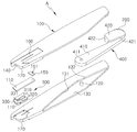
도 3은 본 발명에 따른 슬라이딩 안전커터를 분해 도시한 사시도이다.
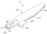
도 4는 도 3의 결합상태를 도시한 사시도이다.
도 5는 본 발명에 따른 롤러의 사용상태를 도시한 사시도이다.
도 6은 본 발명에 따른 슬라이딩 안전커터의 칼날이 돌출되는 것을 도시한 사용 상태도이다.1 is a cross-sectional view showing a cutter of the conventional art 1;
2 is a view showing a safety cutter of the
3 is a perspective view illustrating an exploded view of the sliding safety cutter according to the present invention.
FIG. 4 is a perspective view showing the coupled state of FIG. 3; FIG.
5 is a perspective view showing the use state of the roller according to the present invention.
FIG. 6 is a view illustrating a state in which the blade of the sliding safety cutter according to the present invention protrudes. FIG.
이하, 본 발명의 바람직한 실시 예를 첨부된 도면을 참조하여 상세하게 설명한다.Hereinafter, preferred embodiments of the present invention will be described in detail with reference to the accompanying drawings.
도 3은 본 발명에 따른 슬라이딩 안전커터를 분해 도시한 사시도이고, 도 4는 도 3의 결합상태를 도시한 사시도이며, 도 5는 본 발명에 따른 롤러의 사용상태를 도시한 사시도이고, 도 6은 본 발명에 따른 슬라이딩 안전커터의 칼날이 돌출되는 것을 도시한 사용 상태도이다.FIG. 3 is a perspective view illustrating an exploded perspective view of the sliding safety cutter according to the present invention, FIG. 4 is a perspective view illustrating a combined state of FIG. 3, FIG. 5 is a perspective view showing a state of use of the roller according to the present invention, Is a view illustrating a state in which the blade of the sliding safety cutter according to the present invention protrudes.
도 3 내지 도 6에 도시한 바와 같이, 본 발명에 따른 슬라이딩 안전커터(A)는, 칼날(110)이 설치된 본체(100)와, 상기 본체(100)에 설치되어 칼날(110)의 절단 방향을 안내하도록 직선으로 구르는 롤러(200) 및 상기 본체(100)에 설치되며 탄성변형에 의해서만 칼날(110)을 노출시키는 탄성부재(300)로 구성된다.3 to 6, a sliding safety cutter A according to the present invention includes a
상기 본체(100)는 사용자가 파지하도록 막대형태로 형성되며, 상기 본체(100)의 일측 단부로 칼날(110)이 설치된다. 다만 상기 칼날(110)은 탄성부재(300)에 의해 외부로 노출되지 않은 상태를 유지하여 안전사고를 예방하게 된다.The
상기 롤러(200)는 구름면이 편평한 형태를 가지며 절단대상물과 밀착되어 좌우로 흔들리지 않으며 구르게 된다.The
이에 따라, 롤러(200)의 직선방향 구름에 의해 자와 같은 도구의 사용없이 절단대상물을 직선으로 자를 수 있게 된다.Thus, the linear rolling of the
롤러(200)의 구름면에는 절단대상물과의 마찰력을 높이기 위해 널링 가공에 의한 홈이 형성되거나, 고무가 설치될 수도 있다. A groove may be formed on the rolling surface of the
상기 탄성부재(300)는 본체(100)에 칼날(110)과 겹쳐짐과 동시에 칼날(110)보다 절단대상물의 방향으로 돌출되도록 설치되며, 사용자가 본체(100)를 파지한 상태로 탄성부재(300)에 힘을 가하는 경우에만 탄성부재(110)는 변형되어 칼날(110)을 노출된다.
The
상기 본체(100)에 대해 힌지 결합된 회전부재(400)가 더 구비되며, 상기 회전부재(400)에는 상기 롤러(200)가 설치된다.The
또한, 상기 회전부재(400)는 본체(100)와 결합되는 회전체(410)와 상기 롤러(200)가 설치되는 헤드(420)로 구성된다.The rotating
그리고, 상기 본체(100)에는 힌지축(120)이 형성되며, 상기 회전체(410)에는 힌지축(120)과 결합되는 힌지공(411)이 형성된다. A
이에 따라, 롤러(110)를 포함한 회전부재(400)는 본체(100)에 대해 접이되거나 펼쳐지게 된다. 즉, 롤러(110)가 설치된 회전부재(400)는 본체(100)에 대해 접이되어 휴대성이 향상된다. Accordingly, the rotating
뿐만 아니라, 롤러(110)의 선택적인 사용이 가능함에 따라 절단대상물을 직선부터 자유곡선까지 모두 절단할 수 있게 된다.In addition, since the
한편, 상기 본체(100)에는 회전부재(400)가 설치되는 수용홈(130)이 형성된다. 즉, 회전부재(400)의 일부가 수용홈(130)의 내부로 수용되며 펼쳐지거나 접이되어 안전커터(A)의 전체적인 크기를 줄여주게 된다.Meanwhile, the
또한, 상기 수용홈(130)에는 회전부재(400)가 접히는 위치를 지지하는 제1스토퍼(131)와 및 회전부재(400)가 펼쳐지는 위치를 지지하는 제2스토퍼(132)가 형성되어 회전부재(400)의 회전범위를 물리적으로 제한하게 된다.A
그리고, 상기 헤드(420)에는 회전부재(400)가 접히는 위치에서 본체(100)의 측면과 맞닿아 지지하는 제3스토퍼(421)와, 회전부재(400)가 펼쳐지는 위치에서 본체(100)의 칼날(110)이 설치되지 않은 타측 단부와 맞닿아 지지하는 제4스토퍼(422)가 형성된다. 상기 제3,4스토퍼(421,422)에 의해 회전부재(400)의 회전범위를 물리적으로 제한하게 된다.
The
상기 탄성부재(300)에는 'U'자형이며 일단은 개방된 제1슬릿(310)과 상기 제1슬릿(310)의 개방단에서 하측으로 연장형성된 제2슬릿(320) 및 상기 제2슬릿(320)에 의해 분할되는 탄성변형단(330)이 형성된다.The
또한, 상기 탄성변형단(330)에는 라운딩부(331)가 형성되어 절단대상물을 손상시키기는 것을 억제함과 동시에 절단대상물과의 간섭을 최대한 억제하게 된다.In addition, a
그리고, 상기 탄성변형단(330)에는 반원형의 제3슬릿(340)이 형성된다. 상기 제3슬릿(340)이 형성된 위치는 탄성변형단(330)에서 제일 얇아지게 됨에 따라 사용자가 힘을 가하게 되면 쉽게 변형이 이루어지게 된다.In addition, a semicircular
탄성부재(300)에 힘이 가해지면, 제2슬릿(320)의 사이가 줄어들며 탄성변형단(330)은 변형되며, 그 후 제1슬릿(310)의 사이가 줄어들며 칼날(110)이 노출된다.When a force is applied to the
즉, 도 6과 같이 칼날(110)과 탄성부재(300)를 절단대상물 상에 위치시킨 상태에서 하부방향으로 가압하는 경우에만 칼날(110)이 노출되어 안전사고를 예방할 수 있게 된다.That is, as shown in FIG. 6, the
한편, 상기 제1슬릿(310)과 제2슬릿(320)의 사이의 부재에는 탄성돌기(350)가 더 형성되어 있어 탄성변형단(330)의 변형이 제1슬릿(310)으로 전달된다.
The
상기 본체(100)에는 탄성부재(300)와 칼날(110)이 돌출되도록 개방단(140)이 형성된다.The
또한, 상기 본체(100)에는 슬라이딩면(170)이 형성되어 있어 절단대상물 상부를 미끄러지듯 이동이 가능하게 된다. 즉 절단대상물과 본체(100)를 밀착시켜 직선 절단시에 본체(100)의 수직방향의 움직임을 억제해주게 된다.
In addition, the
상기 칼날(110)을 본체(100)에 고정시키며 고정돌기(151)가 형성된 홀더(150)가 더 구비되며, 상기 본체(100)에는 고정돌기(151)가 이동하는 슬라이딩홈(160)이 형성된다. 따라서, 고정돌기(151)를 슬라이딩홈(160)에서 이동하여 칼날(110)을 개방단(140)으로 노출시켜 날을 자르거나 교체 사용할 수 있게 된다.
The
본 발명에 따르면, 롤러(200)의 직선방향 구름에 의해 도구의 사용없이 절단대상물을 직선으로 자를 수 있으며, 탄성부재(300)에 의해 안전커터를 사용시에만 칼날이 노출되어 안전사고를 예방할 수 있으며, 롤러(200)가 설치된 회전부재(400)는 본체(100)에 대해 접이되어 휴대성이 향상된다.
According to the present invention, the object to be cut can be linearly cut without the use of a tool by the linear roll of the
이상, 본 발명의 바람직한 실시 예에 대하여 상세히 설명하였으나, 본 발명의 기술적 범위는 전술한 실시 예에 한정되지 않고 특허청구범위에 의하여 해석되어야 할 것이다. 이때, 이 기술분야에서 통상의 지식을 습득한 자라면, 본 발명의 범위에서 벗어나지 않으면서도 많은 수정과 변형이 가능함을 고려해야 할 것이다.
Although the preferred embodiments of the present invention have been described in detail, the technical scope of the present invention is not limited to the above-described embodiments, but should be construed according to the claims. It will be understood by those skilled in the art that many modifications and variations are possible without departing from the scope of the present invention.
A - 안전커터
100 - 본체
110 - 칼날
200 - 롤러
300 - 탄성부재
400 - 회전부재A - Safety cutter 100 - Body
110 - Blade 200 - Rollers
300 - Elastic member 400 - Rotating member
Claims (12)
상기 본체에 설치되어 칼날의 절단 방향을 안내하도록 직선으로 구르는 롤러; 및
상기 본체에 설치되며 탄성변형에 의해서만 칼날을 노출시키는 탄성부재;를포함하는 것을 특징으로 하는 슬라이딩 안전커터.
A body with a blade;
A roller installed on the main body and rolling in a straight line so as to guide the cutting direction of the blade; And
And an elastic member installed in the main body and exposing the blade only by elastic deformation.
상기 본체에 대해 힌지 결합된 회전부재가 더 구비되며, 상기 회전부재에는 상기 롤러가 설치된 것을 특징으로 하는 슬라이딩 안전커터
The method according to claim 1,
Further comprising a rotating member hinged to the main body, wherein the rotating member is provided with the roller,
상기 회전부재는 본체와 결합되는 회전체와 상기 롤러가 설치되는 헤드로 구성된 것을 특징으로 하는 슬라이딩 안전커터.
3. The method of claim 2,
Wherein the rotary member comprises a rotating body coupled to the main body and a head on which the roller is installed.
상기 본체에는 힌지축이 형성되며, 상기 회전체에는 힌지축과 결합되는 힌지공이 형성된 것을 특징으로 하는 슬라이딩 안전커터.
The method of claim 3,
Wherein a hinge shaft is formed in the main body, and a hinge hole is formed in the rotating body so as to be coupled to the hinge shaft.
상기 본체에는 회전부재가 설치되는 수용홈이 형성된 것을 특징으로 슬라이딩 안전커터.
The method of claim 3,
Wherein the main body is formed with a receiving groove in which a rotating member is installed.
상기 수용홈에는 회전부재가 접히는 위치를 지지하는 제1스토퍼와 및 회전부재가 펼쳐지는 위치를 지지하는 제2스토퍼가 형성된 것을 특징으로 하는 슬라이딩 안전커터.
6. The method of claim 5,
Wherein the receiving recess has a first stopper for supporting a position where the rotating member is folded and a second stopper for supporting a position where the rotating member is extended.
상기 헤드에는 회전부재가 접히는 위치에서 본체와 맞닿아 지지하는 제3스토퍼와, 회전부재가 펼쳐지는 위치에서 본체의 맞닿아 지지하는 제4스토퍼가 형성된 것을 특징으로 하는 슬라이딩 안전커터.
The method of claim 3,
Wherein the head is formed with a third stopper which abuts against and supports the main body at a position where the rotating member is folded, and a fourth stopper which abuts against the main body at a position where the rotating member is deployed.
상기 탄성부재에는 'U'자형이며 일단은 개방된 제1슬릿과 상기 제1슬릿의 개방단에서 하측으로 연장형성된 제2슬릿 및 상기 제2슬릿에 의해 분할되는 탄성변형단이 형성된 것을 특징으로 하는 슬라이딩 안전커터.
The method according to claim 1,
Wherein the elastic member is formed with a U-shaped first slit having an open end, a second slit extending downward from an open end of the first slit, and an elastically deformable end divided by the second slit Sliding safety cutter.
상기 탄성변형단에는 라운딩부가 형성된 것을 특징으로 하는 슬라이딩 안전커터.
9. The method of claim 8,
And a rounded portion is formed on the resiliently deformed end.
상기 탄성변형단에는 반원형의 제3슬릿이 형성된 것을 특징으로 하는 슬라이딩 안전커터.
9. The method of claim 8,
And a third slit having a semicircular shape is formed at the resiliently deformed end.
상기 본체에는 탄성부재와 칼날이 돌출되도록 개방단이 형성된 것을 특징으로 하는 슬라이딩 안전커터.
The method according to claim 1,
Wherein the main body is formed with an open end such that the elastic member and the blade are protruded.
상기 칼날을 본체에 고정시키며 고정돌기가 형성된 홀더가 더 구비되며, 상기 본체에는 고정돌기가 이동하는 슬라이딩홈이 형성된 것을 특징으로 하는 슬라이딩 안전커터.
The method according to claim 1,
Further comprising a holder having a fixing protrusion formed by fixing the blade to the main body, and a sliding groove through which the fixing protrusion moves is formed in the main body.
Priority Applications (2)
| Application Number | Priority Date | Filing Date | Title |
|---|---|---|---|
| KR1020140186137A KR20160077307A (en) | 2014-12-22 | 2014-12-22 | Sliding safety cutter |
| PCT/KR2014/013097 WO2016104855A1 (en) | 2014-12-22 | 2014-12-31 | Sliding safety cutter |
Applications Claiming Priority (1)
| Application Number | Priority Date | Filing Date | Title |
|---|---|---|---|
| KR1020140186137A KR20160077307A (en) | 2014-12-22 | 2014-12-22 | Sliding safety cutter |
Publications (1)
| Publication Number | Publication Date |
|---|---|
| KR20160077307A true KR20160077307A (en) | 2016-07-04 |
Family
ID=56150859
Family Applications (1)
| Application Number | Title | Priority Date | Filing Date |
|---|---|---|---|
| KR1020140186137A Abandoned KR20160077307A (en) | 2014-12-22 | 2014-12-22 | Sliding safety cutter |
Country Status (2)
| Country | Link |
|---|---|
| KR (1) | KR20160077307A (en) |
| WO (1) | WO2016104855A1 (en) |
Citations (2)
| Publication number | Priority date | Publication date | Assignee | Title |
|---|---|---|---|---|
| KR0177025B1 (en) | 1996-08-28 | 1999-05-15 | 조대현 | High voltage generator using piezoelectric ceramics |
| KR20130074916A (en) | 2011-12-27 | 2013-07-05 | 오상근 | Safe cutter which blade is protruded elastically of |
Family Cites Families (4)
| Publication number | Priority date | Publication date | Assignee | Title |
|---|---|---|---|---|
| JP2942920B2 (en) * | 1996-11-26 | 1999-08-30 | ヤマタ産業有限会社 | Hand held cutter tool |
| KR200215601Y1 (en) * | 2000-10-10 | 2001-03-15 | 정길호 | A knife comprising a roller |
| JP2007037956A (en) * | 2005-08-04 | 2007-02-15 | Masao Utagawa | Cutter knife |
| AT504384B1 (en) * | 2006-10-16 | 2011-12-15 | Victorinox Ag | POCKET TOOL, ESPECIALLY POCKETKNIVES |
-
2014
- 2014-12-22 KR KR1020140186137A patent/KR20160077307A/en not_active Abandoned
- 2014-12-31 WO PCT/KR2014/013097 patent/WO2016104855A1/en not_active Ceased
Patent Citations (2)
| Publication number | Priority date | Publication date | Assignee | Title |
|---|---|---|---|---|
| KR0177025B1 (en) | 1996-08-28 | 1999-05-15 | 조대현 | High voltage generator using piezoelectric ceramics |
| KR20130074916A (en) | 2011-12-27 | 2013-07-05 | 오상근 | Safe cutter which blade is protruded elastically of |
Also Published As
| Publication number | Publication date |
|---|---|
| WO2016104855A1 (en) | 2016-06-30 |
Similar Documents
| Publication | Publication Date | Title |
|---|---|---|
| KR101894213B1 (en) | Razor assembly | |
| JP6893981B2 (en) | Razor | |
| EP1467830B1 (en) | Paper trimmer | |
| US10160122B2 (en) | Locking folding knife and knife lock mechanism | |
| JP2019531799A (en) | Bidirectional shaving device | |
| AU2003207693A1 (en) | Paper trimmer | |
| RU2017130647A (en) | Cutting head and hair clipper | |
| CN111902249A (en) | Trimming blade and body hair cutting device | |
| KR0174756B1 (en) | Safety razors and blade units therefor | |
| JP2003079974A (en) | Shaving apparatus having fixed blade and movable blade | |
| US20120111169A1 (en) | Sheet Cutting Apparatus | |
| JP2021178734A (en) | Tape cutter | |
| KR20160077307A (en) | Sliding safety cutter | |
| JP6736854B2 (en) | Scissors with cutter function | |
| CN111038543A (en) | Table for vehicle | |
| JP2018008041A (en) | Nail clippers | |
| US20210170611A1 (en) | Utility knife | |
| US20070151108A1 (en) | Safety razor apparatus having an adjustable guiding member | |
| KR101589300B1 (en) | A cutting device for mounting a electric element | |
| EP2000255B1 (en) | Cutting-tool holder for use in grinding | |
| US4288919A (en) | Safety razor with means to slidably mount cartridge | |
| CN209036591U (en) | A kind of shaver and its blade Horizontal limiting structure | |
| KR200307536Y1 (en) | The device for cutting paper | |
| KR960003123Y1 (en) | Folding upper leg device | |
| KR20160112361A (en) | Scale with cutter |
Legal Events
| Date | Code | Title | Description |
|---|---|---|---|
| A201 | Request for examination | ||
| PA0109 | Patent application |
Patent event code: PA01091R01D Comment text: Patent Application Patent event date: 20141222 |
|
| PA0201 | Request for examination | ||
| E902 | Notification of reason for refusal | ||
| PE0902 | Notice of grounds for rejection |
Comment text: Notification of reason for refusal Patent event date: 20151110 Patent event code: PE09021S01D |
|
| E701 | Decision to grant or registration of patent right | ||
| PE0701 | Decision of registration |
Patent event code: PE07011S01D Comment text: Decision to Grant Registration Patent event date: 20160526 |
|
| PG1501 | Laying open of application | ||
| NORF | Unpaid initial registration fee | ||
| PC1904 | Unpaid initial registration fee |